WO2022270146A1 - インサート成形用金型およびインサート成形品の製造方法 - Google Patents
インサート成形用金型およびインサート成形品の製造方法 Download PDFInfo
- Publication number
- WO2022270146A1 WO2022270146A1 PCT/JP2022/018681 JP2022018681W WO2022270146A1 WO 2022270146 A1 WO2022270146 A1 WO 2022270146A1 JP 2022018681 W JP2022018681 W JP 2022018681W WO 2022270146 A1 WO2022270146 A1 WO 2022270146A1
- Authority
- WO
- WIPO (PCT)
- Prior art keywords
- insert
- nut
- mold
- core pin
- molded product
- Prior art date
- Legal status (The legal status is an assumption and is not a legal conclusion. Google has not performed a legal analysis and makes no representation as to the accuracy of the status listed.)
- Ceased
Links
Images






Classifications
-
- B—PERFORMING OPERATIONS; TRANSPORTING
- B29—WORKING OF PLASTICS; WORKING OF SUBSTANCES IN A PLASTIC STATE IN GENERAL
- B29C—SHAPING OR JOINING OF PLASTICS; SHAPING OF MATERIAL IN A PLASTIC STATE, NOT OTHERWISE PROVIDED FOR; AFTER-TREATMENT OF THE SHAPED PRODUCTS, e.g. REPAIRING
- B29C33/00—Moulds or cores; Details thereof or accessories therefor
- B29C33/12—Moulds or cores; Details thereof or accessories therefor with incorporated means for positioning inserts, e.g. labels
-
- B—PERFORMING OPERATIONS; TRANSPORTING
- B29—WORKING OF PLASTICS; WORKING OF SUBSTANCES IN A PLASTIC STATE IN GENERAL
- B29C—SHAPING OR JOINING OF PLASTICS; SHAPING OF MATERIAL IN A PLASTIC STATE, NOT OTHERWISE PROVIDED FOR; AFTER-TREATMENT OF THE SHAPED PRODUCTS, e.g. REPAIRING
- B29C45/00—Injection moulding, i.e. forcing the required volume of moulding material through a nozzle into a closed mould; Apparatus therefor
- B29C45/14—Injection moulding, i.e. forcing the required volume of moulding material through a nozzle into a closed mould; Apparatus therefor incorporating preformed parts or layers, e.g. injection moulding around inserts or for coating articles
-
- B—PERFORMING OPERATIONS; TRANSPORTING
- B29—WORKING OF PLASTICS; WORKING OF SUBSTANCES IN A PLASTIC STATE IN GENERAL
- B29C—SHAPING OR JOINING OF PLASTICS; SHAPING OF MATERIAL IN A PLASTIC STATE, NOT OTHERWISE PROVIDED FOR; AFTER-TREATMENT OF THE SHAPED PRODUCTS, e.g. REPAIRING
- B29C45/00—Injection moulding, i.e. forcing the required volume of moulding material through a nozzle into a closed mould; Apparatus therefor
- B29C45/17—Component parts, details or accessories; Auxiliary operations
- B29C45/26—Moulds
Definitions
- This application relates to an insert molding die and a method of manufacturing an insert molded product.
- the insert-molding mold according to the present application is an insert-molding mold for insert-molding a nut.
- a cylindrical holding portion that protrudes in a direction and is inserted into the screw hole of the nut, the holding portion protruding from the contact portion and internally contacting the screw hole of the nut; It has a cylindrical portion and a convex portion which has a slit in the axial direction at the tip from the cylindrical portion and protrudes from the outer peripheral surface of the cylindrical portion.
- the tip of the holding part that is inserted into the screw side of the nut, which is an insert product has a slit at the tip, the tip has elasticity, and the protrusion is provided on the outer periphery near the tip, so that the insert It can be fixed accurately at the position where the central axis of the nut and the central axis of the core pin coincide with each other without damage.
- FIG. 1 is a perspective view showing the top surface of an insert-molded product according to Embodiment 1.
- FIG. 2 is a perspective view showing the bottom surface of the insert-molded product according to Embodiment 1.
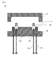
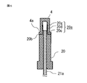
- FIG. 2 is a cross-sectional view showing a state in which an insert product is set in the insert molding die according to Embodiment 1;
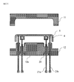
- FIG. 2 is a cross-sectional view showing a closed state of the insert molding die according to Embodiment 1;
- FIG. 2 is a cross-sectional view showing a state where a molded product is protruded from the insert molding die according to Embodiment 1;
- 4 is a flow chart showing a manufacturing process of an insert-molded product using the insert-molding mold according to Embodiment 1.
- FIG. 1 is a perspective view showing the top surface of an insert-molded product according to Embodiment 1.
- FIG. 2 is a perspective view showing the bottom surface of the insert-molded product according to Embodiment 1.
- FIG. 2
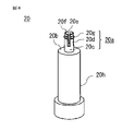
- FIG. 2 is a perspective view showing a core pin of the insert molding die according to Embodiment 1.
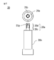
- FIG. 3A and 3B are a plan view and a side view showing a core pin of the insert molding die according to Embodiment 1;
- FIG. 4 is a cross-sectional view showing a state in which an insert is set on the core pin of the insert molding die according to Embodiment 1;
- FIG. 11 is a perspective view showing a core pin of an insert molding die according to Embodiment 2;
- FIG. 11 is a cross-sectional view showing a core pin, an insert-molded product, and an ejector pin after molding of an insert-molding mold according to Embodiment 4;
- FIG. 11 is a cross-sectional view showing a core pin of an insert molding die according to Embodiment 5;
- FIG. 11 is a cross-sectional view showing a state in which an insert is set on a core pin of an insert molding die according to Embodiment 6;
- Embodiment 1 of the present application will be described below.
- insert-molded products to be manufactured in the present application include housings, terminal blocks, and the like for arranging various parts such as electronic parts and sensor parts at predetermined locations by fixing them with bolts.
- the object to be fixed is not particularly limited, and can be arranged in various machines, devices, structures, etc. Examples include an electric steering of automobiles, a power control unit, an engine control unit, and the like.
- such an insert-molded product 1 integrally includes a housing body 2 and a plurality of bolt fixing portions 3 provided on the inner surface of the housing body 2 .
- the shape of the insert-molded product 1 shown in FIG. 1 is illustrated as a simple shape as an example. In practice, the insert-molded product 1 is manufactured in a wide variety of shapes depending on the various components to be accommodated, the place of installation, and the like.
- the mating parts to be fixed by the insert-molded product 1 include a substrate and a plate serving as a lid of the housing body 2 .
- An insert product that constitutes the bolt fixing portion 3 of the insert molded product 1 is a bag-like nut 4 having a female screw.
- the outer shape of the insert may be circular or polygonal such as triangular or quadrangular, and there are no particular restrictions on the shape.
- a flange portion 4a having a flange shape is provided on the outer edge of the bottom surface of the nut 4 in order to secure a contact area between the mating part and the fixing bolt at the opening of the insert part.
- the shape of the flange portion 4a is not limited to a circular shape, and may be a polygonal shape such as a quadrangle, and the shape is not particularly limited.
- this insert molding die 10 includes a fixed side die 11 and a movable side die 12 that can move back and forth relative to the fixed side die 11.
- FIGS. 2A shows a mold open state showing an insert product set
- FIG. 2B shows a mold closed state in which a nut 4 as an insert product is set in the insert molding die 10 .
- a cavity 13 corresponding to the desired shape of the insert-molded product 1 is formed. Molten resin injected through a nozzle from a molding machine is supplied into the cavity 13 through a sprue, a runner and a gate to mold the insert molded product 1 .
- a core pin 20 corresponding to the inner diameter female thread portion of the nut 4 of the insert product is provided in the movable mold 12, and the nut 4 is set on the core pin 20 and is insert-molded.
- the core pin 20 ensures and facilitates the positioning of the nut 4, and prevents the nut 4 from being displaced during injection molding, thereby enabling stable molding.
- the insert molding die 10 is for molding a predetermined shape by injecting resin after setting the nut 4 as an insert product on the core pin 20, and is installed so that the axis is in the vertical direction. 2 and 3, this insert molding die 10 comprises a movable side die 12 movable in the axial direction and a fixed side die 11 provided facing the movable side die 12.
- FIG. 2C shows a state in which the molded product is protruded from the insert molding die 10. As shown in FIG. The insert-molded product 1 is ejected by the ejection pins 21a and 21b, and the insert-molded product 1 can be removed from the insert-molding mold 10 manually or by an automatic machine.
- FIG. 3 shows a flow chart showing the manufacturing process of the insert-molded product 1 .
- step S1 is an insert product setting process.
- step S2 a mold closing process interlocked with the operation of the molding machine is performed, in step S3 an injection process in which molten resin is injected into the closed mold, and in step S4 until the resin solidifies as an insert-molded product.
- step S6 The cooling process of the insert-molded product 1 to be cooled, the mold opening process linked with the operation of the molding machine in step S5, and the ejection process of ejecting the finished insert-molded product 1 in step S6 are carried out in this order. . After the insert-molded product 1 is taken out in step S6, the manufacturing process is repeated by returning to the step of setting the insert product in step S1.
- the movable side mold 12 has a core pin 20 into which the nut 4 is inserted, and a movable side base member 12a in which the core pin 20 is incorporated.
- FIG. 4 is a perspective view of the core pin 20 arranged in the movable mold 12.
- the core pin 20 has a cylindrical holding portion 20a having an outer diameter corresponding to the inner diameter female threaded portion of the nut 4 .
- the holding portion 20a has a tubular portion 20c protruding from an abutment portion 20b where the core pin 20 and the bottom surface of the nut 4 come into contact with each other. ing.
- the tip portion 20d is provided with four slits 20e extending from the tip in the axial direction.
- a taper 20f is provided in the inner surface of each holding portion 20a, that is, the hollow portion and the slit 20e, and has a tapered shape that widens in the outer diameter direction toward the tip of the holding portion 20a. It is assumed that the nominal thread diameter of the nut 4 ranges from M4 to M6, and the configurable range is from M3 to M8. The diameters of the holding portion 20a and the cylindrical portion 20c are large enough to securely hold the nut 4 corresponding to M3 to M8.
- a protruding part 20g having a rounded convex shape is provided on the outer periphery near the tip, protruding to the outer peripheral surface of the cylindrical part 20c.
- the position of the nut 4 is held in contact with the side.
- the trunk portion 20 h of the core pin 20 is arranged inside the movable side base member 12 a of the movable side mold 12 .
- the trunk portion 20h has an axially extending hollow portion that is coaxial with the holding portion 20a.
- a projecting pin 21a is slidably set in the hollow portion.
- FIG. 5A and 5B are a plan view and a side view of the core pin 20 arranged in the movable mold 12.
- FIG. FIG. 6 is a cross-sectional view showing a state in which a nut 4 as an insert product is set on a core pin 20 arranged in the movable mold 12, and a state in which the nut 4 as an insert product is inserted into the holding portion 20a. indicates
- the nut 4 as an insert product is inserted into the holding portion 20a of the core pin 20.
- the outer diameter of the cylindrical portion 20c of the holding portion 20a corresponds to the inner diameter of the nut 4.
- the tip portion 20d of the holding portion 20a has a convex portion 20g, and the diameter of the outer circumference of each of the four rounded convex portions 20g is larger than the diameter of the inner diameter female screw portion of the nut 4.
- the tip portion 20d of the holding portion 20a has a slit 20e, and since the tip portion 20d has elasticity, the nut 4 is pushed in while deforming the tip portion 20d of the holding portion 20a inward. It is set in the holding portion 20a.
- the insert molding die 10 When the nut 4 is held, the insert molding die 10 is closed. In this state, the molten resin is supplied into the cavity 13 through the sprue, runner and gate, and the insert-molded product 1 is molded.
- the nut 4 which is an insert part is evenly pressed by the elastic force of the tip part 20d of the holding part 20a and is securely held, the axis of the nut 4 and the axis of the resin part of the part after insert molding are aligned. Molded to match. In addition, molding can be performed without lifting the nut 4 . That is, it is possible to obtain the insert-molded product 1 in which the resin does not enter the inner diameter female screw portion of the bolt fixing portion 3 .
- the elastic force of the holding portion 20a can be used to smoothly release the insert-molded product 1. Since there are no flaws or damages, and no excessive interfering force is applied, an insert-molded product 1 without deformation can be obtained.
- the holding portion 20a of the core pin 20 is provided with the cylindrical portion 20c and the distal end portion 20d having the slit 20e in the axial direction.
- a certain nut 4 can be held easily and without scratches and damage.
- the slits 20e are provided at equal intervals in the circumferential direction, the inner peripheral surface of the nut 4 is pressed radially outward from the holding portion 20a over the entire length in the axial direction, and is pressed in any direction perpendicular to the axial direction.
- the cross section is also pressed with a uniform force in the radial direction.
- the roundness and coaxiality between the inner peripheral surface of the nut 4 as an insert and the holding portion 20a can be improved.
- the nut 4, which is an insert product is securely held by the holding portion 20a of the core pin 20, and the nut 4 is molded so that the axis of the nut 4 coincides with the axis of the resin portion of the component after insert molding.
- the degree of coaxiality between the axis and the axis of the resin portion of the insert-molded product 1 after insert molding can be improved.
- the insert molding die 10 is vertically installed corresponding to a vertical molding machine. It is not limited to the vertical installation, and the insert molding die 10 is suitable for a horizontal molding machine. It may be placed horizontally. Also in this case, the same effects as in the first embodiment can be obtained.
- the outer diameter of the holding portion 20a of the core pin 20 is assumed to be the same cylindrical shape as the inner diameter of the nut 4, which is an insert product, but the shape is not limited to a cylindrical shape.
- the shape of the inner and outer peripheral surfaces of the holding portion 20a of the core pin 20 may be a cylindrical prismatic shape.
- the shape of the holding portion 20a may be any other shape such as a triangle or a square as long as the elasticity of the tip portion 20d can hold the inner diameter female screw portion of the nut 4, which is an insert product.
- the slits 20e may be provided at irregular intervals according to the shape of the inner peripheral surface. Also in this case, the same effect as in the first embodiment can be obtained.
- Embodiment 3 the slits 20e are provided at four locations, but the number of slits 20e is not limited to four and may be any other number.
- the elastic force of the tip portion 20d of the holding portion 20a acts on the nut 4, which is an insert product, more uniformly over the entire circumference.
- the circularity and coaxiality of the can be further improved. Also in this case, the same effect as in the first embodiment can be obtained.
- FIG. 8 is a sectional view showing the core pin 20 and the projecting pins 21a and 21b of the product arranged in the insert molding die 10 and the insert-molded product 1 after molding.
- a protruding pin 21a is arranged in the central portion of the core pin 20.
- Ejection pins 21b for ejecting the housing body 2 of the insert-molded product 1 after molding are provided scattered at a plurality of locations of the movable-side base member 12a of the movable-side mold 12 .
- the movable side base member 12a is omitted.
- a test shot may be performed by pouring resin into the mold without attaching the insert nut 4 until the operation of the mold is confirmed or until the amount of resin stabilizes.
- the resin flowing into the mold may enter the inside of the holding portion 20a of the core pin 20.
- the inside of the holding portion 20a which is hollow, is clogged with resin, and the elasticity of the tip portion 20d is lost, making it impossible to set the nut 4, which is an insert product.
- a hollow portion is provided in the trunk portion 20h of the core pin 20, and the ejector pin 21a is arranged therein.
- the inner surface of the holding portion 20a is provided with a taper 20f that widens in the outer diameter direction toward the tip.
- FIG. 9 shows a cross-sectional view of a core pin 20 according to Embodiment 5.
- the core pin 20 is divided into a replacement portion 201 and a core pin body portion 202 .
- the replacement portion 201 includes a holding portion 20a and a contact portion 20b for the nut 4, which is an insert product, and is detachably provided on the core pin body portion 202.
- FIG. By adopting such a divided structure, it is possible to prepare the replacement part 201 that matches the shape of the core pin such as the diameter or length of the internal thread of the nut 4 as an insert.
- the replacement part 201 and the core pin main body part 202 may be fixed by providing a screw in the mutual fitting part, or by any other method as long as they can be fixed detachably. By doing so, it is possible to obtain the insert molding die 10 that can cope with changes in the insert product. In addition, when the holding portion 20a is worn or damaged, work can be continued by replacing only the replacement portion 201 without replacing the entire core pin 20, thereby improving maintainability.
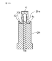
- FIG. 10 is a cross-sectional view showing a state in which an insert is set on a core pin 20 according to Embodiment 6.
- FIG. 10 an outer peripheral wall 20i that is stepped in the axial direction along the outer periphery of the flange portion 4a of the nut 4 is provided on the contact surface between the bottom surface of the nut 4, which is an insert product, and the contact portion 20b of the core pin 20. is provided.
- An outer peripheral wall 20i is provided in which the length of the stepped portion in the axial direction is greater than the length corresponding to the thickness of the flange portion 4a of the nut 4.
- the injected resin flows in the direction in which the nut 4 is pressed against the contact portion 20b. can be pressed down.
- the nut 4 which is an insert product
- the nut 4 can be pressed against the contact portion 20b, and the effect of suppressing the floating of the nut 4 and the intrusion of the molten resin into the nut 4 is improved.
- the female screw opening of the nut 4 that is, the bolt fixing portion 3 of the insert-molded product 1 is perfectly exposed. It is possible to obtain an insert-molded product 1 in which the nut 4, which is an insert product, is not exposed except for the bolt fixing portion 3.
- Insert molded product 1 Insert molded product, 2 Housing body, 3 Bolt fixing part, 4 Nut, 4a Flange part, 10 Insert molding mold, 11 Fixed side mold, 12 Movable side mold, 12a Movable side base member, 13 Cavity, 20 core pin, 20a holding portion, 20b abutting portion, 20c cylindrical portion, 20d tip portion, 20e slit, 20f taper, 20g convex portion, 20h body portion, 20i outer peripheral wall, 21a, 21b projecting pin, 201 replacement portion, 202 core pin body.
Landscapes
- Engineering & Computer Science (AREA)
- Mechanical Engineering (AREA)
- Manufacturing & Machinery (AREA)
- Moulds For Moulding Plastics Or The Like (AREA)
- Injection Moulding Of Plastics Or The Like (AREA)
Abstract
ナット(4)をインサート成形するインサート成形用金型(10)であって、において、前記ナットの底面が当接される当接部(20b)を有する胴部(20h)と、前記胴部から前記ナットの軸方向に突設され、前記ナットのネジ穴に挿入される筒状の保持部(20a)と、を有するコアピン(20)を備え、前記保持部は、前記当接部から突設して前記ナットのネジ穴に内接する筒状部(20c)と、前記筒状部から先端に軸方向のスリット(20e)を有し、前記筒状部の外周面に突出して設けられた凸部(20h)と、を有する。インサート成形品(1)と前記コアピンが前記凸部を有する前記保持部によって嵌合されているため、インサート品であるナットの中心軸とコアピン中心軸が一致する位置に正確にかつ傷なく固定することができる。
Description
本願は、インサート成形用金型およびインサート成形品の製造方法に関するものである。
ナットを埋設した樹脂成形品を射出成形にて製造するためには、インサート品となるナットを所定位置に保持する必要がある。例えば、従来のインサート成形用金型では、特許文献1に示すように、インサート品を支持する金型用コアピンにネジ部を設け、かつピン軸方向にスリットを設けてネジ先に弾性を持たせ、金型へのインサート品埋設とその位置決めを行っていた。
特許文献1のような金型構造にあっては、インサート品となるナットがスリットを設けたコアピンのネジ部と干渉しながら挿入されるため、インサート品の雌ネジ部に傷が生じるという問題があった。成形後のインサート成形品の離型時においても干渉しながら製品が突き出されるため、雌ネジ部に傷及び製品変形が生じるという問題があった。
本願は、傷無くインサート品を配置できるインサート成形用金型と、傷及び変形のないインサート成形品を得ることを目的としている。
本願は、傷無くインサート品を配置できるインサート成形用金型と、傷及び変形のないインサート成形品を得ることを目的としている。
本願に係わるインサート成形用金型は、ナットをインサート成形するインサート成形用金型であって、前記ナットの底面が当接される当接部を有する胴部と、前記胴部から前記ナットの軸方向に突設され、前記ナットのネジ穴に挿入される筒状の保持部と、を有するコアピンを備え、前記保持部は、前記当接部から突設して前記ナットのネジ穴に内接する筒状部と、前記筒状部から先端に軸方向のスリットを有し、前記筒状部の外周面に突出して設けられた凸部と、を有するものである。
本願によれば、インサート品となるナットのねじ側に挿入される保持部の先端にスリットを有するため、先端部は弾性を持ち、かつ先端付近の外周に凸部が設けられているため、インサート品であるナットの中心軸とコアピン中心軸が一致する位置に正確にかつ傷なく固定することができる。
実施の形態1.
以下、本願の実施の形態1について説明する。本願の製造対象であるインサート成形品としては、例えば電子部品、センサ部品などの各種部品を、所定箇所にボルト固定により配設するための筐体、端子台などが挙げられる。固定対象は特に限定されず、種々の機械、装置、構造物等に配設することができるが、例としては自動車等の電動ステアリング、パワーコントロールユニット、エンジンコントロールユニット等が挙げられる。
以下、本願の実施の形態1について説明する。本願の製造対象であるインサート成形品としては、例えば電子部品、センサ部品などの各種部品を、所定箇所にボルト固定により配設するための筐体、端子台などが挙げられる。固定対象は特に限定されず、種々の機械、装置、構造物等に配設することができるが、例としては自動車等の電動ステアリング、パワーコントロールユニット、エンジンコントロールユニット等が挙げられる。
このようなインサート成形品1は、図1Aおよび図1Bに示すように、筐体本体2と、筐体本体2の内面に設けられた複数のボルト固定部3とを一体的に備える。なお、図1に示すインサート成形品1の形状は一例として簡単な形状を図示している。実際には、収容する各種部品、設置場所等に応じてインサート成形品1は多種多様な形状に製造される。また、インサート成形品1によって固定される対象の相手部品としては、基板および筐体本体2の蓋となるプレートなどがある。
上記インサート成形品1を製造するためのインサート成形用金型10の構成について、図2Aから図2Cを用いて説明する。インサート成形品1のボルト固定部3を構成するインサート品は、雌ネジを有する袋状のナット4である。インサート品の外形は円形のほか、三角形または四角形等の多角形でもよく、特に形状の制限はない。また、インサート品の開口部に相手部品と固定用ボルトとの接触面積確保のため、ナット4の底面の外縁にフランジ形状を持ったフランジ部4aを有する。このフランジ部4aの形状も円形に限らず四角形等の多角形でもよく、特に形状の制限はない。
このインサート成形用金型10は、図2Aから図2Cに示すように、固定側金型11と、固定側金型11に対して相対的に進退可能な可動側金型12とを備える。図2Aはインサート品セットを示す型開き状態であり、図2Bはインサート品となるナット4をインサート成形用金型10にセットされた状態の型閉じ状態である。可動側金型12を固定側金型11に突き合わせた型閉じ状態では、求めるインサート成形品1の形状に応じた空洞であるキャビティ13が形成される。このキャビティ13内には、成形機からのノズルを介して射出される溶融樹脂がスプルー、ランナー及びゲートを通して供給されインサート成形品1が成形される。
可動側金型12には、インサート品のナット4の内径雌ネジ部に対応したコアピン20が配設されており、ナット4はこのコアピン20にセットされインサート成形される。このコアピン20により、ナット4の位置決めが確実かつ容易になると共に、射出成形時にナット4の位置ズレが防がれて安定成形が可能となる。
インサート成形用金型10は、コアピン20にインサート品となるナット4をセットした後に樹脂を注入して所定の形状を成形するものであり、軸線が鉛直方向になるように設置されている。図2および図3において、このインサート成形用金型10は、軸線方向に移動可能な可動側金型12と、可動側金型12に対向して設けられた固定側金型11とを備えている。可動側金型12の軸線と固定側金型11の軸線とは、一致するように調節されている。また、可動側金型12には成形後のインサート成形品1を取り出すための突き出しピン21a、21bが設けられている。図2Cにインサート成形用金型10の成形品突き出し状態を示す。突き出しピン21aおよび21bによってインサート成形品1が突き出され、インサート成形品1はインサート成形用金型10から手動もしくは自動機で取り出すことができる。
インサート成形用金型10は、コアピン20にインサート品となるナット4をセットした後に樹脂を注入して所定の形状を成形するものであり、軸線が鉛直方向になるように設置されている。図2および図3において、このインサート成形用金型10は、軸線方向に移動可能な可動側金型12と、可動側金型12に対向して設けられた固定側金型11とを備えている。可動側金型12の軸線と固定側金型11の軸線とは、一致するように調節されている。また、可動側金型12には成形後のインサート成形品1を取り出すための突き出しピン21a、21bが設けられている。図2Cにインサート成形用金型10の成形品突き出し状態を示す。突き出しピン21aおよび21bによってインサート成形品1が突き出され、インサート成形品1はインサート成形用金型10から手動もしくは自動機で取り出すことができる。
また、図3にインサート成形品1の製造工程を示すフローチャートを示す。図3に示されるように、コアピン20が配設されたインサート成形用金型10によるインサート成形品1の製造工程は、インサート品となるナット4をインサート成形用金型10のコアピン20にセットするインサート品セット工程となるステップS1から始まる。以下、ステップS2で成形機の動作と連動した型閉じ工程が行われ、ステップS3で閉じられた型の中に溶融樹脂が注入される射出工程、ステップS4で樹脂がインサート成形品として固化するまで冷却するインサート成形品1の冷却工程、ステップS5で成形機の動作と連動した型開き工程、ステップS6で出来上がった完成品となるインサート成形品1を突き出す突き出し工程の順で各工程が実施される。ステップS6でインサート成形品1が取り出された後、再度ステップS1のインサート品セットの工程に戻って製造作業工程が繰り返される。
可動側金型12は、ナット4が挿入されるコアピン20と、コアピン20が組み込まれた可動側ベース部材12aとを有している。図4は、可動側金型12に配設されているコアピン20の斜視図である。コアピン20には、ナット4の内径雌ネジ部に対応した外径を持つ筒状の保持部20aを有する。保持部20aには、コアピン20とナット4の底面とが当接する当接部20bから突設する筒状部20cがあり、筒状部20cから軸方向に枝分かれする形で先端部20dが形成されている。先端部20dには、先端から軸線方向に伸びる4箇所のスリット20eから設けられている。また、それぞれの保持部20aの内面すなわち中空部とスリット20eには保持部20aの先端に向けて外径方向に広がるテーパ形状となるテーパ20fが設けられている。
なお、ナット4のネジ呼び径はM4からM6を想定しており、構成可能範囲はM3からM8である。保持部20aおよび筒状部20cの径はM3からM8に相当するナット4が確実に保持できる大きさとなる。
なお、ナット4のネジ呼び径はM4からM6を想定しており、構成可能範囲はM3からM8である。保持部20aおよび筒状部20cの径はM3からM8に相当するナット4が確実に保持できる大きさとなる。
保持部20aの先端部20dには、先端付近の外周に筒状部20cの外周面に突出して、外径側に丸みを帯びた凸形状の凸部20gが設けられており、ナット4の内径側に接してナット4の位置を保持する。
また、コアピン20の胴部20hは、可動側金型12の可動側ベース部材12aの内部に配置される。胴部20hには、保持部20aと同軸となる軸方向の伸びた中空部を持つ。その中空部の中に突き出しピン21aがスライド自在にセットされている。
また、コアピン20の胴部20hは、可動側金型12の可動側ベース部材12aの内部に配置される。胴部20hには、保持部20aと同軸となる軸方向の伸びた中空部を持つ。その中空部の中に突き出しピン21aがスライド自在にセットされている。
以下、上記構成のインサート成形用金型10の作用について、図5および図6を用いて説明する。図5は可動側金型12に配設されているコアピン20の平面図および側面図である。図6は可動側金型12に配設されているコアピン20にインサート品であるナット4がセットされた状態の断面図であり、インサート品となるナット4が、保持部20aに挿入された状態を示す。
まず、インサート成形用金型10が型開き状態にあるときに、インサート品となるナット4がコアピン20の保持部20aに挿入される。ここで、保持部20aの筒状部20cの外径はナット4の内径に対応している。保持部20aの先端部20dが凸部20gを有しており、この丸みを帯びた4箇所それぞれの凸部20gの外周円の径はナット4の内径雌ネジ部の径より大きい。また、保持部20aの先端部20dはスリット20eを有しており、先端部20dは弾性を持つため、ナット4は、保持部20aの先端部20dを内側に変形させながら押し込まれ、傷及び損傷なく保持部20aにセットされる。
ナット4が保持されるとインサート成形用金型10が閉じられる。この状態で溶融樹脂がスプルー、ランナー及びゲートを通してキャビティ13内に供給されインサート成形品1が成形される。ここで、インサート品となるナット4が保持部20aの先端部20dの弾性力によって均等に押圧され確実に保持されているので、ナット4の軸線とインサート成形後の部品の樹脂部分の軸線とが一致するように成形される。また、ナット4の浮き上がりもなく成形することができる。すなわちボルト固定部3の内径雌ネジ部への樹脂の侵入の無いインサート成形品1を得ることができる。
また、成形後の製品突き出し時も同様に、ナット4がコアピン20にネジ嵌合されていないため、保持部20aの弾性力を利用し、インサート成形品1をスムーズに離型することができ、傷及び損傷がなく、さらには無理な干渉力がかかることが無いため、変形のないインサート成形品1を得ることができる。
また、成形後の製品突き出し時も同様に、ナット4がコアピン20にネジ嵌合されていないため、保持部20aの弾性力を利用し、インサート成形品1をスムーズに離型することができ、傷及び損傷がなく、さらには無理な干渉力がかかることが無いため、変形のないインサート成形品1を得ることができる。
実施の形態1に係わるインサート成形用金型10によれば、コアピン20の保持部20aに筒状部20cと、さらに軸線方向のスリット20eを有する先端部20dとを設けたことにより、インサート品であるナット4を容易に、かつ傷及び損傷なく保持することができる。また、スリット20eが周方向に等間隔に設けられているので、ナット4の内周面は、軸線方向の全長にわたって保持部20aから径方向外側に押圧されるとともに、軸線方向に垂直であるどの断面についても径方向に均一な力で押圧される。これによりインサート品となるナット4の内周面と保持部20aとの真円度、同軸度を向上させることができる。
また、インサート品であるナット4がコアピン20の保持部20aによって確実に保持され、ナット4の軸線とインサート成形後の部品の樹脂部分の軸線とが一致するように成形されるので、ナット4の軸線とインサート成形後のインサート成形品1の樹脂部分の軸線との同軸度を向上させることができる。
また、インサート品であるナット4がコアピン20の保持部20aによって確実に保持され、ナット4の軸線とインサート成形後の部品の樹脂部分の軸線とが一致するように成形されるので、ナット4の軸線とインサート成形後のインサート成形品1の樹脂部分の軸線との同軸度を向上させることができる。
また、インサート成形用金型10は縦型成形機に対応した縦置きである場合について説明したが、縦置きに限定されるものではなく、インサート成形用金型10は横型成形機に対応して横置きにされてもよい。この場合も、上記の実施の形態1と同様の効果を得ることができる。
実施の形態2.
上記実施の形態1では、コアピン20の保持部20aの外径はインサート品であるナット4の内径と同じ円筒形状であるものとして説明したが、円筒形状に限定されるものではない。図7に示すようにコアピン20の保持部20aの内周及び外周面の形状は、筒状の角柱となる形状であってもよい。先端部20dの弾性により、インサート品となるナット4の内径雌ネジ部を保持することができるものであれば、保持部20aの形状は三角形または四角形等他の形状であってもよい。また、スリット20eが内周面の形状に合わせて不等間隔に設けられてもよい。その場合も、上記実施の形態1と同様の効果を得ることができる。
上記実施の形態1では、コアピン20の保持部20aの外径はインサート品であるナット4の内径と同じ円筒形状であるものとして説明したが、円筒形状に限定されるものではない。図7に示すようにコアピン20の保持部20aの内周及び外周面の形状は、筒状の角柱となる形状であってもよい。先端部20dの弾性により、インサート品となるナット4の内径雌ネジ部を保持することができるものであれば、保持部20aの形状は三角形または四角形等他の形状であってもよい。また、スリット20eが内周面の形状に合わせて不等間隔に設けられてもよい。その場合も、上記実施の形態1と同様の効果を得ることができる。
実施の形態3.
実施の形態1および実施の形態2では、スリット20eは4箇所に設けられているとしたが、スリット20eの数は4箇所に限定されるものではなく、その他の数であってもよい。スリット20eの数を増やした場合は、保持部20aの先端部20dの弾性力が全周にわたってより均一にインサート品であるナット4に働くので、インサート成形品1に対するナット4の位置精度および外周面の真円度および同軸度をさらに向上させることができる。また、その場合も、実施の形態1と同様の効果を得ることができる。
実施の形態1および実施の形態2では、スリット20eは4箇所に設けられているとしたが、スリット20eの数は4箇所に限定されるものではなく、その他の数であってもよい。スリット20eの数を増やした場合は、保持部20aの先端部20dの弾性力が全周にわたってより均一にインサート品であるナット4に働くので、インサート成形品1に対するナット4の位置精度および外周面の真円度および同軸度をさらに向上させることができる。また、その場合も、実施の形態1と同様の効果を得ることができる。
実施の形態4.
図8はインサート成形用金型10に配設されるコアピン20および製品の突き出しピン21a、21bと成形後のインサート成形品1を示す断面図である。図8に示すようにコアピン20の中央部に突き出しピン21aが配置されている。また、成形後のインサート成形品1の筐体本体2を押し出すための突き出しピン21bが可動側金型12の可動側ベース部材12aの複数個所に点在して設けられている。ただし、図8では可動側ベース部材12aを省略して描いている。
図8はインサート成形用金型10に配設されるコアピン20および製品の突き出しピン21a、21bと成形後のインサート成形品1を示す断面図である。図8に示すようにコアピン20の中央部に突き出しピン21aが配置されている。また、成形後のインサート成形品1の筐体本体2を押し出すための突き出しピン21bが可動側金型12の可動側ベース部材12aの複数個所に点在して設けられている。ただし、図8では可動側ベース部材12aを省略して描いている。
成形品の製造を始める前の準備として、金型の動作確認時または樹脂量安定までの間、インサート品であるナット4の装着無しで金型に樹脂を流す試し打ちを行うことがある。試し打ち時には、金型に流れる樹脂はコアピン20の保持部20aの内部にまで侵入することがある。その場合、中空状となっている保持部20aの内側に樹脂が詰まり先端部20dの弾性がなくなりインサート品であるナット4がセットできなくなる。
このような問題を解決するために、コアピン20の胴部20hには中空部を設け、その中に突き出しピン21aを配置している。また、保持部20aの内面には、先端に向けて外径方向に広がるテーパ20fが設けられている。このような構造を設けたことで、製品突き出し工程で突き出しピン21aを保持部20a側に突き出し、試し打ち時の保持部20aの樹脂詰まりを容易に取り除くことができる。
このような問題を解決するために、コアピン20の胴部20hには中空部を設け、その中に突き出しピン21aを配置している。また、保持部20aの内面には、先端に向けて外径方向に広がるテーパ20fが設けられている。このような構造を設けたことで、製品突き出し工程で突き出しピン21aを保持部20a側に突き出し、試し打ち時の保持部20aの樹脂詰まりを容易に取り除くことができる。
実施の形態5.
図9は実施の形態5に係わるコアピン20の断面図を示すものである。図9に示すようにコアピン20を交換部201とコアピン本体部202の2つに分割したものである。交換部201は、保持部20aとインサート品であるナット4との当接部20bとを含み、コアピン本体部202に着脱自在に設けられる。このような分割構造とすることでインサート品となるナット4の雌ネジの径または長さなどコアピン形状に合わせた交換部201を用意することができる。交換部201とコアピン本体部202との固定は、互いの嵌合部にネジを設けてもよいし、着脱自在に固定できる方法であれば他の方法でも構わない。
このようにすることで、インサート品の変更に対応することが可能なインサート成形用金型10を得ることができる。また、保持部20aの摩耗時および破損時の交換もコアピン20の全てを交換せずとも交換部201の交換のみで作業を継続することができ、保守性の向上が図れる。
図9は実施の形態5に係わるコアピン20の断面図を示すものである。図9に示すようにコアピン20を交換部201とコアピン本体部202の2つに分割したものである。交換部201は、保持部20aとインサート品であるナット4との当接部20bとを含み、コアピン本体部202に着脱自在に設けられる。このような分割構造とすることでインサート品となるナット4の雌ネジの径または長さなどコアピン形状に合わせた交換部201を用意することができる。交換部201とコアピン本体部202との固定は、互いの嵌合部にネジを設けてもよいし、着脱自在に固定できる方法であれば他の方法でも構わない。
このようにすることで、インサート品の変更に対応することが可能なインサート成形用金型10を得ることができる。また、保持部20aの摩耗時および破損時の交換もコアピン20の全てを交換せずとも交換部201の交換のみで作業を継続することができ、保守性の向上が図れる。
実施の形態6.
図10は実施の形態6に係わるコアピン20にインサート品がセットされた状態を示す断面図である。図10に示すように、インサート品であるナット4の底面とコアピン20の当接部20bとの当接面に、ナット4のフランジ部4aの外周に沿って軸方向に段となる外周壁20iが設けられている。ナット4のフランジ部4aの厚みとなる長さより軸方向の段部の長さが大きい外周壁20iを設ける。そうすることで、インサート成形品1のボルト固定部3の形状に関わらず、射出される樹脂がナット4を当接部20bに押さえつける方向に樹脂が流れるため、ナット4を当接部20bに確実に押さえつけることができる。このように構成することで、金型内に射出注入された溶融樹脂のナット4内への侵入を堰き止めるという効果を得ることができる。
このようにして、インサート品であるナット4を当接部20bに押さえつけることができ、ナット4の浮き上がりおよびナット4内への溶融樹脂の侵入を抑制する効果が向上する。また、これにより得られるインサート成形品1は、ナット4の雌ネジ開口部、すなわちインサート成形品1のボルト固定部3の露出が完璧に行われる。ボルト固定部3以外にインサート品であるナット4の露出がないインサート成形品1を得ることができる。
図10は実施の形態6に係わるコアピン20にインサート品がセットされた状態を示す断面図である。図10に示すように、インサート品であるナット4の底面とコアピン20の当接部20bとの当接面に、ナット4のフランジ部4aの外周に沿って軸方向に段となる外周壁20iが設けられている。ナット4のフランジ部4aの厚みとなる長さより軸方向の段部の長さが大きい外周壁20iを設ける。そうすることで、インサート成形品1のボルト固定部3の形状に関わらず、射出される樹脂がナット4を当接部20bに押さえつける方向に樹脂が流れるため、ナット4を当接部20bに確実に押さえつけることができる。このように構成することで、金型内に射出注入された溶融樹脂のナット4内への侵入を堰き止めるという効果を得ることができる。
このようにして、インサート品であるナット4を当接部20bに押さえつけることができ、ナット4の浮き上がりおよびナット4内への溶融樹脂の侵入を抑制する効果が向上する。また、これにより得られるインサート成形品1は、ナット4の雌ネジ開口部、すなわちインサート成形品1のボルト固定部3の露出が完璧に行われる。ボルト固定部3以外にインサート品であるナット4の露出がないインサート成形品1を得ることができる。
なお、本願の実施の形態では、インサート品として袋状のナット4を埋め込んだインサート成形品1の例で記述したが、袋状ナットの形態でなくてもコアピン20の保持部20aに装着したナット4の穴の反対側に蓋を設けるなど、保持部20a内部への樹脂の侵入を防ぐため構造を設けたものであれば、同じ効果を得ることが可能である。
本願は、様々な例示的な実施の形態および実施例が記載されているが、1つ、または複数の実施の形態に記載された様々な特徴、態様、および機能は特定の実施の形態の適用に限られるのではなく、単独で、または様々な組み合わせで実施の形態に適用可能である。従って、例示されていない無数の変形例が、本願明細書に開示される技術の範囲内において想定される。例えば、少なくとも1つの構成要素を変形する場合、追加する場合または省略する場合、さらには、少なくとも1つの構成要素を抽出し、他の実施の形態の構成要素と組み合わせる場合が含まれるものとする。
1 インサート成形品、2 筐体本体、3 ボルト固定部、4 ナット、4a フランジ部、10 インサート成形用金型、11 固定側金型、12 可動側金型、12a 可動側ベース部材、13 キャビティ、20 コアピン、20a 保持部、20b 当接部、20c 筒状部、20d 先端部、20e スリット、20f テーパ、20g 凸部、20h 胴部、20i 外周壁、21a,21b 突き出しピン、201 交換部、202 コアピン本体部。
Claims (7)
- ナットをインサート成形するインサート成形用金型であって、
前記ナットの底面が当接される当接部を有する胴部と、
前記胴部から前記ナットの軸方向に突設され、前記ナットのネジ穴に挿入される筒状の保持部と、
を有するコアピンを備え、
前記保持部は、前記当接部から突設して前記ナットのネジ穴に内接する筒状部と、
前記筒状部の先端に軸方向のスリットを有し、前記筒状部の外周面に突出して設けられた凸部と、
を有することを特徴とするインサート成形用金型。 - 前記保持部のスリットは4本設けられていることを特徴とする請求項1に記載のインサート成形用金型。
- 前記コアピンの胴部には、前記保持部と同軸となる中空部を有し、
前記中空部に軸方向にスライド自在な突き出しピンが設けられていることを特徴とする請求項1または請求項2に記載のインサート成形用金型。 - 前記保持部の内面は、先端に向けて外径方向に広がるテーパ形状を有していることを特徴とする請求項1から請求項3のいずれか1項に記載のインサート成形用金型。
- 前記コアピンには、前記保持部と前記当接部とを有する交換部がコアピン本体部から着脱自在に設けられていることを特徴とする請求項1から請求項4のいずれか1項に記載のインサート成形用金型。
- 前記ナットは底面に外縁となるフランジ部を有し、
前記ナットの底面と接する前記コアピンの当接部には、前記フランジ部の外周に沿って軸方向に段となる外周壁が設けられ、
前記外周壁の軸方向の長さが前記フランジ部の軸方向の長さより大きいことを特徴とする請求項1から請求項5のいずれか1項に記載のインサート成形用金型。 - 請求項1から請求項6のいずれか1項に記載のインサート成形用金型によるインサート成形品の製造方法であって、
前記ナットを前記コアピンにセットするセット工程と、成型機と連動した型閉じ工程と、閉じられた型の中に溶融樹脂が注入される射出工程と、樹脂がインサート成形品として固化するまで冷却する冷却工程と、成型機と連動した型開き工程と、完成されたインサート成形品を突き出す突き出し工程と、を含むことを特徴とするインサート成形品の製造方法。
Applications Claiming Priority (2)
| Application Number | Priority Date | Filing Date | Title |
|---|---|---|---|
| JP2021104543 | 2021-06-24 | ||
| JP2021-104543 | 2021-06-24 |
Publications (1)
| Publication Number | Publication Date |
|---|---|
| WO2022270146A1 true WO2022270146A1 (ja) | 2022-12-29 |
Family
ID=84545635
Family Applications (1)
| Application Number | Title | Priority Date | Filing Date |
|---|---|---|---|
| PCT/JP2022/018681 Ceased WO2022270146A1 (ja) | 2021-06-24 | 2022-04-25 | インサート成形用金型およびインサート成形品の製造方法 |
Country Status (1)
| Country | Link |
|---|---|
| WO (1) | WO2022270146A1 (ja) |
Citations (4)
| Publication number | Priority date | Publication date | Assignee | Title |
|---|---|---|---|---|
| JPS609614U (ja) * | 1983-06-30 | 1985-01-23 | 三菱電機株式会社 | 注型金型 |
| JPH07276388A (ja) * | 1994-04-06 | 1995-10-24 | Mitsubishi Electric Corp | 注型用金型 |
| JP2004249565A (ja) * | 2003-02-20 | 2004-09-09 | Mitsubishi Electric Corp | インサート成形体、インサート成形用金型、およびインサート成形体の製造方法 |
| JP2007062040A (ja) * | 2005-08-29 | 2007-03-15 | Mitsubishi Electric Corp | インサート成形金型 |
-
2022
- 2022-04-25 WO PCT/JP2022/018681 patent/WO2022270146A1/ja not_active Ceased
Patent Citations (4)
| Publication number | Priority date | Publication date | Assignee | Title |
|---|---|---|---|---|
| JPS609614U (ja) * | 1983-06-30 | 1985-01-23 | 三菱電機株式会社 | 注型金型 |
| JPH07276388A (ja) * | 1994-04-06 | 1995-10-24 | Mitsubishi Electric Corp | 注型用金型 |
| JP2004249565A (ja) * | 2003-02-20 | 2004-09-09 | Mitsubishi Electric Corp | インサート成形体、インサート成形用金型、およびインサート成形体の製造方法 |
| JP2007062040A (ja) * | 2005-08-29 | 2007-03-15 | Mitsubishi Electric Corp | インサート成形金型 |
Similar Documents
| Publication | Publication Date | Title |
|---|---|---|
| US20140070454A1 (en) | Die for insert molding and method for insert molding of collar | |
| RU2552814C2 (ru) | Безопочная литейная форма и способ ее изготовления | |
| JP2001026040A (ja) | 射出成形用金型 | |
| JP4659286B2 (ja) | 円筒成形品の射出成形型および射出成形方法 | |
| CN113853289A (zh) | 带有对中装置的注塑模具 | |
| WO2022270146A1 (ja) | インサート成形用金型およびインサート成形品の製造方法 | |
| JP5058525B2 (ja) | インサート成形品の製造方法及び製造装置 | |
| JPH0310015Y2 (ja) | ||
| KR100909682B1 (ko) | 오일 필터 성형용 금형 | |
| JP5244426B2 (ja) | 表皮材インサート成形装置および成形方法 | |
| JP6867920B2 (ja) | インサート成形用金型及びこれにより得られる樹脂成形品 | |
| CN212736808U (zh) | 一种嵌件注塑快速放置金属组件的模具镶件 | |
| US10611069B2 (en) | Injection-molding method for mesh filter, injection-molding mold, and mesh filter | |
| CN114986793A (zh) | 螺母碰穿埋入注塑工艺及其成型模具 | |
| JP2007301861A (ja) | 射出成形方法 | |
| JP6679470B2 (ja) | 金型装置、インサート成形品の製造方法、及びインサート成形品 | |
| US4772198A (en) | Apparatus for injection-molding threaded plastic caps and stoppers | |
| JPH0320330B2 (ja) | ||
| JPH0711949Y2 (ja) | インサート成形用金型 | |
| CN114102970A (zh) | 嵌件模制装置及模制方法 | |
| JPH09207137A (ja) | インサート金具自動調芯金型 | |
| JP5659251B2 (ja) | 軸受の成形方法 | |
| JP2004358689A (ja) | モータのロータ製造方法、及びその装置 | |
| KR101476969B1 (ko) | 버(burr)를 최소화하는 인서트 사출방법 | |
| JP2677142B2 (ja) | 射出成形用金型のコアピン構造 |
Legal Events
| Date | Code | Title | Description |
|---|---|---|---|
| 121 | Ep: the epo has been informed by wipo that ep was designated in this application |
Ref document number: 22828065 Country of ref document: EP Kind code of ref document: A1 |
|
| NENP | Non-entry into the national phase |
Ref country code: DE |
|
| 122 | Ep: pct application non-entry in european phase |
Ref document number: 22828065 Country of ref document: EP Kind code of ref document: A1 |
|
| NENP | Non-entry into the national phase |
Ref country code: JP |