WO2022270127A1 - シールリングおよびそれを含む密封構造体 - Google Patents
シールリングおよびそれを含む密封構造体 Download PDFInfo
- Publication number
- WO2022270127A1 WO2022270127A1 PCT/JP2022/017399 JP2022017399W WO2022270127A1 WO 2022270127 A1 WO2022270127 A1 WO 2022270127A1 JP 2022017399 W JP2022017399 W JP 2022017399W WO 2022270127 A1 WO2022270127 A1 WO 2022270127A1
- Authority
- WO
- WIPO (PCT)
- Prior art keywords
- shaft
- seal ring
- axis
- face
- cross
- Prior art date
- Legal status (The legal status is an assumption and is not a legal conclusion. Google has not performed a legal analysis and makes no representation as to the accuracy of the status listed.)
- Ceased
Links
Images



Classifications
-
- F—MECHANICAL ENGINEERING; LIGHTING; HEATING; WEAPONS; BLASTING
- F16—ENGINEERING ELEMENTS AND UNITS; GENERAL MEASURES FOR PRODUCING AND MAINTAINING EFFECTIVE FUNCTIONING OF MACHINES OR INSTALLATIONS; THERMAL INSULATION IN GENERAL
- F16J—PISTONS; CYLINDERS; SEALINGS
- F16J15/00—Sealings
- F16J15/16—Sealings between relatively-moving surfaces
- F16J15/18—Sealings between relatively-moving surfaces with stuffing-boxes for elastic or plastic packings
- F16J15/188—Split assemblies
-
- F—MECHANICAL ENGINEERING; LIGHTING; HEATING; WEAPONS; BLASTING
- F16—ENGINEERING ELEMENTS AND UNITS; GENERAL MEASURES FOR PRODUCING AND MAINTAINING EFFECTIVE FUNCTIONING OF MACHINES OR INSTALLATIONS; THERMAL INSULATION IN GENERAL
- F16J—PISTONS; CYLINDERS; SEALINGS
- F16J15/00—Sealings
- F16J15/16—Sealings between relatively-moving surfaces
- F16J15/18—Sealings between relatively-moving surfaces with stuffing-boxes for elastic or plastic packings
-
- F—MECHANICAL ENGINEERING; LIGHTING; HEATING; WEAPONS; BLASTING
- F16—ENGINEERING ELEMENTS AND UNITS; GENERAL MEASURES FOR PRODUCING AND MAINTAINING EFFECTIVE FUNCTIONING OF MACHINES OR INSTALLATIONS; THERMAL INSULATION IN GENERAL
- F16J—PISTONS; CYLINDERS; SEALINGS
- F16J15/00—Sealings
- F16J15/16—Sealings between relatively-moving surfaces
- F16J15/32—Sealings between relatively-moving surfaces with elastic sealings, e.g. O-rings
-
- F—MECHANICAL ENGINEERING; LIGHTING; HEATING; WEAPONS; BLASTING
- F16—ENGINEERING ELEMENTS AND UNITS; GENERAL MEASURES FOR PRODUCING AND MAINTAINING EFFECTIVE FUNCTIONING OF MACHINES OR INSTALLATIONS; THERMAL INSULATION IN GENERAL
- F16J—PISTONS; CYLINDERS; SEALINGS
- F16J15/00—Sealings
- F16J15/16—Sealings between relatively-moving surfaces
- F16J15/164—Sealings between relatively-moving surfaces the sealing action depending on movements; pressure difference, temperature or presence of leaking fluid
-
- F—MECHANICAL ENGINEERING; LIGHTING; HEATING; WEAPONS; BLASTING
- F16—ENGINEERING ELEMENTS AND UNITS; GENERAL MEASURES FOR PRODUCING AND MAINTAINING EFFECTIVE FUNCTIONING OF MACHINES OR INSTALLATIONS; THERMAL INSULATION IN GENERAL
- F16J—PISTONS; CYLINDERS; SEALINGS
- F16J15/00—Sealings
- F16J15/16—Sealings between relatively-moving surfaces
- F16J15/32—Sealings between relatively-moving surfaces with elastic sealings, e.g. O-rings
- F16J15/3268—Mounting of sealing rings
- F16J15/3272—Mounting of sealing rings the rings having a break or opening, e.g. to enable mounting on a shaft otherwise than from a shaft end
-
- F—MECHANICAL ENGINEERING; LIGHTING; HEATING; WEAPONS; BLASTING
- F16—ENGINEERING ELEMENTS AND UNITS; GENERAL MEASURES FOR PRODUCING AND MAINTAINING EFFECTIVE FUNCTIONING OF MACHINES OR INSTALLATIONS; THERMAL INSULATION IN GENERAL
- F16J—PISTONS; CYLINDERS; SEALINGS
- F16J15/00—Sealings
- F16J15/54—Other sealings for rotating shafts
Definitions
- the present invention relates to a seal ring and a sealing structure including the same.
- a reduction gear for a motor mechanism such as an electric vehicle (EV) or a hybrid electric vehicle (HEV) uses a sealing structure to prevent leakage of cooling oil in the reduction gear.
- a seal ring is included in such a sealing structure, and the seal ring is used to seal the gap between the shaft and the shaft hole into which the shaft is inserted.
- the seal ring is housed inside a groove formed in the outer peripheral surface of the shaft, and seals the gap between the shaft and the shaft hole by coming into contact with the inner surface of the member that forms the shaft hole. cooling oil) from coming out of the shaft hole, and maintains the hydraulic pressure of the cooling oil, etc., in the gap between the shaft and the shaft hole.
- the seal ring is usually not endless, but divided, and has a joint portion in the divided portion (see, for example, Patent Document 1).
- the hydraulic pressure of the cooling oil in the speed reducer of the motor mechanism of an electric vehicle (EV) or hybrid electric vehicle (HEV) is small or no pressure. That is, the hydraulic pressure applied to the seal ring is much lower than the pressure (hydraulic pressure) applied to the seal ring used for sealing hydraulic oil in an automatic transmission (AT), a continuously variable transmission (CVT), or the like.
- a seal ring used in a low-pressure environment such as a speed reducer is usually molded by a method such as injection molding using a resin material. Further, for example, when the seal ring is formed by injection molding, the seal ring is formed in a state in which the abutment portion is widened, and then corrected (diameter-reduced) so as to have a desired diameter. However, it is difficult to correct the abutment and its vicinity. In particular, when a hard resin such as PEEK (polyetheretherketone) or PPS (polyphenylene sulfide) is used as the resin material, it is more difficult to straighten to a desired diameter.
- PEEK polyetheretherketone
- PPS polyphenylene sulfide
- the roundness of the seal ring in the state of use is insufficient, and a gap is formed between the inner surface of the member that constitutes the shaft hole and the outer peripheral surface of the seal ring. It is formed.
- AT automatic transmission
- CVT continuously variable transmission
- the seal ring is pressed against the inner surface of the shaft hole due to the application of high pressure hydraulic oil, and the seal ring loses its perfect circle.
- the clearance on the outer peripheral side due to the insufficient degree disappears.
- low or no hydraulic pressure is applied, such as in a reduction gear, it is difficult to press the seal ring against the inner surface of the shaft hole, and a gap may be formed on the outer peripheral side of the seal ring.
- an object of the present invention is to provide a seal ring and a sealing structure including the seal ring that can suppress the occurrence of a gap between the inner surface of the shaft hole and the outer peripheral surface of the seal ring.
- a sealing structure including a shaft, a member having a shaft hole into which the shaft is inserted, and a seal ring for sealing a gap between an outer surface of the shaft and an inner surface of the member forming the shaft hole.
- the shaft has an annular groove centered on the axial center line on the outer surface, and the bottom surface of the groove has at least one concave portion in the circumferential direction, which is recessed in a direction approaching the axial center line.
- the seal ring has the same number of protrusions as the recesses protruding from its inner peripheral surface in a direction toward the axis, and the diameter of the portion of the protrusions closest to the axis is the same as the diameter of the groove on the shaft.
- both the end face X and the end face Y are straight lines in a cross section perpendicular to the axial center line, and the angle ⁇ of the straight line representing the end face X with respect to the radial direction of the seal ring and the straight line axis representing the end face Y with respect to the radial direction are both 45 degrees or more.
- the seal ring has an abutment
- the sealing structure according to (1) above wherein the center X c of the end face X in the circumferential direction is within a range of 20 to 60 degrees with respect to the abutment in a cross section perpendicular to the axial center line.
- a shaft and a member having a shaft hole into which the shaft is inserted the shaft having an annular groove centered on its axis on its outer surface, and a bottom surface of the groove has at least one recess in the circumferential direction that is recessed in a direction approaching the axial center line, and in a cross section perpendicular to the axial center line, the end face Y in the circumferential direction of the recess is a straight line, and the straight line
- a seal ring that can suppress the occurrence of a gap between the inner surface of the shaft hole and the outer peripheral surface of the seal ring, and a sealing structure including the seal ring.
- FIG. 1 is a schematic cross-sectional view in a direction perpendicular to an axis L of a sealing structure of the present invention
- FIG. FIG. 2 is a schematic cross-sectional view in a direction parallel to the axial center line L of the sealing structure of the present invention, and is a cross-sectional view (schematic cross-sectional view) taken along line AA shown in FIG. 1
- FIG. 4 is a schematic diagram showing a side view of a seal ring
- FIG. 4 is a partially enlarged perspective view (schematic diagram) enlarging the vicinity of the convex portion of the seal ring shown in FIG. 3;
- FIG. 4 is a partially enlarged perspective view (schematic diagram) enlarging the vicinity of the abutment portion of the seal ring shown in FIG. 3 ;
- FIG. 3 is a schematic cross-sectional view showing a cross section of a shaft and a shaft hole into which the shaft is inserted, which the sealing structure of the present invention has;
- FIG. 5 is an enlarged partial cross-sectional view showing the vicinity of a convex portion and a concave portion of a sealing structure;
- FIG. 4 is a partial cross-sectional view showing an enlarged vicinity of the protrusion and the recess of the sealing structure, showing a state in which the protrusion and the recess are in contact with each other;
- FIG. 3 is a schematic cross-sectional view showing a cross section of a shaft and a shaft hole into which the shaft is inserted, which the sealing structure of the present invention has;
- FIG. 5 is an enlarged partial cross-sectional view showing the vicinity of a convex portion and
- 10 is another partial cross-sectional view showing an enlarged vicinity of the protrusion and the recess of the sealing structure, showing a state in which the protrusion and the recess are in contact with each other; 4 is a graph showing the results of Experiment 1; 4 is a graph showing the results of Experiment 2;
- the present invention is a sealing device comprising a shaft, a member having a shaft hole into which the shaft is inserted, and a seal ring for sealing a gap between an outer surface of the shaft and an inner surface of the member forming the shaft hole.
- the shaft has an annular groove centered on the axial center line on the outer surface, and the bottom surface of the groove has one or more locations in the circumferential direction and further in a direction approaching the axial center line.
- the seal ring has the same number of protrusions as the recesses protruding from the inner peripheral surface thereof in a direction toward the axis, and the diameter of the portion of the protrusion closest to the axis is , the diameter of the bottom surface of the groove in the shaft is smaller than that of the bottom surface of the groove;
- the end face X in the circumferential direction and the end face Y in the circumferential direction of the recess are in contact with each other, and the seal ring is pushed out to the outer diameter side.
- Both Y are straight lines, and the angle ⁇ of the straight line representing the end face X with respect to the radial direction of the seal ring and the angle ⁇ of the straight line representing the end face Y with respect to the radial direction of the shaft are both 45 degrees or more.
- a sealed structure characterized in that: Such a sealing structure is hereinafter also referred to as "the sealing structure of the present invention”.
- the present invention includes a shaft and a member having a shaft hole into which the shaft is inserted, the shaft having an annular groove centered on its axis in its outer surface, and the groove
- the bottom surface of the has at least one recess in the circumferential direction that is recessed in a direction toward the axis, and in a cross section perpendicular to the axis, the end face Y in the circumferential direction of the recess is a straight line
- the sealing structure of the present invention includes the seal ring of the present invention.
- the sealing structure of the present invention and the seal ring of the present invention will be described below with reference to the drawings.
- the sealing structure of the present invention and the seal ring of the present invention shown in the following drawings show preferred embodiments, and the sealing structure of the present invention and the seal ring of the present invention are not limited to the embodiments shown in the drawings.
- FIG. 1 is a schematic cross-sectional view in the direction perpendicular to the axis L of the sealing structure of the present invention.
- FIG. 2 is a schematic cross-sectional view of the sealing structure of the present invention in a direction parallel to the axial center line L, and is a cross-sectional view taken along line AA shown in FIG.
- FIG. 3 is a schematic diagram showing a side view of the seal ring.
- FIG. 4 is a partially enlarged perspective view (schematic diagram) enlarging the vicinity of the convex portion of the seal ring.
- FIG. 5 is a partially enlarged perspective view (schematic diagram) enlarging the vicinity of the abutment portion of the seal ring.
- FIG. 1 is a schematic cross-sectional view in the direction perpendicular to the axis L of the sealing structure of the present invention.
- FIG. 2 is a schematic cross-sectional view of the sealing structure of the present invention in a direction parallel to the axial center line L,
- FIG. 6 is a schematic cross-sectional view showing a cross-section of a shaft of the sealing structure of the present invention and a shaft hole into which the shaft is inserted.
- 1 to 5 show a state in which no external force is applied to the seal ring (a state in which the seal ring is accommodated in the groove and the shaft is not rotating, so that the convex portion 4 of the seal ring is aligned with the end surface Y of the concave portion 3 of the shaft). and the pressure of the object to be sealed (oil) does not act on the seal ring).
- the seal ring 2' indicated by dotted lines in FIG. 2 shows a state in which an external force is applied and moved.
- the sealing structure 1 of the present invention comprises a shaft 50, a member R having a shaft hole 61 into which the shaft 50 is inserted, an outer surface 50a of the shaft 50 and an inner surface 62 of the member R forming the shaft hole 61. and a seal ring 2 for sealing the gap S between and.
- the shaft hole 61 is formed in a member R that is at least part of a speed reducer or the like included in a vehicle or general-purpose machine.
- a shaft hole 61 is formed in a housing 60 that includes a member R that is at least part of a speed reducer or the like.
- the shaft 50 is inserted into the shaft hole 61 and can rotate about the axis L relative to the shaft hole 61 .
- the sealing structure 1 can constitute, for example, at least part of a speed reducer of a motor mechanism of an EV or HEV, or of an AT or a CTV.
- the sealing structure 1 preferably constitutes at least a part of a speed reducer or the like of a motor mechanism having a low internal hydraulic pressure.
- seal ring 2 (a preferred embodiment of the seal ring of the present invention) constitutes part of the sealing structure 1 of the present invention.
- the seal ring 2 has a body portion 20.
- the body portion 20 is a portion (ring portion) annularly extending around the axis L when the seal ring 2 is placed in the groove 51 of the shaft 50 .
- the shape of the cross section of the main body 20 in the direction parallel to the axis L is rectangular, but the shape may be substantially rectangular, elliptical, or the like.
- the inner surface of the main body 20 near the axis L is the inner peripheral surface 21, and the outer surface facing the inner peripheral surface 21 is the outer peripheral surface 22 of the main body 20, Two surfaces that connect these surfaces and face each other in a direction parallel to the axis L are defined as a side surface 23 and a side surface 24 of the main body 20 .
- the inner peripheral surface 21 and the outer peripheral surface 22 are each a cylindrical surface or a substantially cylindrical surface centered or substantially centered on the axis L, and the side surface 23 and the side surface 24 are axial. It is an annular plane perpendicular to the core line L.
- the seal ring 2 is not endless. That is, it is divided at one place in the circumferential direction, and as shown in FIGS.
- the abutment portion 5 has a known structure capable of maintaining stable sealing performance even when the circumferential length of the seal ring 2 changes due to thermal expansion or contraction of the seal ring 2 or the like.
- the structure of the abutment portion 5 for example, as shown in FIG. structure, bias cut structure, step cut structure, etc.
- the seal ring 2 has a protrusion 4 that protrudes from the inner peripheral surface 21 of the main body 20 in a direction toward the axis L.
- the number of protrusions 4 is the same as the number of recesses 3 formed on shaft 50 .
- the convex portion 4 exists on the inner peripheral surface 21 of the main body portion 20 so as to extend in the circumferential direction.
- both end surfaces of the protrusion 4 in the circumferential direction are defined as end surfaces X.
- the end surface X of the projection 4 is straight in a cross section perpendicular to the axis L as shown in FIGS. 1 and 3 .
- the straight line includes not only a perfect straight line but also a substantially straight line (such as a curve close to a straight line).
- the angle ⁇ formed by the straight line formed by the end surface X with respect to the radial direction of the seal ring 2 is 45 degrees or more, and ranges from 60 degrees to 70 degrees. degree is preferred.
- the angle ⁇ is defined by the center X c being the center point in the circumferential direction of the end surface X in the cross section in the direction perpendicular to the axis L as shown in FIG.
- the point indicating the axis L in the cross section perpendicular to the axis L is an angle (an angle of 90 degrees or less) formed by a straight line representing and this line d. 1 and 3, when the end face X in the cross section in the direction perpendicular to the axis L is not a perfect straight line (for example, when it is a curve close to a straight line), as shown in FIGS.
- the average value of the angles (90 degrees or less) formed by the tangent to the line representing the end face X and the line d in the cross section in the direction perpendicular to the axial center line L is defined as the angle ⁇ .
- a locking surface 43 is a surface that connects two end surfaces X of the convex portion 4 and that is closest to the axial center line L on the inner peripheral side.
- the locking surface 43 may be flat or curved.
- the locking surface 43 is preferably a curved surface forming a part of a circle (arc) centered on the axis L in a cross section perpendicular to the axis L as shown in FIGS.
- the extent to which the projection 4 extends in the circumferential direction is determined by an angle ⁇ in a cross section perpendicular to the axis L as shown in FIG. shall be stipulated.
- the angle ⁇ as shown in FIG. 1, is the angle formed by two lines d connecting the center line X c in the circumferential direction of each of the two end faces X and the axis line L.
- the angle ⁇ is 5 to 15 degrees.
- the extent to which the protrusion 4 protrudes from the inner peripheral surface 21 of the seal ring 2 in the direction toward the axis L depends on the thickness of the protrusion 4, which is perpendicular to the axis L as shown in FIGS.
- the difference is recognized by the difference between the radius m 1 of the inner peripheral surface 21 of the main body 20 and the radius m 2 of the locking surface 43 .
- the locking surface 43 is a curved surface forming a part of a circle (circular arc) centered on the axis L in a cross section perpendicular to the axis L as shown in FIGS.
- the radius m2 of the locking surface 43 is uniquely determined, but if it is not such a curved surface, the radius m2 means the radius measured at the point closest to the axis L on the locking surface 43. .
- the thickness (m 1 -m 2 ) of the projection 4 is preferably 1 mm or more, more preferably 1 mm to 3 mm. As shown in FIG. 2, the thickness of the projection 4 is larger than the length (width) in the radial direction between the outer surface 50a of the shaft 50 and the inner surface 62 of the member R forming the shaft hole 61. .
- the position of the protrusion 4 on the inner peripheral surface 21 of the seal ring 2 is not particularly limited, but in the cross section perpendicular to the axis L as shown in FIGS. It is preferable that the center X c of the end surface X in the circumferential direction exists within the range. That is, in a cross section perpendicular to the axis L of the sealing structure of the present invention as shown in FIG.
- the connecting straight line is defined as a reference line K, and when the convex portion 4 existing in the position closest to the reference line K in the circumferential direction is specified, the two end faces X of the convex portion 4 in the circumferential direction are the reference line K.
- the convex portion 4 has an angle (angle ⁇ ) of 20 to 60 degrees between the line d connecting the center X c of the end face X on the closer side and the axis L with respect to the reference line K.
- angle ⁇ the angle between the line d connecting the center X c of the end face X on the closer side and the axis L with respect to the reference line K.
- the abutment portion 5 is provided with two or more dents on the inner peripheral side as shown in FIG. Let us determine the reference line K based on the existing indentations. For example, in the embodiment shown in FIG. 5, two recesses are formed on the inner peripheral side of the abutment portion 5 .
- the dent (recess 5a) present on the left side is located further outward in the circumferential direction (compared to the dent present near the center of the abutment portion 5 in the circumferential direction). , so the reference line K is determined based on this depression).
- the seal ring 2 preferably has two or more protrusions 4, and the protrusions 4 are present at symmetrical positions with respect to the abutment 5 in the cross section perpendicular to the axis L as shown in FIGS. preferably. That is, as shown in FIGS. 1 and 3, when the convex portion 4 that is closest to the reference line K in the circumferential direction is identified, the reference line K is used as a reference (the reference line K as a symmetrical axis). It is preferable that another convex portion 4 exists at a symmetrical position with respect to the convex portion 4 that has been formed.
- the thickness of the convex portion 4 in the seal ring 2 is smaller than the thickness of the body portion 20 in the direction parallel to the axis L, as shown in FIGS. Therefore, the side surfaces 44 and 45 extending in the direction perpendicular to the axis L of the convex portion 4 are not flush with the side surfaces 23 and 24 of the body portion 20, respectively, and form a step. However, the side surfaces 44 and 45 of the convex portion 4 may be flush with the side surfaces 23 and 24 of the main body portion 20, respectively. 4 and the side surface 24 of the body portion 20 may be flush with each other.
- the diameter of the convex portion 4 closest to the axis L that is , the radius of the locking surface 43 indicated by m 2 in FIG. ).
- the seal ring 2 is configured such that the convex portion 4 is accommodated in the concave portion 3 when the seal ring 2 is attached to the groove 51 .
- the seal ring 2 is made of a resin material such as polyetheretherketone (PEEK)/polyphenylene sulfide (PPS), polyetheretherketone (PEEK), polyphenylene sulfide (PPS), polytetrafluoroethylene (PTFE), and the like. It can be molded by a molding method. When the seal ring 2 is molded by injection molding, the seal ring 2 is molded with the abutment portion 5 widened. Therefore, after molding, the seal ring 2 is corrected (diameter-reduced) so as to have a desired diameter.
- PEEK polyetheretherketone
- PEEK polyetheretherketone
- PPS polyphenylene sulfide
- PTFE polytetrafluoroethylene
- the shaft 50 has an annular groove 51 centered on the axis L on its outer surface 50a. It has a recessed portion 3 that is recessed in a direction approaching L.
- the recess 3 is configured to accommodate the projection 4 of the seal ring 2 when the seal ring 2 is mounted in the groove 51 . Therefore, as shown in FIGS. 1 and 6, the recess 3 exists on the bottom surface 52 of the groove 51 in the shaft 50 so as to extend in the circumferential direction.
- both end faces in the circumferential direction of the concave portion 3 are defined as end faces Y.
- the end surface Y of the recess 3 is a straight line in a cross section perpendicular to the axis L as shown in FIGS.
- the straight line includes not only a perfect straight line but also a substantially straight line (such as a curve close to a straight line). As shown in FIG.
- the angle ⁇ formed by the straight line formed by the end surface Y with respect to the radial direction of the shaft 50 is 45 degrees or more, and is 60 degrees to 70 degrees.
- the angle .delta It is an angle (an angle of 90 degrees or less) formed by a straight line representing the end surface Y and the line e, when the straight line is a straight line e.
- the angle ⁇ is preferably within ⁇ 3 degrees, more preferably within ⁇ 2 degrees, and even more preferably within ⁇ 1 degree with respect to the angle ⁇ .
- a surface that connects the two end surfaces Y in the recess 3 and that is closest to the axial center line L is the surface to be locked 32 .
- the locked surface 32 may be flat or curved.
- the engaged surface 32 is preferably a curved surface forming a part of a circle (arc) centered on the axis L in a cross section perpendicular to the axis L as shown in FIGS.
- the extent to which the recess 3 extends in the circumferential direction is defined by the angle ⁇ in the cross section perpendicular to the axis L as shown in FIG. shall be
- the angle ⁇ is the angle formed by two lines e connecting the center line Yc in the circumferential direction of each of the two end faces Y and the axis line L, as shown in FIG.
- the angle ⁇ is preferably greater than or equal to the angle ⁇ +2 degrees. Also, the angle ⁇ may be less than or equal to the angle ⁇ +10 degrees.
- the extent to which the recessed portion 3 is recessed from the bottom surface 52 of the groove 51 of the shaft 50 in the direction toward the axis L is determined in the direction perpendicular to the axis L as shown in FIGS. In the cross section, it is recognized by the difference between the radius m 3 of the bottom surface 52 and the radius m 4 of the locked surface 32 .
- the engaged surface 32 is a curved surface forming a part of a circle (circular arc) centered on the axis L in a cross section perpendicular to the axis L as shown in FIGS.
- the radius m4 of the to - be-latched surface 32 is uniquely determined, but if the surface is not such a curved surface, the radius m4 means the radius measured at the point closest to the axis L on the to-be - latched surface 32.
- the depth (m 3 -m 4 ) of the concave portion 3 is preferably greater than the thickness (m 1 -m 2 ) of the convex portion 4 . Otherwise, it may be difficult for the shaft 50 to rotate around the axis L. More preferably, the depth (m 3 -m 4 ) of the concave portion 3 is the thickness (m 1 -m 2 ) of the convex portion 4+1 mm to 3 mm.
- the depth (m 3 -m 4 ) of the recess 3 is preferably 1 mm or more, more preferably 1 mm to 2 mm.
- the seal ring 2 is configured such that the protrusions 4 are accommodated in the recesses 3 when the seal ring 2 is mounted in the grooves 51 . Therefore, the concave portion 3 is formed at a position where the convex portion 4 can be accommodated. That is, in a cross section perpendicular to the axis L as shown in FIG. 1 and 3, the circumferential center X c of the end surface X is within a range of 20 to 60 degrees with respect to the abutment 5.
- the convex portion 4 exists at the position where it exists, based on the same concept, the center Yc in the circumferential direction of the end face Y exists within a range of 20 to 60 degrees with respect to the abutment portion 5.
- a recess 3 is preferably present.
- two or more protrusions 4 are present at symmetrical positions with respect to the abutment 5 in the cross section perpendicular to the axis L as shown in FIGS. Based on the same idea, it is preferable that two or more recesses 3 exist at symmetrical positions with respect to the abutment 5 .
- the width of the concave portion 3 in the direction parallel to the axis L is greater than or equal to the width of the convex portion 4 in the direction parallel to the axis L, as shown in FIG. Further, as shown in FIG. 2, the width of the recess 3 in the direction parallel to the axis L is the same as the width of the bottom surface 52 of the groove 51 in the direction parallel to the axis L.
- the side surfaces 34 and 35 perpendicular to the line L are flush with the side surfaces 53 and 54 of the groove 51, respectively.
- the width of the recess 3 in the direction parallel to the axis L may be smaller than the width of the bottom surface 52 of the groove 51 in the direction parallel to the axis L.
- a step may be formed between each of them, and one of the side surface 34 of the recess 3 and the side surface 53 of the groove 51 and the side surface 35 of the recess 3 and the side surface 54 of the groove 51 are flush with each other. and the other may form a step.
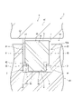
- FIG. 7 is an enlarged partial cross-sectional view showing the vicinity of the protrusion 4 of the seal ring 2 and the recess 3 of the shaft 50 in the sealing structure 1 of the present invention shown in FIG.
- the seal ring 2 is attached to the groove 51 of the shaft 50 and the protrusion 4 is accommodated in the recess 3, the locking surface 43 of the protrusion 4 and the recess 3 are engaged with each other.
- a gap may occur between the stop surface 32 and the stop surface 32 .
- the portion of the outer peripheral surface 22 of the seal ring 2 near the abutment portion 5 does not come into contact with the inner peripheral surface 62 of the shaft hole 61.
- a minute gap S may occur between the outer peripheral surface 22 of the ring 2 and the inner peripheral surface 62 of the shaft hole 61 .
- the gap S between the outer peripheral surface 22 of the seal ring 2 and the inner peripheral surface 62 of the shaft hole 61 disappears.
- the disappearance of the gap S occurs even in the above-described no-pressure or low-pressure environment. That is, it occurs regardless of the magnitude of the hydraulic pressure applied to the seal ring 2 .
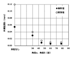
- FIG. 10 also shows the results of a simulation using analysis software (Marc, manufactured by MSC Software Co., Ltd.) that performs FEM (finite element method) analysis.
- analysis software Marc, manufactured by MSC Software Co., Ltd.
- FEM finite element method
- the peripheral gap becomes smaller when the angle ⁇ is 45 degrees or more. Moreover, it was confirmed that when the angle ⁇ is 50 degrees or more (preferably 60 degrees or more), the peripheral gap is particularly small (specifically, the maximum value of the peripheral gap is 0.01 mm or less).
- the angle ⁇ is preferably 80 degrees or less.
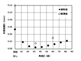
- FIG. 11 also shows simulation results using the same analysis software as in Experiment 1.
- FIG. The simulation was performed for cases of 12 degrees, 22 degrees, 32 degrees, 42 degrees, 52 degrees, 62 degrees, 72 degrees, and 82 degrees with the abutment portion as a reference in the cross section perpendicular to the axis. Moreover, the case where there is no convex portion was also tested. As shown in FIG. 11, the simulation results showed the same tendency as the actual measurement results.
- the outer peripheral gap As shown in FIG. 11, when the center of the circumferential direction of the end face X exists at a position of 20 to 60 degrees (especially about 30 degrees) with respect to the abutment in the cross section perpendicular to the axis, the outer peripheral gap is It was confirmed that the gap becomes smaller (specifically, the maximum value of the outer peripheral gap is 0.01 mm or less).
- sealing structure 2 seal ring 3 concave portion 4 convex portion 5 abutment portion 20 body portion 21 inner peripheral surface 22 outer peripheral surface 23, 24 side surface 3 convex portion 32 locked surface 34, 35 side surface 4 convex portion 43 locking surface 44, 45 side surface 50 shaft 50a outer peripheral surface 51 groove 52 bottom surface 53, 54 side surface 60 housing 61 shaft hole 62 inner peripheral surface R reduction gear S gap L axis line
Landscapes
- Engineering & Computer Science (AREA)
- General Engineering & Computer Science (AREA)
- Mechanical Engineering (AREA)
- Sealing Devices (AREA)
Priority Applications (5)
| Application Number | Priority Date | Filing Date | Title |
|---|---|---|---|
| KR1020237043735A KR20240009496A (ko) | 2021-06-22 | 2022-04-08 | 시일 링 및 그것을 포함한 밀봉 구조체 |
| JP2023529636A JP7510572B2 (ja) | 2021-06-22 | 2022-04-08 | シールリングおよびそれを含む密封構造体 |
| CN202280042887.3A CN117529624A (zh) | 2021-06-22 | 2022-04-08 | 密封环及包含密封环的密封结构体 |
| US18/572,083 US12618473B2 (en) | 2021-06-22 | 2022-04-08 | Sealing ring and sealed structure including same |
| EP22828046.7A EP4361473A4 (en) | 2021-06-22 | 2022-04-08 | SEALING RING AND SEALED STRUCTURE WITH IT |
Applications Claiming Priority (2)
| Application Number | Priority Date | Filing Date | Title |
|---|---|---|---|
| JP2021-102898 | 2021-06-22 | ||
| JP2021102898 | 2021-06-22 |
Publications (1)
| Publication Number | Publication Date |
|---|---|
| WO2022270127A1 true WO2022270127A1 (ja) | 2022-12-29 |
Family
ID=84545582
Family Applications (1)
| Application Number | Title | Priority Date | Filing Date |
|---|---|---|---|
| PCT/JP2022/017399 Ceased WO2022270127A1 (ja) | 2021-06-22 | 2022-04-08 | シールリングおよびそれを含む密封構造体 |
Country Status (5)
| Country | Link |
|---|---|
| EP (1) | EP4361473A4 (https=) |
| JP (1) | JP7510572B2 (https=) |
| KR (1) | KR20240009496A (https=) |
| CN (1) | CN117529624A (https=) |
| WO (1) | WO2022270127A1 (https=) |
Citations (8)
| Publication number | Priority date | Publication date | Assignee | Title |
|---|---|---|---|---|
| JPH0463864U (https=) * | 1990-10-09 | 1992-05-29 | ||
| JP2007292296A (ja) * | 2006-03-30 | 2007-11-08 | Nok Corp | シールリングおよびシールリング製造方法 |
| JP2015218791A (ja) * | 2014-05-15 | 2015-12-07 | Nok株式会社 | シールリング |
| JP2016014481A (ja) | 2014-06-12 | 2016-01-28 | 三菱電線工業株式会社 | シールリング |
| WO2019004268A1 (ja) * | 2017-06-27 | 2019-01-03 | Nok株式会社 | シールリング |
| JP3230072U (ja) * | 2020-10-22 | 2021-01-07 | Tpr株式会社 | シールリング |
| JP2021102898A (ja) | 2019-12-25 | 2021-07-15 | オプテックス株式会社 | ドア開閉制御システム |
| WO2021251319A1 (ja) * | 2020-06-09 | 2021-12-16 | Nok株式会社 | 密封構造 |
Family Cites Families (7)
| Publication number | Priority date | Publication date | Assignee | Title |
|---|---|---|---|---|
| US4681326A (en) * | 1985-06-10 | 1987-07-21 | Cummins Engine Company, Inc. | Gas lubricated piston ring assembly |
| JP5055978B2 (ja) * | 2006-11-29 | 2012-10-24 | Nok株式会社 | シールリング及びシール構造 |
| KR20160014481A (ko) | 2014-07-29 | 2016-02-11 | 삼성전자주식회사 | Idle 모드에서 동작하는 전자 장치 및 방법 |
| KR101983012B1 (ko) * | 2015-05-01 | 2019-05-29 | 생-고뱅 퍼포먼스 플라스틱스 엘+에스 게엠베하 | 밀봉링 |
| JP6601677B2 (ja) * | 2016-02-16 | 2019-11-06 | 三菱日立パワーシステムズ株式会社 | シール装置及び回転機械 |
| DE102018114701A1 (de) * | 2018-06-19 | 2019-12-19 | Konzelmann Gmbh | Hydrodynamisch wirksamer Dichtring und Drehdurchführung mit einem solchen Dichtring |
| JP7595536B2 (ja) | 2020-09-30 | 2024-12-06 | Tpr株式会社 | シールリング及びこのシールリングの装着構造 |
-
2022
- 2022-04-08 CN CN202280042887.3A patent/CN117529624A/zh active Pending
- 2022-04-08 JP JP2023529636A patent/JP7510572B2/ja active Active
- 2022-04-08 KR KR1020237043735A patent/KR20240009496A/ko active Pending
- 2022-04-08 EP EP22828046.7A patent/EP4361473A4/en active Pending
- 2022-04-08 WO PCT/JP2022/017399 patent/WO2022270127A1/ja not_active Ceased
Patent Citations (8)
| Publication number | Priority date | Publication date | Assignee | Title |
|---|---|---|---|---|
| JPH0463864U (https=) * | 1990-10-09 | 1992-05-29 | ||
| JP2007292296A (ja) * | 2006-03-30 | 2007-11-08 | Nok Corp | シールリングおよびシールリング製造方法 |
| JP2015218791A (ja) * | 2014-05-15 | 2015-12-07 | Nok株式会社 | シールリング |
| JP2016014481A (ja) | 2014-06-12 | 2016-01-28 | 三菱電線工業株式会社 | シールリング |
| WO2019004268A1 (ja) * | 2017-06-27 | 2019-01-03 | Nok株式会社 | シールリング |
| JP2021102898A (ja) | 2019-12-25 | 2021-07-15 | オプテックス株式会社 | ドア開閉制御システム |
| WO2021251319A1 (ja) * | 2020-06-09 | 2021-12-16 | Nok株式会社 | 密封構造 |
| JP3230072U (ja) * | 2020-10-22 | 2021-01-07 | Tpr株式会社 | シールリング |
Non-Patent Citations (1)
| Title |
|---|
| See also references of EP4361473A4 |
Also Published As
| Publication number | Publication date |
|---|---|
| US20240288074A1 (en) | 2024-08-29 |
| JP7510572B2 (ja) | 2024-07-03 |
| JPWO2022270127A1 (https=) | 2022-12-29 |
| EP4361473A4 (en) | 2025-05-14 |
| EP4361473A1 (en) | 2024-05-01 |
| CN117529624A (zh) | 2024-02-06 |
| KR20240009496A (ko) | 2024-01-22 |
Similar Documents
| Publication | Publication Date | Title |
|---|---|---|
| JP6314689B2 (ja) | 密封装置 | |
| CN105308370A (zh) | 密封环 | |
| JP6447667B2 (ja) | シールリング及び密封構造 | |
| WO2019004268A1 (ja) | シールリング | |
| WO2022270127A1 (ja) | シールリングおよびそれを含む密封構造体 | |
| JP7377891B2 (ja) | 密封装置 | |
| US12618473B2 (en) | Sealing ring and sealed structure including same | |
| WO2021251319A1 (ja) | 密封構造 | |
| WO2016140056A1 (ja) | シールリング | |
| JP6458905B2 (ja) | シールリング | |
| JP2017133571A (ja) | 密封装置 | |
| JP7153161B2 (ja) | シールリングおよび油圧機器 | |
| JP6865122B2 (ja) | 密封構造 | |
| WO2018163770A1 (ja) | シールリング | |
| JP2017211060A (ja) | 密封構造 | |
| WO2024128135A1 (ja) | シールリング及び密封構造 | |
| JP2017101736A (ja) | シールリング | |
| JP2019094939A (ja) | 密封構造 | |
| JP2020041547A (ja) | シールリング | |
| JP2008144814A (ja) | シールリング及び密封構造 |
Legal Events
| Date | Code | Title | Description |
|---|---|---|---|
| 121 | Ep: the epo has been informed by wipo that ep was designated in this application |
Ref document number: 22828046 Country of ref document: EP Kind code of ref document: A1 |
|
| WWE | Wipo information: entry into national phase |
Ref document number: 202280042887.3 Country of ref document: CN Ref document number: 2023529636 Country of ref document: JP |
|
| ENP | Entry into the national phase |
Ref document number: 20237043735 Country of ref document: KR Kind code of ref document: A |
|
| WWE | Wipo information: entry into national phase |
Ref document number: 1020237043735 Country of ref document: KR |
|
| WWE | Wipo information: entry into national phase |
Ref document number: 18572083 Country of ref document: US |
|
| WWE | Wipo information: entry into national phase |
Ref document number: 2022828046 Country of ref document: EP |
|
| NENP | Non-entry into the national phase |
Ref country code: DE |
|
| ENP | Entry into the national phase |
Ref document number: 2022828046 Country of ref document: EP Effective date: 20240122 |