WO2022269899A1 - ステアリング装置 - Google Patents
ステアリング装置 Download PDFInfo
- Publication number
- WO2022269899A1 WO2022269899A1 PCT/JP2021/024115 JP2021024115W WO2022269899A1 WO 2022269899 A1 WO2022269899 A1 WO 2022269899A1 JP 2021024115 W JP2021024115 W JP 2021024115W WO 2022269899 A1 WO2022269899 A1 WO 2022269899A1
- Authority
- WO
- WIPO (PCT)
- Prior art keywords
- bearing support
- support member
- worm wheel
- housing
- peripheral surface
- Prior art date
- Legal status (The legal status is an assumption and is not a legal conclusion. Google has not performed a legal analysis and makes no representation as to the accuracy of the status listed.)
- Ceased
Links
Images



Classifications
-
- B—PERFORMING OPERATIONS; TRANSPORTING
- B62—LAND VEHICLES FOR TRAVELLING OTHERWISE THAN ON RAILS
- B62D—MOTOR VEHICLES; TRAILERS
- B62D5/00—Power-assisted or power-driven steering
- B62D5/04—Power-assisted or power-driven steering electrical, e.g. using an electric servo-motor connected to, or forming part of, the steering gear
- B62D5/0409—Electric motor acting on the steering column
-
- B—PERFORMING OPERATIONS; TRANSPORTING
- B62—LAND VEHICLES FOR TRAVELLING OTHERWISE THAN ON RAILS
- B62D—MOTOR VEHICLES; TRAILERS
- B62D5/00—Power-assisted or power-driven steering
- B62D5/04—Power-assisted or power-driven steering electrical, e.g. using an electric servo-motor connected to, or forming part of, the steering gear
- B62D5/0442—Conversion of rotational into longitudinal movement
- B62D5/0454—Worm gears
-
- B—PERFORMING OPERATIONS; TRANSPORTING
- B62—LAND VEHICLES FOR TRAVELLING OTHERWISE THAN ON RAILS
- B62D—MOTOR VEHICLES; TRAILERS
- B62D5/00—Power-assisted or power-driven steering
- B62D5/04—Power-assisted or power-driven steering electrical, e.g. using an electric servo-motor connected to, or forming part of, the steering gear
- B62D5/0403—Power-assisted or power-driven steering electrical, e.g. using an electric servo-motor connected to, or forming part of, the steering gear characterised by constructional features, e.g. common housing for motor and gear box
-
- B—PERFORMING OPERATIONS; TRANSPORTING
- B62—LAND VEHICLES FOR TRAVELLING OTHERWISE THAN ON RAILS
- B62D—MOTOR VEHICLES; TRAILERS
- B62D6/00—Arrangements for automatically controlling steering depending on driving conditions sensed and responded to, e.g. control circuits
- B62D6/08—Arrangements for automatically controlling steering depending on driving conditions sensed and responded to, e.g. control circuits responsive only to driver input torque
- B62D6/10—Arrangements for automatically controlling steering depending on driving conditions sensed and responded to, e.g. control circuits responsive only to driver input torque characterised by means for sensing or determining torque
Definitions
- the present disclosure relates to steering devices.
- the steering device of Patent Document 1 has a motor and a metal housing.
- a housing contains a torque sensor and a worm gear mechanism.
- the motor generates torque corresponding to the steering torque detected by the torque sensor. Torque of the motor is transmitted to the steering shaft through a worm gear mechanism.
- the housing has a worm housing member and a sensor housing member.
- a worm housing member houses the worm gear mechanism.
- a sensor housing member houses the torque sensor.
- the worm housing member and the sensor housing member are fitted together in the axial direction of the steering shaft.
- the steering shaft is rotatably supported by the worm housing member and the sensor housing member via bearings.
- a steering device includes a cylindrical support cylinder having a flange and rotatably supporting a steering shaft, a speed reducer configured to apply torque to the steering shaft, and the speed reducer.
- a housing having a cylindrical portion for accommodating a machine, the cylindrical portion being arranged coaxially with the flange; bolts connecting the flange and the cylindrical portion to each other;
- the bearing support member includes a bearing support member through which the steering shaft passes, and a bearing interposed between an outer peripheral surface of the steering shaft and an inner peripheral surface of the bearing support member.
- the bearing support member and the cylindrical portion have engaging portions that engage each other in the axial direction of the bearing support member.
- FIG. 1 is a schematic diagram showing the configuration of an embodiment of a steering device
- FIG. FIG. 2 is a perspective view of the steering column of FIG. 1
- FIG. 3 is a cross-sectional view of a connecting portion between the housing and the lower tube in FIG. 2; The perspective view which looked at the intermediate
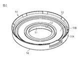
- FIG. 4 is a perspective view of the intermediate plate of FIG. 3 as seen obliquely from below;
- the steering device 1 has a steering shaft 2, an intermediate shaft 3, a pinion shaft 4, and a rack shaft 5.
- a steering wheel 6 is connected to a first end of the steering shaft 2 .
- a first end of the intermediate shaft 3 is connected to a second end of the steering shaft 2 via a universal joint 7 .
- a first end of the pinion shaft 4 is connected to a second end of the intermediate shaft 3 via a universal joint 8 .
- a pinion 4 a is provided at the second end of the pinion shaft 4 .
- the pinion 4 a meshes with a rack 5 a provided on the rack shaft 5 .
- the rack shaft 5 is supported inside a housing 10 fixed to a frame 9 of the vehicle body.
- the steering shaft 2 has an outer shaft 11 and an inner shaft 12. Outer shaft 11 and inner shaft 12 are connected to each other by, for example, a spline connection. The outer shaft 11 and the inner shaft 12 are rotatable together and axially movable relative to each other. The steering shaft 2 is provided obliquely with respect to the front-rear direction of the vehicle with the steering wheel 6 facing upward.
- the steering device 1 has a steering column 15 .
- a steering shaft 2 is inserted through the steering column 15 .
- the steering shaft 2 is rotatably supported with respect to the steering column 15 via bearings (not shown).
- the steering column 15 is attached to two frames 13 and 14 provided on the vehicle body. One frame 13 is located behind the other frame 14 in the longitudinal direction of the vehicle.
- the steering column 15 has an upper tube 16, a lower tube 17 and a housing 18.
- Upper tube 16 is cylindrical.
- the lower tube 17 is cylindrical and has a flange 31 .
- the upper tube 16 and the lower tube 17 are fitted together.
- upper tube 16 is inserted into a first end of lower tube 17 .
- the first end is the end opposite the second end where the flange 31 is provided.
- the upper tube 16 and the lower tube 17 are relatively movable in the axial direction of the steering shaft 2 .
- the lower tube 17 has a column bracket 17A.
- the lower tube 17 is attached to the vehicle body frame 13 via a column bracket 17A.
- the upper tube 16 and the lower tube 17 constitute a support tube that rotatably supports the steering shaft 2.
- the housing 18 is connected to the second end of the lower tube 17.
- the housing 18 has two support portions 18A (only one is shown in FIG. 1) and a support shaft 18B.
- the two support portions 18A are provided on the side surface of the housing 18 opposite to the lower tube 17. As shown in FIG.
- the two support portions 18A face each other in the width direction of the vehicle body.
- the support shaft 18B extends between the two support portions 18A.
- the support shaft 18B is rotatably connected to a bracket 24 fixed to the frame 14 of the vehicle body.
- a motor 19 for steering assistance is provided outside the housing 18 .
- a speed reducer 20 is housed inside the housing 18 .
- the speed reducer 20 reduces the rotation of the motor 19 and transmits the reduced rotation to the inner shaft 12 .
- the speed reducer 20 is a worm speed reducer having a worm 21 and a worm wheel 22 .
- the worm 21 is connected to an output shaft (not shown) of the motor 19 so as to rotate integrally therewith.
- the axis of the worm 21 and the axis of the output shaft of the motor 19 are positioned on the same straight line.
- a worm wheel 22 meshes with the worm 21 .
- the worm wheel 22 is provided so as to be rotatable together with the inner shaft 12 .
- the axis of the worm wheel 22 and the axis of the inner shaft 12 are positioned on the same straight line.
- the steering device 1 has a lock mechanism (not shown).
- the lock mechanism selectively locks and unlocks swinging of the steering column 15 about the support shaft 18B and expansion and contraction of the steering column 15 through operation of a lever (not shown).
- a lever not shown
- the steering column 15 can swing about the support shaft 18B with respect to the column bracket 17A.
- the upper tube 16 can move in the axial direction of the steering shaft 2 with respect to the lower tube 17 .
- the position of the steering wheel 6 in the axial direction can be adjusted.
- the lower tube 17 has a flange 31 as shown in FIG.
- a flange 31 is provided at the second end of the lower tube 17 .
- the second end of the lower tube 17 is the end opposite to the first end into which the upper tube 16 is inserted.
- the flange 31 is an annular flat plate.
- the flange 31 has two mounting portions 31A.
- the two mounting portions 31A are provided on the outer peripheral surface of the flange 31 .
- the two mounting portions 31A protrude radially outward from the outer peripheral surface of the flange 31 .
- the two mounting portions 31A are located on opposite sides of the flange 31 in the radial direction.
- the two mounting portions 31A each have an insertion hole 31B.
- the bolt 30 is inserted through the insertion hole 31B.
- the flange 31 is fixed to the housing 18 by tightening the bolt 30 to the housing 18 .
- Bolt 30 has a head portion 30A and a shaft portion 30B.
- the housing 18 has a worm wheel housing member 41 and a worm housing member 42.
- the worm wheel housing member 41 and the worm housing member 42 are each cylindrical.
- the worm housing member 42 is connected to the outer peripheral surface of the worm wheel housing member 41 .
- the worm housing member 42 extends in a direction perpendicular to the axis of the worm wheel housing member 41 .
- the inside of the worm wheel housing member 41 and the inside of the worm housing member 42 communicate with each other through a communication hole (not shown).
- a worm wheel housing member 41 constitutes the cylindrical portion of the housing 18 .
- the housing 18 is made of metal such as aluminum.
- the worm wheel 22 is rotatably accommodated inside the worm wheel housing member 41 .
- the worm 21 is rotatably supported inside the worm housing member 42 via a bearing (not shown).
- the worm wheel 22 and the worm 21 mesh with each other through the communicating holes provided inside the housing 18 .
- the worm wheel housing member 41 has an opening 41A at a first end in the axial direction and an end wall at a second end opposite to the first end. doing.
- the opening 41 ⁇ /b>A opens toward the lower tube 17 along the axis of the worm wheel housing member 41 .
- the outer diameter of the worm wheel housing member 41 is substantially the same as the outer diameter of the flange 31 .
- the worm wheel housing member 41 has a cylindrical bearing support portion 43 .
- the bearing support portion 43 is provided on the end wall of the worm wheel housing member 41 .
- the opening 41A and the bearing support 43 are arranged coaxially.
- the inside of the worm wheel housing member 41 and the outside of the worm wheel housing member 41 communicate with each other via the bearing support portion 43 .
- the worm wheel housing member 41 has two tightening portions 44 .
- Each tightening portion 44 is a portion to which the bolt 30 is tightened when fixing the flange 31 to the housing 18 .
- Each fastening portion 44 protrudes radially outward from the outer peripheral surface of the worm wheel housing member 41 .
- the two tightening portions 44 are located on opposite sides of the worm wheel housing member 41 in the radial direction.
- Each fastening portion 44 has a threaded hole 44A. The end face of each tightening portion 44 where the screw hole 44A opens is flush with the end face of the worm wheel housing member 41 where the opening 41A opens.
- the peripheral edge of the flange 31 is in contact with the end face of the worm wheel housing member 41 where the opening 41A opens.
- the insertion hole 31B of the flange 31 and the threaded hole 44A of the housing 18 are aligned with each other.
- the bolt 30 is inserted through the insertion hole 31B of the flange 31 from the opposite side of the housing 18 .
- This bolt 30 is tightened to the tightening portion 44 of the housing 18 .
- the flange 31 is thereby fixed to the housing 18 . That is, the lower tube 17 is connected to the housing 18 via the flange 31 .
- the opening 41A of the housing 18 is closed by the flange 31 .
- the flange 31 also serves as a cover that closes the opening 41A of the housing 18. As shown in FIG.
- the worm wheel housing member 41 rotatably supports the inner shaft 12.
- the inner shaft 12 passes through the worm wheel housing member 41 .
- the axis of the inner shaft 12 and the axis of the worm wheel housing member 41 are positioned on the same straight line.
- the inner shaft 12 has an input shaft 12A, an output shaft 12B and a torsion bar 12C.
- the input shaft 12A and the output shaft 12B are connected to each other via a torsion bar 12C.
- the output shaft 12B is a hollow cylinder.
- a first end of the input shaft 12A is connected to the outer shaft 11.
- the second end of input shaft 12A is inserted into the first end of output shaft 12B.
- a slide bearing 12D is interposed between the outer peripheral surface of the input shaft 12A and the inner peripheral surface of the output shaft 12B. The input shaft 12A and the output shaft 12B can relatively rotate via a sliding bearing 12D.
- a first end of the torsion bar 12C is inserted and fixed to the second end of the input shaft 12A.
- a second end of the torsion bar 12C is inserted inside the output shaft 12B.
- a second end of the torsion bar 12C is fixed to a second end of the output shaft 12B.
- a steering torque applied to the steering wheel 6 is transmitted to the output shaft 12B via the input shaft 12A and the torsion bar 12C.
- the torsion bar 12C is twisted according to the steering torque.
- the worm wheel 22 and the bearing support member 50 are housed inside the worm wheel housing member 41 .
- the worm wheel 22 is fixed to the outer peripheral surface of the output shaft 12B so as to be rotatable therewith.
- the bearing support member 50 has a cylindrical shape and is mounted rotatably relative to the outer peripheral surface of the output shaft 12B.
- the worm wheel 22 and the bearing support member 50 are spaced apart from each other along the axial direction of the worm wheel housing member 41 .
- the worm wheel 22 is arranged between the bearing support member 50 and the end wall of the worm wheel housing member 41 .
- the worm wheel housing member 41, the worm wheel 22 and the bearing support member 50 are arranged coaxially.
- the bearing support member 50 has a peripheral wall 50A and an end wall 50B extending radially inward from a first axial end of the peripheral wall 50A.
- the peripheral wall 50A has a second end, which is an open end, opposite to the first end.
- the bearing support member 50 has an insertion hole 51 .
- the insertion hole 51 penetrates through the center of the end wall 50B of the bearing support member 50 .
- An annular inward projection 52 is provided on the inner peripheral surface of the end wall 50B. The inward projection 52 extends in the circumferential direction along the inner peripheral surface of the bearing support member 50, more specifically along the inner peripheral surface of the end wall 50B.
- the inward projection 52 is flush with the inner surface of the end wall 50B of the bearing support member 50 .
- the bearing support member 50 also has an annular outward projection 53 .
- the outward projection 53 is provided at the axial end of the bearing support member 50, more specifically at the second end of the peripheral wall 50A.
- the outward protrusion 53 extends in the circumferential direction along the outer peripheral surface of the peripheral wall 50A.
- the outward projection 53 is inclined so as to approach the flange 31 toward the radially outer side of the bearing support member 50 .
- the bearing support member 50 is made of synthetic resin, for example. That is, the linear expansion coefficients of the bearing support member 50 and the housing 18 are different from each other.
- the coefficient of linear expansion of synthetic resin is larger than the coefficient of linear expansion of metal.
- the outer peripheral surface of the bearing support member 50 that is, the outer peripheral surface of the end wall 50B fits into the inner peripheral surface of the worm wheel housing member 41.
- the bearing support member 50 has a corner portion 54 formed at the intersection of the end wall 50B and the peripheral wall 50A.
- the corner portion 54 is in contact with the annular stepped portion 45 provided on the inner peripheral surface of the worm wheel housing member 41 in the mounting direction DW.
- the mounting direction DW is the direction along the axis of the worm wheel housing member 41 and the direction in which the bearing support member 50 is inserted into the worm wheel housing member 41 .
- the stepped portion 45 is provided at a portion where the inner diameter of the worm wheel housing member 41 changes, and extends in the circumferential direction along the inner peripheral surface of the worm wheel housing member 41 .
- the contact of the corner portion 54 with the stepped portion 45 restricts the movement of the bearing support member 50 with respect to the worm wheel housing member 41 in the mounting direction DW.
- the outward projection 53 is hooked in an annular groove 46 provided on the inner peripheral surface of the worm wheel housing member 41 .
- the groove 46 extends circumferentially along the inner peripheral surface of the worm wheel housing member 41 .
- the outward projection 53 abuts against the groove 46 in the direction opposite to the mounting direction DW, thereby restricting the movement of the bearing support member 50 with respect to the worm wheel housing member 41 in the direction opposite to the mounting direction DW.
- the output shaft 12B is rotatably supported on the inner peripheral surface of the bearing support portion 43 via the bearing 61.
- the bearing 61 is in a state where axial movement is restricted.
- An annular stepped portion 62 and a retaining ring 63 are provided on the outer peripheral surface of the output shaft 12B.
- the inner ring of bearing 61 is interposed between stepped portion 62 and retaining ring 63 .
- An annular protrusion 64 and a retaining ring 65 are provided on the inner peripheral surface of the bearing support portion 43 .
- the outer ring of bearing 61 is interposed between protrusion 64 and retaining ring 65 .
- the output shaft 12B is rotatably supported in the insertion hole 51 of the bearing support member 50 via the bearing 71.
- the bearing 71 is in a state where axial movement is restricted.
- An annular ridge 72 is provided on the outer peripheral surface of the output shaft 12B.
- the inner ring of the bearing 71 is in contact with the ridge 72 in the mounting direction DW.
- the outer ring of the bearing 71 is in contact with the annular inward projection 52 of the bearing support member 50 in the direction opposite to the mounting direction DW.
- the inner space of the worm wheel housing member 41 is partitioned into two spaces by the bearing support member 50 .
- a sensor 80 is provided in the space between the bearing support member 50 and the flange 31 .
- Sensor 80 includes a torque sensor and a rotation angle sensor.
- the torque sensor detects steering torque based on the twist amount of the torsion bar 12C.
- the rotation angle sensor detects the rotation angle of the input shaft 12A as the steering angle.
- the space between the bearing support member 50 and the end wall of the worm wheel housing member 41 is filled with grease.
- a steering device having the following housing.
- a conventional housing has, for example, a worm housing member that houses a speed reducer and a cylindrical sensor housing member that houses a sensor.
- the steering shaft is rotatably supported by a bearing provided on the worm housing member and a bearing provided on the sensor housing member.
- a tubular member containing the steering shaft is attached to the sensor housing member. This cylindrical member corresponds to the lower tube 17 of this embodiment.
- the bearing support member 50 which is a member for supporting the bearing 71
- the flange 31, which is a member for connecting the lower tube 17 to the housing 18, are independent of each other. It is provided as a component.
- the bearing support member 50 is mounted inside the worm wheel housing member 41 .
- the lower tube 17 is fixed to the worm wheel housing member 41 via the flange 31 .
- the lower tube 17 is directly fixed to the worm wheel housing member 41 via the plate-shaped flange 31 . Therefore, compared to the case where the lower tube 17 is attached to the worm wheel housing member 41 through a structure corresponding to a conventional sensor housing member, the size of the steering column 15 can be reduced in the axial direction.
- the bearing support member 50 is kept fitted to the inner peripheral surface of the worm wheel housing member 41 . Fastening parts such as bolts for fixing the bearing support member 50 to the worm wheel housing member 41 are unnecessary. Therefore, the number of parts can be reduced.
- the bearing support member 50 is maintained in a state in which axial movement is restricted.
- the outward ridge 53 and the groove 46 which are engaging portions, engage with each other in the axial direction of the bearing support member 50, thereby restricting the movement of the bearing support member 50 in the direction opposite to the mounting direction DW.
- the corner portion 54 and the stepped portion 45 which are the engaging portions, are engaged with each other in the axial direction of the bearing support member 50, or the inward projection 52 and the outer ring of the bearing 71 are engaged with each other in the axial direction of the bearing support member 50.
- movement of the bearing support member 50 in the mounting direction DW is restricted. Therefore, it is possible to prevent the bearing support member 50 from slipping off from the bearing 71 in the axial direction. Therefore, the bearing support member 50 is maintained in a state in which the bearing 71 is favorably supported. Furthermore, since the bearing support member 50 can be assembled to the worm wheel housing member 41 from the mounting direction DW with one touch, the assembling property is improved.
- the linear expansion coefficients of the bearing support member 50 and the housing 18 are different from each other. Therefore, the bearing support member 50 and the housing 18 differ in the degree of dimensional change with respect to changes in ambient temperature. For example, if the coefficient of linear expansion of the bearing support member 50 is larger than that of the housing 18, the bearing support member 50 may shrink more than the housing 18 as the ambient temperature drops. As the bearing support member 50 shrinks in the radial direction, there is concern that a gap may be formed between the outer peripheral surface of the bearing support member 50 and the inner peripheral surface of the worm wheel housing member 41 .
- the engagement between the outward projection 53 and the groove 46 is minimized.
- the movement of the bearing support member 50 in the direction opposite to the mounting direction DW is restricted unless the engagement is released. Further, the movement of the bearing support member 50 in the mounting direction DW is restricted unless the engagement between the corner portion 54 and the stepped portion 45 or the engagement between the inward projection 52 and the outer ring of the bearing 71 is released. Therefore, the bearing support member 50 is maintained in a state of supporting the bearing 71 .
- the worm wheel 22, the bearing support member 50, and the sensor 80 can be arranged within the housing 18, there is no need to house the sensor in a sensor housing member separate from the conventional worm housing member. Therefore, the ease of assembly is improved. Furthermore, since the worm wheel 22, the bearing support member 50, and the sensor 80 can be assembled to the worm wheel housing member 41 from one direction in the mounting direction DW, the assembling efficiency is improved.
- the bearing support member 50 and the housing 18 are appropriately changed according to product specifications.
- the bearing support member 50 may be made of metal and the housing 18 may be made of synthetic resin.
- the bearing support member 50 and the housing 18 may be made of the same material. In this case, the bearing support member 50 and the housing 18 have the same coefficient of linear expansion. Therefore, bearing support member 50 and housing 18 undergo similar dimensional changes with changes in ambient temperature. Therefore, a gap is less likely to occur between the outer peripheral surface of the bearing support member 50 and the inner peripheral surface of the worm wheel housing member 41 .
- a configuration in which the stepped portion 45 is omitted from the worm wheel housing member 41 may be adopted. Even in this manner, the inward projection 52 of the bearing support member 50 and the outer ring of the bearing 71 are engaged with each other, thereby restricting the movement of the bearing support member 50 in the mounting direction DW.
- a configuration in which the annular inward projection 52 is omitted from the bearing support member 50 may be adopted. Even in this manner, the movement of the bearing support member 50 in the mounting direction DW is restricted by the mutual engagement between the corner portion 54 of the bearing support member 50 and the stepped portion 45 of the worm wheel housing member 41 .
- the steering device 1 may not be provided with a configuration for adjusting the vertical position of the steering wheel 6 and a configuration for adjusting the axial position of the steering wheel 6 .
- a single non-stretchable support cylinder is provided instead of the upper tube 16 and the lower tube 17.
- the single support cylinder rotatably supports the steering shaft 2 .
- the housing 18 is fixed to the frame 14 of the vehicle body. A configuration in which the support portion 18A and the support shaft 18B are omitted from the housing 18 can be adopted. Further, a lock mechanism for selectively locking and unlocking the pivoting of the steering column 15 about the support shaft 18B and the expansion and contraction of the steering column 15 is not necessary.
Landscapes
- Engineering & Computer Science (AREA)
- Chemical & Material Sciences (AREA)
- Combustion & Propulsion (AREA)
- Transportation (AREA)
- Mechanical Engineering (AREA)
- Power Steering Mechanism (AREA)
Priority Applications (6)
| Application Number | Priority Date | Filing Date | Title |
|---|---|---|---|
| PCT/JP2021/024115 WO2022269899A1 (ja) | 2021-06-25 | 2021-06-25 | ステアリング装置 |
| CN202280043603.2A CN117500716B (zh) | 2021-06-25 | 2022-02-09 | 转向装置 |
| JP2023529486A JP7642812B2 (ja) | 2021-06-25 | 2022-02-09 | ステアリング装置 |
| EP22826644.1A EP4360997A4 (en) | 2021-06-25 | 2022-02-09 | STEERING DEVICE |
| PCT/JP2022/005174 WO2022269986A1 (ja) | 2021-06-25 | 2022-02-09 | ステアリング装置 |
| US18/571,861 US20240286670A1 (en) | 2021-06-25 | 2022-02-09 | Steering device |
Applications Claiming Priority (1)
| Application Number | Priority Date | Filing Date | Title |
|---|---|---|---|
| PCT/JP2021/024115 WO2022269899A1 (ja) | 2021-06-25 | 2021-06-25 | ステアリング装置 |
Publications (1)
| Publication Number | Publication Date |
|---|---|
| WO2022269899A1 true WO2022269899A1 (ja) | 2022-12-29 |
Family
ID=84543734
Family Applications (2)
| Application Number | Title | Priority Date | Filing Date |
|---|---|---|---|
| PCT/JP2021/024115 Ceased WO2022269899A1 (ja) | 2021-06-25 | 2021-06-25 | ステアリング装置 |
| PCT/JP2022/005174 Ceased WO2022269986A1 (ja) | 2021-06-25 | 2022-02-09 | ステアリング装置 |
Family Applications After (1)
| Application Number | Title | Priority Date | Filing Date |
|---|---|---|---|
| PCT/JP2022/005174 Ceased WO2022269986A1 (ja) | 2021-06-25 | 2022-02-09 | ステアリング装置 |
Country Status (4)
| Country | Link |
|---|---|
| US (1) | US20240286670A1 (https=) |
| EP (1) | EP4360997A4 (https=) |
| JP (1) | JP7642812B2 (https=) |
| WO (2) | WO2022269899A1 (https=) |
Citations (2)
| Publication number | Priority date | Publication date | Assignee | Title |
|---|---|---|---|---|
| JP2008184043A (ja) * | 2007-01-30 | 2008-08-14 | Nsk Ltd | 電動パワーステアリング装置およびその製造方法 |
| WO2014069423A1 (ja) * | 2012-10-29 | 2014-05-08 | 日本精工株式会社 | 電動式パワーステアリング装置 |
Family Cites Families (4)
| Publication number | Priority date | Publication date | Assignee | Title |
|---|---|---|---|---|
| CN102112363B (zh) * | 2008-08-01 | 2013-07-10 | 株式会社捷太格特 | 电动动力转向装置 |
| EP2921372A4 (en) * | 2012-11-15 | 2016-11-02 | Nsk Ltd | ELECTRIC POWER STEERING SYSTEM |
| JP2016211615A (ja) * | 2015-04-30 | 2016-12-15 | 株式会社ジェイテクト | ウォーム減速機およびステアリング装置 |
| JP2020090139A (ja) | 2018-12-04 | 2020-06-11 | 株式会社ジェイテクト | ステアリング装置の制御装置 |
-
2021
- 2021-06-25 WO PCT/JP2021/024115 patent/WO2022269899A1/ja not_active Ceased
-
2022
- 2022-02-09 US US18/571,861 patent/US20240286670A1/en active Pending
- 2022-02-09 JP JP2023529486A patent/JP7642812B2/ja active Active
- 2022-02-09 WO PCT/JP2022/005174 patent/WO2022269986A1/ja not_active Ceased
- 2022-02-09 EP EP22826644.1A patent/EP4360997A4/en active Pending
Patent Citations (2)
| Publication number | Priority date | Publication date | Assignee | Title |
|---|---|---|---|---|
| JP2008184043A (ja) * | 2007-01-30 | 2008-08-14 | Nsk Ltd | 電動パワーステアリング装置およびその製造方法 |
| WO2014069423A1 (ja) * | 2012-10-29 | 2014-05-08 | 日本精工株式会社 | 電動式パワーステアリング装置 |
Also Published As
| Publication number | Publication date |
|---|---|
| WO2022269986A1 (ja) | 2022-12-29 |
| JP7642812B2 (ja) | 2025-03-10 |
| EP4360997A1 (en) | 2024-05-01 |
| JPWO2022269986A1 (https=) | 2022-12-29 |
| CN117500716A (zh) | 2024-02-02 |
| US20240286670A1 (en) | 2024-08-29 |
| EP4360997A4 (en) | 2024-10-23 |
Similar Documents
| Publication | Publication Date | Title |
|---|---|---|
| US8727065B2 (en) | Electric power steering device | |
| US20070295552A1 (en) | Electric power steering apparatus | |
| US10556616B2 (en) | Damping coupler of electronic power steering apparatus | |
| KR102693164B1 (ko) | 스티어 바이 와이어식 조향장치 | |
| KR20230114438A (ko) | 자동차의 조향장치 | |
| US20230406403A1 (en) | Steering actuator and initial free play adjustment method between reducer gears of steering actuator | |
| JP5397653B2 (ja) | 車両用操舵装置 | |
| WO2022269899A1 (ja) | ステアリング装置 | |
| US20080179131A1 (en) | Variable gear ratio steering apparatus | |
| JP7472595B2 (ja) | ステアリング装置 | |
| KR102350046B1 (ko) | 자동차의 조향 컬럼 | |
| JP5262592B2 (ja) | 車両用操舵力伝達装置 | |
| JP7790549B2 (ja) | ステアリング装置 | |
| JP7779935B2 (ja) | 回転制限装置およびステアリング装置 | |
| JP2011046310A (ja) | 車両用操舵装置 | |
| US20240286665A1 (en) | Steering device | |
| US11433940B2 (en) | Electromechanical power steering system having a helical gear mechanism and having a compensation device for supporting a floating bearing on the gear housing | |
| JP5281353B2 (ja) | 車両用操舵力伝達装置 | |
| JP2009166684A (ja) | 電動パワーステアリング装置用の電動アシスト機構 | |
| JP5212714B2 (ja) | 車両用衝撃吸収操舵装置 | |
| JP2007050845A (ja) | 電動パワーステアリング装置 | |
| JP7783775B2 (ja) | 回転制限装置およびステアリング装置 | |
| JP7529910B2 (ja) | ステアリング装置 | |
| JP2024093325A (ja) | ステアリング装置 | |
| JP5397659B2 (ja) | 車両用操舵装置 |
Legal Events
| Date | Code | Title | Description |
|---|---|---|---|
| 121 | Ep: the epo has been informed by wipo that ep was designated in this application |
Ref document number: 21947182 Country of ref document: EP Kind code of ref document: A1 |
|
| NENP | Non-entry into the national phase |
Ref country code: DE |
|
| 122 | Ep: pct application non-entry in european phase |
Ref document number: 21947182 Country of ref document: EP Kind code of ref document: A1 |
|
| NENP | Non-entry into the national phase |
Ref country code: JP |