WO2022269730A1 - Dispositif d'irradiation de lumière et procédé de commande pour dispositif d'irradiation de lumière - Google Patents
Dispositif d'irradiation de lumière et procédé de commande pour dispositif d'irradiation de lumière Download PDFInfo
- Publication number
- WO2022269730A1 WO2022269730A1 PCT/JP2021/023495 JP2021023495W WO2022269730A1 WO 2022269730 A1 WO2022269730 A1 WO 2022269730A1 JP 2021023495 W JP2021023495 W JP 2021023495W WO 2022269730 A1 WO2022269730 A1 WO 2022269730A1
- Authority
- WO
- WIPO (PCT)
- Prior art keywords
- light
- identification
- output ports
- therapeutic
- unit
- Prior art date
Links
- 238000000034 method Methods 0.000 title claims description 65
- 230000001225 therapeutic effect Effects 0.000 claims description 152
- 238000011282 treatment Methods 0.000 claims description 90
- 230000003287 optical effect Effects 0.000 claims description 84
- 238000001514 detection method Methods 0.000 claims description 46
- 230000008569 process Effects 0.000 claims description 39
- 229940079593 drug Drugs 0.000 claims description 27
- 239000003814 drug Substances 0.000 claims description 27
- 230000001678 irradiating effect Effects 0.000 claims description 15
- 239000003504 photosensitizing agent Substances 0.000 claims description 11
- 206010028980 Neoplasm Diseases 0.000 description 34
- 201000011510 cancer Diseases 0.000 description 34
- 239000000126 substance Substances 0.000 description 31
- 210000004027 cell Anatomy 0.000 description 15
- 238000006552 photochemical reaction Methods 0.000 description 12
- 230000002093 peripheral effect Effects 0.000 description 10
- 230000008859 change Effects 0.000 description 8
- 238000010586 diagram Methods 0.000 description 7
- 238000009792 diffusion process Methods 0.000 description 6
- 230000004048 modification Effects 0.000 description 6
- 238000012986 modification Methods 0.000 description 6
- 238000002360 preparation method Methods 0.000 description 6
- 239000013307 optical fiber Substances 0.000 description 4
- 238000002834 transmittance Methods 0.000 description 4
- 239000000427 antigen Substances 0.000 description 3
- 102000036639 antigens Human genes 0.000 description 3
- 108091007433 antigens Proteins 0.000 description 3
- 230000000694 effects Effects 0.000 description 3
- 230000005284 excitation Effects 0.000 description 3
- 230000006870 function Effects 0.000 description 3
- 239000011521 glass Substances 0.000 description 3
- 210000000170 cell membrane Anatomy 0.000 description 2
- 239000003795 chemical substances by application Substances 0.000 description 2
- 239000004020 conductor Substances 0.000 description 2
- 239000004973 liquid crystal related substance Substances 0.000 description 2
- 239000000463 material Substances 0.000 description 2
- 230000004044 response Effects 0.000 description 2
- 210000001015 abdomen Anatomy 0.000 description 1
- 238000010521 absorption reaction Methods 0.000 description 1
- 210000004100 adrenal gland Anatomy 0.000 description 1
- 230000001174 ascending effect Effects 0.000 description 1
- 230000004397 blinking Effects 0.000 description 1
- 229960005395 cetuximab Drugs 0.000 description 1
- 210000000038 chest Anatomy 0.000 description 1
- 210000001035 gastrointestinal tract Anatomy 0.000 description 1
- 210000003128 head Anatomy 0.000 description 1
- 230000010365 information processing Effects 0.000 description 1
- 210000004185 liver Anatomy 0.000 description 1
- 210000003739 neck Anatomy 0.000 description 1
- 102000004169 proteins and genes Human genes 0.000 description 1
- 108090000623 proteins and genes Proteins 0.000 description 1
- 239000004065 semiconductor Substances 0.000 description 1
- 210000001835 viscera Anatomy 0.000 description 1
- XLYOFNOQVPJJNP-UHFFFAOYSA-N water Substances O XLYOFNOQVPJJNP-UHFFFAOYSA-N 0.000 description 1
Images


Classifications
-
- A—HUMAN NECESSITIES
- A61—MEDICAL OR VETERINARY SCIENCE; HYGIENE
- A61N—ELECTROTHERAPY; MAGNETOTHERAPY; RADIATION THERAPY; ULTRASOUND THERAPY
- A61N5/00—Radiation therapy
- A61N5/06—Radiation therapy using light
- A61N5/0613—Apparatus adapted for a specific treatment
- A61N5/062—Photodynamic therapy, i.e. excitation of an agent
-
- A—HUMAN NECESSITIES
- A61—MEDICAL OR VETERINARY SCIENCE; HYGIENE
- A61N—ELECTROTHERAPY; MAGNETOTHERAPY; RADIATION THERAPY; ULTRASOUND THERAPY
- A61N5/00—Radiation therapy
- A61N5/06—Radiation therapy using light
- A61N5/0601—Apparatus for use inside the body
-
- A—HUMAN NECESSITIES
- A61—MEDICAL OR VETERINARY SCIENCE; HYGIENE
- A61N—ELECTROTHERAPY; MAGNETOTHERAPY; RADIATION THERAPY; ULTRASOUND THERAPY
- A61N5/00—Radiation therapy
- A61N5/06—Radiation therapy using light
- A61N2005/063—Radiation therapy using light comprising light transmitting means, e.g. optical fibres
Definitions
- the present invention relates to a light irradiation device and a control method for the light irradiation device.
- the above International Publication No. 2021/038913 discloses a light irradiation device used for treatment by photoimmunotherapy.
- a drug containing a fluorescent substance that causes a photochemical reaction and an antibody that selectively binds to cancer cells is administered into the body of a cancer patient. It is a treatment method that destroys cancer cells by irradiating them to generate a photochemical reaction.
- the light irradiation device includes an excitation light source that irradiates light of a specific wavelength band (hereinafter referred to as therapeutic light) corresponding to a fluorescent substance, and an optical fiber that guides the therapeutic light to cancer cells.
- a plurality of optical fibers for guiding treatment light from the excitation light source may be used depending on the size of the treatment target site.
- the optical fiber is a thin and long cable-like light guide member that is routed from the light output port of the excitation light source to the patient. Therefore, when a plurality of light guide members are used, each light guide member is connected to which light output port because the plurality of light guide members are entangled with each other between the light output port and the patient. can be difficult to identify. If it is not known to which light output port the light guide member is connected, it is necessary to set the intensity of the therapeutic light emitted from each light guide member and to ensure that the intensity of the therapeutic light matches the set value. It becomes difficult to adjust the
- the therapeutic light emitted from the light guide member is a high-intensity (high-output) laser beam
- workers involved in treatment must block light in the wavelength band including the therapeutic light in order to protect their eyes from the laser beam. You need to wear goggles that do. Therefore, even if the therapeutic light is emitted from the light guide member in order to check the connection with each light output port, it is difficult to visually recognize the therapeutic light through the goggles. Therefore, prior to the treatment, a troublesome task of removing the entanglement of the plurality of light guide members is required, which is inconvenient in that the preparation time required before the start of the treatment is long.
- the present invention has been made to solve the above-described problems, and one object of the present invention is to easily identify to which optical output port each light guide member is connected. It is an object of the present invention to provide a light irradiation device and a control method of the light irradiation device that can
- a light irradiation device is a light irradiation device for irradiating therapeutic light onto a region to be treated of a subject to which a drug containing a photosensitizer has been administered.
- a light source unit including a plurality of light output ports, configured to emit therapeutic light and identification light having a lower intensity than the therapeutic light from each of the plurality of light output ports; a plurality of light guide members each having an incident end connected to one of the light output ports and an emitting end for emitting light incident from the incident end; By emitting identification light from each of the plurality of light output ports, control is performed to identifiably light the plurality of light guide members connected to each of the plurality of light output ports.
- a method for controlling a light irradiation device is a method for controlling a light irradiation device for irradiating a treatment target region of a subject to which a drug containing a photosensitizer is administered with therapeutic light,
- the plurality of light guide members connected to each of the plurality of light guide members are emitted from each of the plurality of light output ports to which the plurality of light guide members are connected, by emitting identification light having an intensity lower than that of the therapeutic light. illuminating in an identifiable manner; and emitting therapeutic light from each of a plurality of light output ports.
- identification light having a lower intensity (lower output) than therapeutic light is emitted from each of the plurality of light output ports, whereby the plurality of light output ports connected to each of the plurality of control to identifiably light up the light guide member.
- a plurality of optical output ports emits identification lights separately one by one, or a plurality of optical output ports simultaneously emits identification lights having different lighting patterns (flashing speeds, etc.).
- the identification light having a lower intensity than the treatment light is emitted from the light guide member, so that the identification light can be confirmed without using goggles.
- this makes it possible to shorten the preparation time required until the start of treatment.
- FIG. 1 is a schematic diagram of a light irradiation device according to one embodiment
- FIG. FIG. 4 is a schematic diagram showing a state in which identification light is emitted from a light guide member connected to a light source section
- It is a schematic diagram which showed the front emission type light guide member (A) and the peripheral surface emission type light guide member (B).
- It is a block diagram showing the configuration of a light source unit provided in the light source section.
- FIG. 4 is a schematic perspective view showing goggles. It is a block diagram for demonstrating the structure of the control part of a light irradiation apparatus.
- FIG. 4 is a schematic diagram showing a state in which identification light is emitted from a light guide member connected to a light source section
- It is a schematic diagram which showed the front emission type light guide member (A) and the peripheral surface emission type light guide member (B).
- It is a block diagram showing the configuration of a light source unit provided in the light source section.
- FIG. 4 is
- FIG. 4 is a schematic diagram showing an example of an operation reception screen displayed on the display unit; 4 is a timing chart showing an example of a lighting/extinguishing pattern of identification light emitted to each optical output port; It is the flowchart which showed the control method of a light irradiation apparatus. 4 is a flow chart showing identification light output processing.
- FIG. 4 is a schematic diagram showing a modification in which therapeutic light (A) and identification light (B) are generated by a first light source;
- FIG. 1 The configuration of a light irradiation device 100 according to one embodiment will be described with reference to FIGS. 1 to 8.
- FIG. 1 The configuration of a light irradiation device 100 according to one embodiment will be described with reference to FIGS. 1 to 8.
- FIG. 1 The configuration of a light irradiation device 100 according to one embodiment will be described with reference to FIGS. 1 to 8.
- FIG. 1 The configuration of a light irradiation device 100 according to one embodiment will be described with reference to FIGS. 1 to 8. FIG.
- a light irradiation device 100 shown in FIG. 1 is a light irradiation device for irradiating therapeutic light 80 onto a treatment target region 101a of a subject to whom a drug containing a photosensitizer has been administered.
- a light irradiation device 100 used for photoimmunotherapy will be described.
- a drug containing a fluorescent substance that causes a photochemical reaction and an antibody that selectively binds to cancer cells is administered into the body of a cancer patient, and therapeutic light in a specific wavelength band according to the fluorescent substance is administered. It is a treatment method that destroys cancer cells by irradiating them to generate a photochemical reaction.
- a drug 102 is administered into the body of a cancer patient 101 before treatment.
- Agent 102 includes a conjugate of a fluorescent substance that emits fluorescence and an antibody.
- the cancer patient 101 is an example of the "subject" in the claims. Also, the cancer patient 101 may be an animal other than a human being.
- a fluorescent substance is a substance that causes a photochemical reaction when it is continuously irradiated with light in a specific wavelength band.
- photoimmunotherapy treatment treatment for killing cancer cells by irradiating the drug 102 containing a fluorescent substance with light of a specific wavelength band
- the fluorescent substance of the drug 102 administered to the cancer patient 101 The light irradiation device 100 irradiates a treatment target region 101a of a cancer patient 101 with therapeutic light 80 in a specific wavelength band that causes a photochemical reaction in a fluorescent substance corresponding to the type of cancer.
- the treatment target region 101a includes, for example, the head and neck, chest, abdomen, back, internal organs (eg, digestive tract, liver, adrenal glands, etc.), but is not particularly limited.
- the fluorescent substance is a substance that emits fluorescence when excited by being irradiated with the therapeutic light 80 .
- the fluorescent substance is, for example, a chemical substance such as IRDye (registered trademark) 700DX (hereinafter referred to as "IR700").
- IR700 is excited by light with a wavelength of 600 nm or more and 700 nm or less, and emits light with a wavelength of about 700 nm or 770 nm as fluorescence.
- the therapeutic light 80 is light in a wavelength band in which the fluorescent substance of the drug 102 used for treatment causes a photochemical reaction, and differs depending on the type of fluorescent substance of the drug 102 used for treatment.
- the therapeutic light 80 is light with a wavelength of 600 nm or more and 700 nm or less, for example, non-thermal red light (near infrared light) with a wavelength of about 690 nm.
- Antibodies contained in the drug 102 selectively bind to cancer cell antigens (specific proteins expressed in cancer cells). Antibodies are therefore selected to match antigens of cancer cells to be treated. Antibodies are, for example, cetuximab and the like.
- the drug 102 is pre-administered to the cancer patient 101 before the therapeutic light 80 is irradiated.
- the drug 102 administered to the cancer patient 101 circulates in the body of the cancer patient 101 through the bloodstream and selectively binds to antigens of cancer cells present in the treatment target site 101a by means of antibodies.
- the fluorescent substance of the drug 102 absorbs light in a specific wavelength band corresponding to the fluorescent substance, thereby causing a photochemical reaction and changing the chemical structure of the fluorescent substance. This change in the chemical structure of the fluorescent substance causes a change in the three-dimensional structure of the antibody. Then, the conformational change of the antibody bound to the cancer cells damages the cell membrane of the bound cancer cells.
- the cancer cells swell and rupture due to the water that has entered through the damaged cell membrane of the cancer cells, thereby destroying (destroying) the cancer cells.
- a fluorescent substance does not emit fluorescence after undergoing a change in chemical structure due to a photochemical reaction.
- NIR- PIT near infrared photoimmunotherapy
- the light irradiation device 100 is configured to output therapeutic light 80 in a specific wavelength band according to the fluorescent substance contained in the drug 102 used for photoimmunotherapy.
- the light irradiation device 100 includes a light source section 10 , a plurality of light guide members 20 and a control section 30 .
- the light irradiation device 100 further includes a light detection section 40 , a display section 51 , a first operation section 52 and a second operation section 53 .
- the light source unit 10 includes multiple light output ports 12 .
- the light source unit 10 is configured to be capable of emitting therapeutic light 80 and identification light 90 (see FIG. 2) from each of the plurality of light output ports 12 .
- the therapeutic light 80 is light of a first wavelength included in the absorption wavelength band of the fluorescent substance contained in the drug 102 administered into the body of the cancer patient 101 in photoimmunotherapy treatment.
- the therapeutic light 80 of the first wavelength is absorbed by the fluorescent substance, thereby exciting the fluorescent substance and causing a photochemical reaction.
- the identification light 90 (see FIG. 2) is light for identifying the light guide member 20 connected to each of the plurality of light output ports 12 .
- the light guide member 20 is a cable-like member that is routed from the light output port 12 to the cancer patient 101 on the bed 103 . Therefore, as shown in FIG. 2, the plurality of light guide members 20 connected to the plurality of light output ports 12 may become entangled with each other. In this case, it is difficult for the operator to determine which light guide member 20 is connected to which light output port 12 .
- the identification light 90 is light with a lower intensity than the therapeutic light 80 .
- the identification light 90 is light of a second wavelength different from the first wavelength. In other words, the identification light 90 is light of a different color than the treatment light 80 .
- the light output port 12 is an exit port for the therapeutic light 80 and the identification light 90 and a connection port for the light guide member 20 .
- One light guide member 20 is connected to one light output port 12 .
- the number of optical output ports 12 is not particularly limited as long as it is plural.
- FIG. 1 shows an example in which the light source section 10 includes four optical output ports 12 .
- Each of the plurality of light output ports 12 is configured to emit light (therapeutic light 80 and/or identification light 90) to the incident end 21 of the light guide member 20 connected to that light output port 12.
- there is A port number is assigned to each of the plurality of optical output ports 12 .
- the four optical output ports 12 are distinguished from each other as "port 1" to "port 4.”
- the light source section 10 includes a plurality of light source units 11 .
- a plurality of light source units 11 are provided in the same number as the light output ports 12 , and one light source unit 11 has one light output port 12 .
- Each of the plurality of light source units 11 includes a first light source 13a (see FIG. 4) that emits therapeutic light 80 and a second light source 13b (see FIG. 4) that emits identification light 90 (see FIG. 2).
- a plurality of light source units 11 can emit therapeutic light 80 and identification light 90 independently of each other. Therefore, the light source unit 10 is configured to be capable of independently emitting the therapeutic light 80 and the identification light 90 from the plurality of light output ports 12 . Further, the light source unit 10 can individually switch between emission and stop of emission of the therapeutic light 80 from each of the plurality of light output ports 12 . Similarly, the light source unit 10 is configured to be individually switchable between emitting and stopping the emission of the identification light 90 from each of the plurality of light output ports 12 .
- the light guide member 20 has a function of guiding the light emitted from the light output port 12 to the treatment target site 101a by being connected to one of the light output ports 12 of the light source section 10 .
- a plurality of light guide members 20 are connected to the plurality of light output ports 12 one by one.
- the light guide member 20 is a disposable consumable item.
- the maximum number of light guide members 20 that can be simultaneously connected to the light source section 10 is the number of light output ports 12 .
- the number of light output ports 12 (that is, the number of light guide members 20) to be used simultaneously is determined according to the content of treatment. In FIG. 1, a total of four light guide members 20 are connected to four light output ports 12, one for each.
- Each light guide member 20 has an incident end 21 connected to one of the plurality of light output ports 12 of the light source section 10 and an emitting end 22 for emitting light incident from the incident end 21 .
- the light guide member 20 is an optical fiber cable that connects an incident end 21 and an exit end 22 .
- a light emitting end 22 of the light guide member 20 is configured by a light diffusing member (light diffuser).
- the forward emission type light guide member 20 is mainly used for irradiating the therapeutic light 80 from outside the body of the cancer patient 101 toward the body surface.
- another type of light guide member 20 diffuses light from the outer peripheral surface of a cylindrical light diffusion member in a radial direction perpendicular to the outer peripheral surface.
- the peripheral surface emission type light guide member 20 is mainly used for irradiating the treatment target region 101a with the treatment light 80 from inside the body of the cancer patient 101 by inserting the emission end 22 into the body.
- FIG. 1 shows an example of a peripheral emission type light guide member 20 in which the emission end 22 is inserted into the body of a cancer patient 101 .
- the control unit 30 is a computer configured to control the light source unit 10.
- the control unit 30 is configured to perform therapeutic light irradiation processing for controlling the light source unit 10 to emit therapeutic light 80 from the emission end 22 of the light guide member 20 during photoimmunotherapy treatment.
- the controller 30 individually controls the plurality of light source units 11 to start and stop the irradiation of the therapeutic light 80 for each of the plurality of light output ports 12 (the irradiation of the therapeutic light 80). ON/OFF switching of irradiation) can be individually controlled.
- the controller 30 emits the identification light 90 (see FIG. 2) from each of the plurality of optical output ports 12, thereby controlling the plurality of conductors connected to each of the plurality of optical output ports 12. It is configured to perform control (light guide member identification processing) for identifiably lighting the optical member 20 .
- the control unit 30 individually controls the plurality of light source units 11 to start emission of the identification light 90 and stop emission of the identification light 90 for each of the plurality of light output ports 12 (emission of the identification light 90). ON/OFF switching of emission) can be individually controlled.
- control unit 30 is configured to perform calibration processing for adjusting the emission intensity of the therapeutic light 80 from each of the plurality of light output ports 12 based on the detection result of the light detection unit 40.
- the light detection unit 40 is configured to receive the exit end 22 of any one of the plurality of light guide members 20 and detect the light (therapeutic light 80) output from the exit end 22.
- the photodetector 40 outputs a signal corresponding to the intensity of the detected light to the controller 30 .
- the photodetector 40 includes an optical input port 41 to which the output end 22 is connected (inserted).
- control unit 30 is configured to control the screen display of the display unit 51 and to perform control according to operations input to the first operation unit 52 and the second operation unit 53.
- the display unit 51 displays a screen for inputting the setting information 32b (see FIG. 6) of the light irradiation device 100, a screen for operating the light irradiation device 100, and the like.
- the display unit 51 is configured by a display device such as a liquid crystal display or an organic EL display.
- the first operation unit 52 accepts an operation input to the input screen (GUI) displayed on the display unit 51.
- the first operation unit 52 is, for example, a touch panel provided on the display unit 51 . That is, the display unit 51 and the first operation unit 52 constitute a touch panel display.
- the first operation unit 52 outputs a signal corresponding to the received operation input to the control unit 30 .
- the second operation unit 53 is connected to the control unit 30 and configured to receive operation inputs for starting and stopping irradiation of the therapeutic light 80 .
- the second operation unit 53 is configured by an input device such as a foot switch or hand switch.
- FIG. 4 shows one configuration of the plurality of light source units 11 included in the light source section 10 . Since the configurations of the plurality of light source units 11 are the same, one light source unit 11 will be described here.
- the light source unit 11 has a light output port 12, a first light source 13a, a second light source 13b, an optical element 14, an optical element 15, a light receiving section 16, and a drive circuit section 17.
- the first light source 13a and the second light source 13b are laser light sources, respectively. Each of the first light source 13a and the second light source 13b is composed of, for example, a semiconductor laser element.
- the first light source 13a outputs therapeutic light 80 of a first wavelength.
- the second light source 13b outputs identification light 90 having a second wavelength different from the first wavelength.
- the first light source 13a and the second light source 13b output therapeutic light 80 and identification light 90 toward the optical element 14, respectively.
- the optical element 14 is configured to guide the light incident from the first light source 13 a and the light incident from the second light source 13 b to the optical element 15 .
- the optical element 14 transmits the therapeutic light 80 from the first light source 13a and emits it to the optical element 15, and reflects the identification light 90 from the second light source 13b and emits it to the optical element 15.
- the optical element 14 is composed of a mirror member such as a dichroic mirror or a half mirror.
- the optical element 15 is configured to branch the light incident from the optical element 14 and output to the light output port 12 and the light receiving section 16 respectively.
- the optical element 15 transmits part of the light from the optical element 14 and emits it to the light output port 12 , and reflects another part of the light from the optical element 14 to the light receiving section 16 .
- It is a beam splitter that emits to
- the optical element 15 is composed of a mirror member such as a half mirror.
- the light receiving section 16 is configured to receive light from the optical element 15 and output a signal corresponding to the intensity of the received light to the driving circuit section 17 .
- the light receiving section 16 is composed of an optical sensor such as a photodiode.
- the light output port 12 is configured to output light from the optical element 15 to the incident end 21 of the light guide member 20 .
- the drive circuit section 17 controls on/off of the first light source 13a and the second light source 13b according to the control signal from the control section 30.
- the drive circuit section 17 controls the intensity of light output from each of the first light source 13 a and the second light source 13 b according to the control signal from the control section 30 .
- the drive circuit unit 17 can independently control the first light source 13a and the second light source 13b, and can simultaneously turn on the first light source 13a and the second light source 13b.
- the drive circuit unit 17 drives the first light source 13a according to the setting value from the control unit 30, thereby outputting the therapeutic light 80 having the intensity corresponding to the setting value.
- the driving circuit unit 17 Based on the output signal of the light receiving unit 16, the driving circuit unit 17 performs control to keep the output intensity of the therapeutic light 80 constant. This prevents the output intensity of the therapeutic light 80 from fluctuating over time during photoimmunotherapy. Since the identification light 90 does not require precise control of the light intensity, it is not necessary to perform intensity control based on the output signal of
- the configuration of the photodetector 40 is also shown in FIG.
- the photodetector 40 includes an optical input port 41 and a light receiver 42 .
- the light input port 41 is a concave portion to which the output end 22 of the light guide member 20 can be connected.
- the light receiving unit 42 receives the therapeutic light 80 output from the output end 22 connected to the light input port 41 and outputs a signal corresponding to the received light intensity to the control unit 30 .
- the light receiving section 42 includes an optical sensor such as a photodiode. Based on the detection signal of the light-receiving unit 42, the control unit 30 controls the treatment finally output from the output end 22, including the light loss generated from the first light source 13a to the output end 22 of the light guide member 20. Obtain the intensity of the light 80 . Calibration processing is performed by the controller 30 based on the intensity of the therapeutic light 80 that has been acquired.
- the light source unit 10 is configured to be capable of emitting therapeutic light 80 of a first wavelength and identification light 90 of a second wavelength different from the first wavelength from each of the plurality of light output ports 12.
- the therapeutic light 80 is light in a wavelength range in which the fluorescent substance of the drug 102 used for treatment causes a photochemical reaction in a wavelength range of 600 nm or more and 2500 nm or less, which is a region of part of visible light to near infrared light. It differs depending on the type of the fluorescent material of the agent 102 used for. As described above, when IR700 is used for the fluorescent material of the drug 102, the therapeutic light 80 is light with a peak wavelength of 600 nm or more and 700 nm or less, for example, non-thermal red light with a peak wavelength of about 690 nm ( near-infrared light).
- the first light source 13a outputs therapeutic light 80 having a peak wavelength of about 690 nm as the first wavelength.
- the first light source 13a is capable of outputting, as the therapeutic light 80, laser light with an intensity (energy density) necessary for causing a photochemical reaction in the fluorescent substance.
- the first light source 13a outputs therapeutic light 80 having an intensity corresponding to Class 3 or Class 4 defined in International Electrotechnical Standards. Direct viewing of Class 3 or Class 4 laser light is not allowed, so the operator involved in the treatment should use goggles 60 (see FIG. 5) that block the light of the first wavelength so that the treatment light 80 is not irradiated to the eye. must be worn.
- the second light source 13b outputs identification light 90 having a lower intensity than the therapeutic light 80.
- the second light source 13b is controlled so as to output a laser beam with an intensity that is considered safe even when directly viewed without wearing goggles 60 .
- second light source 13b outputs identification light 90 having an intensity corresponding to, for example, Class 1 defined in the International Electrotechnical Standards. Therefore, in the present embodiment, the identification light 90 emitted from the light guide member 20 can be directly viewed without going through the goggles 60 .
- the second wavelength of the identification light 90 is a wavelength other than the first band of the goggles 60 that block light in the first band including the first wavelength of the therapeutic light 80, and is of visible light. wavelength in range. That is, in the present embodiment, the identification light 90 is visible light having a wavelength (a wavelength having a light transmittance sufficiently higher than that of the first band) that is not blocked by the goggles 60 .
- the first band to which the first wavelength belongs is a wavelength band partially including the red visible light region. Therefore, the second light source 13b is configured to output light other than red light, for example green light (approximately 490 nm or more and approximately 550 nm or less).
- the lens portion 61 of the goggles 60 blocks the light in the first band including the first wavelength (approximately 690 nm) of the therapeutic light 80 (that is, the transmittance of the light in the first wavelength is extremely low). ) is configured as On the other hand, for the lens portion 61 of the goggles 60, one having a sufficiently high transmittance of light of the second wavelength (approximately 490 nm or more and approximately 550 nm or less) is used.
- the therapeutic light 80 of the first wavelength (red) enters the lens portion 61 of the goggles 60 , it is blocked by the lens portion 61 . Therefore, it is difficult for the operator wearing the goggles 60 to visually recognize the therapeutic light 80 .
- the identification light 90 of the second wavelength (green) enters the lens portion 61 of the goggles 60 , most of the identification light 90 passes through the lens portion 61 . Therefore, even a worker wearing goggles 60 can easily see the identification light 90 through the lens portion 61 . As a result, the identification light 90 of the present embodiment can be easily viewed even when the goggles 60 are worn, and can be safely viewed even when the goggles 60 are removed.
- control section 30 is configured by a computer including a processor 31 and a storage section 32 .
- the processor 31 is composed of, for example, a CPU (Central Processing Unit), an FPGA (Field-Programmable Gate Array), and the like.
- Storage unit 32 includes, for example, volatile memory and nonvolatile memory such as flash memory or hard disk drive.
- the storage unit 32 stores a program 32a.
- the computer functions as the control unit 30 of the light irradiation device 100 when the processor 31 executes the program 32a stored in the storage unit 32 .
- the storage unit 32 also stores various setting information 32b for light irradiation.
- the control unit 30 includes a light source control unit 31a, a calibration processing unit 31b, and a display control unit 31c as functional blocks.
- a functional block means a collection of information processing functions realized by the processor 31 of the control unit 30 executing the program 32a. Each of these functional blocks may be configured by separate hardware (processor).
- the light source control unit 31 a controls the start and stop of light output by the light source unit 10 . Based on the setting information 32b stored in the storage unit 32, the light source control unit 31a causes the light source unit 10 to output the therapeutic light 80 having the set intensity from the set light output port 12 for the set time. , each light source unit 11 (see FIG. 1).
- the light source control unit 31a starts outputting the therapeutic light 80 when an operation input to the second operation unit 53 is received while the output of the therapeutic light 80 is stopped.
- the light source control unit 31a stops the output of the therapeutic light 80 when the set time elapses during the output of the therapeutic light 80 or when an operation input to the second operation unit 53 is received before the set time elapses.
- the calibration processing unit 31b performs calibration processing based on the detection result of the photodetector 40 (see FIG. 4).
- the calibration processing unit 31b is configured to determine whether or not the calibration processing has been completed normally based on the comparison between the detection result of the light detection unit 40 and the set value of the intensity of the therapeutic light 80.
- the calibration process is sequentially performed for each of the plurality of light output ports 12 (that is, the plurality of light source units 11).
- the output end 22 of the light guide member 20 connected to one light output port 12 to be calibrated is connected to the light input port 41 of the light detector 40 by an operator.
- the calibration processing unit 31b outputs the therapeutic light 80 from one light output port 12 to be calibrated.
- the therapeutic light 80 that passes through the light guide member 20 and is output from the output end 22 is detected by the light receiving section 42 of the light detecting section 40 .
- the calibration processing unit 31b acquires a signal corresponding to the received light intensity from the light detection unit 40.
- the calibration processing unit 31b calculates the detection value of the intensity of the therapeutic light 80 at the output end 22 of the light guide member 20 connected to the light input port 41 based on the detection result (signal corresponding to the received light intensity) of the light detection unit 40. get.
- the calibration processing unit 31b compares the detected value with the intensity setting value, and determines whether the detected value is within an allowable range with respect to the intensity setting value. If the detected value is not within the allowable range, the calibration processing unit 31b adjusts the setting of the drive level of the first light source 13a by the drive circuit unit 17 of the light source unit 11 so that the detected value is within the allowable range.
- the intensity of the therapeutic light 80 output from the light guide member 20 connected to one light output port 12 to be calibrated matches the intensity setting value of the setting information 32b within the allowable range. adjusted to
- the calibration processing unit 31b determines that the calibration is normal when the detected value is within the allowable range. In this manner, the control unit 30 (calibration processing unit 31b) determines whether or not the calibration process has been completed normally based on the comparison between the detection result of the light detection unit 40 and the set value of the emission intensity of the therapeutic light 80. to decide. In this embodiment, the control unit 30 (calibration processing unit 31b) is configured to perform control to cause the light source unit 10 to emit the identification light 90 (see FIG. 2) when the calibration processing is normally completed. .
- the operator removes the light guide member 20 connected to the light input port 41 of the light detection section 40 and connects it to the next light output port 12 to be calibrated.
- the light guide member 20 thus formed is connected to the light input port 41 .
- the control unit 30 (calibration processing unit 31b) performs calibration processing on each of the plurality of optical output ports 12 in order.
- the display control unit 31 c controls screen display of the display unit 51 .
- the display control unit 31c causes the display unit 51 to display an operation reception screen 70, as shown in FIG.
- the display control unit 31c is configured to receive various operations and setting inputs on the operation reception screen 70 via the first operation unit 52 (see FIG. 1).
- the operation reception screen 70 includes a setting information display area 71, a treatment procedure display area 72, a first identification operation section 73a, and a second identification operation section 73b.
- the setting information display area 71 is an area for displaying setting information (setting information 32 b ) regarding the emission of the therapeutic light 80 by the light source section 10 .
- One setting information display area 71 is provided for each of the plurality of optical output ports 12 (“PORT1” to “PORT4”) of the light source section 10 . That is, a plurality (four) of setting information display areas 71 are provided so as to correspond one-to-one with each of the plurality (four) of optical output ports 12 .
- Each setting information display area 71 includes a type display portion 71a of the light guide member 20, an optical specification display portion 71b of the light guide member 20, an irradiation energy display portion 71c, and an irradiation time display portion 71d.
- the display control unit 31 c displays information in the setting information display area 71 according to the setting information 32 b stored in the storage unit 32 .
- the setting information 32b is set by the operator according to the treatment conditions of the photoimmunotherapy.
- the type display portion 71a displays the type of the light guide member 20 according to the type (structure) of the light diffusion member that constitutes the emission end 22.
- the type display portion 71a displays the type of the light guide member 20 in the form of pictograms (icons).
- the pictogram of the type display portion 71a in FIG. 7 indicates that light (expressed by an arc-shaped line) is emitted to the surroundings from a rod-shaped light diffusion member, and the peripheral surface emission type light guide member 20 (see FIG. 3 (B)) is set.
- a pictogram (not shown) indicating the forward emission type is displayed.
- the optical specification display section 71b displays optical specifications regarding irradiation of the therapeutic light 80 in the light guide member 20 displayed in the type display section 71a.
- the optical specification display section 71b displays pre-specified information (parameters) that is particularly important in irradiating the treatment target region 101a with the therapeutic light 80 among the optical specifications.
- information about the range from which the therapeutic light 80 is emitted at the emission end 22 (light diffusion member) of the light guide member 20 of the peripheral surface emission type is displayed.
- the range in which the therapeutic light 80 is emitted is represented by a distance 25 (see FIG. 3B) from the tip of the rod-shaped light diffusion member.
- the irradiation energy display section 71c displays the set value of the total energy amount of the treatment light 80 irradiated from the light guide member 20 to the treatment target region 101a during treatment. Further, the irradiation time display section 71d displays the set value of the irradiation time of the therapeutic light 80 irradiated from the light guide member 20 to the treatment target region 101a during treatment.
- the total amount of energy is expressed by the amount of energy per unit area (J/cm), and the irradiation time is expressed by the total amount of time (sec) during which the therapeutic light 80 is emitted.
- the optical specification display section 71b, the irradiation energy display section 71c, and the irradiation time display section 71d display a total of 100 J/cm when the therapeutic light 80 is irradiated for 250 seconds from a range of 2 cm from the tip of the light guide member 20. It is shown that a condition is set such that the treatment target region 101a is irradiated with the therapeutic light 80 of .
- the controller 30 sets the light intensity of the therapeutic light 80 emitted from the light output port 12 so as to satisfy this condition.
- the treatment procedure display area 72 displays a treatment procedure (protocol) using the light irradiation device 100 .
- the operator can refer to the contents displayed in the treatment procedure display area 72 to prepare for treatment and perform the treatment procedure.
- procedure 1 preparation (Standby) such as connection work of the light guide member 20 and input of the setting information 32b is displayed.
- procedure 2 a calibration process (Calibrate) for each optical output port 12 is displayed.
- procedure 3 the output (Treatment) of the treatment light 80 is displayed.
- the output of the therapeutic light 80 may be divided into multiple times.
- the calibration process and the output of the treatment light 80 are performed in a plurality of times. Sometimes.
- the first identification operation portion 73a and the second identification operation portion 73b are buttons for receiving an operation input for emitting identification light 90 (see FIG. 2) from the optical output port 12.
- FIG. The first identification operation section 73 a and the second identification operation section 73 b are GUIs (Graphical User Interface) displayed on the operation reception screen 70 .
- first identification operation section 73a is provided on the operation reception screen 70 according to the four optical output ports 12.
- the first identification operation section 73a is a "Check" button provided for each of the four setting information display areas 71 (PORT1 to PORT4) corresponding to each optical output port 12.
- the first operation unit 52 which is a touch panel, detects an input operation (touch operation) to the first identification operation unit 73a and outputs a signal corresponding to the operation input to the control unit 30.
- the control unit 30 (light source control unit 31a) controls the light source so that the identification light 90 is emitted from the light output port 12 corresponding to the first identification operation unit 73a that has received the operation input among the plurality of first identification operation units 73a.
- control unit 10 controls the light source so that the identification light 90 is emitted from the light output port 12 corresponding to the first identification operation unit 73a that has received the operation input among the plurality of first identification operation units 73a.
- the light irradiation device 100 is provided corresponding to the plurality of light output ports 12 and receives operation input for instructing emission of the identification light 90 for each of the light output ports 12 .
- An identification operation section 73a is provided. Therefore, by selectively operating the plurality of first identification operation portions 73a, the operator can select one of the four optical output ports 12 from the light guide member 20 connected to the designated optical output port 12. Identification light 90 can be output.
- the second identification operation portion 73b is a button for outputting the identification light 90 from the plurality of light output ports 12 at the same time.
- one second identification operation section 73b is provided on the operation reception screen 70 for four optical output ports 12.
- the second identification operation section 73b is a large "All Check" button provided so as to straddle the four setting information display areas 71 for each port.
- one light irradiation device 100 is provided for each of the plurality of light output ports 12 , and receives an operation input instructing emission of the identification light 90 from the plurality of light output ports 12 . 2 identification operation section 73b.
- the first operation unit 52 which is a touch panel, detects an input operation (touch operation) to the second identification operation unit 73b and outputs a signal corresponding to the operation input to the control unit 30.
- the light source section 10 is configured to be capable of simultaneously emitting the identification light 90 having different patterns of lighting and extinguishing per unit time from each of the plurality of light output ports 12 .
- the control unit 30 controls the light source unit 10 to emit identification lights 90 having different patterns from each of the plurality of light output ports 12 in accordance with an operation input to the second identification operation unit 73b.
- “lighting” and “lighting out” mean irradiation of the identification light 90 and stop of irradiation of the identification light 90, respectively.
- FIG. 8 shows an example of the pattern of lighting and extinguishing in a unit time.
- FIG. 8 is a timing chart showing switching timings of lighting (ON) and lighting (OFF) of the four optical output ports 12 (PORT1 to PORT4), with the horizontal axis representing time.
- the PORT 1 lights up once with the lighting time 111 during the unit time 110, and blinks in a pattern of turning off during the time other than the lighting time 111.
- PORT 2 blinks in a pattern of turning on at a lighting time 111 twice at a lighting interval 112 during a unit time 110, and turning off during times other than the lighting time 111.
- - The PORT 3 blinks in a pattern of turning on at a lighting time 111 three times at a lighting interval 112 during a unit time 110, and turning off at times other than the lighting time 111.
- FIG. PORT 4 blinks in a pattern of turning on at a lighting time 111 four times at a lighting interval 112 during a unit time 110 and turning off at times other than the lighting time 111 .
- the lighting time 111 is the length of time that the lighting state continues.
- the lighting interval 112 is the length of time that the light-off state continues between the lighting state and the next lighting state.
- both PORTs blink (light and extinguish), but any PORT may have a pattern of continuously lighting instead of blinking.
- the identification light 90 is lit from each of the four light guide members 20 in response to the operation input to the second identification operation section 73b, the number of lighting times of the identification light 90 per unit time 110 is different. As a result, the operator can determine which light guide member 20 is connected to which light output port 12 by the frequency of flashing of the output end 22 of the light guide member 20 . In the case of the example of FIG. 8, the identification light 90 is lit the same number of times as the port numbers of PORT1 to PORT4 during the unit time 110 . Therefore, it is easy to grasp the port number to which the light guide member 20 is connected from the number of times the output end 22 is lit.
- the display control section 31c controls the four setting information corresponding to each light output port 12.
- the display unit 51 may be controlled so that each of the display areas 71 blinks in the same pattern as the identification light 90 is lit/unlit. That is, each of the setting information display areas 71 of PORT1 to PORT4 shown in FIG. 7 may blink in the pattern of PORT1 to PORT4 shown in FIG.
- control unit 30 controls the light source unit 10 to output the identification light 90 only while the first identification operation unit 73a or the second identification operation unit 73b is being input. do. Therefore, when the operator touches the first identification operation portion 73a or the second identification operation portion 73b, the output of the identification light 90 is started, and when the finger is removed from the touch panel to release the touch, the output of the identification light 90 is stopped.
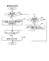
- control processing of the light irradiation device 100 includes the control method of the light irradiation device according to this embodiment. Control processing of the light irradiation device 100 is executed by the control unit 30 .
- control unit 30 controls the display unit 51 to display the operation reception screen 70 .
- control unit 30 selects one optical output port 12 to be calibrated.
- the order in which the optical output ports 12 are selected may be, for example, in ascending order of the port numbers, or may be specified by the operator.
- the operator connects the output end 22 of one light guide member 20 connected to the selected light output port 12 to the light input port 41 .
- the operator causes the light guide member 20 to emit the identification light 90 by inputting the first identification operation portion 73a or the second identification operation portion 73b of the operation reception screen 70 (see FIG. 7).
- the optical output port 12 to be calibrated is PORT1
- the operator inputs the first identification operation section 73a of PORT1.
- the identification light 90 (see FIG. 2) is emitted from the light guide member 20 connected to PORT1, so that the operator can easily distinguish the light guide member 20 connected to PORT1 from the other light guide members 20. can. Control regarding emission of the identification light 90 will be described later.
- the control section 30 executes calibration processing for the optical output port 12 to be calibrated.
- the calibration processing unit 31 b emits the therapeutic light 80 from the target light output port 12 and acquires the detection result from the light detection unit 40 .
- the calibration processing unit 31b compares the detection result of the light detection unit 40 and the set value of the emission intensity of the treatment light 80, and compares the detection result of the light detection unit 40 (the emission intensity of the treatment light 80 from the emission end 22). matches the intensity setting within tolerance.
- the control unit 30 determines whether or not the calibration processing has been completed normally based on the comparison between the detection result of the light detection unit 40 and the intensity setting value of the therapeutic light 80. . If the detection result of the light detection unit 40 does not match the intensity setting value within the allowable range even after the calibration processing is performed, the control unit 30 (calibration processing unit 31b) stops the subsequent processing and detects a predetermined error. Execute the process. If the detection result of the light detection unit 40 matches the intensity setting value within the allowable range, the control unit 30 (calibration processing unit 31b) determines that the calibration processing has been completed normally, and advances the processing to step 505. .
- the control unit 30 stops outputting the treatment light 80 from the light output port 12 for which the calibration processing has been completed, and controls the light source unit 10 to emit the identification light 90. That is, when the calibration processing for any of the optical output ports 12 is completed, the control unit 30 (calibration processing unit 31b) terminates the calibration processing by emitting the identification light 90 from the optical output port 12. inform the person. Emission of the identification light 90 is stopped after a predetermined time has elapsed.
- the control unit 30 determines whether or not an operation input instructing output of the therapeutic light 80 has been received.
- the control unit 30 receives an operation input instructing the output of the therapeutic light 80 through the second operation unit 53 (see FIG. 1).
- the operator Before inputting an operation, the operator arranges the plurality of light guide members 20 connected to the plurality of light output ports 12 at predetermined positions for irradiating the therapeutic light 80 to the treatment target region 101a of the patient 101. do.
- the emission end 22 of the light guide member 20 is inserted to a predetermined position inside the body of the patient 101 as described above.
- the operator performs an operation input to the second operation section 53 .
- the control unit 30 (light source control unit 31a) advances the process to step 508 . If the operation input is not accepted, the control unit 30 (light source control unit 31 a ) advances the process to step 509 .
- the control unit 30 controls the light source unit 10 to output therapeutic light 80 from each of the plurality of light output ports 12 .
- the treatment target region 101 a is irradiated with the treatment light 80 from the emission end 22 of the light guide member 20 connected to the light output port 12 .
- the control unit 30 (light source control unit 31a) outputs the therapeutic light 80 for the set irradiation time (see FIG. 7) based on the setting information 32b.
- the control unit 30 determines whether or not to end the treatment.
- a condition for ending one treatment is, for example, that the total irradiation time of the therapeutic light 80 reaches a set irradiation time.
- the control unit 30 determines to end the treatment when an input operation instructing the end of the treatment is received on the GUI displayed on the display unit 51, for example. In that case, the control process of the light irradiation device 100 is completed.
- control unit 30 determines in step 510 whether or not the setting information 32b has been changed.
- the operator operates the first operation unit 52 to display a setting screen (not shown) from the operation reception screen 70 on the display unit 51, and changes the setting information 32b for each optical output port 12 on the setting screen. perform an operation. Accordingly, it is possible to change the type of the light guide member 20 and change the setting information 32b such as the irradiation time and the total energy amount for each individual light output port 12 . In this case, the operator may need to confirm which light guide member 20 among the plurality of light guide members 20 is connected to the light output port 12 whose setting is to be changed.
- the operator can cause the light guide member 20 to emit the identification light 90 by inputting the first identification operation portion 73a or the second identification operation portion 73b.
- the identification light 90 is emitted from the light guide member 20 connected to the light output port 12 whose setting is to be changed. can be easily distinguished from other light guide members 20 .
- control unit 30 If the control unit 30 does not accept the change of the setting information 32b, the process returns to step S507.
- the control unit 30 causes the storage unit 32 to store the changed setting information 32b in step 511, and then returns the process to step S507.
- the irradiation condition of the therapeutic light 80 is changed, and the therapeutic light 80 is irradiated for the second time.
- the process may be returned to step 502 to perform the calibration process.
- control unit 30 determines that the treatments have ended in step 509, and ends the control processing of the light irradiation device 100.
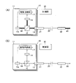
- Output control of identification light 90 will be described with reference to FIG. Output control of the identification light 90 is performed by the controller 30 . Output control of the identification light 90 is a process that is executed in parallel with the control process of the light irradiation device 100 shown in FIG.
- control section 30 determines whether or not an input operation to any of the first identification operation sections 73a has been received via the first operation section 52.
- the control unit 30 (light source control unit 31a) receives an input operation for any of the first identification operation units 73a, in step 522, the light output port 12 corresponding to the first identification operation unit 73a that has received the input operation.
- the light source unit 10 is controlled so as to output the identification light 90 from the .
- the control portion 30 (light source control portion 31a) causes the corresponding light output ports 12 to output the identification lights 90 at the same time.
- control unit 30 (light source control unit 31a) advances the process to step 523.
- the control section 30 determines whether or not an input operation to the second identification operation section 73 b has been received via the first operation section 52 .
- step 524 When the control unit 30 (light source control unit 31a) receives an input operation to the second identification operation unit 73b, in step 524, all the light output ports 12 output the identification lights 90 having different lighting and extinguishing patterns. Thus, the light source unit 10 is controlled. For example, the control unit 30 (light source control unit 31a) causes the light output ports 12 of PORT1 to PORT4 to output the identification light 90 having the pattern shown in FIG. If it is determined in step 523 that no input operation has been received with respect to the second identification operation section 73b, the process is terminated.
- the control unit 30 determines in step 525 whether the operation input to the first identification operation unit 73a or the second identification operation unit 73b has been released. determine whether or not In the case of the present embodiment in which the first operation unit 52 is a touch panel, it is determined whether or not the touch operation has been released. If the operation input is not canceled, the control section 30 (light source control section 31a) continues to output the identification light 90 .
- the control unit 30 (light source control unit 31a) stops outputting the identification light 90 in step 526. Therefore, in this embodiment, the identification light 90 is output only while the operation input to the first identification operation portion 73a or the second identification operation portion 73b continues.
- the control section 30 (light source control section 31a) ends the process.
- the control unit 30 (light source control unit 31a) always accepts an operation input to the first identification operation unit 73a or the second identification operation unit 73b by repeating the processing of steps 521 to 526 shown in FIG. Thereby, the operator can output the identification light 90 at a desired timing and for a desired period of time.
- the identification light 90 is output at the timing when the operator inputs the first identification operation section 73a or the second identification operation section 73b in step 502 or step 510 of FIG. Even at a timing other than step 502 or step 510, if the first identification operation portion 73a or the second identification operation portion 73b is input, the control portion 30 (light source control portion 31a) performs Control is performed to output the identification light 90 .
- the method for controlling the light irradiation device 100 of the present embodiment irradiates the treatment target region 101a of the subject (cancer patient 101) to whom the drug 102 containing a photosensitizer is administered with the therapeutic light 80.
- the light irradiation device 100 includes a plurality of light output ports 12, and configured to emit therapeutic light 80 and identification light 90 having a lower intensity than the therapeutic light 80 from each of the plurality of light output ports 12.
- a light source unit 10 an incident end 21 connected to one of the plurality of light output ports 12 of the light source unit 10, and a plurality of light guide members having an output end 22 for outputting the light incident from the incident end 21.
- the control unit 30 is connected to each of the plurality of light output ports 12 by emitting identification light 90 from each of the plurality of light output ports 12. It is configured to perform control to identifiably light the plurality of light guide members 20 .
- control method of the light irradiation device 100 of the present embodiment irradiates the treatment target region 101a of the subject (cancer patient 101) to whom the drug 102 containing the photosensitizer is administered, as described above, with the therapeutic light 80.
- the plurality of light guide members 20 connected to each of the plurality of light output ports 12 are emitted from each of the plurality of light output ports 12 by emitting the identification light 90 having a lower intensity than the therapeutic light 80.
- Identifiable lighting control is performed.
- the identification lights 90 are emitted from the plurality of optical output ports 12 separately one by one, or the identification lights 90 with different lighting patterns (flashing speeds, etc.) are emitted from the plurality of optical output ports 12 at the same time. This makes it possible to confirm from which light guide member 20 of the plurality of light guide members 20 the identification light 90 from each light output port 12 is emitted.
- the identification light 90 having a lower intensity than the treatment light 80 is emitted from the light guide member 20 , the identification light 90 can be confirmed without the goggles 60 .
- the identification light 90 can be confirmed without the goggles 60 .
- this makes it possible to shorten the preparation time required until the start of treatment.
- the light source unit 10 emits therapeutic light 80 of a first wavelength from each of the plurality of light output ports 12, and identification light of a second wavelength different from the first wavelength.
- light 90 can be emitted.
- the identification light 90 can be easily distinguished from the treatment light 80 by the identification light 90 having a second wavelength different from the treatment light 80 (that is, a color different from that of the treatment light 80).
- the second wavelength of the identification light 90 is a wavelength other than the first band of the goggles 60 that block light in the first band including the first wavelength of the therapeutic light 80, And the wavelength is within the range of visible light.
- the light source unit 10 includes a first light source 13 a that generates the therapeutic light 80 and a second light source 13 b that generates the identification light 90 . It is configured to be able to emit therapeutic light 80 and identification light 90 independently of each other. With this configuration, since the first light source 13a dedicated to the treatment light 80 and the second light source 13b dedicated to the identification light 90 are provided, treatment of the first wavelength can be performed without using a special wavelength tunable laser light source, for example. Light 80 and identification light 90 of the second wavelength can be emitted. Therefore, the light source unit 10 that emits the therapeutic light 80 and the identification light 90 can be easily configured.
- the light source section 10 is configured to be capable of individually switching between emitting and stopping the emission of the identification light 90 from each of the plurality of light output ports 12 .
- the identification light 90 can be selectively emitted from the plurality of optical output ports 12 one by one. Therefore, it is very easy to identify which light output port 12 each light guide member 20 is connected to.
- a plurality of first identification operation units are provided corresponding to the plurality of light output ports 12 and receive an operation input instructing emission of the identification light 90 for each of the light output ports 12. 73a.
- the control unit 30 controls the light source unit 10 to emit the identification light 90 from the light output port 12 corresponding to the first identification operation unit 73a that has received the operation input among the plurality of first identification operation units 73a.
- the light source unit 10 is configured to be capable of emitting the identification light 90 having different patterns of lighting and extinguishing in the unit time 110 from each of the plurality of light output ports 12 at the same time.
- the interconnection relationship between the plurality of light guide members 20 and the plurality of light output ports 12 is determined based on the difference in the pattern of the identification light 90 emitted from each of the plurality of light guide members 20. They can be specified collectively.
- one second identification operation is provided for the plurality of light output ports 12 and receives an operation input instructing emission of the identification light 90 from the plurality of light output ports 12. It further includes a portion 73b.
- the control unit 30 controls the light source unit 10 to emit identification lights 90 having different patterns from each of the plurality of light output ports 12 according to an operation input to the second identification operation unit 73b.
- the light irradiation device 100 of the present embodiment further includes a light detection section 40 that receives the output end 22 of one of the plurality of light guide members 20 and detects light output from the output end 22 .
- the control unit 30 is configured to perform calibration processing for adjusting the emission intensity of the therapeutic light 80 from each of the plurality of light output ports 12 based on the detection result of the light detection unit 40 .
- the control unit 30 determines whether or not the calibration process has been completed normally based on the comparison between the detection result of the light detection unit 40 and the setting value of the emission intensity of the therapeutic light 80. It is configured to perform control to cause the light source unit 10 to emit the identification light 90 when the calibration process is normally completed. With this configuration, the operator can easily recognize from the identification light 90 emitted from the light guide member 20 that the calibration process has been completed normally. In addition, since the light guide member 20 that has undergone the calibration process and the light guide member 20 that is about to be calibrated can be identified, the operator can select the light guide member 20 to be subjected to the calibration process from among the plurality of light guide members 20. can be deterred from being mixed up.
- the light source unit 10 includes the first light source 13a that emits the therapeutic light 80 and the second light source 13b that emits the identification light 90, but the present invention is not limited to this. No. In the present invention, the light source that generates the therapeutic light 80 and the light source that generates the identification light 90 may be the same light source.
- each light source unit 11 of the light source section 10 includes one first light source 13a.
- the light source unit 11 is not provided with a dedicated light source (second light source 13 b ) for generating the identification light 90 , and the first light source 13 a generates the therapeutic light 80 and the identification light 90 .
- the drive circuit unit 17 causes the first light source 13a to output the therapeutic light 80 of the first wavelength based on the signal from the control unit 30.
- the therapeutic light 80 is laser light with an intensity corresponding to Class 3 or Class 4.
- the drive circuit section 17 causes the first light source 13a to output the identification light 90 of the first wavelength.
- the identification light 90 is light of the first wavelength generated from the first light source 13 a and has a lower intensity than the treatment light 80 .
- the identification light 90 is laser light with an intensity corresponding to Class 1.
- the light source unit 10 identifies the light emitted from the same first light source 13a as the therapeutic light 80 by reducing the output intensity of light from the first light source 13a that generates the therapeutic light 80 to the level of class 1. It is used as the light 90.
- the difference in light intensity between the therapeutic light 80 and the identification light 90 is represented by arrows with different thicknesses.
- the therapeutic light 80 and the identification light 90 are lights of the same wavelength (first wavelength).
- the identification light 90 since the identification light 90 is light of a wavelength belonging to the first band blocked by the goggles 60 , the identification light 90 cannot be visually recognized while the operator is wearing the goggles 60 .
- the identification light 90 is a laser beam with an intensity corresponding to Class 1, the identification light 90 can be safely and reliably viewed when the worker removes the goggles 60 . Therefore, in this modified example, the operator removes the light shielding glasses 60 and checks the identification light 90 as necessary to determine which light output port 12 each light guide member 20 is connected to. can be easily identified.
- the intensity of the identification light 90 is sufficiently lower than that of the treatment light 80, so that the identification light 90 can be confirmed by removing the goggles 60. becomes.
- the identification light 90 can be generated using the first light source 13a for the treatment light 80 without providing a separate light source for the identification light 90, so that the identification light 90 is emitted separately from the treatment light 80. It is possible to simplify the device configuration for enabling.
- the light source unit 10 may include, as a light source, a wavelength tunable laser device capable of changing the wavelength of light to be output between a first wavelength and a second wavelength different from the first wavelength.
- a single light source can output the treatment light 80 of the first wavelength and the identification light of the second wavelength in a band in which the goggles 60 have a high transmittance.
- the light source unit 10 is configured to independently emit the therapeutic light 80 and the identification light 90 from the plurality of light output ports 12, but the present invention is not limited to this. .
- the light source section 10 may not be capable of independently emitting the therapeutic light 80 and the identification light 90 from the plurality of light output ports 12 .
- the light source unit 10 may be configured to simultaneously emit therapeutic light 80 from all the light output ports 12 and to emit identification light 90 from all the light output ports 12 at the same time.
- the light source section 10 does not have to include the plurality of light source units 11 . In other words, light may be distributed from one light source unit 11 to multiple light output ports 12 .
- the light source unit 10 is configured to be capable of individually switching between emitting and stopping the emission of the identification light 90 from each of the plurality of light output ports 12.
- the present invention is not limited to this. Not limited.
- the light source section 10 may simply emit the identification light 90 from all the light output ports 12 at the same time. Even when the identification light 90 is emitted from a plurality of optical output ports 12 at the same time, by varying the lighting and extinguishing patterns of the identification light 90 as described above, a plurality of conductors connected to the plurality of optical output ports 12 can be connected.
- the optical member 20 can be distinguished.
- the light source unit 10 may have a configuration in which the identification light 90 is emitted only from one optical output port 12 for which selection has been received, and the identification light 90 is not emitted from the plurality of optical output ports 12 at the same time.
- the identification light beams 90 when the identification light beams 90 are simultaneously emitted from the plurality of optical output ports 12, the identification light beams 90 having different lighting and extinguishing patterns in a unit time are emitted.
- the wavelength of the identification light 90 emitted from each of the plurality of optical output ports 12 may be made different. For example, by emitting the identification light 90 in such a manner that PORT1 is green, PORT2 is yellow, and PORT3 is blue, the difference in the identification light 90 can be recognized.
- the plurality of first identification operation sections 73a and second identification operation sections 73b are buttons (GUI) displayed on the display section 51, but the present invention is not limited to this.
- the plurality of first identification operation units 73a may be composed of mechanical switches.
- the second identification operation section 73b may be composed of a mechanical switch.
- the light detection section 40 is provided for receiving the output end 22 of any one of the plurality of light guide members 20 and detecting the light output from the output end 22.
- the light irradiation device 100 does not have to include the light detection section 40 .
- the calibration process may be performed using a photodetector provided separately from the light irradiation device 100 .
- the controller 30 controls the light source unit 10 to emit the identification light 90 when the calibration process ends normally, but the present invention is limited to this. can't In the present invention, it is not necessary to control the emission of the identification light 90 when the calibration process ends normally.
- the end of the calibration process may be notified by notification means other than emission of the identification light 90 .
- the notification means is, for example, voice output.
- the display unit 51 and the first operation unit 52 may each be configured separately from a display device and an input device such as a keyboard or mouse.
- a display unit 51 such as a liquid crystal display device
- a first operation unit 52 such as a keyboard and a mouse are installed in one housing in which the control unit 30 and the light source unit 10 are built. good.
- the display unit 51, the first operation unit 52, and the control unit 30 may constitute a single information terminal such as a tablet-type terminal.
- a light irradiation device for irradiating a treatment target site of a subject to which a drug containing a photosensitizer is administered with therapeutic light
- a light source unit including a plurality of light output ports configured to emit therapeutic light and identification light having a lower intensity than the therapeutic light from each of the plurality of light output ports; a plurality of light guide members each having an incident end connected to one of the plurality of light output ports of the light source section and an exit end for emitting light incident from the incident end;
- a control unit that controls the light source unit, The control unit is configured to emit identification light from each of the plurality of light output ports, thereby performing control for identifiably lighting the plurality of light guide members connected to each of the plurality of light output ports.
- (Item 2) Light irradiation according to item 1, wherein the light source unit is configured to be capable of emitting therapeutic light of a first wavelength and identification light of a second wavelength different from the first wavelength from each of the plurality of light output ports.
- the light source unit is configured to be capable of emitting therapeutic light of a first wavelength and identification light of a second wavelength different from the first wavelength from each of the plurality of light output ports.
- the light source unit includes a first light source that generates therapeutic light and a second light source that generates identification light, and is configured to be capable of independently emitting therapeutic light and identification light from a plurality of light output ports. , the light irradiation device according to item 2.
- (Item 6) further comprising a plurality of first identification operation units provided corresponding to the plurality of optical output ports and receiving an operation input instructing emission of identification light for each of the optical output ports; 6.
- (Item 8) further comprising a second identification operation unit provided for each of the plurality of optical output ports and receiving an operation input instructing emission of the identification light from the plurality of optical output ports;
- Item 8 The light irradiation device according to item 7, wherein the control unit controls the light source unit to emit identification light having different patterns from each of the plurality of light output ports according to an operation input to the second identification operation unit.
- the light source unit includes a first light source that generates therapeutic light of a first wavelength, Item 2.
- the light irradiation device according to item 1, wherein the identification light is light of the first wavelength generated from the first light source and has a lower intensity than the therapeutic light.
- (Item 10) further comprising a light detection unit that receives the output end of one of the plurality of light guide members and detects light output from the output end;
- the light irradiation device according to item 1, wherein the control unit is configured to perform a calibration process for adjusting the intensity of therapeutic light emitted from each of the plurality of light output ports based on the detection result of the light detection unit.
- the control unit determining whether or not the calibration process has been completed normally based on the comparison between the detection result of the light detection unit and the set value of the emission intensity of the therapeutic light; 11.
- the light irradiation device configured to perform control to cause the light source unit to emit the identification light when the calibration process ends normally.
- a control method for a light irradiation device for irradiating a treatment target site of a subject to which a drug containing a photosensitizer is administered comprising: The plurality of light guide members connected to each of the plurality of light guide members are emitted from each of the plurality of light output ports to which the plurality of light guide members are connected, by emitting identification light having an intensity lower than that of the therapeutic light. distinguishably lit; A method of controlling a light irradiation device, comprising: emitting therapeutic light from each of a plurality of light output ports.
- REFERENCE SIGNS LIST 10 light source unit 12 light output port 13a first light source 13b second light source 20 light guide member 21 entrance end 22 exit end 30 control unit 40 light detection unit 60 goggles 73a first identification operation unit 73b second identification operation unit 80 therapeutic light 90 identification light 100 light irradiation device 101 patient (subject) 101a Treatment target site 102 Drug 110 Unit time
Landscapes
- Health & Medical Sciences (AREA)
- Biomedical Technology (AREA)
- Engineering & Computer Science (AREA)
- Life Sciences & Earth Sciences (AREA)
- Nuclear Medicine, Radiotherapy & Molecular Imaging (AREA)
- Pathology (AREA)
- Radiology & Medical Imaging (AREA)
- Animal Behavior & Ethology (AREA)
- General Health & Medical Sciences (AREA)
- Public Health (AREA)
- Veterinary Medicine (AREA)
- Biophysics (AREA)
- Radiation-Therapy Devices (AREA)
Abstract
Priority Applications (4)
| Application Number | Priority Date | Filing Date | Title |
|---|---|---|---|
| PCT/JP2021/023495 WO2022269730A1 (fr) | 2021-06-22 | 2021-06-22 | Dispositif d'irradiation de lumière et procédé de commande pour dispositif d'irradiation de lumière |
| JP2023529255A JPWO2022269730A1 (fr) | 2021-06-22 | 2021-06-22 | |
| CN202180098503.5A CN117355358A (zh) | 2021-06-22 | 2021-06-22 | 光照射装置以及光照射装置的控制方法 |
| EP21947018.4A EP4360701A1 (fr) | 2021-06-22 | 2021-06-22 | Dispositif d'irradiation de lumière et procédé de commande pour dispositif d'irradiation de lumière |
Applications Claiming Priority (1)
| Application Number | Priority Date | Filing Date | Title |
|---|---|---|---|
| PCT/JP2021/023495 WO2022269730A1 (fr) | 2021-06-22 | 2021-06-22 | Dispositif d'irradiation de lumière et procédé de commande pour dispositif d'irradiation de lumière |
Publications (1)
| Publication Number | Publication Date |
|---|---|
| WO2022269730A1 true WO2022269730A1 (fr) | 2022-12-29 |
Family
ID=84545272
Family Applications (1)
| Application Number | Title | Priority Date | Filing Date |
|---|---|---|---|
| PCT/JP2021/023495 WO2022269730A1 (fr) | 2021-06-22 | 2021-06-22 | Dispositif d'irradiation de lumière et procédé de commande pour dispositif d'irradiation de lumière |
Country Status (4)
| Country | Link |
|---|---|
| EP (1) | EP4360701A1 (fr) |
| JP (1) | JPWO2022269730A1 (fr) |
| CN (1) | CN117355358A (fr) |
| WO (1) | WO2022269730A1 (fr) |
Citations (4)
| Publication number | Priority date | Publication date | Assignee | Title |
|---|---|---|---|---|
| JPS62172455U (fr) * | 1986-04-22 | 1987-11-02 | ||
| US5449354A (en) * | 1992-12-15 | 1995-09-12 | Laser Industries Ltd | Device for treating the interior of body cavities with laser energy |
| JP2002509777A (ja) * | 1998-03-30 | 2002-04-02 | ラザー・インダストリーズ・リミテツド | 組織ボリュームを治療するための装置 |
| WO2021038913A1 (fr) | 2019-08-27 | 2021-03-04 | 株式会社島津製作所 | Dispositif d'aide au traitement et procédé de génération d'image |
-
2021
- 2021-06-22 EP EP21947018.4A patent/EP4360701A1/fr active Pending
- 2021-06-22 CN CN202180098503.5A patent/CN117355358A/zh active Pending
- 2021-06-22 WO PCT/JP2021/023495 patent/WO2022269730A1/fr active Application Filing
- 2021-06-22 JP JP2023529255A patent/JPWO2022269730A1/ja active Pending
Patent Citations (4)
| Publication number | Priority date | Publication date | Assignee | Title |
|---|---|---|---|---|
| JPS62172455U (fr) * | 1986-04-22 | 1987-11-02 | ||
| US5449354A (en) * | 1992-12-15 | 1995-09-12 | Laser Industries Ltd | Device for treating the interior of body cavities with laser energy |
| JP2002509777A (ja) * | 1998-03-30 | 2002-04-02 | ラザー・インダストリーズ・リミテツド | 組織ボリュームを治療するための装置 |
| WO2021038913A1 (fr) | 2019-08-27 | 2021-03-04 | 株式会社島津製作所 | Dispositif d'aide au traitement et procédé de génération d'image |
Also Published As
| Publication number | Publication date |
|---|---|
| CN117355358A (zh) | 2024-01-05 |
| EP4360701A1 (fr) | 2024-05-01 |
| JPWO2022269730A1 (fr) | 2022-12-29 |
Similar Documents
| Publication | Publication Date | Title |
|---|---|---|
| KR101061004B1 (ko) | 광역학 치료 및 광 검출을 위한 장치 | |
| JP7361091B2 (ja) | ユーザウェアラブル蛍光対応可視化システム | |
| JP4532051B2 (ja) | 眼疾患を治療するための照射装置 | |
| CN107529978A (zh) | 光源装置、光源驱动方法与观察装置 | |
| JP2016120105A (ja) | 照明装置、照明方法及び観察装置 | |
| JP2004528943A (ja) | 後面投影視野テスタ | |
| JP7375821B2 (ja) | 治療支援装置および治療支援装置の作動方法 | |
| JP2016120104A (ja) | 照明装置、照明方法及び観察装置 | |
| WO2022269730A1 (fr) | Dispositif d'irradiation de lumière et procédé de commande pour dispositif d'irradiation de lumière | |
| CN102970918B (zh) | 用于对眼睛的视网膜成像的设备和方法 | |
| US20100081922A1 (en) | Diffuse optical tomography | |
| CA3139801A1 (fr) | Alignement de faisceaux laser a longueurs d'onde multiples avec les curs d'une fibre multi-cur | |
| JP7314941B2 (ja) | 眼科用レーザ治療装置 | |
| JP2023532409A (ja) | 診断用放射線を供給するシステムおよび方法 | |
| JP6687071B2 (ja) | 照明装置、照明方法及び観察装置 | |
| WO2019194519A1 (fr) | Appareil de traitement ophtalmique et son procédé de commande | |
| JP2004113322A (ja) | 眼科用治療装置 | |
| KR102588658B1 (ko) | 의료 장치의 광원을 캘리브레이션하기 위한 방법 및 장치 | |
| JP3990215B2 (ja) | 眼科用レーザ治療装置 | |
| JP2008017899A (ja) | 蛍光診断方法 | |
| JP2009226156A (ja) | 眼内照明用プローブ | |
| JPWO2018181976A1 (ja) | 眼科用レーザ治療装置 | |
| JP6687072B2 (ja) | 照明装置、照明方法及び観察装置 | |
| KR20240072129A (ko) | 광-활성화된 약물 전달을 위한 방법 및 시스템 | |
| JPH09540A (ja) | 手術用蛍光画像診断装置 |
Legal Events
| Date | Code | Title | Description |
|---|---|---|---|
| 121 | Ep: the epo has been informed by wipo that ep was designated in this application |
Ref document number: 21947018 Country of ref document: EP Kind code of ref document: A1 |
|
| WWE | Wipo information: entry into national phase |
Ref document number: 202180098503.5 Country of ref document: CN |
|
| WWE | Wipo information: entry into national phase |
Ref document number: 2023529255 Country of ref document: JP |
|
| WWE | Wipo information: entry into national phase |
Ref document number: 2021947018 Country of ref document: EP |
|
| NENP | Non-entry into the national phase |
Ref country code: DE |
|
| ENP | Entry into the national phase |
Ref document number: 2021947018 Country of ref document: EP Effective date: 20240122 |