WO2022264976A1 - 板状部材の製造方法及び板状部材 - Google Patents
板状部材の製造方法及び板状部材 Download PDFInfo
- Publication number
- WO2022264976A1 WO2022264976A1 PCT/JP2022/023684 JP2022023684W WO2022264976A1 WO 2022264976 A1 WO2022264976 A1 WO 2022264976A1 JP 2022023684 W JP2022023684 W JP 2022023684W WO 2022264976 A1 WO2022264976 A1 WO 2022264976A1
- Authority
- WO
- WIPO (PCT)
- Prior art keywords
- plate
- trajectory
- base material
- less
- pitch
- Prior art date
- Legal status (The legal status is an assumption and is not a legal conclusion. Google has not performed a legal analysis and makes no representation as to the accuracy of the status listed.)
- Ceased
Links
Images




Classifications
-
- C—CHEMISTRY; METALLURGY
- C03—GLASS; MINERAL OR SLAG WOOL
- C03B—MANUFACTURE, SHAPING, OR SUPPLEMENTARY PROCESSES
- C03B33/00—Severing cooled glass
- C03B33/02—Cutting or splitting sheet glass or ribbons; Apparatus or machines therefor
- C03B33/0222—Scoring using a focussed radiation beam, e.g. laser
-
- B—PERFORMING OPERATIONS; TRANSPORTING
- B23—MACHINE TOOLS; METAL-WORKING NOT OTHERWISE PROVIDED FOR
- B23K—SOLDERING OR UNSOLDERING; WELDING; CLADDING OR PLATING BY SOLDERING OR WELDING; CUTTING BY APPLYING HEAT LOCALLY, e.g. FLAME CUTTING; WORKING BY LASER BEAM
- B23K26/00—Working by laser beam, e.g. welding, cutting or boring
- B23K26/36—Removing material
- B23K26/38—Removing material by boring or cutting
-
- B—PERFORMING OPERATIONS; TRANSPORTING
- B23—MACHINE TOOLS; METAL-WORKING NOT OTHERWISE PROVIDED FOR
- B23K—SOLDERING OR UNSOLDERING; WELDING; CLADDING OR PLATING BY SOLDERING OR WELDING; CUTTING BY APPLYING HEAT LOCALLY, e.g. FLAME CUTTING; WORKING BY LASER BEAM
- B23K26/00—Working by laser beam, e.g. welding, cutting or boring
- B23K26/36—Removing material
- B23K26/38—Removing material by boring or cutting
- B23K26/382—Removing material by boring or cutting by boring
-
- B—PERFORMING OPERATIONS; TRANSPORTING
- B23—MACHINE TOOLS; METAL-WORKING NOT OTHERWISE PROVIDED FOR
- B23K—SOLDERING OR UNSOLDERING; WELDING; CLADDING OR PLATING BY SOLDERING OR WELDING; CUTTING BY APPLYING HEAT LOCALLY, e.g. FLAME CUTTING; WORKING BY LASER BEAM
- B23K26/00—Working by laser beam, e.g. welding, cutting or boring
- B23K26/36—Removing material
- B23K26/40—Removing material taking account of the properties of the material involved
-
- B—PERFORMING OPERATIONS; TRANSPORTING
- B23—MACHINE TOOLS; METAL-WORKING NOT OTHERWISE PROVIDED FOR
- B23K—SOLDERING OR UNSOLDERING; WELDING; CLADDING OR PLATING BY SOLDERING OR WELDING; CUTTING BY APPLYING HEAT LOCALLY, e.g. FLAME CUTTING; WORKING BY LASER BEAM
- B23K26/00—Working by laser beam, e.g. welding, cutting or boring
- B23K26/50—Working by transmitting the laser beam through or within the workpiece
- B23K26/53—Working by transmitting the laser beam through or within the workpiece for modifying or reforming the material inside the workpiece, e.g. for producing break initiation cracks
-
- C—CHEMISTRY; METALLURGY
- C03—GLASS; MINERAL OR SLAG WOOL
- C03B—MANUFACTURE, SHAPING, OR SUPPLEMENTARY PROCESSES
- C03B33/00—Severing cooled glass
- C03B33/02—Cutting or splitting sheet glass or ribbons; Apparatus or machines therefor
- C03B33/04—Cutting or splitting in curves, especially for making spectacle lenses
-
- C—CHEMISTRY; METALLURGY
- C03—GLASS; MINERAL OR SLAG WOOL
- C03B—MANUFACTURE, SHAPING, OR SUPPLEMENTARY PROCESSES
- C03B33/00—Severing cooled glass
- C03B33/02—Cutting or splitting sheet glass or ribbons; Apparatus or machines therefor
- C03B33/023—Cutting or splitting sheet glass or ribbons; Apparatus or machines therefor the sheet or ribbon being in a horizontal position
- C03B33/033—Apparatus for opening score lines in glass sheets
-
- C—CHEMISTRY; METALLURGY
- C03—GLASS; MINERAL OR SLAG WOOL
- C03C—CHEMICAL COMPOSITION OF GLASSES, GLAZES OR VITREOUS ENAMELS; SURFACE TREATMENT OF GLASS; SURFACE TREATMENT OF FIBRES OR FILAMENTS MADE FROM GLASS, MINERALS OR SLAGS; JOINING GLASS TO GLASS OR OTHER MATERIALS
- C03C21/00—Treatment of glass, not in the form of fibres or filaments, by diffusing ions or metals in the surface
- C03C21/001—Treatment of glass, not in the form of fibres or filaments, by diffusing ions or metals in the surface in liquid phase, e.g. molten salts, solutions
- C03C21/002—Treatment of glass, not in the form of fibres or filaments, by diffusing ions or metals in the surface in liquid phase, e.g. molten salts, solutions to perform ion-exchange between alkali ions
-
- C—CHEMISTRY; METALLURGY
- C03—GLASS; MINERAL OR SLAG WOOL
- C03C—CHEMICAL COMPOSITION OF GLASSES, GLAZES OR VITREOUS ENAMELS; SURFACE TREATMENT OF GLASS; SURFACE TREATMENT OF FIBRES OR FILAMENTS MADE FROM GLASS, MINERALS OR SLAGS; JOINING GLASS TO GLASS OR OTHER MATERIALS
- C03C23/00—Other surface treatment of glass not in the form of fibres or filaments
- C03C23/0005—Other surface treatment of glass not in the form of fibres or filaments by irradiation
- C03C23/0025—Other surface treatment of glass not in the form of fibres or filaments by irradiation by a laser beam
Definitions
- the present invention relates to a plate-shaped member manufacturing method and a plate-shaped member.
- Patent Document 1 describes that a flat glass member is irradiated with a laser beam to cut out a glass element from the glass member.
- the present invention has been made in view of the above problems, and an object of the present invention is to provide a plate-like member manufacturing method and a plate-like member that can suppress the occurrence of cracks.
- a method for manufacturing a plate-shaped member provides a laser beam that is pulse-oscillated along a first trajectory having a radius of curvature of 100 mm or more on the surface of a base material. forming a plurality of openings along the first trajectory on the surface of the base material by irradiating the base material with a radius of curvature of less than 100 mm that is continuous with the first trajectory on the surface of the base material. forming a plurality of openings along the second locus in the surface of the base material by irradiating the laser beam along the second locus; and openings along the first locus and the second locus. and cutting out a plate-shaped member from the base material by breaking the base material with the starting point of The irradiation pitch of the laser light is shorter than the irradiation pitch of the laser light on the first trajectory.
- the plate-shaped member according to the present disclosure has a first end face having a radius of curvature of 100 mm or more when viewed in the thickness direction, and a first end face connected to the first end face. and a second end surface having a radius of curvature of less than 100 mm when viewed from the thickness direction, wherein the first end surface has a linear damage extending in the thickness direction of the plate-shaped member. a plurality of linear damaged portions extending in the thickness direction of the plate-shaped member on the second end surface, and the pitch of the damaged portions on the first end surface is shorter than that of the damaged portions on the first end surface. A plurality of pitches are formed.
- FIG. 1 is a schematic cross-sectional view of a base material.
- FIG. 2 is a schematic diagram illustrating irradiation of laser light along the first trajectory.
- FIG. 3 is a schematic diagram illustrating irradiation of laser light along the second trajectory.
- FIG. 4 is a schematic diagram showing an example in which openings are formed over the entire trajectory.
- FIG. 5 is a schematic diagram of a plate member.
- FIG. 6 is a flow chart for explaining the production flow of the plate member according to this embodiment.
- FIG. 7 is a graph showing an example of stress distribution in the thickness direction of the plate member.
- FIG. 8 is a schematic diagram showing an in-vehicle display according to this embodiment.
- FIG. 9 is a schematic diagram for explaining the trajectory of cutting out the base material in the example.
- FIG. 10 is a schematic diagram for explaining a crack measuring method.
- the base material 10 is irradiated with the laser beam L to form the opening H in the base material 10, and the base material 10 is broken starting from the opening H, so that the plate-like member 100 is formed from the base material 10. cut out.
- the surface of a base material is irradiated with a pulsed laser beam along a first trajectory having a radius of curvature of 100 mm or more. forming a plurality of openings along the first trajectory in the surface of the material; forming a plurality of openings along the second trajectory in the surface of the base material by irradiating light; and breaking the base material starting from the openings along the first trajectory and the second trajectory.
- the irradiation pitch of the laser light on the first trajectory is 9 ⁇ m or less
- the irradiation pitch of the laser light on the second trajectory is: It is characterized by being shorter than the irradiation pitch of the laser light on the first locus.
- FIG. 1 is a schematic cross-sectional view of a base material.
- the base material 10 is a transparent plate-like member.
- the plate shape here is not limited to a flat plate shape, and may refer to a main surface having a width longer than the thickness, and the transparent here may refer to transmitting visible light.
- one main surface of the base material 10 is defined as a surface 10A
- the main surface on the opposite side of the surface 10A is defined as a surface 10B
- the thickness direction of the base material 10 that is, the direction connecting the surfaces 10B and 10A is the Z direction.
- the base material 10 has a rectangular flat plate shape when viewed from the Z direction, but the shape of the base material 10 may be arbitrary.
- the base material 10 is not limited to being rectangular when viewed from the Z direction, and may be polygonal, circular, elliptical, or the like.
- the base material 10 has a flat plate shape, but is not limited to this, and may have a shape in which a flat plate is curved. That is, the base material 10 may have a curved surface shape in which the surfaces 10A and 10B are convex in the Z direction.
- the radius of curvature of the surfaces 10A and 10B of the base material 10 is preferably 10000 mm or less, more preferably 5000 mm or less. , 3000 mm or less.
- the radius of curvature of the surfaces 10A and 10B of the base material 10 is preferably 10 mm or more, more preferably 50 mm or more. 100 mm or more is more preferable, and 200 mm or more is particularly preferable.
- the thickness D of the base material 10 is preferably 0.2 mm or more, more preferably 0.8 mm or more, and even more preferably 1 mm or more.
- the thickness D of the base material 10 is preferably 5 mm or less, more preferably 3 mm or less, and even more preferably 2 mm or less.
- the thickness D of the base material 10 refers to the length in the Z direction from the surface 10A to the surface 10B. By setting the thickness D within this range, the rigidity can be appropriately improved.
- the base material 10 is preferably glass, more preferably alkali glass containing an alkali component.
- the base material 10 is the same material as the plate member 100 described later. However, when the plate-like member 100 is chemically strengthened as described later, the composition of the base material 10 corresponds to the composition of the central portion of the plate-like member 100 in the plate thickness direction. Specifically, if an element released by substitution during chemical strengthening is defined as a pre-substitution element, and an element incorporated by substitution during chemical strengthening is defined as a replacement element, the plate member 100 is It can be said that the chemically strengthened surface layer has a composition containing the pre-substitution element instead of the substitution element.
- a method for manufacturing the plate member 100 from the base material 10 will be described.
- a surface 10A of a base material 10 is irradiated with a laser beam L from an irradiation device A to form an opening H in the surface 10A of the base material 10 . That is, the opening H is a hole formed by the laser beam L.
- FIG. 1 In this manufacturing method, a surface 10A of a base material 10 is irradiated with a laser beam L from an irradiation device A to form an opening H in the surface 10A of the base material 10 . That is, the opening H is a hole formed by the laser beam L.
- the opening H is a linear damaged portion that penetrates from the surface 10A to the surface 10B, but may be a linear damaged portion that does not penetrate to the surface 10B.
- the linear damaged portion may include a modified portion formed by the laser beam L.
- the modified portion has a change in density or refractive index due to structural changes in the glass or due to melting and resolidification.
- the linear damaged portion may include voids in addition to the modified portion, and cracks may exist in each void.
- the irradiation device A irradiates a pulsed laser beam L (pulse laser).
- the spot diameter DL of the laser beam L may be arbitrary, but is preferably, for example, 1 ⁇ m or more and 30 ⁇ m or less, more preferably 2 ⁇ m or more and 20 ⁇ m or less, and even more preferably 3 ⁇ m or more and 10 ⁇ m or less.
- the spot diameter DL refers to the diameter of the laser beam L at the most converged position (diameter at the focal position).
- the wavelength band of the laser light L may be arbitrary, but may be, for example, 350 nm or more and 1100 nm or less.
- the irradiation device A may irradiate the laser light L with an arbitrary output, but may output the laser light L with an output value of 10 W or more and 150 W or less, for example, and the output value of the laser light L can be changed. It's okay.
- the irradiation device A has a light source section A1, a condenser lens A2, and a scanning mechanism A3.
- the light source unit A1 is a light source that generates laser light L.
- the condenser lens A2 is provided on the traveling direction side of the laser beam L with respect to the light source unit A1, and the laser beam L from the light source unit A1 is incident thereon.
- the condensing lens A2 collects the incident laser light L and emits it toward the surface 10A.
- the scanning mechanism A3 is a mechanism for scanning (sweeping) the laser light L. As shown in FIG.
- the scanning mechanism A3 scans (moves) the irradiation position, which is the position where the surface 10A is irradiated with the laser light L, in a direction parallel to the surface 10A.
- the scanning mechanism A3 may be any mechanism as long as it can scan the laser light L, and may be, for example, a galvanomirror.
- the configuration of the irradiation device A is not limited to the above description, and may be any configuration that can irradiate the laser light L while scanning the irradiation position in a direction parallel to the surface 10A.
- the position of the laser head irradiated with the laser light L such as the light source unit A1 and the condenser lens A2 is fixed, and the base material 10 irradiated with the laser light L is moved to scan the irradiation position. It's okay. That is, by moving the relative position between the spot position of the laser beam L and the base material 10, the scanning position may be scanned.
- a plurality of openings H are formed at predetermined intervals along the scanning direction (moving direction) of the irradiation position by irradiating the laser beam L while scanning the irradiation position. That is, in this manufacturing method, a plurality of openings H are formed in the front surface 10A of the base material 10 along the scanning trajectory of the irradiation position of the laser beam L and arranged at predetermined intervals.
- FIG. 2 is a schematic diagram illustrating irradiation of laser light along the first trajectory.
- the trajectory T for scanning the irradiation position of the laser beam L on the surface 10A of the base material 10 includes the first trajectory T1 and the second trajectory T2. set.
- the first trajectory T1 has a radius of curvature R1 of 100 mm or more, preferably 1000 mm or more, and more preferably 2500 mm or more when viewed from the Z direction.
- the first trajectory T1 has a large radius of curvature, the upper limit of which is not particularly limited, and may be linear, for example.
- the second trajectory T2 is a trajectory that is continuous with the first trajectory T1 (connected to the first trajectory T1).
- the second trajectory T2 has a radius of curvature R2 of less than 100 mm, preferably 2 mm or more, and more preferably 3 mm or more when viewed in the Z direction.
- the curvature radius R2 is preferably 10 mm or less, more preferably 5 mm or less.
- the second trajectory T2 has a smaller radius of curvature than the first trajectory T1 and has a curved shape.
- the trajectory T includes four first trajectories T1 corresponding to the four sides of the rectangle and four second trajectories T2 provided between the pair of first trajectories T1. Yes, but not limited to.
- the trajectory T may have any shape including the first trajectory T1 and the second trajectory T2.
- the surface 10A of the base material 10 is irradiated with the laser beam L along the first trajectory T1. That is, the irradiation position of the laser light L is scanned (moved) along the first trajectory T1, and the pulsed laser light L is irradiated. Thereby, a plurality of openings H1 are formed in the front surface 10A of the base material 10 along the first locus T1.
- the diameter D1 of the opening H1 is preferably 0.2 ⁇ m or more and 20 ⁇ m or less, more preferably 0.5 ⁇ m or more and 10 ⁇ m or less, and further preferably 1 ⁇ m or more and 5 ⁇ m or less.
- the distance between the centers of the openings H1 adjacent along the first locus T1 be the irradiation pitch P1 of the laser light on the first locus.
- the openings H1 are formed so that the irradiation pitch P1 is 9 ⁇ m or less.
- the irradiation pitch P1 is preferably 6 ⁇ m or more, and more preferably more than 7 ⁇ m.
- the irradiation pitch P1 is preferably 8 ⁇ m or less.
- the irradiation pitch P1 is preferably 400% or more and 600% or less, more preferably 450% or more and 550% or less, with respect to the diameter D1 of the opening H1.
- the irradiation pitch P1 is preferably 120% or more, more preferably 140% or more, of the spot diameter DL of the laser beam L.
- the irradiation pitch P1 is preferably 180% or less, more preferably 160% or less, of the spot diameter DL of the laser light L.
- FIG. 3 is a schematic diagram illustrating irradiation of laser light along the second trajectory.
- the surface 10A of the base material 10 is irradiated with the laser beam L along the second trajectory T2. That is, the irradiation position of the laser light L is scanned (moved) along the second trajectory T2, and the pulsed laser light L is irradiated.
- a plurality of openings H2 are formed in the surface 10A of the base material 10 along the second trajectory T2.
- the diameter D2 of the opening H2 is preferably 0.2 ⁇ m or more and 20 ⁇ m or less, more preferably 0.5 ⁇ m or more and 10 ⁇ m or less, and further preferably 1 ⁇ m or more and 5 ⁇ m or less.
- the distance between the centers of the openings H2 adjacent along the second locus T2 be the irradiation pitch P2 of the laser light on the second locus.
- the openings H2 are formed such that the irradiation pitch P2 is shorter than the irradiation pitch P1 of the openings H1.
- the irradiation pitch P2 is preferably 7 ⁇ m or less, more preferably 6 ⁇ m or less.
- the irradiation pitch P2 is preferably 450% or less, more preferably 350% or more and 400% or less, with respect to the diameter D2 of the opening H2.
- the irradiation pitch P2 is preferably 140% or less, more preferably 120% or less, of the spot diameter DL of the laser beam L. Further, it is preferable that the irradiation pitch P2 is 100% or more of the spot diameter DL of the laser light L.
- the irradiation pitch P2 is preferably 2000% or less, more preferably 40% or more and 200% or less, and 60% or more of the curvature radius R2 of the second locus T2. It is more preferably 100% or less.
- FIG. 4 is a schematic diagram showing an example in which openings are formed over the entire trajectory.
- the opening H is formed over the entire section of the locus T, as shown in FIG. That is, in the section of the first trajectory T1 of the trajectory T, the openings H1 are formed with the irradiation pitch P1, and in the section of the second trajectory T2, the openings H2 are formed with the irradiation pitch P2.
- FIG. 4 shows only partial openings H1 and H2 in the first trajectory T1 and the second trajectory T2. Openings H1 and H2 are formed throughout.
- the opening H1 is first formed along the first trajectory T1, and then the opening H2 is formed along the second trajectory T2 continuing from the first trajectory T1.
- An opening H1 or an opening H2 is formed along the trajectory in order.
- the order of forming the openings H1 and H2 is not limited to that. may be formed. That is, in the example of FIG. 4, a second trajectory T2, a first trajectory T1 continuing to the second trajectory T2, a second trajectory T2 continuing to the first trajectory T1, and a first trajectory T1 continuing to the second trajectory T2 , the opening H1 or the opening H2 may be formed along the locus.
- the openings H1 on the respective first loci T1 may be formed on the respective second loci T2, or after forming the openings H2 on the respective second loci T2, on the respective second loci T2.
- the opening H1 may be formed on the first locus T1, or the opening H1 on the first locus T1 and the opening H2 on the second locus T2 may be formed at the same time.
- FIG. 5 is a schematic diagram of a plate member. After the opening H1 is formed on the first locus T1 and the opening H2 is formed on the second locus T2, in the present manufacturing method, the base material 10 is broken with the openings H1 and H2 as starting points, thereby forming a plate-like shape from the base material 10. The member 100 is separated (cut out).
- the opening H1 is formed along the first locus T1 and the opening H2 is formed along the second locus T2, by breaking the base material 10 with the openings H1 and H2 as starting points, the base material 10
- the plate member 100 is cut out along the first trajectory T1 and the second trajectory T2, as shown in FIG.
- the plate member 100 has a first end surface 101 that is a fracture surface along the first trajectory T1 and a second end surface 102 that is a fracture surface along the second trajectory T2.
- a damaged portion HA1 corresponding to the opening H1 remains on 101, and a damaged portion HA2 corresponding to the opening H2 remains on the second end face 102.
- damaged portions HA1 and HA2 on the first end surface 101 and the second end surface 102 are shown. Damaged portions HA1 and HA2 are formed at the ends.
- stress may be generated on the surface 10A along the trajectory T, thereby breaking the base material 10 with the openings H1 and H2 as starting points.
- stress is generated along the trajectory T on the surface 10A, and the base material 10 is fractured starting from the openings H1 and H2.
- the method of breaking the base material 10 starting from the openings H1 and H2 is not limited to irradiation with a CO 2 laser.
- a stress may be generated on the surface 10A to break the base material 10 starting from the openings H1 and H2.
- the mechanical means here refers to physically generating a bending load.
- the bending load may be generated by a machine, or may be manually generated by an operator.
- the plate-like member 100 cut out from the base material 10 may be chemically strengthened to form a compressive stress layer on the surface of the plate-like member 100 .
- the chemical strengthening treatment may be performed by any method.
- the plate-like member 100 is immersed in molten salt containing an alkali metal.
- a typical method includes immersing the plate member 100 in a KNO 3 molten salt, subjecting it to ion exchange treatment, and then cooling it to around room temperature.
- the treatment conditions such as the temperature of the KNO 3 molten salt and the immersion time may be set so that the surface compressive stress and the thickness of the compressive stress layer have desired values.
- the chemical strengthening method is not limited to using a potassium salt such as KNO3 molten salt , and may be any method. For example, it may be chemically strengthened with a sodium salt.
- the chemical strengthening treatment is preferably performed after cutting out the plate-shaped member 100, but is not limited thereto.
- the plate-shaped member 100 may be cut out from the material.
- FIG. 6 is a flow chart for explaining the production flow of the plate member according to this embodiment.
- the base material 10 is prepared, the surface 10A of the base material 10 is irradiated with the laser beam L along the first trajectory T1, and the laser beam L is irradiated along the first trajectory T1.
- a plurality of openings H1 arranged side by side are formed (step S10).
- the surface 10A of the base material 10 is irradiated with the laser light L along the second trajectory T2 that continues from the first trajectory T1, thereby forming a plurality of openings H2 that are aligned along the second trajectory T2 (step S12). ).
- the opening H1 is formed along the first locus T1. That is, in this embodiment, the openings H1 and H2 are formed along the trajectory T in the order of the first trajectory T1, the second trajectory T2, the first trajectory T1, . . . .
- the execution order of steps S10 and S12 may be arbitrary.
- openings H1 and H2 may be formed in the order of second trajectory T2, first trajectory T1, second trajectory T2, . . . .
- the opening H1 of the first locus T1 and the opening H2 of the second locus T2 may be separately formed instead of forming along the continuous locus T along the road.
- the base material 10 is broken starting from the openings H1 and H2 of the first trajectory T1 and the second trajectory T2 to cut out the plate member 100 (step S14).
- the plate-like member 100 is manufactured.
- the plate-like member 100 cut out from the base material 10 may be chemically strengthened.
- Plate member 100 Characteristics of the plate member 100 will be described below.
- the plate-like member 100 described below is manufactured by the manufacturing method described above, but any manufacturing method may be used as long as it has the characteristics described below.
- the plate member 100 includes a surface 100A that is one main surface and a surface 100B that is the other main surface. That is, the area cut out as the plate-like member 100 from the surface 10A of the base material 10 becomes the surface 100A of the plate-like member 100, and the area cut out as the plate-like member 100 from the surface 10B of the base material 10 becomes the surface 100A of the plate-like member 100. , become the surface 100B of the plate member 100 .
- the plate member 100 has a first end surface 101 that is an end surface formed by breaking along the first locus T1, and a second end surface 102 that is an end surface formed by breaking along the second locus T2. including.
- the thickness of the plate member 100 may be the same as the thickness D of the base material 10.
- the plate-like member 100 is in the shape of a flat plate, but it is not limited to this, and may be in the shape of a curved flat plate. That is, the plate-like member 100 may have curved surfaces 100A and 100B convex in the Z direction.
- the radius of curvature of the surfaces 100A and 100B of the plate-like member 100 is preferably 10000 mm or less, more preferably 5000 mm or less. More preferably, it is 3000 mm or less.
- the radius of curvature of the surfaces 100A and 100B of the plate-like member 100 is preferably 10 mm or more, more preferably 50 mm or more. It is preferably 100 mm or more, more preferably 200 mm or more.
- the first end surface 101 of the plate-like member 100 is a cross section formed by breaking the base material 10 along the first trajectory T1. Therefore, at least part of the opening H1 formed in the base material 10 remains on the first end surface 101 as the damaged portion HA1.
- the damaged portion HA1 is a part of the opening H1 formed by irradiation with the laser beam L, and can be said to be a linear damaged portion that is an irradiation mark of the laser beam L (laser mark). That is, the first end face 101 is formed with a linear damaged portion HA1 extending in the Z direction (axial direction). In the first end surface 101, a plurality of damaged portions HA1 are formed along the circumferential direction when the Z direction is the axial direction (that is, along the first locus T1).
- the radius of curvature of the line (corresponding to the first trajectory T1) connecting the centers of the damaged portions HA1 when viewed from the Z direction is defined as the radius of curvature RA1 of the first end surface 101 viewed from the Z direction.
- a curvature radius RA1 of the first end surface 101 corresponds to the curvature radius R1 of the first locus T1, and is 100 mm or more, preferably 1000 mm or more, and more preferably 2500 mm or more.
- the upper limit of the curvature radius RA1 of the first end face 101 is not particularly limited, and may be, for example, a straight line.
- the center of the damaged portion HA1 refers to the end portion HA1a on one side of the damaged portion HA1 in the circumferential direction of the first end surface 101 (that is, the direction along the first locus T1), and the other end portion HA1a of the damaged portion HA1.
- the edge on the side is the edge HA1b
- it refers to the midpoint between the edge HA1a and the edge HA1b on the surface 100A, in other words, it can be said to be the midpoint of the width ⁇ H1 described later.
- the width ⁇ H1 of the damaged portion HA1 when viewed from the Z direction is preferably 20 ⁇ m or less, more preferably 10 ⁇ m or less, and even more preferably 5 ⁇ m or less.
- the distance from the end HA1a to the end HA1b on the surface 100A is the width ⁇ H1 of the damaged portion HA1.
- the pitch PA1 corresponds to the irradiation pitch P1 and is 9 ⁇ m or less. Also, in the present embodiment, the pitch PA1 is preferably 6 ⁇ m or more, more preferably over 7 ⁇ m. The pitch PA1 is preferably 8 ⁇ m or less.
- the pitch PA1 is preferably 600% or less, more preferably 400% or more and 600% or less, and even more preferably 450% or more and 550% or less of the width ⁇ H1 of the damaged portion HA1.
- the pitch PA1 may refer to the average value of the pitches PA1 of 10 pairs of adjacent damaged portions HA1 arbitrarily selected in each trajectory.
- the second end surface 102 is an end surface continuous with the first end surface 101 (connected to the first end surface 101).
- the second end face 102 is a cross section formed by breaking the base material 10 along the second trajectory T2. Therefore, at least part of the opening H2 formed in the base material 10 remains on the second end surface 102 as the damaged portion HA2.
- the damaged portion HA2 is a part of the opening H2 formed by the irradiation of the laser beam L, and can be said to be a linear damaged portion that is an irradiation trace of the laser beam L (laser trace). That is, the second end surface 102 is formed with a linear damaged portion HA2 extending in the Z direction (axial direction). In the second end surface 102, a plurality of damaged portions HA2 are formed along the circumferential direction when the Z direction is the axial direction (that is, along the second locus T2).
- the radius of curvature of the line (corresponding to the second trajectory T2) connecting the centers of the damaged portions HA2 when viewed from the Z direction is defined as the radius of curvature RA2 of the second end surface 102 viewed from the Z direction.
- the radius of curvature RA2 of the second end face 102 corresponds to the radius of curvature R2 of the second trajectory T2 and is less than 100 mm, preferably 10 mm or less, more preferably 5 mm or less.
- the radius of curvature RA2 of the second end surface 102 is preferably 2 mm or more, more preferably 3 mm or more.
- the second end face 102 has a radius of curvature smaller than that of the first end face 101 and has an R shape.
- the center of the damaged portion HA2 is defined as the end portion HA2a on one side of the damaged portion HA2 in the circumferential direction of the second end face 102 (that is, the direction along the second trajectory T2), and the other end portion of the damaged portion HA2.
- the edge on the side is the edge HA2b
- the width ⁇ H2 of the damaged portion HA2 when viewed in the Z direction is half the diameter D2 of the opening H2 (that is, the radius of the opening H2), and is preferably 20 ⁇ m or less, more preferably 10 ⁇ m or less, and 5 ⁇ m. More preferably: The distance from the end HA2a to the end HA2b on the surface 100A is the width ⁇ H2 of the damaged portion HA2.
- the pitch PA2 corresponds to the irradiation pitch P2 and is shorter than the pitch PA1 of the damaged portion HA1.
- the pitch PA2 is preferably 7 ⁇ m or less, more preferably 6 ⁇ m or less.
- the pitch PA2 is preferably 5 ⁇ m or more.
- the pitch PA2 is preferably 450% or less, more preferably 350% or more and 400% or less, of the width ⁇ H2 of the damaged portion HA2.
- the pitch PA2 is preferably 2000% or less, more preferably 40% or more and 200% or less, and preferably 60% or more and 100% or less of the curvature radius RA2 of the second end surface 102. More preferred.
- the plate-like member 100 with the pitch PA2 within this range is one in which the formation of cracks in the second end surface 102 (cracks other than the damaged portion HA2) is suppressed.
- the pitch PA2 may refer to the average value of the pitches PA2 of 10 pairs of adjacent damaged portions HA2 that are arbitrarily selected in each trajectory.
- the plate member 100 has the damaged portion HA1 formed on the first end surface 101 and the damaged portion HA2 formed on the second end surface 102. As shown in FIG. However, the damaged portions HA1 and HA2 may be removed by polishing the first end surface 101 and the second end surface 102 .
- the plate-shaped member 100 has no damaged portions (cracks) other than the damaged portion HA1 on the first end face 101 .
- a groove having a distance of 100 ⁇ m or more from a line (corresponding to the first trajectory T1) connecting the centers of the damaged portions HA1 when viewed in the Z direction to the bottom surface of the groove is formed in the plate of the present embodiment. It may be judged as a damaged portion (crack) other than the damaged portion HA1 in the shaped member.
- the plate member 100 preferably has no damaged portions (cracks) other than the damaged portion HA2 on the second end surface 102 .
- the groove having a distance of 100 ⁇ m or more from the line (corresponding to the second trajectory T2) connecting the centers of the damaged portions HA2 to the bottom surface of the groove is formed into the plate shape of the present embodiment. It may be judged as a damaged portion (crack) other than the damaged portion HA2 in the member.
- the plate member 100 is a transparent plate member. Although the plate member 100 may be made of any material, it is preferably glass. The plate member 100 may be amorphous glass or crystallized glass containing crystals on the surface or inside.
- the plate member 100 for example, alkali-free glass, soda lime glass, soda lime silicate glass, aluminosilicate glass, borosilicate glass, lithium aluminosilicate glass, borosilicate glass, etc. can be used.
- the material of the plate member 100 is preferably alkali glass in order to perform chemical strengthening appropriately.
- aluminosilicate glass or lithium aluminosilicate glass is preferable, because even if the thickness is thin, a large stress is likely to be applied by tempering treatment, and a high-strength glass can be obtained even if the thickness is thin.
- Glass for chemical strengthening based on aluminosilicate glass for example, "Dragontrail (registered trademark)" manufactured by AGC is also preferably used.
- the plate member 100 contains 50% to 80% SiO 2 , 1% to 20% Al 2 O 3 , and 6% to 20% Na 2 O in terms of mol % based on oxides. good.
- the plate member 100 contains 50 to 80% SiO 2 , 0.1 to 25% Al 2 O 3 , 3 to 30% Li 2 O+Na 2 O+K 2 O, and MgO in terms of mol % based on oxides. 0-25%, CaO 0-25% and ZrO 2 0-5%.
- the plate member 100 contains 50% to 80% SiO 2 , 1% to 20% Al 2 O 3 , 6% to 20% Na 2 O, and K 2 O in terms of mol % based on oxides. It may contain 0% to 11%, 0% to 15% MgO, 0% to 6% CaO, and 0% to 5% ZrO 2 .
- the numerical range represented using “-” means the range including the numerical values described before and after "-” as the lower limit and the upper limit.
- 50% to 80% here means 50% or more and 80% or less when the mol % of the total amount of the plate member 100 is 100%, and the same applies to other numerical ranges. be.
- Li 2 O+Na 2 O+K 2 O indicates the total content of Li 2 O, Na 2 O and K 2 O, and the same applies to other cases where "+" is used.
- the following glass composition can be mentioned.
- containing 0% to 25% MgO means that although MgO is not essential, up to 25% may be contained.
- the glass of (i) is included in soda lime silicate glass, the glasses of (ii) and (iii) are included in aluminosilicate glass, and the glasses of (iv) and (v) are included in lithium aluminosilicate glass.
- the composition expressed in mole %, is 68%-80% SiO2 , 4 %-10% Al2O3 , 5%-15% Na2O , 0 %-1% K2O; , a glass containing 0% to 5% Li 2 O, 4% to 15% MgO and 0% to 1% ZrO 2
- the composition expressed in mole %, is 67%-75% SiO2 , 0%-4% Al2O3 , 7%-15% Na2O , 1% -9 % K2O; , containing 0% to 5% Li 2 O, 6% to 14% MgO and 0% to 1.5% ZrO 2 , the total content of SiO 2 and Al 2 O 3 being 71% to 75% , Na 2 O and K 2 O in a total content of 12% to 20%, and the content of CaO, if any, is less than 1%.
- the composition expressed in mole %, is 56% to 73% SiO2 , 10% to 24% Al2O3 , 0 % to 6 % B2O3 , and 0 % to P2O5; 6% Li 2 O, 2%-7% Na 2 O, 3%-11% Na 2 O, 0%-5% K 2 O, 0%-8% MgO, 0%-2% CaO, SrO 0%-5% BaO 0%-5% ZnO 0%-5% TiO 2 0%-2% ZrO 2 0%-4%
- the plate-shaped member 100 includes a compressive stress layer when the chemical strengthening treatment is performed.
- the compressive stress layer is formed on the entire surface of plate member 100, that is, on surface 100A, surface 100B, first end face 101 and second end face 102 here.
- the plate-like member 100 is not limited to forming a compressive stress layer on all of the surface 100A, the surface 100B, the first end surface 101, and the second end surface 102.
- a compressive stress layer may be formed on at least one of the second end face 102 (preferably at least the surface 100A).
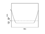
- FIG. 7 is a graph showing an example of the stress distribution in the thickness direction of the plate member.
- a compressive stress layer is a layer in which a compressive stress acts within the plate member 100 .
- a compressive stress S acts on the surface of the plate-like member 100, and the compressive stress decreases toward the center in the thickness direction of the plate-like member.
- the compressive stress layer is the portion of the entire plate-shaped member 100 that extends from the surface until the stress becomes zero.
- tensile stress acts on the plate member 100 in layers deeper than the depth at which the stress is zero.
- the compressive stress acting on the surface of the plate-like member 100 that is, the surface of the compressive stress layer, will be referred to as surface compressive stress CS.
- the plate member 100 preferably has a surface compressive stress CS of 500 MPa or more and 1200 MPa or less, more preferably 650 MPa or more, and even more preferably 750 MPa or more.
- a decrease in impact resistance can be appropriately suppressed.
- the method of measuring the surface compressive stress CS is arbitrary, but for example, it may be measured by measuring the strain in the plate member 100 using photoelastic analysis.
- the surface compressive stress CS may be measured using a surface stress meter FSM-6000LE manufactured by Orihara Seisakusho.
- the depth DOL of the compressive stress layer of the plate member 100 is preferably 10 ⁇ m or more and 100 ⁇ m or less, more preferably 15 ⁇ m or more, still more preferably 25 ⁇ m or more, and particularly preferably 30 ⁇ m or more.
- the depth DOL refers to the thickness of the compressive stress layer in the plate member 100 . That is, the depth DOL refers to the distance in the thickness direction from the surface of the plate member 100 on which the surface compressive stress CS is acting to the depth at which the compressive stress value becomes zero.
- the plate member 100 having the depth DOL within this range can appropriately suppress a decrease in impact resistance.
- the depth DOL may be measured by any method, for example, the depth DOL may be measured by measuring strain in the plate member 100 using a photoelastic analysis method. In this embodiment, for example, the depth DOL may be measured using a surface stress meter FSM-6000LE manufactured by Orihara Seisakusho.
- FIG. 8 is a schematic diagram showing an in-vehicle display according to this embodiment. As shown in FIG. 8, the plate-like member 100 according to the present embodiment is provided on the vehicle-mounted display 2 and used as a cover material for the surface of the vehicle-mounted display.
- the in-vehicle display 2 is a display device provided in the vehicle, and is provided on the front side of the steering shaft 1 inside the vehicle, for example.
- the in-vehicle display 2 displays, for example, a car navigation screen, various meters such as a speedometer, a start button, and the like.
- the configuration of FIG. 8 is an example, and the vehicle-mounted display 2 to which the plate member 100 is applied may have any configuration.
- the plate member 100 is not limited to being used as a cover material for the surface of an in-vehicle display, and may be used for any purpose.
- the manufacturing method according to the present embodiment irradiates the surface 10A of the base material 10 with the pulse-oscillated laser light L along the first trajectory T1 having a radius of curvature of 100 mm or more.
- the irradiation pitch P1 of the laser beams L on the first trajectory T1 is 9 ⁇ m or less, and the irradiation pitch P2 of the laser beams L on the second trajectory T2 is shorter than the irradiation pitch P1.
- the inventors have found that the stress is concentrated on the curved second locus T2 at the time of fracture, so that the risk of crack generation on the second end surface 102 corresponding to the second locus T2 is higher. rice field.
- the irradiation pitch P2 of the second trajectory T2 shorter than the irradiation pitch P1 of the first trajectory T1
- the occurrence of cracks on the second end surface 102 can be suppressed.
- the base material 10 is broken along the first trajectory T1 and the second trajectory T2
- the generation of cracks can be suppressed by devising the irradiation pitches P1 and P2.
- the base material 10 is preferably glass, more preferably alkali glass.
- the plate-like member 100 made of glass can be appropriately manufactured, and by using alkali glass as the base material 10, the plate-like member 100 can be appropriately chemically strengthened.
- the irradiation pitch P1 of the laser light L on the first trajectory T1 is preferably 120% or more and 180% or less of the spot diameter DL of the laser light L
- the irradiation pitch P2 of the laser light L on the second trajectory T2 is , the spot diameter DL of the laser beam L is preferably 140% or less.
- the irradiation pitch P2 of the laser light L on the second trajectory T2 is preferably 7 ⁇ m or less. By setting the irradiation pitch P2 within this range, the occurrence of cracks on the second end surface 102 can be more preferably suppressed.
- the radius of curvature of the first trajectory T1 is preferably 1000 mm or more, and the radius of curvature of the second trajectory T2 is preferably 2 mm or more and 10 mm or less. According to this embodiment, it is possible to appropriately suppress the occurrence of cracks when the base material 10 is broken along such a trajectory.
- the base material 10 preferably has a curved surface 10A with a radius of curvature of 10000 mm or less.
- Such a curved base material 10 may have a high risk of cracking when broken, but by setting the irradiation pitches P1 and P2 as in the present embodiment, cracks can be prevented from occurring. It can be suppressed appropriately.
- the plate-shaped member 100 is preferably used as a cover material for a vehicle-mounted display device. According to the present embodiment, it is possible to appropriately suppress the occurrence of cracks in the plate-like member 100 provided in the vehicle-mounted display device.
- the plate member 100 includes a first end surface 101 having a radius of curvature of 100 mm or more when viewed in the Z direction (thickness direction), and a Z direction (thickness direction) connected to the first end surface 101. and a second end face 102 having a radius of curvature of less than 100 mm when viewed from above.
- a plurality of linear damaged portions HA1 extending in the thickness direction (Z direction) of the plate-shaped member 100 are formed on the first end surface 101 at a pitch PA1 of 9 ⁇ m or less.
- a plurality of linear damaged portions HA2 extending in the thickness direction of the shaped member 100 are formed at a pitch PA2 shorter than the pitch PA1 of the damaged portions HA1.
- the pitch PA1 of the damaged portion HA1 of the first end surface 101 is 9 ⁇ m or less
- the pitch PA2 of the damaged portion HA2 of the second end surface 102 is shorter than the pitch PA1, so that crack generation is suppressed.
- the damaged portions HA1 and HA2 are preferably laser marks.
- the pitch PA1 of the laser marks on the first facet 101 is 9 ⁇ m or less
- the pitch PA2 of the laser marks on the second facet 102 is shorter than the pitch PA1, so cracks are suppressed.
- the plate member 100 is preferably made of glass and preferably has a compressive stress layer on its surface. Since the plate member 100 is made of glass, it can be used for various purposes, and having a compressive stress layer on the surface can improve strength.
- the pitch PA1 of the damaged portion HA1 of the first end surface 101 is preferably 600% or less of the width ⁇ H1 of the damaged portion HA1 of the first end surface 101, and the pitch PA2 of the damaged portion HA2 of the second end surface 102 is:
- the width ⁇ H2 of the damaged portion HA2 of the second end surface 102 is preferably 450% or less.
- the pitch PA2 of the damaged portion HA2 of the second end surface 102 is preferably 7 ⁇ m or less. By setting the pitch PA2 within this range, the occurrence of cracks on the second end surface 102 can be more preferably suppressed.
- the radius of curvature of the first end face 101 when viewed in the Z direction (thickness direction) is preferably 1000 mm or more, and the radius of curvature of the second end face 102 when viewed in the Z direction (thickness direction) is preferably 2 mm or more. It is preferably 10 mm or less. According to the present embodiment, it is possible to appropriately suppress the occurrence of cracks when manufacturing the plate member 100 having such a shape.
- the plate member 100 preferably has a curved surface 100A with a radius of curvature of 10000 mm or less. Such a curved plate-like member 100 may have a high risk of cracking during manufacturing. can be suppressed.
- the plate-shaped member 100 is preferably used as a cover material for a vehicle-mounted display device. According to the present embodiment, it is possible to appropriately suppress the occurrence of cracks in the plate-like member 100 provided in the vehicle-mounted display device.
- a plurality of openings along the first locus are formed on the surface of the base material by irradiating the surface of the base material with pulse-oscillated laser light along the first locus having a radius of curvature of 100 mm or more. forming; By irradiating the surface of the base material with the laser beam along a second locus having a curvature radius of less than 100 mm, which is continuous with the first locus, the surface of the base material is irradiated with the laser beam along the second locus.
- a method for manufacturing a plate member [2] The method for manufacturing a plate member according to [1], wherein the base material is glass. [3] The method for manufacturing a plate member according to [2], wherein the base material is alkali glass.
- the irradiation pitch of the laser light on the first trajectory is 120% or more and 180% or less of the spot diameter of the laser light
- the irradiation pitch of the laser light on the second trajectory is the laser light
- [6] The method for manufacturing a plate-shaped member according to any one of [1] to [5], wherein the irradiation pitch of the laser light on the second trajectory is 5 ⁇ m or more.
- [7] The plate member according to any one of [1] to [6], wherein the radius of curvature of the first locus is 1000 mm or more, and the radius of curvature of the second locus is 2 mm or more and 10 mm or less.
- Production method [8] The method for manufacturing a plate member according to any one of [1] to [6], wherein the base material has a curved surface with a radius of curvature of 10000 mm or less.
- a plate-shaped member having A plurality of linear damaged portions extending in the thickness direction of the plate member are formed on the first end face at a pitch of 9 ⁇ m or less, A plurality of linear damaged portions extending in the thickness direction of the plate member are formed on the second end face at a pitch shorter than the pitch of the damaged portions on the first end face. Plate-shaped member.
- the pitch of the damaged portion of the first end face is 600% or less of the width of the damaged portion of the first end face, and the pitch of the damaged portion of the second end face is equal to or less than the damage of the second end face.
- the radius of curvature of the first end face when viewed in the thickness direction is 1000 mm or more, and the radius of curvature of the second end face when viewed in the thickness direction is 2 mm or more and 10 mm or less, [9] to [ 13], the plate member according to any one of the above.
- the plate-shaped member according to any one of [9] to [15] which is used as a cover material for a vehicle-mounted display device.
- Examples 1 to 4 and 7 are examples, and examples 5 and 6 are comparative examples.
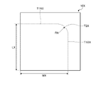
- FIG. 9 is a schematic diagram for explaining the trajectory of cutting out the base material in the example.
- a base material having a length of 50 mm, a width of 50 mm, and a thickness of 1.3 mm was prepared.
- Dragontrail (registered trademark) manufactured by AGC was used as the base material.
- the plate member cut out from the base material has a vertical length LX of 30 mm, a horizontal width WX of 30 mm, and a curvature radius RX of the R portion of 3 mm.
- a first trajectory T1AX extending in the horizontal direction
- a first trajectory T1BX extending in the vertical direction
- a second trajectory T1AX connecting the first trajectory T1AX and the second trajectory T1BX.
- a trajectory T2X was set. That is, the first trajectories T1AX and T1BX are linear, and the second trajectory T2X is curved with a curvature radius RX of 3 mm.
- Example 1 a plurality of openings were formed along the trajectory by irradiating pulsed laser light along the trajectory set in this manner.
- the pulsed laser light device and irradiation conditions were as follows. Apparatus: StarPico3 manufactured by Rofin Irradiation conditions: ⁇ Wavelength: 1064 nm ⁇ Pulse width: ⁇ 10 ps ⁇ Output: 35W ⁇ Frequency: 75 kHz ⁇ Number of bursts: 4 ⁇ Spot diameter: 5 ⁇ m ⁇ Irradiation pitch in the first trajectory: 8 ⁇ m ⁇ Irradiation pitch in the second trajectory: 5 ⁇ m
- a plate-like member was cut out by irradiating a CO 2 laser to the base material in which the openings were formed by irradiating the laser beam under the above conditions, breaking the base material along the trajectory.
- the CO 2 laser irradiation apparatus and irradiation conditions were as follows. Apparatus: SR15i manufactured by Rofin ⁇ Pulse width: 20 ⁇ s ⁇ Pulse period: 200 ⁇ s ⁇ Spot diameter: 3 mm ⁇ Scanning speed: 60mm/s
- Example 2 a plate member was obtained in the same manner as in Example 1, except that the irradiation pitch of the pulsed laser light in the second locus was set to 7 ⁇ m.
- Example 3 a plate-like member was obtained in the same manner as in Example 1, except that the radius of curvature RX of the second trajectory T2X was set to 2 mm.
- Example 4 a plate-like member was obtained in the same manner as in Example 1, except that the irradiation pitch of the pulsed laser light in the first trajectories T1AX and T1BX was set to 9 ⁇ m.
- Example 5 a plate-like member was obtained in the same manner as in Example 1, except that the irradiation pitch of the pulsed laser light in the second trajectory was set to 8 ⁇ m.
- Example 6 a plate-like member was obtained in the same manner as in Example 1, except that the irradiation pitch of the pulsed laser light in the first trajectories T1AX and T1BX was set to 10 ⁇ m.
- Example 7 Dragontrail (registered trademark) manufactured by AGC and having a thickness of 2.0 mm was used as the base material.
- the base material had a curved shape with a curvature radius of 1800 mm with the short side direction as the bending axis.
- a plate member was cut out from the base material along the first trajectories T1AX and T1BX which were linear, and the second trajectory T2X which was a curved trajectory with a curvature radius RX of 10 mm.
- the irradiation pitch of the pulsed laser light on the first locus was set to 7 ⁇ m
- the irradiation pitch of the pulsed laser light on the second locus was set to 5 ⁇ m.
- Other devices and irradiation conditions for the pulsed laser light, and devices and irradiation conditions for the CO 2 laser were the same as in Example 1.
- Table 1 shows the evaluation results in each example.
- the method for cutting out the plate member in each example was evaluated based on whether or not it could be cut out with a CO 2 laser. As shown in Table 1, when a plate-like member could be cut out with a CO 2 laser, it was described as CO 2 , and when a plate-like member could not be cut out with a CO 2 laser and was cut out by hand, , hand.
- FIG. 10 is a schematic diagram for explaining a crack measuring method. As shown in FIG. 10, for the plate member 100X of each example, the crack height C of the end surface (fractured surface) when viewed from the main surface was measured.
- the distance between the line LX connecting the centers of the damaged portions HAX corresponding to the openings formed in the base material and the bottom surface of the crack was measured as the height C.
- the distance from the line LX to the tip of the protruding portion was taken as the height C of the crack.
- the maximum height C in the first trajectories T1AX, T1BX and the second trajectory T2X was calculated as the maximum crack.
- the maximum crack is less than 100 ⁇ m and the plate-shaped member can be cut out with the CO 2 laser, it is evaluated as A, and the maximum crack is less than 100 ⁇ m and the plate-shaped member is cut out with the CO 2 laser.
- Evaluation B was given when the plate-like member could be cut out by hand, but evaluation NG was given when the maximum crack was 100 ⁇ m or more, or when the plate-like member could not be cut out by either the CO 2 laser or by hand. Evaluations A and B were regarded as acceptable, and evaluation NG was regarded as unacceptable.
- Example 7 As shown in Table 1, in Examples 1 to 4, which are examples, the irradiation pitch of the first trajectory is 9 ⁇ m or less, and the irradiation pitch of the second trajectory is shorter than the irradiation pitch of the first trajectory. , the evaluation is A or B, and it can be seen that the occurrence of cracks can be suppressed. In addition, in Example 7, which is an embodiment, even when the base material has a curved surface shape with a radius of curvature of 10000 mm or less, it can be seen that the occurrence of cracks can be suppressed under the above conditions.
- Example 5 which is a comparative example
- the irradiation pitch of the second trajectory is not shorter than the irradiation pitch of the first trajectory, and it can be seen that the occurrence of cracks cannot be suppressed.
- Example 6 which is a comparative example, the irradiation pitch of the first trajectory is more than 9 ⁇ m, and it can be seen that the occurrence of cracks cannot be suppressed.
Landscapes
- Engineering & Computer Science (AREA)
- Physics & Mathematics (AREA)
- Optics & Photonics (AREA)
- Chemical & Material Sciences (AREA)
- Plasma & Fusion (AREA)
- Mechanical Engineering (AREA)
- Materials Engineering (AREA)
- Organic Chemistry (AREA)
- Chemical Kinetics & Catalysis (AREA)
- General Chemical & Material Sciences (AREA)
- Oil, Petroleum & Natural Gas (AREA)
- Laser Beam Processing (AREA)
Priority Applications (3)
| Application Number | Priority Date | Filing Date | Title |
|---|---|---|---|
| EP22824965.2A EP4357307A4 (en) | 2021-06-16 | 2022-06-13 | METHOD FOR PRODUCING A PLATE-SHAPED MEMBER AND PLATE-SHAPED MEMBER |
| JP2023529868A JPWO2022264976A1 (https=) | 2021-06-16 | 2022-06-13 | |
| CN202280042558.9A CN117480133A (zh) | 2021-06-16 | 2022-06-13 | 板状构件的制造方法和板状构件 |
Applications Claiming Priority (2)
| Application Number | Priority Date | Filing Date | Title |
|---|---|---|---|
| JP2021100357 | 2021-06-16 | ||
| JP2021-100357 | 2021-06-16 |
Publications (1)
| Publication Number | Publication Date |
|---|---|
| WO2022264976A1 true WO2022264976A1 (ja) | 2022-12-22 |
Family
ID=84526497
Family Applications (1)
| Application Number | Title | Priority Date | Filing Date |
|---|---|---|---|
| PCT/JP2022/023684 Ceased WO2022264976A1 (ja) | 2021-06-16 | 2022-06-13 | 板状部材の製造方法及び板状部材 |
Country Status (5)
| Country | Link |
|---|---|
| EP (1) | EP4357307A4 (https=) |
| JP (1) | JPWO2022264976A1 (https=) |
| CN (1) | CN117480133A (https=) |
| TW (1) | TW202311179A (https=) |
| WO (1) | WO2022264976A1 (https=) |
Citations (6)
| Publication number | Priority date | Publication date | Assignee | Title |
|---|---|---|---|---|
| JP2012521889A (ja) * | 2009-03-27 | 2012-09-20 | エレクトロ サイエンティフィック インダストリーズ インコーポレーテッド | 脆性材料の加工のための改善された方法 |
| WO2014010490A1 (ja) * | 2012-07-09 | 2014-01-16 | 旭硝子株式会社 | 強化ガラス板の切断方法 |
| JP2017528322A (ja) * | 2014-07-09 | 2017-09-28 | ハイ キュー レーザー ゲゼルシャフト ミット ベシュレンクテル ハフツングHigh Q Laser GmbH | 非円形レーザビームを用いる材料の処理 |
| JP2019511989A (ja) | 2016-02-17 | 2019-05-09 | ショット アクチエンゲゼルシャフトSchott AG | ガラスエレメントの端面加工のための方法、およびその方法により加工されたガラスエレメント |
| JP2021020833A (ja) * | 2019-07-30 | 2021-02-18 | 三星ダイヤモンド工業株式会社 | 基板の加工方法並びに加工装置 |
| JP2021100357A (ja) | 2019-12-23 | 2021-07-01 | 株式会社デンソー | 電力変換装置 |
Family Cites Families (9)
| Publication number | Priority date | Publication date | Assignee | Title |
|---|---|---|---|---|
| TWI476063B (zh) * | 2011-10-04 | 2015-03-11 | Ind Tech Res Inst | 雷射切割方法與裝置 |
| EP2781296B1 (de) * | 2013-03-21 | 2020-10-21 | Corning Laser Technologies GmbH | Vorrichtung und verfahren zum ausschneiden von konturen aus flächigen substraten mittels laser |
| CN107406293A (zh) * | 2015-01-12 | 2017-11-28 | 康宁股份有限公司 | 使用多光子吸收方法来对经热回火的基板进行激光切割 |
| GB201505042D0 (en) * | 2015-03-25 | 2015-05-06 | Nat Univ Ireland | Methods and apparatus for cutting a substrate |
| US10668561B2 (en) * | 2016-11-15 | 2020-06-02 | Coherent, Inc. | Laser apparatus for cutting brittle material |
| CN110678422A (zh) * | 2017-04-25 | 2020-01-10 | 康宁公司 | 3d激光穿孔热下垂工艺 |
| KR102580292B1 (ko) * | 2018-05-29 | 2023-09-19 | 삼성디스플레이 주식회사 | 표시 장치, 그 제조 방법 및 표시 장치 제조를 위한 레이저 가공 장치 |
| DE102019129036A1 (de) * | 2019-10-28 | 2021-04-29 | Schott Ag | Verfahren zur Herstellung von Glasscheiben und verfahrensgemäß hergestellte Glasscheibe sowie deren Verwendung |
| KR102241518B1 (ko) * | 2020-11-17 | 2021-04-19 | 주식회사 아이티아이 | 세라믹 절단방법 및 장치 |
-
2022
- 2022-06-13 WO PCT/JP2022/023684 patent/WO2022264976A1/ja not_active Ceased
- 2022-06-13 JP JP2023529868A patent/JPWO2022264976A1/ja active Pending
- 2022-06-13 CN CN202280042558.9A patent/CN117480133A/zh active Pending
- 2022-06-13 EP EP22824965.2A patent/EP4357307A4/en active Pending
- 2022-06-16 TW TW111122386A patent/TW202311179A/zh unknown
Patent Citations (6)
| Publication number | Priority date | Publication date | Assignee | Title |
|---|---|---|---|---|
| JP2012521889A (ja) * | 2009-03-27 | 2012-09-20 | エレクトロ サイエンティフィック インダストリーズ インコーポレーテッド | 脆性材料の加工のための改善された方法 |
| WO2014010490A1 (ja) * | 2012-07-09 | 2014-01-16 | 旭硝子株式会社 | 強化ガラス板の切断方法 |
| JP2017528322A (ja) * | 2014-07-09 | 2017-09-28 | ハイ キュー レーザー ゲゼルシャフト ミット ベシュレンクテル ハフツングHigh Q Laser GmbH | 非円形レーザビームを用いる材料の処理 |
| JP2019511989A (ja) | 2016-02-17 | 2019-05-09 | ショット アクチエンゲゼルシャフトSchott AG | ガラスエレメントの端面加工のための方法、およびその方法により加工されたガラスエレメント |
| JP2021020833A (ja) * | 2019-07-30 | 2021-02-18 | 三星ダイヤモンド工業株式会社 | 基板の加工方法並びに加工装置 |
| JP2021100357A (ja) | 2019-12-23 | 2021-07-01 | 株式会社デンソー | 電力変換装置 |
Non-Patent Citations (1)
| Title |
|---|
| See also references of EP4357307A4 |
Also Published As
| Publication number | Publication date |
|---|---|
| EP4357307A4 (en) | 2025-07-09 |
| TW202311179A (zh) | 2023-03-16 |
| JPWO2022264976A1 (https=) | 2022-12-22 |
| CN117480133A (zh) | 2024-01-30 |
| EP4357307A1 (en) | 2024-04-24 |
Similar Documents
| Publication | Publication Date | Title |
|---|---|---|
| US12590024B2 (en) | Method for separating substrates | |
| JP5790826B2 (ja) | 強化板ガラス | |
| KR102006509B1 (ko) | 화학 강화 유리판 및 그 제조 방법 | |
| CN104736489B (zh) | 使用激光切割玻璃的方法 | |
| KR102819853B1 (ko) | 관통 구멍을 갖는 유리 기판 | |
| TW201702201A (zh) | 雷射加工用玻璃、及使用其之附孔玻璃之製造方法 | |
| TW202212282A (zh) | 用於穿玻璃通孔應用之高氧化硼低氧化鋁無鹼玻璃 | |
| JPWO2019193918A1 (ja) | レーザービームを用いた加工のための光学装置、レーザービームを用いた加工方法、及びガラス物品の製造方法 | |
| JP2005289683A (ja) | レーザー照射で異質相が形成されてなる強化ガラス | |
| WO2022264976A1 (ja) | 板状部材の製造方法及び板状部材 | |
| EP4516749A1 (en) | Method for producing glass article, and glass article | |
| KR20180041066A (ko) | 화학 강화용 유리 | |
| KR20210127179A (ko) | 부분적으로 텍스처링된 유리 물품의 제조 방법 | |
| WO2023100495A1 (ja) | ガラス管 | |
| JP2003286048A (ja) | 強化ガラスの製造方法 | |
| TW201802054A (zh) | 包含光提取特徵之玻璃物件及其製造方法 | |
| TW202438460A (zh) | 玻璃物品之製造方法 | |
| JP2021088474A (ja) | ガラス物品の製造方法、及びガラス物品 | |
| TW202608839A (zh) | 玻璃板及玻璃板之製造方法 | |
| JP2024175490A (ja) | ガラス物品の製造方法及びガラス物品 | |
| JP4363637B2 (ja) | レーザー照射で異質相が形成された強化ガラス及び当該強化法に適したガラス組成物 | |
| JP2024167060A (ja) | 化学強化ガラス及び化学強化ガラスの製造方法 | |
| EA042227B1 (ru) | Способ изготовления частично текстурированного стеклянного изделия | |
| KR20240163061A (ko) | 유리 | |
| TW202334047A (zh) | 可熔合形成的高斷裂韌性玻璃 |
Legal Events
| Date | Code | Title | Description |
|---|---|---|---|
| 121 | Ep: the epo has been informed by wipo that ep was designated in this application |
Ref document number: 22824965 Country of ref document: EP Kind code of ref document: A1 |
|
| WWE | Wipo information: entry into national phase |
Ref document number: 2023529868 Country of ref document: JP |
|
| WWE | Wipo information: entry into national phase |
Ref document number: 202280042558.9 Country of ref document: CN |
|
| WWE | Wipo information: entry into national phase |
Ref document number: 2022824965 Country of ref document: EP |
|
| NENP | Non-entry into the national phase |
Ref country code: DE |
|
| ENP | Entry into the national phase |
Ref document number: 2022824965 Country of ref document: EP Effective date: 20240116 |