WO2022264851A1 - 半導体装置 - Google Patents
半導体装置 Download PDFInfo
- Publication number
- WO2022264851A1 WO2022264851A1 PCT/JP2022/022797 JP2022022797W WO2022264851A1 WO 2022264851 A1 WO2022264851 A1 WO 2022264851A1 JP 2022022797 W JP2022022797 W JP 2022022797W WO 2022264851 A1 WO2022264851 A1 WO 2022264851A1
- Authority
- WO
- WIPO (PCT)
- Prior art keywords
- semiconductor elements
- semiconductor device
- electrode
- semiconductor
- electrically connected
- Prior art date
- Legal status (The legal status is an assumption and is not a legal conclusion. Google has not performed a legal analysis and makes no representation as to the accuracy of the status listed.)
- Ceased
Links
Images









Classifications
-
- H—ELECTRICITY
- H03—ELECTRONIC CIRCUITRY
- H03K—PULSE TECHNIQUE
- H03K17/00—Electronic switching or gating, i.e. not by contact-making and –breaking
- H03K17/12—Modifications for increasing the maximum permissible switched current
- H03K17/122—Modifications for increasing the maximum permissible switched current in field-effect transistor switches
-
- H—ELECTRICITY
- H03—ELECTRONIC CIRCUITRY
- H03K—PULSE TECHNIQUE
- H03K17/00—Electronic switching or gating, i.e. not by contact-making and –breaking
- H03K17/51—Electronic switching or gating, i.e. not by contact-making and –breaking characterised by the components used
- H03K17/56—Electronic switching or gating, i.e. not by contact-making and –breaking characterised by the components used by the use, as active elements, of semiconductor devices
- H03K17/687—Electronic switching or gating, i.e. not by contact-making and –breaking characterised by the components used by the use, as active elements, of semiconductor devices the devices being field-effect transistors
- H03K17/6871—Electronic switching or gating, i.e. not by contact-making and –breaking characterised by the components used by the use, as active elements, of semiconductor devices the devices being field-effect transistors the output circuit comprising more than one controlled field-effect transistor
-
- H—ELECTRICITY
- H02—GENERATION; CONVERSION OR DISTRIBUTION OF ELECTRIC POWER
- H02M—APPARATUS FOR CONVERSION BETWEEN AC AND AC, BETWEEN AC AND DC, OR BETWEEN DC AND DC, AND FOR USE WITH MAINS OR SIMILAR POWER SUPPLY SYSTEMS; CONVERSION OF DC OR AC INPUT POWER INTO SURGE OUTPUT POWER; CONTROL OR REGULATION THEREOF
- H02M1/00—Details of apparatus for conversion
- H02M1/08—Circuits specially adapted for the generation of control voltages for semiconductor devices incorporated in static converters
-
- H—ELECTRICITY
- H03—ELECTRONIC CIRCUITRY
- H03K—PULSE TECHNIQUE
- H03K17/00—Electronic switching or gating, i.e. not by contact-making and –breaking
- H03K17/16—Modifications for eliminating interference voltages or currents
- H03K17/161—Modifications for eliminating interference voltages or currents in field-effect transistor switches
- H03K17/162—Modifications for eliminating interference voltages or currents in field-effect transistor switches without feedback from the output circuit to the control circuit
-
- H—ELECTRICITY
- H10—SEMICONDUCTOR DEVICES; ELECTRIC SOLID-STATE DEVICES NOT OTHERWISE PROVIDED FOR
- H10W—GENERIC PACKAGES, INTERCONNECTIONS, CONNECTORS OR OTHER CONSTRUCTIONAL DETAILS OF DEVICES COVERED BY CLASS H10
- H10W44/00—Electrical arrangements for controlling or matching impedance
- H10W44/501—Inductive arrangements
-
- H—ELECTRICITY
- H10—SEMICONDUCTOR DEVICES; ELECTRIC SOLID-STATE DEVICES NOT OTHERWISE PROVIDED FOR
- H10W—GENERIC PACKAGES, INTERCONNECTIONS, CONNECTORS OR OTHER CONSTRUCTIONAL DETAILS OF DEVICES COVERED BY CLASS H10
- H10W72/00—Interconnections or connectors in packages
- H10W72/50—Bond wires
-
- H—ELECTRICITY
- H10—SEMICONDUCTOR DEVICES; ELECTRIC SOLID-STATE DEVICES NOT OTHERWISE PROVIDED FOR
- H10W—GENERIC PACKAGES, INTERCONNECTIONS, CONNECTORS OR OTHER CONSTRUCTIONAL DETAILS OF DEVICES COVERED BY CLASS H10
- H10W90/00—Package configurations
-
- H—ELECTRICITY
- H03—ELECTRONIC CIRCUITRY
- H03K—PULSE TECHNIQUE
- H03K2217/00—Indexing scheme related to electronic switching or gating, i.e. not by contact-making or -breaking covered by H03K17/00
- H03K2217/009—Resonant driver circuits
-
- H—ELECTRICITY
- H10—SEMICONDUCTOR DEVICES; ELECTRIC SOLID-STATE DEVICES NOT OTHERWISE PROVIDED FOR
- H10W—GENERIC PACKAGES, INTERCONNECTIONS, CONNECTORS OR OTHER CONSTRUCTIONAL DETAILS OF DEVICES COVERED BY CLASS H10
- H10W90/00—Package configurations
- H10W90/701—Package configurations characterised by the relative positions of pads or connectors relative to package parts
- H10W90/751—Package configurations characterised by the relative positions of pads or connectors relative to package parts of bond wires
- H10W90/754—Package configurations characterised by the relative positions of pads or connectors relative to package parts of bond wires between a chip and a stacked insulating package substrate, interposer or RDL
Definitions
- the present disclosure relates to semiconductor devices.
- a power module described in Patent Document 1 includes a plurality of first semiconductor elements, a plurality of first connection wirings, wiring layers, and signal terminals.
- the plurality of first semiconductor elements are, for example, MOSFETs. Each first semiconductor element is turned on/off according to a drive signal input to the gate terminal. The plurality of first semiconductor elements are connected in parallel.
- the plurality of first connection wirings are wires, for example, and connect the gate terminals of the plurality of first semiconductor elements and the wiring layer.
- a signal terminal is connected to the wiring layer.
- the signal terminal is connected to the gate terminal of each first semiconductor element via the wiring layer and each first connection wiring.
- the signal terminal supplies a drive signal for driving each first semiconductor element to the gate terminal of each first semiconductor element.
- the present disclosure has been conceived in view of the above circumstances, and an object thereof is to provide a semiconductor device capable of suppressing a resonance phenomenon that occurs when a plurality of semiconductor elements are operated in parallel.
- a semiconductor device of the present disclosure each has a first electrode, a second electrode, and a third electrode, and a plurality of first electrodes whose switching operation is controlled according to a first drive signal input to the third electrode.
- a semiconductor element a first control terminal for inputting the first drive signal; electrically connected to the first control terminal and electrically interposed between the third electrodes of the plurality of first semiconductor elements; a first conductive member; and a plurality of first circuit components connected to the first conductive member for increasing impedance in a first frequency band, wherein the plurality of first semiconductor elements are electrically connected to each other.
- the first frequency band includes a resonance frequency of a resonance circuit formed including parasitic inductance of the first conducting member
- the third electrodes of the plurality of first semiconductor elements are: They are electrically connected to each other through at least one of the plurality of first circuit components.
- the semiconductor device of the present disclosure it is possible to suppress the resonance phenomenon.
- FIG. 1 is a perspective view showing a semiconductor device according to a first embodiment
- FIG. FIG. 2 is a perspective view of FIG. 1 with the resin member omitted.
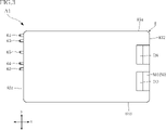
- FIG. 3 is a plan view showing the semiconductor device according to the first embodiment;
- FIG. 4 is a diagram showing the resin member in imaginary lines in the plan view of FIG.
- FIG. 5 is an enlarged plan view of a part of FIG. 4 (near the first semiconductor element).
- FIG. 6 is an enlarged plan view of a part of FIG. 4 (near the second semiconductor element).
- 7 is a plan view of FIG. 4 omitting a plurality of control terminals, a plurality of detection terminals, a plurality of connection members, and a resin member.
- FIG. 8 is a plan view of FIG.
- FIG. 7 is omitting a part of the power wiring section and a plurality of signal wiring sections.
- FIG. 9 is a plan view of FIG. 8 with the insulating substrate omitted.
- 10 is a bottom view of the semiconductor device according to the first embodiment;
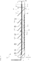
- FIG. 11 is a cross-sectional view along line XI-XI in FIG. 4.
- FIG. 12 is a cross-sectional view along line XII-XII in FIG.
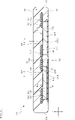
- FIG. 13 is a cross-sectional view along line XIII-XIII in FIG. 14 is a cross-sectional view taken along line XIV-XIV in FIG. 4.
- FIG. FIG. 15 is an enlarged cross-sectional view of a part of FIG. 14 (near the first semiconductor element).
- FIG. 16 is an enlarged cross-sectional view of a part of FIG. 14 (near the second semiconductor element).
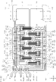
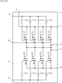
- 17 is a diagram illustrating a circuit configuration example of the semiconductor device according to the first embodiment
- FIG. FIG. 18 is a plan view showing the semiconductor device according to the second embodiment, and is a diagram showing a resin member with imaginary lines.
- FIG. 19 is a diagram illustrating a circuit configuration example of a semiconductor device according to a second embodiment
- FIG. 20 is a plan view showing the semiconductor device according to the third embodiment, and is a diagram showing a resin member with imaginary lines.
- FIG. 21 is a diagram illustrating a circuit configuration example of a semiconductor device according to a third embodiment;
- FIG. 22 is a plan view showing the semiconductor device according to the fourth embodiment, showing a resin member in imaginary lines.
- FIG. 23 is a diagram illustrating a circuit configuration example of a semiconductor device according to a fourth embodiment;
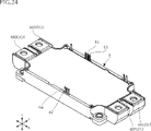
- FIG. 24 is a perspective view showing a semiconductor device according to a modification.
- 25 is a partially transparent plan view showing the semiconductor device shown in FIG. 24.
- a certain entity A is formed on a certain entity B
- a certain entity A is formed on (of) an entity B
- mean a certain entity A is directly formed in a certain thing B
- a certain thing A is formed in a certain thing B while another thing is interposed between a certain thing A and a certain thing B” including.
- ⁇ an entity A is arranged on an entity B'' and ⁇ an entity A is arranged on (of) an entity B'' mean ⁇ an entity A being placed directly on a certain thing B", and "a thing A being placed on a certain thing B with another thing interposed between something A and something B" include.
- ⁇ an object A is located on (of) an object B'' means ⁇ a certain object A is in contact with an object B, and an object A is located on an object B. Being located on (of)" and "something A is located on (something) B while another thing is interposed between something A and something B including "things”.
- ⁇ a certain object A overlaps an object B when viewed in a certain direction'' means ⁇ a certain object A overlaps all of an object B'', and ⁇ a certain object A overlaps an object B.'' It includes "overlapping a part of a certain thing B".
- the semiconductor device A1 includes a plurality of first semiconductor elements 1, a plurality of second semiconductor elements 2, a plurality of circuit components 3, a supporting member 4, an insulating substrate 50, a plurality of power wiring portions 511 to 514, and a plurality of signal wiring portions 52. 56, a pair of control terminals 61 and 62, a plurality of detection terminals 63 to 65, a plurality of connection members 7, and a resin member 8.
- the multiple connection members 7 include multiple connection members 71 , 72 , 731 , 732 , 741 , and 742 .
- the resin member 8 is indicated by an imaginary line (chain double-dashed line).
- the thickness direction of the plurality of first semiconductor elements 1 and the plurality of second semiconductor elements 2 will be referred to as "thickness direction z".
- plane view means when viewed in the thickness direction z.
- One direction perpendicular to the thickness direction z is called a "first direction x”.
- the first direction x is, for example, the horizontal direction in the plan view of the semiconductor device A1 (see FIGS. 3 and 4).
- a direction orthogonal to the thickness direction z and the first direction x is called a "second direction y”.
- the second direction y is, for example, the vertical direction in the plan view of the semiconductor device A1 (see FIGS. 3 and 4).
- Each of the plurality of first semiconductor elements 1 and the plurality of second semiconductor elements 2 is, for example, a MOSFET.
- Each of the plurality of first semiconductor elements 1 and the second semiconductor elements 2 is a field effect transistor including a MISFET (Metal-Insulator-Semiconductor FET) or another switching element such as a bipolar transistor including an IGBT instead of a MOSFET. There may be.
- Each of the plurality of first semiconductor elements 1 and the plurality of second semiconductor elements 2 is configured using SiC (silicon carbide).
- the semiconductor material is not limited to SiC, and may be Si (silicon), GaAs (gallium arsenide), GaN (gallium nitride), Ga 2 O 3 (gallium oxide), or the like.
- Each of the plurality of first semiconductor elements 1 has an element main surface 10a and an element rear surface 10b, as shown in FIG.
- the element main surface 10a and the element back surface 10b are separated from each other in the thickness direction z.
- the element main surface 10a faces one direction (upward) in the thickness direction z
- the element rear surface 10b faces the other direction (downward) in the thickness direction z.
- the element main surface 10a is an example of a "first element main surface”
- the element back surface 10b is an example of a "first element back surface”.
- Each of the plurality of first semiconductor elements 1 has a first electrode 11, a second electrode 12 and a third electrode 13, as shown in FIGS.
- the first electrode 11 is the drain
- the second electrode 12 is the source
- the third electrode 13 is the gate.
- the second electrode 12 includes a first power pad 121 and two first sensing pads 122.
- the first power pad 121 is used for main current conduction which will be detailed later.
- Each first detection pad 122 is used to detect a first detection signal corresponding to the conduction state of the second electrode 12 .
- the first detection signal is, for example, a voltage signal corresponding to the source current flowing through the second electrode 12 .
- Each first sense pad 122 is source sense.
- the first electrode 11 is arranged on the element back surface 10b, and the second electrode 12 (the first power pad 121 and the two first detection pads 122). and the third electrode 13 are arranged on the element main surface 10a.
- the first power pad 121, the two first detection pads 122 and the third electrode 13 are separated from each other.
- the two first detection pads 122 are arranged with the third electrode 13 interposed therebetween in the first direction x.
- the second electrode 12 of each first semiconductor element 1 is composed of one pad instead of including a first power pad 121 and two first detection pads 122. good too.
- each first semiconductor element 1 switches between a conductive state and a cutoff state according to the first drive signal.
- the operation of switching between the conductive state and the cutoff state is called a switching operation.
- In the conducting state current flows from the first electrode 11 (drain) to the second electrode 12 (source), and in the blocking state this current does not flow. That is, each first semiconductor element 1 is turned on between the first electrode 11 (drain) and the second electrode 12 (source) by a first drive signal (for example, gate voltage) input to the third electrode 13 (gate). / off controlled.
- the switching frequency of each first semiconductor element 1 depends on the frequency of the first drive signal.
- the first electrodes 11 are electrically connected to each other and the second electrodes 12 are electrically connected to each other by a configuration described in detail later. Thereby, the plurality of first semiconductor elements 1 are electrically connected in parallel as shown in FIG.
- the semiconductor device A1 inputs a common first drive signal to the plurality of first semiconductor elements 1 connected in parallel to cause the plurality of first semiconductor elements 1 to operate in parallel.
- the plurality of first semiconductor elements 1 are arranged in the first direction x, as shown in FIGS. 2, 4 and 7-9. As shown in FIG. 15, each first semiconductor element 1 is bonded to a supporting member 4 (a conductive plate 41 to be described later) via a conductive bonding material 19 .
- the conductive bonding material 19 is, for example, solder, metal paste material, or sintered metal.
- the plurality of first semiconductor elements 1 includes a pair of first outer elements 1A and one or more first inner elements 1B.
- the plurality of first semiconductor elements 1 includes two first inner elements 1B.
- the pair of first outer elements 1A are elements positioned at both ends of the plurality of first semiconductor elements 1 in the first direction x.
- the first inner element 1B is an element positioned between the pair of first outer elements 1A in the first direction x among the plurality of first semiconductor elements 1 .
- Each of the plurality of second semiconductor elements 2 has an element main surface 20a and an element back surface 20b, as shown in FIG.
- the element main surface 20a and the element back surface 20b are separated from each other in the thickness direction z.
- the element main surface 20a faces one direction (upward) in the thickness direction z, and the element back surface 20b faces the other direction (downward) in the thickness direction z.
- the element main surface 20a is an example of a "second element main surface”
- the element rear surface 20b is an example of a "second element rear surface”.
- Each of the plurality of second semiconductor elements 2 has a fourth electrode 21, a fifth electrode 22 and a sixth electrode 23, as shown in FIGS.
- the fourth electrode 21 is the drain
- the fifth electrode 22 is the source
- the sixth electrode 23 is the gate.
- the fifth electrode 22 includes a second power pad 221 and two second sensing pads 222. As shown in FIG.
- the second power pad 221 is used for main current conduction which will be detailed later.
- Each second detection pad 222 is used to detect a second detection signal according to the conduction state of the fifth electrode 22 .
- the second detection signal is, for example, a voltage signal corresponding to the source current flowing through the fifth electrode 22 .
- Each second sense pad 222 is source sense.
- the fourth electrode 21 is arranged on the element back surface 20b, and the fifth electrode 22 (second power pad 221 and two second detection pads 222) and the sixth electrode 23 are arranged on the element main surface 20a.
- the second power pad 221, the two second detection pads 222 and the sixth electrode 23 are separated from each other.
- the two second detection pads 222 are arranged on both sides of the sixth electrode 23 in the first direction x.
- the fifth electrode 22 of each second semiconductor element 2 may be composed of one pad instead of including the second power pad 221 and two second detection pads 222. good.
- each second semiconductor element 2 switches between a conductive state and a cut-off state according to the second drive signal.
- the operation of switching between the conductive state and the cutoff state is called a switching operation.
- In the conducting state current flows from the fourth electrode 21 (drain) to the fifth electrode 22 (source), and in the blocking state this current does not flow. That is, each second semiconductor element 2 is turned on between the fourth electrode 21 (drain) and the fifth electrode 22 (source) by the second drive signal (for example, gate voltage) input to the sixth electrode 23 (gate). / off controlled.
- the switching frequency of each second semiconductor element 2 depends on the frequency of the second drive signal.
- the fourth electrodes 21 are electrically connected to each other and the fifth electrodes 22 are electrically connected to each other by a configuration described in detail later. Thereby, the plurality of second semiconductor elements 2 are electrically connected in parallel as shown in FIG.
- a common second drive signal is input to the plurality of second semiconductor elements 2 connected in parallel to operate the plurality of second semiconductor elements 2 in parallel.
- the plurality of second semiconductor elements 2 are arranged in the first direction x, as shown in FIGS. 2, 4 and 7-9. As shown in FIG. 16, each second semiconductor element 2 is bonded to a supporting member 4 (a conductive plate 42 to be described later) via a conductive bonding material 29 .
- the conductive bonding material 29 is, for example, solder, metal paste material, or sintered metal.
- the plurality of second semiconductor elements 2 includes a pair of second outer elements 2A and one or more second inner elements 2B, as shown in FIGS. 4 and 7-9.
- the plurality of second semiconductor elements 2 includes two second inner elements 2B.
- the pair of second outer elements 2A are elements positioned at both ends of the plurality of second semiconductor elements 2 in the first direction x.
- the second inner element 2B is an element positioned between the pair of second outer elements 2A in the first direction x among the plurality of second semiconductor elements 2 .
- the semiconductor device A1 is configured, for example, as a half-bridge switching circuit. As described above, the plurality of first semiconductor elements 1 are connected in parallel to form the upper arm circuit of the semiconductor device A1. As described above, the plurality of second semiconductor elements 2 are connected in parallel to form the lower arm circuit of the semiconductor device A1. Each first semiconductor element 1 and each second semiconductor element 2 are electrically connected to each other by electrically connecting the second electrode 12 (source) and the fourth electrode 21 (drain). The second semiconductor element 2 is connected in series. Each first semiconductor element 1 and each second semiconductor element 2 form a bridge through this series connection. In the illustrated example, the semiconductor device A1 comprises four first semiconductor elements 1 and four second semiconductor elements 2 (see FIG. 4). The number of each of the first semiconductor element 1 and the number of the second semiconductor element 2 is not limited to this configuration, and can be changed as appropriate according to the performance required of the semiconductor device A1.
- a plurality of circuit components 3 are arranged on an insulating substrate 50 .
- each of the plurality of circuit components 3 is, for example, a ferrite bead.
- a ferrite bead is an inductance element that increases the impedance of high frequency signals (current) relative to low frequency signals.
- Each of the plurality of circuit components 3 is of the surface mount type in the illustrated example, but may be of the lead type instead of the surface mount type.
- the multiple circuit components 3 include multiple first circuit components 3A and multiple second circuit components 3B, as shown in FIGS.
- the plurality of first circuit components 3A are connected to the first conducting member.
- the first conductive member is electrically connected to the control terminal 61 and electrically interposed between the third electrodes 13 of the plurality of first semiconductor elements 1 .
- the first conduction member is a transmission path for the first drive signal.
- the first conductive member includes, for example, part of the signal wiring portion 52 and a plurality of connection members 731 .
- the third electrodes 13 of the plurality of first semiconductor elements 1 are electrically connected to each other through at least one of the plurality of first circuit components 3A.
- the plurality of first circuit components 3A increase impedance in the first frequency band.
- the first frequency band is higher than the switching frequency of each first semiconductor element 1 .
- the first frequency band includes, for example, resonance frequencies of a resonance circuit formed including parasitic inductance of the first conducting member.
- This resonant circuit further includes the parasitic capacitance (drain-gate capacitance) of each first semiconductor element 1 in the semiconductor device A1.
- a plurality of second circuit components 3B are connected to the second conducting member.
- the second conductive member is electrically connected to the control terminal 62 and electrically interposed between the sixth electrodes 23 of the plurality of second semiconductor elements 2 .
- the second conduction member is a transmission path for the second drive signal.
- the second conductive member includes, for example, part of the signal wiring portion 53 and a plurality of connection members 732 .
- the sixth electrodes 23 of the plurality of second semiconductor elements 2 are electrically connected to each other via at least one of the plurality of second circuit components 3B.
- a plurality of second circuit components 3B increase the impedance in the second frequency band.
- the second frequency band is higher than the switching frequency of each second semiconductor element 2 .
- the second frequency band includes, for example, resonance frequencies of a resonance circuit formed including parasitic inductance of the second conductive member.
- This resonant circuit further includes the parasitic capacitance (drain-gate capacitance) of each second semiconductor element 2 in the semiconductor device A1.
- the switching frequency of each first semiconductor element 1 and the switching frequency of each second semiconductor element 2 are the same, and the plurality of first circuit components 3A and the plurality of second circuit components 3B are of the same type. using things. Therefore, the first frequency band and the second frequency band are the same. Even when the switching frequency of each first semiconductor element 1 and the switching frequency of each second semiconductor element 2 are the same, the first frequency band and the second frequency band may be different. Moreover, when the switching frequency of each first semiconductor element 1 and the switching frequency of each second semiconductor element 2 are different, the first frequency band and the second frequency band may be the same or different.
- the support member 4 supports the plurality of first semiconductor elements 1 and the plurality of second semiconductor elements 2 as shown in FIGS. 9 and 14-16.
- the support member 4 has a pair of conductive plates 41 and 42 and a pair of insulating plates 43 and 44, as shown in FIGS. 9 and 11-16.
- Each of the pair of conductive plates 41 and 42 is made of a conductive material, such as copper or copper alloy. Different from this configuration, each of the conductive plates 41 and 42 may be a laminate in which a layer made of copper and a layer made of molybdenum are alternately laminated in the thickness direction z. In this case, both surface layers in the thickness direction z of each of the conductive plates 41 and 42 are layers made of copper.
- Each of the conductive plates 41 and 42 has, for example, a rectangular shape in plan view, as shown in FIG.
- the conductive plate 41 has a plurality of first semiconductor elements 1 mounted thereon and supports the plurality of first semiconductor elements 1 .
- the conductive plate 41 is electrically connected to the first electrode 11 (drain) of each first semiconductor element 1 .
- the first electrodes 11 of the plurality of first semiconductor elements 1 are electrically connected to each other via the conductive plate 41 .
- Conductive plate 41 has, for example, a rectangular parallelepiped shape.
- the dimension along the thickness direction z of the conductive plate 41 is larger than the dimension along the thickness direction z of the insulating substrate 50 .
- the conductive plate 41 is an example of the "first mounting portion".
- the conductive plate 41 as shown in FIGS. 9, 14 and 15, has a mounting surface 41a.
- the mounting surface 41a faces one side (upward) in the thickness direction z.
- each first semiconductor element 1 is joined and the power wiring portion 511 is joined.
- the conductive plate 41 is bonded to the insulating plate 43 via a bonding material 419, as shown in FIGS.
- the bonding material 419 may be conductive or insulating.
- the conductive plate 42 is mounted with a plurality of second semiconductor elements 2 and supports the plurality of second semiconductor elements 2, as shown in FIGS.
- the conductive plate 42 is electrically connected to the fourth electrode 21 (drain) of each second semiconductor element 2 .
- the fourth electrodes 21 of the plurality of second semiconductor elements 2 are electrically connected to each other via the conductive plate 42 .
- Conductive plate 42 has, for example, a rectangular parallelepiped shape.
- the dimension along the thickness direction z of the conductive plate 42 is larger than the dimension along the thickness direction z of the insulating substrate 50 .
- the conductive plate 42 is an example of a "second mounting portion".
- the conductive plate 42 as shown in FIGS. 9, 14 and 16, has a mounting surface 42a.
- the mounting surface 42a faces one side (upward) in the thickness direction z.
- each second semiconductor element 2 is joined, and the power wiring portion 514 is also joined.
- the conductive plate 42 is bonded to the insulating plate 44 via a bonding material 429, as shown in FIGS. Bonding material 429 may be conductive or insulating.
- Each of the pair of insulating plates 43 and 44 is made of an insulating material, such as Al 2 O 3 (aluminum oxide).
- Each insulating plate 43, 44 has, for example, a rectangular shape in plan view, as shown in FIG. As shown in FIGS. 9, 14 and 15, insulating plate 43 supports conductive plate 41 . As shown in FIGS. 9, 14 and 16, insulating plate 44 supports conductive plate 42 .
- a plating layer may be formed on the surfaces of the insulating plates 43 and 44 to which the conductive plates 41 and 42 are joined.
- the plated layer is made of silver or a silver alloy, for example.
- the surfaces of the insulating plates 43 and 44 facing the other (downward) direction in the thickness direction z are exposed from the resin member 8 (resin back surface 82 described later), but are covered with the resin member 8 .
- the insulating substrate 50 is made of an insulating material, such as a glass epoxy resin.
- the insulating substrate 50 may be made of ceramics such as AlN (aluminum nitride), SiN (silicon nitride), and Al 2 O 3 instead of glass epoxy resin.
- the insulating substrate 50 has a main surface 501 and a back surface 502, as shown in FIGS.
- the main surface 501 and the back surface 502 are spaced apart in the thickness direction z.
- the main surface 501 faces one direction (upward) in the thickness direction z, and the back surface 502 faces the other direction (downward) in the thickness direction z.
- the main surface 501 is an example of a "substrate main surface”
- the back surface 502 is an example of a "substrate back surface”.
- the insulating substrate 50 includes a plurality of through-holes 503, a through-hole 504, a plurality of openings 505 and a plurality of openings 506, as shown in FIGS. 8 and 13-16.
- Each of the plurality of through holes 503 penetrates the insulating substrate 50 from the main surface 501 to the back surface 502 in the thickness direction z, as shown in FIG.
- each metal member 59 is inserted into each through hole 503 .
- the inner surface of each through-hole 503 is not in contact with each metal member 59 as shown in FIGS. 8 and 13 .
- the inner surface of each through hole 503 may be in contact with each metal member 59 .
- "inserted" means a state in which a certain member (for example, each metal member 59) is inserted into a certain through hole (for example, each through hole 503), and a certain member is inserted on the inner surface of the certain through hole. Whether they are in contact or not is not limited.
- An insulating member different from the insulating substrate 50 may be formed in the gap between each metal member 59 and the through hole 503 .
- the through hole 504 penetrates the insulating substrate 50 from the main surface 501 to the back surface 502 in the thickness direction z.
- a metal member 58 is inserted into the through hole 504 as shown in FIG.
- the inner surface of the through-hole 504 is in contact with the metal member 58 (see FIG. 8), but it does not have to be in contact.
- each of the plurality of openings 505 penetrates the insulating substrate 50 from the main surface 501 to the back surface 502 in the thickness direction z. As shown in FIG. 8, each opening 505 surrounds each first semiconductor element 1 in plan view. Each opening 505 is an example of a "first opening”.
- each of the plurality of openings 506 penetrates the insulating substrate 50 from the main surface 501 to the back surface 502 in the thickness direction z. As shown in FIG. 8, each opening 506 surrounds each second semiconductor element 2 in plan view. Each opening 506 is an example of a "second opening”.
- the plurality of power wiring portions 511 to 514 and the plurality of signal wiring portions 52 to 56 are part of the support member 4 (the conductive plates 41 and 42), the plurality of metal members 58 and 59, and the plurality of connection members 7, together with the semiconductor device. form a conductive path in A1.
- the plurality of power wiring sections 511-514 and the plurality of signal wiring sections 52-56 are separated from each other.
- the plurality of power wiring portions 511-514 and the plurality of signal wiring portions 52-56 are made of copper or a copper alloy, for example.
- Each thickness (dimension in the thickness direction z) and each constituent material of the plurality of power wiring portions 511 to 514 and the plurality of signal wiring portions 52 to 56 are the specifications of the semiconductor device A1 (rated current, allowable current, rated voltage, Withstand voltage, internal inductance of the entire device, size of the device, etc.).
- a plurality of power wiring portions 511 to 514 constitute conduction paths for the main current in the semiconductor device A1.
- the power wiring portions 511 and 512 overlap each other in plan view
- the power wiring portions 513 and 514 overlap each other in plan view.
- the power wiring portion 511 is formed on the back surface 502 of the insulating substrate 50 .
- the power wiring portion 511 is joined to the mounting surface 41a of the conductive plate 41, as shown in FIGS.
- the power wiring portion 511 is electrically connected to each first electrode 11 (drain) of the plurality of first semiconductor elements 1 through the conductive plate 41 .
- the power wiring section 511 includes a plurality of openings 511a and through holes 511b, as shown in FIGS. As shown in FIGS. 14 and 15, each of the plurality of openings 511a penetrates the power wiring portion 511 in the thickness direction z. As can be understood from FIGS. 14 and 15, the plurality of openings 511a overlap each opening 505 of the insulating substrate 50 in plan view. As shown in FIG. 9, each opening 511a surrounds each first semiconductor element 1 in plan view.
- the through hole 511b penetrates the power wiring portion 511 in the thickness direction z. As shown in FIG. 9, the metal member 58 is fitted in the through hole 511b, and the inner surface of the through hole 511b is in contact with the metal member 58. As shown in FIG.
- “fitted” means a state in which a certain member (for example, the metal member 58) is inserted into a certain through hole (for example, the through hole 511b), and the certain member is in contact with the inner surface of the certain through hole.
- the "inserted” state corresponds to the state of being in contact with the inner surface of the through-hole among the "inserted” states.
- the power wiring portion 512 is formed on the main surface 501 of the insulating substrate 50 . As understood from FIGS. 4 and 6, the power wiring portion 512 is electrically connected to the fifth electrode 22 (source) of each second semiconductor element 2 via a plurality of connection members 72 . The power wiring portion 512 is formed so as to avoid each of the plurality of first semiconductor elements 1 in plan view.
- the power wiring portion 513 is formed on the main surface 501 of the insulating substrate 50 .
- the power wiring portion 513 is located on one side (lower side in FIG. 6) in the second direction y than the power wiring portion 512 in plan view.
- the power wiring portion 513 is electrically connected to the second electrode 12 (source) of each first semiconductor element 1 via a plurality of connection members 71 .
- the power wiring portion 513 is electrically connected to the fourth electrode 21 (drain) of each second semiconductor element 2 via the power wiring portion 514 and each metal member 59 by a structure described in detail later.
- the power wiring portion 513 is formed so as to avoid each of the plurality of second semiconductor elements 2 in plan view.
- the power wiring part 513 includes a plurality of through holes 513a, as shown in FIGS. As shown in FIG. 13, the plurality of through holes 513a penetrate through the power wiring portion 513 in the thickness direction z. As shown in FIGS. 7 and 13 , a plurality of metal members 59 are fitted in each through hole 513 a , and the inner surface of each through hole 513 a is in contact with each metal member 59 . In the illustrated example, each through-hole 513 a is circular in plan view (see FIG. 7 ), but may be changed as appropriate according to the shape of each metal member 59 .
- the power wiring portion 514 is formed on the back surface 502 of the insulating substrate 50 .
- the power wiring portion 514 is joined to the mounting surface 42a of the conductive plate 42, as shown in FIGS.
- the power wiring portion 514 is electrically connected to each fourth electrode 21 (drain) of the plurality of second semiconductor elements 2 through the conductive plate 42 .
- the power wiring portion 514 is electrically connected to the second electrode 12 (source) of each first semiconductor element 1 through the power wiring portion 513 and each metal member 59 by a configuration described in detail later.
- the power wiring portion 514 includes a plurality of openings 514a and a plurality of through holes 514b, as shown in FIGS. 9, 13, 14 and 16. As shown in FIGS. 14 and 16, each of the plurality of openings 514a penetrates the power wiring portion 514 in the thickness direction z. 14 and 16, the plurality of openings 514a overlap each opening 506 of the insulating substrate 50 in plan view. As shown in FIG. 9, each opening 514a surrounds each second semiconductor element 2 in plan view. As shown in FIG. 13, each of the plurality of through holes 514b penetrates the power wiring portion 514 in the thickness direction z. As can be understood from FIG. 13, each through hole 514b overlaps each through hole 513a of the power wiring portion 513 in plan view. A plurality of metal members 59 are fitted one by one in each through hole 514b.
- the semiconductor device A1 includes a first power terminal portion 5P, a second power terminal portion 5N and two third power terminal portions 5O.
- the first power terminal portion 5P and the second power terminal portion 5N are connected to, for example, an external DC power supply, and are applied with a power supply voltage (DC voltage).
- the first power terminal portion 5P is a P terminal connected to the positive electrode of the DC power supply
- the second power terminal portion 5N is the N terminal connected to the negative electrode of the DC power supply.
- the DC voltage applied to the first power terminal portion 5P and the second power terminal portion 5N is converted into an AC voltage by each switching operation of the plurality of first semiconductor elements 1 and each switching operation of the plurality of second semiconductor elements 2. be done.
- the converted voltage (AC voltage) is output from each of the two third power terminal portions 5O.
- the main current in the semiconductor device A1 is generated by this power supply voltage and the converted voltage.
- the first power terminal portion 5P is part of the power wiring portion 511, as shown in FIGS. Therefore, the power wiring portion 511 includes the first power terminal portion 5P. As shown in FIGS. 4, 7, and 9 to 11, the first power terminal portion 5P is located at one end (the right side in FIG. 4) of the power wiring portion 511 in the first direction x. . Since the first power terminal portion 5 ⁇ /b>P is a part of the power wiring portion 511 , it is electrically connected to each first electrode 11 (drain) of the plurality of first semiconductor elements 1 .
- the second power terminal portion 5N is part of the power wiring portion 512, as shown in FIGS. Therefore, the power wiring portion 512 includes the second power terminal portion 5N. As shown in FIGS. 2 to 4, 7 and 11, the second power terminal portion 5N is located at one end (the right side in FIG. 4) of the power wiring portion 512 in the first direction x. . Since the second power terminal portion 5N is part of the power wiring portion 512, it is electrically connected to the fifth electrode 22 (source) of each second semiconductor element 2. As shown in FIG.
- the power wiring portion 513 includes one of the two third power terminal portions 5O.
- one of the two third power terminal portions 5O is the end of the power wiring portion 513 on one side in the first direction x (right side in FIG. 4). located in the department.
- the other of the two third power terminal portions 5O is part of the power wiring portion 514 as shown in FIGS. Therefore, the power wiring portion 514 includes the other of the two third power terminal portions 5O. 4, 7, 9, 10 and 12, the other of the two third power terminal portions 5O is located on one side of the power wiring portion 514 in the first direction x (the right side in FIG. 4).
- the second electrode 12 (source) of each first semiconductor element 1 and each second semiconductor It is electrically connected to the fourth electrode 21 (drain) of the element 2 .
- the first power terminal portion 5P, the second power terminal portion 5N and the two third power terminal portions 5O are spaced apart from each other and are each separated from the resin member 8 as shown in FIGS. expose. Each surface of the first power terminal portion 5P, the second power terminal portion 5N and the two third power terminal portions 5O may or may not be plated.
- the semiconductor device A1 includes two third power terminal portions 5O, but unlike this configuration, it may include only one of the two third power terminal portions 5O.
- a plurality of signal wiring portions 52 to 56 form conduction paths for control signals in the semiconductor device A1.
- a plurality of signal wiring portions 52 to 56 are formed on main surface 501 of insulating substrate 50, as shown in FIGS.
- the signal wiring portion 52 is electrically connected to the control terminal 61 .
- the signal wiring portion 52 is electrically connected to each third electrode 13 of the plurality of first semiconductor elements 1 .
- the signal wiring portion 52 forms a transmission path for transmitting the first drive signal together with the plurality of connection members 731 .
- the signal wiring portion 52 is an example of a “first signal wiring portion”.
- the signal wiring portion 52 includes a joint portion 521, a plurality of individual portions 522 and an extension portion 523.
- the control terminal 61 is joined to the joining portion 521, as shown in FIGS. As shown in FIGS. 4 and 7, the joint portion 521 is located at the end portion of the insulating substrate 50 on the other side in the first direction x (the left side in FIG. 4) in plan view.
- the joint portion 521 is electrically connected to the plurality of individual portions 522 .
- the joint 521 is an example of a "first joint".
- the plurality of individual parts 522 are arranged along the first direction x and spaced apart from each other, as shown in FIGS. As shown in FIGS. 4 and 7, each of the individual portions 522 has a strip shape extending in the first direction x in plan view. As shown in FIGS. 4, 7, and 11, each of the plurality of individual portions 522 is joined to one of the plurality of connection members 731 and is joined to one of the plurality of first circuit components 3A. Two individual parts 522 adjacent to each other in the first direction x are electrically connected via the first circuit component 3A. As shown in FIGS.
- the plurality of individual portions 522 are located on the side opposite to the side on which the plurality of second semiconductor elements 2 are located with respect to the plurality of first semiconductor elements 1 in the second direction y (see FIG. 7). 4).
- the plurality of individual portions 522 are positioned on one side (the right side in FIG. 4) in the first direction x from the joint portion 521 .
- Each individual part 522 is an example of a "first individual part”.
- the extending portion 523 extends from the joint portion 521 to any one of the plurality of individual portions 522 .
- the extending portion 523 electrically connects the joint portion 521 and one of the plurality of individual portions 522 .
- the extending portion 523 is connected to the individual portion 522 closest to the joint portion 521 in the first direction x among the plurality of individual portions 522 .
- the individual portion 522 connected to the extension portion 523 is located on the other side (left side in FIG. 4 ) of the plurality of individual portions 522 in the first direction x.
- the signal wiring portion 53 is electrically connected to the control terminal 62 .
- the signal wiring portion 53 is electrically connected to each sixth electrode 23 of the plurality of second semiconductor elements 2 .
- the signal wiring portion 53 forms a transmission path for transmitting the second drive signal together with the plurality of connection members 732 .
- a plurality of second circuit components 3B are joined to the signal wiring portion 53 .
- the signal wiring portion 53 is an example of a “second signal wiring portion”. As shown in FIGS. 4 , 7 and 12 , the signal wiring portion 53 includes a joint portion 531 , a plurality of individual portions 532 and extension portions 533 .
- the control terminal 61 is joined to the joining portion 531 as shown in FIG. As shown in FIGS. 4 and 7, the joint portion 531 is located at the end portion of the insulating substrate 50 on the other side in the first direction x (the left side in FIG. 4) in plan view.
- the joint portion 531 is electrically connected to the plurality of individual portions 532 .
- the joint 531 is an example of a "second joint".
- the plurality of individual parts 532 are arranged along the first direction x and spaced apart from each other, as shown in FIGS. As shown in FIGS. 4 and 7, each of the individual portions 532 has a strip shape extending in the first direction x in plan view. As shown in FIGS. 4, 7 and 12, each of the plurality of individual portions 532 is joined to one of the plurality of connection members 732 and is joined to one of the plurality of second circuit components 3B. Two individual portions 532 adjacent to each other in the first direction x are electrically connected via the second circuit component 3B. As shown in FIGS.
- the plurality of individual portions 532 are located on the side opposite to the side on which the plurality of first semiconductor elements 1 are located with respect to the plurality of second semiconductor elements 2 in the second direction y (see FIG. 7). 4).
- the plurality of individual portions 532 are positioned on one side (the right side in FIG. 4) in the first direction x from the joint portion 531 .
- Each individual part 532 is an example of a "second individual part”.
- the extending portion 533 extends from the joint portion 531 to any one of the plurality of individual portions 532 .
- the extending portion 533 electrically connects the joint portion 531 and one of the plurality of individual portions 532 .
- the extending portion 533 is connected to the individual portion 532 closest to the joint portion 531 in the first direction x among the plurality of individual portions 532 .
- the individual portion 532 connected to the extending portion 533 is located on the other side of the first direction x (left side in FIG. 4 ) among the plurality of individual portions 532 .
- most of the extending portion 533 is strip-shaped extending in the second direction y in plan view.
- the signal wiring portion 54 is electrically connected to the detection terminal 63 .
- the signal wiring portion 54 is electrically connected to each second electrode 12 of the plurality of first semiconductor elements 1 .
- the signal wiring portion 54 forms a transmission path for transmitting the first detection signal together with the plurality of connection members 741 .
- the signal wiring portion 54 includes a joint portion 541 , a strip portion 542 , a plurality of pad portions 543 and an extension portion 544 .
- joint portion 541, strip portion 542, a plurality of pad portions 543, and extension portion 544 are integrally formed.
- the joint portion 541 is joined with the detection terminal 63 as shown in FIG.
- the joint portion 541 is an end portion of the insulating substrate 50 in plan view, and is located at the end portion on the other side in the first direction x (the left side in FIG. 4).
- the band-shaped portion 542 extends in the first direction x in plan view.
- the belt-like portion 542 has the first direction x as its longitudinal direction.
- the band-shaped portion 542 is located on one side (upper side in FIG. 4) in the second direction y of the plurality of first semiconductor elements 1 in plan view.
- the belt-like portion 542 is sandwiched between the plurality of first semiconductor elements 1 and the plurality of individual portions 522 in the second direction y in plan view.
- the belt-like portion 542 is located on one side (the right side in FIG. 4) in the first direction x relative to the joint portion 541 .
- the plurality of pad portions 543 are formed between two first semiconductor elements 1 adjacent to each other in the first direction x in plan view.
- the plurality of pad portions 543 are arranged between one of the pair of first outer elements 1A and the adjacent first inner element 1B, and between the other of the pair of first outer elements 1A.
- One each is arranged between the adjacent first inner element 1B and between two first inner elements 1B.
- Each of the plurality of pad portions 543 is joined to two connecting members 741 as shown in FIGS. 4 and 5 .
- Each of the plurality of pad portions 543 is connected to the band-shaped portion 542.
- the edge of the band-shaped portion 542 is the edge on the side where the plurality of first semiconductor elements 1 are positioned in the second direction y. connected to.
- Each of the plurality of pad portions 543 overlaps the strip portion 542 when viewed in the second direction y.
- Each pad portion 543 may be separate from the strip portion 542, unlike the illustrated example. In this case, each pad portion 543 and the belt-shaped portion 542 may be electrically connected by using, for example, a bonding wire.
- the extending portion 544 extends from the joint portion 541 to the strip portion 542 as shown in FIGS.
- the extending portion 544 electrically connects the joint portion 541 and the strip portion 542 .
- the signal wiring portion 55 is electrically connected to the detection terminal 64 .
- the signal wiring portion 55 is electrically connected to each second electrode 12 of the plurality of second semiconductor elements 2 .
- the signal wiring portion 55 forms a transmission path for transmitting the second detection signal together with the plurality of connection members 742 .
- the signal wiring portion 55 includes a joint portion 551 , a strip portion 552 , a plurality of pad portions 553 and an extension portion 554 .
- the joint portion 551, the strip portion 552, the plurality of pad portions 553, and the extension portion 554 are integrally formed.
- the joint portion 551 is joined with the detection terminal 64 as shown in FIG.
- the joint portion 551 is an end portion of the insulating substrate 50 in plan view, and is located at the end portion on the other side in the first direction x (the left side in FIG. 4).
- the band-shaped portion 552 extends in the first direction x in plan view.
- the belt-like portion 552 has the first direction x as its longitudinal direction.
- the band-shaped portion 552 is located on the other side (lower side in FIG. 4) in the second direction y of the plurality of second semiconductor elements 2 in plan view.
- the belt-like portion 552 is sandwiched between the plurality of second semiconductor elements 2 and the plurality of individual portions 532 in the second direction y in plan view.
- the belt-like portion 552 is located on one side (the right side in FIG. 4) in the first direction x relative to the joint portion 551 .
- the band-shaped portion 552 is parallel (or substantially parallel) to the band-shaped portion 542 in plan view.
- the plurality of pad portions 553 are formed between two second semiconductor elements 2 adjacent to each other in the first direction x in plan view.
- the plurality of pad portions 553 are arranged between one of the pair of second outer elements 2A and the second inner element 2B adjacent thereto, and between the pair of second outer elements 2A. and the second inner element 2B adjacent thereto, and between two second inner elements 2B.
- Each of the plurality of pad portions 553 is joined to two connection members 742 as shown in FIGS. 4 and 6 .
- Each of the plurality of pad portions 553 is connected to the band-shaped portion 552.
- the edge of the band-shaped portion 542 is the edge on the side where the plurality of second semiconductor elements 2 are positioned in the second direction y. connected to.
- the plurality of pad portions 553 overlap the belt-like portion 552 when viewed in the second direction y.
- Each pad portion 553 may be separate from the strip portion 552, unlike the illustrated example.
- each pad portion 553 and the belt-shaped portion 552 may be electrically connected by, for example, a bonding wire.
- the extending portion 554 extends from the joint portion 551 to the strip portion 552 as shown in FIGS.
- the extending portion 554 electrically connects the joint portion 551 and the strip portion 552 .
- most of the extending portion 554 is strip-shaped extending in the second direction y.
- the signal wiring portion 56 is electrically connected to the detection terminal 65 .
- the signal wiring portion 56 is electrically connected to each first electrode 11 of the plurality of first semiconductor elements 1 .
- a through hole 561 is formed in the signal wiring portion 56 .
- the through hole 561 penetrates the signal wiring portion 56 in the thickness direction z.
- the metal member 58 is fitted in the through hole 561 .
- Each of the plurality of metal members 59 penetrates the insulating substrate 50 in the thickness direction z as shown in FIG.
- Each metal member 59 is, for example, columnar.
- the plan view shape of each metal member 59 is circular (see FIGS. 5 to 8), but the plan view shape of each metal member 59 may be elliptical or polygonal instead of circular.
- a constituent material of each metal member 59 is, for example, copper or a copper alloy.
- the plurality of metal members 59 are fitted into the through holes 513a of the power wiring section 513 and the through holes 514b of the power wiring section 514, respectively, and are fitted into the respective through holes 514b of the insulating substrate 50. It is inserted into the through hole 503 .
- Each metal member 59 is in contact with the inner surface of each through hole 513a and the inner surface of each through hole 514b.
- Each metal member 59 is supported by being fitted into each through hole 513a and each through hole 514b. At this time, if there are gaps between each metal member 59 and the inner surface of each through hole 513a and between each metal member 59 and the inner surface of each through hole 514b, solder should be poured into these gaps.
- this gap is filled with solder, and each metal member 59 is fixed to the power wiring portion 513 and the power wiring portion 514 .
- the gap between each metal member 59 and the inner surface of the through hole 503 of the insulating substrate 50 can also be filled with the solder.
- the metal member 58 penetrates the insulating substrate 50 in the thickness direction z, and electrically connects the power wiring portion 511 and the signal wiring portion 56 .
- Metal member 58 is, for example, columnar.
- the planar view shape of the metal member 58 is circular (see FIGS. 6 to 8), but the planar view shape of the metal member 58 may be elliptical or polygonal instead of circular.
- a constituent material of the metal member 58 is, for example, copper or a copper alloy.
- the metal member 58 is fitted into the through hole 561 of the signal wiring portion 56 and the through hole 511b of the power wiring portion 511, and is also inserted into the through hole 504 of the insulating substrate 50. .
- the metal member 58 is in contact with the inner surface of the through hole 561, the inner surface of the through hole 511b, and the inner surface of the through hole 504, as shown in FIGS.
- solder should be poured into the gaps.
- the gaps are filled with solder, and the metal members 58 are fixed to the power wiring portions 511 , the signal wiring portions 56 and the insulating substrate 50 .
- each first semiconductor element 1 is formed by each opening 505 of the insulating substrate 50, each opening 511a of the power wiring portion 511, and the conductive plate 41. is housed in a hollow
- the element main surface 10a of each first semiconductor element 1 is located on either the insulating substrate 50 or the power wiring portion 511 when viewed in a direction orthogonal to the thickness direction z (for example, the second direction y). Although it overlaps, it may overlap with the power wiring portion 512 . In either case, each first semiconductor element 1 does not protrude above the power wiring portion 512 in the thickness direction z.
- each second semiconductor element 2 has a recess formed by each opening 506 of the insulating substrate 50, each opening 514a of the power wiring portion 514, and the conductive plate 42. are housed in In the illustrated example, the element main surface 20a of each second semiconductor element 2 is located on either the insulating substrate 50 or the power wiring portion 514 when viewed in a direction orthogonal to the thickness direction z (for example, the second direction y). Although it overlaps, it may overlap with the power wiring portion 513 . In either case, each second semiconductor element 2 does not protrude above the power wiring portion 513 in the thickness direction z.
- the plurality of control terminals 61, 62 and the plurality of detection terminals 63-65 are each made of a conductive material. This electrically conductive material is, for example, copper or a copper alloy.
- the plurality of control terminals 61, 62 and the plurality of detection terminals 63-65 are formed by cutting out and bending a plate-shaped member. As shown in FIGS. 1 to 4, 10, etc., the plurality of control terminals 61 and 62 and the plurality of detection terminals 63 to 65 are more first semiconductor elements than the plurality of first semiconductor elements 1 and the plurality of second semiconductor elements 2, respectively. located on the other side of the direction x (left side in FIG. 4), and for the plurality of first semiconductor elements 1 and the plurality of second semiconductor elements 2, the first power terminal portion 5P, second power terminal portion 5N and It is positioned opposite to the two third power terminal portions 5O.
- control terminal 61 is electrically connected to the third electrode 13 (gate) of each first semiconductor element 1 .
- a control terminal 61 receives a first drive signal for controlling the switching operation of each first semiconductor element 1 .
- control terminal 61 includes a portion covered with resin member 8 and a portion exposed from resin member 8.
- a portion of the control terminal 61 covered with the resin member 8 is joined to the joint portion 521 of the signal wiring portion 52 .
- a portion of the control terminal 61 exposed from the resin member 8 is connected to an external control device (for example, a gate driver), and a first drive signal (gate voltage) is input from the control device.
- the control terminal 61 is an example of a "first control terminal".
- control terminal 62 is electrically connected to the sixth electrode 23 (gate) of each second semiconductor element 2 .
- a control terminal 62 receives a second drive signal for controlling the switching operation of each second semiconductor element 2 .
- control terminal 62 includes a portion covered with resin member 8 and a portion exposed from resin member 8 .
- a portion of the control terminal 62 covered with the resin member 8 is joined to the joint portion 531 of the signal wiring portion 53 .
- the control terminal 62 is an example of a "second control terminal".
- the detection terminal 63 is electrically connected to the second electrode 12 (source) of each first semiconductor element 1 .
- the detection terminal 63 outputs a first detection signal indicating the conduction state of each first semiconductor element 1 .
- the voltage applied to the second electrode 12 of each first semiconductor element 1 (voltage corresponding to the source current) is output from the detection terminal 63 as the first detection signal.
- detection terminal 63 includes a portion covered with resin member 8 and a portion exposed from resin member 8 .
- a portion of the detection terminal 63 covered with the resin member 8 is joined to the joint portion 541 of the signal wiring portion 54 .
- a portion of the detection terminal 63 exposed from the resin member 8 is connected to the external control device and outputs a first detection signal of the control device.
- the detection terminal 64 is electrically connected to the fifth electrode 22 (source) of each second semiconductor element 2 .
- the detection terminal 64 outputs a second detection signal indicating the conductive state of each second semiconductor element 2 .
- the voltage applied to the fifth electrode 22 of each second semiconductor element 2 (voltage corresponding to the source current) is output from the detection terminal 64 as the second detection signal.
- detection terminal 64 includes a portion covered with resin member 8 and a portion exposed from resin member 8 . A portion of the detection terminal 64 pressed by the resin member 8 is joined to the joint portion 551 of the signal wiring portion 55 . A portion of the detection terminal 64 exposed from the resin member 8 is connected to the external control device, and outputs a second detection signal to the control device.
- the detection terminal 65 is electrically connected to the first electrode 11 (drain) of each first semiconductor element 1 .
- the detection terminal 65 outputs the voltage applied to the first electrode 11 of each first semiconductor element 1 (voltage corresponding to the drain current).
- detection terminal 65 includes a portion covered with resin member 8 and a portion exposed from resin member 8 .
- a portion of the detection terminal 65 covered with the resin member 8 is joined to the signal wiring portion 56 .
- a portion of the detection terminal 65 exposed from the resin member 8 is connected to the external control device, and the voltage (corresponding to the drain current) applied to the first electrode 11 of each first semiconductor element 1 is applied to the control device. output voltage).
- Each of the plurality of connection members 7 conducts two parts separated from each other.
- the multiple connection members 7 include multiple connection members 71 , 72 , 731 , 732 , 741 , and 742 .
- Each of the plurality of connecting members 7 is, for example, a bonding wire.
- Some of the plurality of connection members 7 (for example, the plurality of connection members 71 and 72) may be metal plate materials instead of bonding wires.
- Each constituent material of the plurality of connecting members 7 may be gold, aluminum or copper.
- connection members 71 are respectively joined to the first power pads 121 of the second electrodes 12 (sources) of the plurality of first semiconductor elements 1 and the power wiring portion 513. , make them conductive. A main current in the semiconductor device A1 flows through the plurality of connection members 71 . Unlike the illustrated example, some connection members 71 may be joined to the upper surface of the metal member 59 instead of the power wiring portion 513 .
- the plurality of connection members 72 are respectively joined to the second power pads 221 of the fifth electrodes 22 (sources) of the plurality of second semiconductor elements 2 and the power wiring portion 512. , make them conductive. A main current in the semiconductor device A1 flows through the plurality of connection members 72 .
- the plurality of connection members 731 are respectively joined to the third electrodes 13 (gates) of the plurality of first semiconductor elements 1 and the individual portions 522 of the signal wiring portion 52, Make them conductive.
- the plurality of connection members 731 transmit the first drive signal together with the signal wiring portion 52 .
- Each connecting member 731 is part of the first conducting member.
- the connection member 731 connected to one first semiconductor element 1 and the connection member 731 connected to the other first semiconductor element 1 and portions of the signal wiring portion 52 to which the connection members 731 are connected constitute the first conducting member.
- Each connecting member 731 is an example of a "first connecting member".
- the plurality of connection members 732 are respectively joined to the sixth electrodes 23 (gates) of the plurality of second semiconductor elements 2 and the individual portions 532 of the signal wiring portion 53, Make them conductive.
- the plurality of connection members 732 transmit the second drive signal together with the signal wiring portion 53 .
- Each connecting member 732 is part of the second conducting member.
- the connection member 732 connected to one second semiconductor element 2 and the connection member 732 connected to the other second semiconductor element 2 constitute the second conductive member.
- Each connecting member 732 is an example of a "second connecting member".
- the direction in which each connection member 731 extends in a plan view has an inclination with respect to the arrangement direction (first direction x) of the plurality of first semiconductor elements 1. and greater than the inclination with respect to the direction (second direction y) orthogonal to the thickness direction z.
- the direction in which each connection member 732 extends in plan view is such that the inclination with respect to the arrangement direction (first direction x) of the plurality of second semiconductor elements 2 is equal to the arrangement direction and the thickness. It is larger than the inclination with respect to the direction (second direction y) perpendicular to the direction z.
- each of the plurality of connection members 741 is joined to each pad portion 543 (signal wiring portion 53) and the first semiconductor element 1 adjacent to the pad portion 543 in plan view, Make them conductive.
- Each connection member 741 is joined to the first detection pad 122 of the second electrode 12 (source) of each first semiconductor element 1, as shown in FIG.
- the connection member 741 joined to the first detection pad 122 on one side of each first semiconductor element 1 in the first direction x is the first semiconductor element 1 of the first semiconductor element 1 in plan view. It is joined to the pad portion 543 adjacent to one side in the direction x.
- connection member 741 joined to the first detection pad 122 on the other side in the first direction x of each first semiconductor element 1 is adjacent to the other side in the first direction x of the first semiconductor element 1 in plan view. It is joined to the pad part 543 which connects.
- a connecting member 741 is joined to one of the two first detection pads 122, and the plurality of first inner elements 1B In each, a connecting member 741 is joined to both of the two first detection pads 122 .
- a plurality of connection members 741 transmit the first detection signal.
- each connection member 741 is joined to the pad together with the connection member 71 .
- each of the plurality of connection members 742 is joined to each pad portion 553 (signal wiring portion 54) and the second semiconductor element 2 adjacent to the pad portion 553 in plan view, Make them conductive.
- Each connection member 742 is joined to the second detection pad 222 of the fifth electrode 22 (source) of each second semiconductor element 2, as shown in FIG.
- the connection member 742 joined to the second detection pad 222 on one side of each second semiconductor element 2 in the first direction x is the second semiconductor element 2 of the second semiconductor element 2 in plan view. It is joined to the pad portion 553 adjacent to one side in the direction x.
- connection member 742 joined to the second detection pad 222 on the other side in the first direction x of each second semiconductor element 2 is adjacent to the other side in the first direction x of the second semiconductor element 2 in plan view. It is joined to the pad part 553 which connects.
- a connecting member 742 is joined to one of the two second detection pads 222, and the plurality of second inner elements 2B In each, a connecting member 742 is joined to both of the two second sensing pads 222 .
- each connection member 742 is joined to the pad together with the connection member 72 .
- the direction in which each connection member 741 extends in a plan view has an inclination with respect to the arrangement direction (first direction x) of the plurality of first semiconductor elements 1. and smaller than the inclination with respect to the direction (second direction y) orthogonal to the thickness direction z.
- the direction in which each connection member 742 extends in plan view is such that the inclination with respect to the arrangement direction (first direction x) of the plurality of second semiconductor elements 2 is equal to the arrangement direction and the thickness. It is smaller than the inclination with respect to the direction (second direction y) perpendicular to the direction z.
- the wire diameters of the plurality of connection members 71, 72, 731, 732, 741, and 742 are not particularly limited, but in the semiconductor device A1, these wire diameters have the following relationship.
- Each wire diameter of the plurality of connection members 71 and 72 is larger than each wire diameter of the plurality of connection members 731 , 732 , 741 and 742 . This is because the main current flows through the connecting members 71 and 72 .
- each wire diameter of the plurality of connection members 741 and 742 is larger than each wire diameter of the plurality of connection members 731 and 732 .
- the resin member 8 is a sealing material that protects the plurality of first semiconductor elements 1, the plurality of second semiconductor elements 2, the plurality of circuit components 3, and the like.
- the resin member 8 is made of an insulating resin material.
- the resin material is, for example, black epoxy resin.
- the resin member 8 includes the plurality of first semiconductor elements 1, the plurality of second semiconductor elements 2, the plurality of circuit components 3, a portion of the supporting member 4, the insulating substrate 50, the plurality of power wiring portions 511 to 514, the plurality of signal wiring portions 52 to 56, the plurality of control terminals 61 and 62, the plurality of detection terminals 63 to 65, and the plurality of connection members 7 are covered.
- the resin member 8 has a rectangular shape in plan view.
- the resin member 8 has a resin main surface 81, a resin back surface 82, and a plurality of resin side surfaces 831-834, as shown in FIGS.
- the resin main surface 81 and the resin back surface 82 are separated from each other in the thickness direction z.
- the resin main surface 81 faces one direction (upward) in the thickness direction z
- the resin back surface 82 faces the other direction (downward) in the thickness direction z.
- each of the plurality of resin side surfaces 831 to 834 is sandwiched between the resin main surface 81 and the resin back surface 82 in the thickness direction z. connected to each other.
- the resin side surface 831 and the resin side surface 832 are spaced apart in the first direction x.
- the resin side surface 831 faces one of the first directions x, and the resin side surface 832 faces the other of the first direction x.
- a pair of control terminals 61 and 62 and a plurality of detection terminals 63 to 65 protrude from the resin side surface 831 as shown in FIGS. 3, 4 and 10, respectively.
- the resin side surface 833 and the resin side surface 834 are spaced apart in the second direction y.
- the resin side surface 833 faces one side in the second direction y, and the resin side surface 834 faces the other side in the second direction y.
- the resin member 8 has notches formed on the resin main surface 81 and the resin rear surface 82 on the resin side surface 832 respectively. 3, 4, and 10 to 12, the notches allow the first power terminal portion 5P, the second power terminal portion 5N, and the pair of third power terminal portions 5O to separate from the resin member 8. expose.
- the actions and effects of the semiconductor device A1 are as follows.
- the semiconductor device A1 includes a plurality of first circuit components 3A that increase the impedance in the first frequency band, and the third electrodes 13 of the plurality of first semiconductor elements 1 are connected to each other by at least one of the plurality of first circuit components 3A. are electrically connected to each other via one.
- the first frequency band includes the resonance frequency of the resonance circuit formed including the parasitic inductance of the first conductive member electrically interposed between the third electrodes 13 of the plurality of first semiconductor elements 1 .
- the first conductive member is, for example, part of the signal wiring portion 52 and each connecting member 731. As shown in FIG.
- the semiconductor device A1 the plurality of first circuit components 3A are connected to the first conductive member, and at least one of the plurality of first circuit components 3A is connected between the third electrodes 13 of the plurality of first semiconductor elements 1. are electrically connected to each other through Thereby, the impedance in the first frequency band can be increased in the aforementioned loop path. Therefore, the semiconductor device A1 can suppress the resonance phenomenon that occurs when the plurality of first semiconductor elements 1 are operated in parallel. This is the same when a plurality of second semiconductor elements 2 are operated in parallel.
- the semiconductor device A1 includes a plurality of second circuit components 3B that increase the impedance in the second frequency band. electrically connected to each other through at least one; Thereby, the semiconductor device A1 can suppress the resonance phenomenon that occurs when the plurality of second semiconductor elements 2 are operated in parallel.
- each first circuit component 3A is an inductance element. Unlike this configuration, even if each first circuit component 3A is a resistor instead of an inductance element, it is possible to increase the impedance in the first frequency band. That is, the semiconductor device A1 may use a resistor as each first circuit component 3A to suppress the resonance phenomenon that occurs when a plurality of first semiconductor elements 1 are operated in parallel. However, when a resistor is used as each first circuit component 3A, the impedance at frequencies other than the first frequency band also increases. increase in switching loss is a concern. On the other hand, when each first circuit component 3A is an inductance element, it is possible to suppress an increase in impedance at frequencies other than the first frequency band.
- the semiconductor device A1 suppresses an increase in impedance at the switching frequency of each first semiconductor element 1, for example, lowers the switching speed of each first semiconductor element 1 and increases switching loss of each first semiconductor element 1. can be suppressed.
- This is the same for each second circuit component 3B. That is, since each second circuit component 3B is an inductance element, the semiconductor device A1 can suppress an increase in impedance at frequencies other than the second frequency band more than when each second circuit component 3B is a resistor. .
- the semiconductor device A1 suppresses an increase in impedance at the switching frequency of each first semiconductor element 1, for example, lowers the switching speed of each second semiconductor element 2 and increases switching loss of each second semiconductor element 2. can be suppressed.
- each first circuit component 3A is a ferrite bead. Unlike this configuration, even if each first circuit component 3A is not a ferrite bead but another inductance element such as a coil (winding type inductance element), it is possible to increase the impedance in the first frequency band. can be done. That is, the semiconductor device A1 may use an inductance element other than a ferrite bead as each first circuit component 3A to suppress a resonance phenomenon that occurs when a plurality of first semiconductor elements 1 are operated in parallel. However, in general inductance elements (coils), the reactance component of impedance mainly functions, whereas in ferrite beads, the resistance component mainly functions in the high frequency range.
- each first circuit component 3A Since the reactance component does not involve energy loss, but the resistance component involves energy loss, ferrite beads have a higher performance in absorbing high-frequency vibrations than general inductance elements, and are highly effective in removing high-frequency vibrations. Furthermore, by changing the type of ferrite beads used for each first circuit component 3A, according to variations in the performance of each first semiconductor element 1 and uneven current (drain current) of each first semiconductor element 1, The frequency characteristic, Q value, etc. of each first circuit component 3A can be easily adjusted. Therefore, the semiconductor device A1 using ferrite beads as the first circuit component 3A is more preferable than other inductance elements in terms of suppressing the resonance phenomenon. This is the same for each second circuit component 3B. That is, in the semiconductor device A1, each of the second circuit components 3B is a ferrite bead, which is more preferable than other inductance elements in terms of suppressing the resonance phenomenon.
- the signal wiring portion 52 includes a plurality of individual portions 522 separated from each other. Each of the plurality of individual portions 522 is electrically connected to each of the third electrodes 13 of the plurality of first semiconductor elements 1 via each of the plurality of connection members 731 . Each first circuit component 3A is joined to each individual portion 522 across two individual portions 522 . According to this configuration, the third electrodes 13 of the plurality of first semiconductor elements 1 are electrically connected via two connection members 731, two or more individual portions 522, and one or more first circuit components 3A. Therefore, the semiconductor device A1 can electrically connect the third electrodes 13 of the plurality of first semiconductor elements 1 to each other via at least one of the plurality of first circuit components 3A. This also applies to the circuit configuration of the lower arm. That is, the semiconductor device A1 can electrically connect the sixth electrodes 23 of the plurality of second semiconductor elements 2 to each other via at least one of the plurality of second circuit components 3B.
- the first power terminal portion 5P is arranged on one side in the arrangement direction (first direction x) of the plurality of first semiconductor elements 1.
- the resonance phenomenon that occurs when a plurality of first semiconductor elements 1 are operated in parallel is achieved by equalizing the conduction paths from the first power terminal portion 5P to the first electrode 11 (drain) of each first semiconductor element 1. Suppressed.
- the semiconductor device A1 due to the positional relationship between the plurality of first semiconductor elements 1 and the first power terminal portions 5P, it is difficult to equalize the aforementioned conductive paths.
- the impedance between the third electrodes 13 is increased by the first circuit component 3A as described above. It is effective for suppressing the resonance phenomenon. This is the same for the circuit configuration of the lower arm. That is, when it is difficult to equalize the conduction paths from the third power terminal portion 5O to the fourth electrode 21 (drain) of each second semiconductor element 2, the second circuit component 3B as described above can Increasing the impedance between 23 (gates) is effective in suppressing the resonance phenomenon.
- the semiconductor device A1 includes a plurality of connection members 741, detection terminals 63, and signal wiring portions .
- the plurality of connection members 741 are individually bonded to the second electrodes 12 of the plurality of first semiconductor elements 1, respectively.
- the detection terminals 63 are electrically connected to the second electrodes 12 of the plurality of first semiconductor elements 1 .
- the signal wiring portion 54 is electrically interposed between the plurality of connection members 741 and the detection terminals 63 .
- the conduction paths between the second electrodes 12 (sources) of the plurality of first semiconductor elements 1 are:
- the inventors have found that the frequency of occurrence of the resonance phenomenon changes depending on the inductance of the path through each connection member 741 and the signal wiring portion 54 . Specifically, it was found that the larger the inductance, the more easily the resonance phenomenon occurs, and the smaller the inductance, the more the resonance phenomenon can be suppressed. Therefore, in the semiconductor device A1, the pad portion 543 is provided in the signal wiring portion 54 between two first semiconductor elements 1 adjacent to each other in the first direction x in plan view.
- each of the plurality of connecting members 741 was joined to the pad portion 543 and the second electrode 12 of the first semiconductor element 1 adjacent to the pad portion 543 in plan view. This makes it possible to shorten the conductive path between the second electrodes 12 of the plurality of first semiconductor elements 1 and reduce the inductance between the second electrodes 12 of the plurality of first semiconductor elements 1 .
- the configuration is different from that of the semiconductor device A1, and the conduction path between the second electrodes 12 is shortened compared to the case where each connection member 741 is joined to the band-shaped portion 542 instead of each pad portion 543, thereby making the second electrodes 12 can reduce the inductance between Therefore, the semiconductor device A1 can suppress the resonance phenomenon that occurs when the plurality of first semiconductor elements 1 are operated in parallel. This is the same when a plurality of second semiconductor elements 2 are operated in parallel. That is, in the semiconductor device A1, the two fifth electrodes 22 adjacent to each other in the first direction x are electrically connected via the pad portion 553 of the signal wiring portion 55, so that the plurality of second semiconductor elements 2 are operated in parallel. It is possible to suppress the resonance phenomenon that occurs when
- the semiconductor device A1 among the plurality of first semiconductor elements 1, there is one to which two connecting members 741 are connected (for example, the first inner element 1B). According to this configuration, the conduction paths between the second electrodes 12 of the plurality of first semiconductor elements 1 are shortened compared to the case where only one connection member 741 is connected to each first semiconductor element 1. becomes possible. This also applies to the circuit configuration of the lower arm. In other words, in the semiconductor device A1, since the plurality of second semiconductor elements 2 includes the one (for example, the second inner element 2B) to which the two connection members 742 are connected, the second semiconductor elements 2 of the plurality of second semiconductor elements 2 It is possible to shorten the conduction path between each of the five electrodes 22 .
- the second electrode 12 in each first semiconductor element 1, includes two first detection pads 122.
- the two first detection pads 122 are arranged with the third electrode 13 interposed therebetween in the arrangement direction (first direction x) of the plurality of first semiconductor elements 1 .
- each first detection pad 122 and each pad portion 543 located on both sides in the arrangement direction of the plurality of first semiconductor elements 1 each connection member 741 can be easily joined. Therefore, the semiconductor device A1 is preferable for shortening the conductive paths between the second electrodes 12 of the plurality of first semiconductor elements 1.
- FIG. This also applies to the circuit configuration of the lower arm.
- each second semiconductor element 2 the two second detection pads 222 of the fifth electrode 22 are arranged to sandwich the sixth electrode 23 in the arrangement direction (first direction x) of the plurality of second semiconductor elements 2. It is thereby, the semiconductor device A1 is preferable for shortening the conductive paths between the fifth electrodes 22 of the plurality of second semiconductor elements 2 .
- each connection member 741 is larger than the wire diameter of each connection member 731.
- each connection member 741 has a lower parasitic inductance than each connection member 731 when the length of each connection member 731 and the length of each connection member 741 are the same. Therefore, the semiconductor device A1 is preferable for reducing the parasitic inductance between the second electrode 12 (first detection pad 122) of each first semiconductor element 1 and the pad portion 543.
- the wire diameter of each connecting member 742 is larger than the wire diameter of each connecting member 732. As shown in FIG.
- each connection member 741 has a lower parasitic inductance than each connection member 731 when the length of each connection member 732 and the length of each connection member 742 are the same. Therefore, the semiconductor device A1 is preferable for reducing the parasitic inductance between the fifth electrode 22 (second detection pad 222) of each second semiconductor element 2 and each pad portion 543.
- the semiconductor device A2 differs from the semiconductor device A1 mainly in the following points. As shown in FIG. 18 , in the semiconductor device A2, the extending portion 523 is not connected to any of the plurality of individual portions 522 and is separated from the plurality of individual portions 522 . However, the extension portion 523 and the individual portion 522 adjacent thereto are joined to the first circuit component 3A, and are electrically connected through the first circuit component 3A. Similarly, in the semiconductor device A2, the extending portion 533 is not connected to any of the plurality of individual portions 532 and is spaced apart from the plurality of individual portions 522. FIG. However, the extending portion 533 and the individual portion 532 adjacent thereto are joined to the second circuit component 3B, and are electrically connected through the second circuit component 3B.
- any one of the plurality of first semiconductor elements 1 at least One first circuit component 3A is electrically interposed.
- at least one second circuit component 3B is electrically interposed in the conduction path from the control terminal 62 to each sixth electrode 23 (gate).
- the semiconductor device A2 similarly to the semiconductor device A1, it is possible to suppress the resonance phenomenon that occurs when a plurality of first semiconductor elements 1 are operated in parallel. Also in the semiconductor device A2, similarly to the semiconductor device A1, it is possible to suppress the resonance phenomenon that occurs when the plurality of second semiconductor elements 2 are operated in parallel.
- any one of the plurality of first semiconductor elements 1 at least one first circuit component 3A is interposed in the conduction path from the control terminal 61 to each third electrode 13.
- the parasitic inductance in the conductive path is low. This decrease in parasitic inductance is a factor that causes unexpected parasitic oscillation in the first drive signal (for example, gate voltage).
- the semiconductor device A2 since the first circuit component 3A is electrically interposed in the conduction path from the control terminal 61 to each third electrode 13 in all the first semiconductor elements 1, the inductance of the conduction path is reduced to You can make it bigger. Therefore, even in the first semiconductor element 1 in which the conduction path from the control terminal 61 to the third electrode 13 is the shortest, the inductance of the conduction path from the control terminal 61 to the third electrode 13 can be properly secured. . Therefore, the semiconductor device A2 can suppress parasitic oscillation occurring in each first semiconductor element 1.
- FIG. This also applies to the circuit configuration on the lower arm side.
- the semiconductor device A2 has at least two second circuit components 3B interposed in the conduction path from the control terminal 62 to each sixth electrode 23 in any one of the plurality of second semiconductor elements 2 . Thereby, the semiconductor device A2 can suppress the parasitic oscillation occurring in each of the second semiconductor elements 2 .
- a common first circuit component 3A may be joined.
- a common second circuit component 3B may be joined to two parts.
- the semiconductor device A3 differs from the semiconductor device A1 mainly in the following points. As shown in FIG. 20, in the semiconductor device A3, two individual portions 522 adjacent to each other in the first direction x are electrically connected via a plurality of serially connected first circuit components 3A. Along with this, in the semiconductor device A3, the signal wiring portion 52 further includes a plurality of relay portions 524 . In the illustrated example, two individual portions 522 adjacent in the first direction x conduct through two first circuit components 3A, but may conduct through three or more first circuit components 3A. good. Similarly, in the semiconductor device A3, two individual portions 532 adjacent in the first direction x are electrically connected via a plurality of second circuit components 3B connected in series.
- the signal wiring portion 53 further includes a plurality of relay portions 524. As shown in FIG. In the illustrated example, two individual portions 532 adjacent in the first direction x are electrically connected via two second circuit components 3B, but may be electrically connected via three or more second circuit components 3B. good.
- a plurality of relay portions 524 are arranged one each between two individual portions 522 adjacent in the first direction x.
- the first circuit component 3A is joined to the relay portion 524 and the individual portion 522 that are adjacent to each other in the first direction x. Therefore, each relay portion 524 is electrically connected to the individual portion 522 located on one side in the first direction x through the first circuit component 3A, while the individual portion 522 located on the other side in the first direction x and the first circuit component 522 are electrically connected to each other. It conducts through the circuit component 3A. Therefore, two individual portions 522 adjacent to each other in the first direction x are electrically connected via two first circuit components 3A and one relay portion 524 .
- the number of relay portions 524 arranged between adjacent individual portions 522 is increased, and two adjacent relay portions are arranged.
- the first circuit component 3A may be joined every 524.
- a plurality of relay portions 534 are arranged one by one between two individual portions 532 adjacent to each other in the first direction x.
- the first circuit component 3A is joined to the relay portion 534 and the individual portion 532 adjacent to each other in the first direction x. Therefore, each relay portion 534 is electrically connected to the individual portion 532 located on one side in the first direction x through the second circuit component 3B, while the individual portion 532 located on the other side in the first direction x and the second circuit component 532 are electrically connected to each other. It conducts through the circuit component 3B. Therefore, the two individual portions 532 adjacent in the first direction x are electrically connected via the two second circuit components 3B and one relay portion 534 .
- the number of relay portions 534 arranged between adjacent individual portions 532 is increased, and two adjacent relay portions are arranged.
- the second circuit component 3B may be joined every 534.
- the third electrodes 13 are at least It conducts through the two first circuit components 3A.
- the sixth electrodes 23 are connected to each other via at least two second circuit components 3B. to conduct.
- a plurality of first circuit components 3A connected in series between two individual portions 522 adjacent in the first direction x may have different target frequency bands for increasing impedance, or may have the same target frequency band. . If the frequency bands of interest are different, the individual frequency bands of interest of each first circuit component 3A can be combined to increase the impedance for a wider frequency band than the individual first circuit components 3A. In this case, the synthesized frequency band should include the first frequency band. On the other hand, when the target frequency band is the same, the individual impedances of the respective first circuit components 3A are synthesized, and the increase in impedance in the target frequency band can be increased. The same applies to a plurality of second circuit components 3B connected in series between two individual portions 532 adjacent in the first direction x.
- the semiconductor device A3 similarly to the semiconductor device A1, it is possible to suppress the resonance phenomenon that occurs when a plurality of first semiconductor elements 1 are operated in parallel. Also in the semiconductor device A3, as in the semiconductor device A1, it is possible to suppress the resonance phenomenon that occurs when the plurality of second semiconductor elements 2 are operated in parallel.
- a plurality of first circuit components 3A connected in series are electrically interposed between two individual portions 522 adjacent in the first direction x.
- the individual performances of the plurality of first circuit components 3A the aforementioned target frequency band, impedance, etc.
- variations in the performance of each first semiconductor element 1 and The impedance between the two individual portions 522 can be easily adjusted according to the current (drain current) imbalance between the two.
- the extending portion 523 and the individual portion 522 are directly connected like the semiconductor device A1, but they may be connected via the first circuit component 3A like the semiconductor device A2. The same applies to the extending portion 533 and the individual portion 532 .
- the semiconductor device A4 differs from the semiconductor device A1 mainly in the following points. As shown in FIG. 22 , in the semiconductor device A4, the signal wiring portion 52 further includes a strip portion 525 . Similarly, in the semiconductor device A4, the signal wiring portion 53 further includes a strip portion 535. As shown in FIG. 22 , in the semiconductor device A4, the signal wiring portion 52 further includes a strip portion 525 . Similarly, in the semiconductor device A4, the signal wiring portion 53 further includes a strip portion 535. As shown in FIG.
- the band-shaped portion 525 extends in the first direction x in plan view.
- the band-shaped portion 525 is connected to the extension portion 523 .
- the belt-like portion 525 is electrically connected to the joint portion 521 via the extension portion 523 .
- a plurality of first circuit components 3A are joined to the band-shaped portion 525 .
- Each of the plurality of first circuit components 3 ⁇ /b>A has a terminal on one side joined to the belt-like portion 525 and a terminal on the other side joined to each individual portion 522 .
- the band-shaped portion 525 is located between the plurality of first semiconductor elements 1 and the plurality of individual portions 522 in the second direction y. Therefore, the connecting members 731 joined to the individual portions 522 intersect the band-shaped portions 525 in plan view.
- the strip 525 is an example of a "first strip".
- the band-shaped portion 535 extends in the first direction x in plan view.
- the belt-shaped portion 535 is connected to the extension portion 533 .
- the band-shaped portion 535 is electrically connected to the joint portion 531 via the extending portion 533.
- the band-shaped portion 535 is joined to the plurality of second circuit components 3B.
- Each of the plurality of second circuit components 3B has a terminal on one side joined to the belt-like portion 535 and a terminal on the other side joined to each individual portion 532 .
- the band-shaped portion 535 is located between the plurality of second semiconductor elements 2 and the plurality of individual portions 532 in the second direction y. Therefore, the connection members 732 joined to the individual portions 532 intersect the band-shaped portions 535 in plan view.
- the control terminal 61 and the third electrode 13 (gate) of each first semiconductor element 1 are connected via one first circuit component 3A. conduct.
- the third electrodes 13 (gates) are electrically connected via the two first circuit components 3A.
- the control terminal 62 and the sixth electrode 23 (gate) of each second semiconductor element 2 are electrically connected via one second circuit component 3B.
- the sixth electrodes 23 (gates) are electrically connected via the two second circuit components 3B.
- the semiconductor device A4 similarly to the semiconductor device A1, it is possible to suppress the resonance phenomenon that occurs when a plurality of first semiconductor elements 1 are operated in parallel. Also in the semiconductor device A4, as in the semiconductor device A1, it is possible to suppress the resonance phenomenon that occurs when the plurality of second semiconductor elements 2 are operated in parallel.
- the semiconductor device A4 the number of first circuit components 3A connected to the conductive path between the control terminal 61 and the third electrode 13 (gate) of each first semiconductor element 1 is the same. According to this configuration, it is possible to suppress bias in impedance in the conduction path from the control terminal 61 to the third electrode 13 of each first semiconductor element 1 . Therefore, since the semiconductor device A4 can suppress variation in the first drive signal input to each first semiconductor element 1, variation in the switching operation of each first semiconductor element 1 can be suppressed. This also applies to the circuit configuration of the lower arm. In other words, the semiconductor device A4 has the same number of the second circuit components 3B connected to the conduction path between the detection terminal 63 and the sixth electrode 23 (gate) of each second semiconductor element 2 . As a result, the semiconductor device A4 can suppress variation in the second drive signal input to each second semiconductor element 2, and thus variation in the switching operation of each second semiconductor element 2 can be suppressed.
- a plurality of first circuit components 3A connected in series may be used in place of each first circuit component 3A, similarly to the semiconductor device A3.
- the relay portions 524 may be arranged between the individual portions 522 and the belt-shaped portions 525 respectively.
- a plurality of second circuit components 3B connected in series may be used instead of each second circuit component 3B.
- the relay portions 534 may be arranged between the individual portions 532 and the band-like portions 535 .
- the package structure of the semiconductor device according to the present disclosure is not limited to the resin mold type shown in each semiconductor device A1 to A4.
- the resin mold type is a package structure in which a plurality of first semiconductor elements 1 and a plurality of second semiconductor elements 2 are covered with a resin member 8, as shown in semiconductor devices A1 to A4.
- the semiconductor device of the present disclosure may be case type as shown in FIGS. 24 and 25.
- FIG. 24 and 25, the case type is a package structure in which a plurality of first semiconductor elements 1 and a plurality of second semiconductor elements 2 are housed in a resin case 9, for example.
- the semiconductor device shown in FIGS. 24 and 25 includes a power terminal 601 as the first power terminal portion 5P, a power terminal 602 as the second power terminal portion 5N, and two power terminals 603 as the third power terminal portion 5O. ing.
- Each of the power terminals 601-603 includes a portion housed in the case 9 and a portion exposed from the case 9.
- FIG. A portion of the power terminal 601 housed in the case 9 is partially joined to the power wiring portion 511 .
- a plurality of first semiconductor elements 1 are mounted on the power wiring portion 511 .
- a portion of the power terminal 602 housed in the case 9 is partially joined to the power wiring portion 512 .
- a portion of each power terminal 603 accommodated in the case 9 is partially joined to the power wiring portion 513 .
- a plurality of second semiconductor elements 2 are mounted on the power wiring portion 513 .
- the power wiring portion 511 is an example of the "first mounting portion”
- the power wiring portion 513 is an example of the "second mounting portion”.
- the signal wiring portion 54 includes two belt-shaped portions 542.
- FIG. The two belt-like portions 542 are arranged one by one on both sides of the joint portion 541 in the first direction x, and each is connected to the joint portion 541 .
- Each connecting member 741 is joined to one of the two strips 542 .
- the signal wiring portion 55 includes two belt-like portions 552 .
- the two belt-like portions 552 are arranged one each on both sides of the joint portion 551 in the first direction x, and each is connected to the joint portion 551 .
- Each connecting member 742 is joined to one of the two strips 552 .
- control terminal 61 and the joint portion 521 are electrically connected via the connecting member 751.
- the control terminal 62 and the joint portion 531 are electrically connected through the connection member 752 .
- the detection terminal 63 and the joint portion 541 are electrically connected through the connection member 761 .
- the detection terminal 64 and the joint portion 551 are electrically connected through the connection member 762 .
- Each connection member 751, 752, 761, 762 is, for example, a bonding wire.
- the semiconductor device according to the present disclosure is not limited to operating the plurality of first semiconductor elements 1 and the plurality of second semiconductor elements 2 in parallel.
- the semiconductor device of the present disclosure may, for example, not include the plurality of second semiconductor elements 2 and operate the plurality of first semiconductor elements 1 in parallel.
- the first power terminal portion 5P, the second power terminal portion 5N, and the third power terminal portion 5O are arranged in the respective arrangement directions of the plurality of first semiconductor elements 1 and the plurality of second semiconductor elements 2, respectively. It is not limited to being arranged in any one of (the first direction x).
- the first power terminal portion 5P, the second power terminal portion 5N, and the third power terminal portion 5O are arranged in the respective arrangement directions of the plurality of first semiconductor elements 1 and the plurality of second semiconductor elements 2 ( It may be arranged in any direction (second direction y) intersecting the first direction x).
- the semiconductor device according to the present disclosure is not limited to the above-described embodiments.
- the specific configuration of each part of the semiconductor device of the present disclosure can be changed in various ways.
- the present disclosure includes the embodiments set forth in the Appendix below. Appendix 1.
- a plurality of first semiconductor elements each having a first electrode, a second electrode and a third electrode, the switching operation of which is controlled according to a first drive signal input to the third electrode; a first control terminal for inputting the first drive signal; a first conduction member electrically connected to the first control terminal and electrically interposed between the third electrodes of the plurality of first semiconductor elements; a plurality of first circuit components connected to the first conducting member for increasing impedance in a first frequency band; and The plurality of first semiconductor elements are electrically connected in parallel with each other,
- the first frequency band includes a resonance frequency of a resonance circuit formed including parasitic inductance of the first conduction member,
- the semiconductor device wherein the third electrodes of the plurality of first semiconductor elements are electrically connected to each other via at least one of the plurality of first circuit components.
- Appendix 2 The semiconductor device according to appendix 1, wherein each of the plurality of first circuit components is an inductance element. Appendix 3. The semiconductor device according to appendix 2, wherein the inductance element is a ferrite bead. Appendix 4.
- the first conductive member includes a first signal wiring portion connected to the first control terminal and transmitting the first drive signal, and a plurality of conductive members connected to the third electrodes of the plurality of first semiconductor elements, respectively. a first connecting member;
- the first signal wiring portion includes a plurality of first individual portions spaced apart from each other, 3.
- each of the plurality of first individual parts is bonded to one of the plurality of first circuit components.
- Appendix 6. The plurality of first semiconductor elements are arranged in a first direction orthogonal to the thickness direction of the plurality of first semiconductor elements, The plurality of first individual parts are arranged in the first direction and positioned in one of the thickness direction and a second direction orthogonal to the first direction with respect to the plurality of first semiconductor elements, 5.
- Appendix 7. the first control terminal is located in one of the first directions relative to the plurality of first semiconductor elements;
- the first signal wiring portion includes a first joint portion to which the first control terminal is joined, 7.
- the plurality of first individual parts includes two first individual parts adjacent to each other in the first direction, and the two first individual parts are connected via at least one of the plurality of first circuit components.
- the first signal wiring portion includes a first belt-shaped portion extending in the first direction when viewed in the thickness direction; The first belt-shaped portion is electrically connected to the first joint, 8.
- the first strip portion is positioned between the plurality of first semiconductor elements and the plurality of first individual portions in the second direction; 10.
- a plurality of second semiconductor elements each having a fourth electrode, a fifth electrode, and a sixth electrode, the switching operation of which is controlled according to a second drive signal input to the sixth electrode; a second control terminal to which the second drive signal is input; a second conduction member that conducts to the second control terminal and conducts between the sixth electrodes of the plurality of second semiconductor elements; a plurality of second circuit components connected to the second conducting member and increasing impedance for a second frequency band; is further equipped with The plurality of second semiconductor elements are electrically connected in parallel with each other, the second frequency band includes a resonance frequency of a resonance circuit formed including parasitic inductance of the second conducting member; 11.
- the semiconductor device according to any one of Appendixes 6 to 10, wherein the sixth electrodes of the plurality of second semiconductor elements are electrically connected to each other through at least one of the plurality of second circuit components. .
- the second conductive member includes a second signal wiring portion connected to the second control terminal and transmitting the second drive signal, and a plurality of conductive members connected to the sixth electrodes of the plurality of second semiconductor elements, respectively. a second connecting member; the second signal wiring portion includes a plurality of second individual portions spaced apart from each other; 12.
- the semiconductor device according to appendix 11, wherein the plurality of second connection members are connected to the plurality of second individual portions, respectively. Appendix 13. 13.
- each of the plurality of second individual parts is joined to one of the plurality of second circuit components.
- Appendix 14 The plurality of second semiconductor elements are arranged in the first direction, and are located on the opposite side of the plurality of first semiconductor elements in the second direction from the side on which the plurality of first individual parts are located. death, The plurality of second individual parts are arranged in the second direction, and are located on a side opposite to the side on which the plurality of first semiconductor elements are located in the second direction, relative to the plurality of second semiconductor elements. 14.
- the second control terminal is located in one of the first directions relative to the plurality of second semiconductor elements; the second signal wiring portion includes a second joint portion to which the second control terminal is joined; 15.
- Appendix 16. further comprising an insulating substrate having a substrate main surface and a substrate back surface spaced apart in the thickness direction; 16.
- Each of the plurality of first semiconductor elements has a first element main surface oriented in the same direction as the substrate main surface in the thickness direction, and a first element back surface oriented in the same direction as the substrate back surface in the thickness direction.
- has The first electrode is formed on the back surface of the first element
- the second electrode and the third electrode are formed on the main surface of the first element
- Each of the plurality of second semiconductor elements has a second element main surface oriented in the same direction as the first element main surface in the thickness direction, and a second element back surface oriented in the same direction as the first element back surface.
- have The fourth electrode is formed on the back surface of the second element, 17.
- the semiconductor device according to appendix 16 wherein the fifth electrode and the sixth electrode are formed on the main surface of the second element. Appendix 18.
- a first mounting portion for mounting the plurality of first semiconductor elements
- a second mounting portion for mounting the plurality of second semiconductor elements, the first mounting portion and the second mounting portion are each made of a conductive material and are spaced apart from each other; the first electrodes of the plurality of first semiconductor elements are electrically connected to each other via the first mounting portion; 18.
- the first mounting portion and the second mounting portion face the rear surface of the substrate;
- the insulating substrate includes a plurality of first openings and a plurality of second openings each penetrating from the main surface of the substrate to the back surface of the substrate in the thickness direction; the plurality of first openings surround the plurality of first semiconductor elements when viewed in the thickness direction; 19.
- a DC voltage is input between the first power terminal portion and the second power terminal portion, The DC voltage is converted into an AC voltage by switching operations of the plurality of first semiconductor elements and the plurality of second semiconductor elements, 19.
- the semiconductor device according to any one of Appendixes 16 to 19, wherein the AC voltage is output from the third power terminal portion.
- A1 to A4 semiconductor device 1: first semiconductor element 1A: first outer element 1B: first inner element 10a: element main surface 10b: element back surface 11: first electrode 12: second electrode 121: first power Pad 122: first detection pad 13: third electrode 19: Conductive bonding material 2: Second semiconductor element 2A: Second outer element 2B: Second inner element 20a: Element main surface 20b: Element back surface 21: Fourth electrode 22: Fifth electrode 221: Second power Pad 222: Second detection pad 23: Sixth electrode 29: Conductive bonding material 3: Circuit component 3A: First circuit component 3B: Second circuit component 4: Support members 41, 42: Conductive plate 41a, 42a: Mounting surface 419, 429: bonding material 43, 44: insulating plate 44: insulating plate 50: insulating substrate 501: main surface 502: back surface 503, 504: through hole 505, 506: openings 511, 512, 513, 514: power wiring section 511a, 514a: opening 511b, 513a, 514b
Landscapes
- Engineering & Computer Science (AREA)
- Power Engineering (AREA)
- Semiconductor Integrated Circuits (AREA)
- Junction Field-Effect Transistors (AREA)
Priority Applications (4)
| Application Number | Priority Date | Filing Date | Title |
|---|---|---|---|
| JP2023529789A JPWO2022264851A1 (https=) | 2021-06-17 | 2022-06-06 | |
| DE112022002599.9T DE112022002599T5 (de) | 2021-06-17 | 2022-06-06 | Halbleitervorrichtung |
| CN202280043166.4A CN117501445A (zh) | 2021-06-17 | 2022-06-06 | 半导体装置 |
| US18/495,447 US12483241B2 (en) | 2021-06-17 | 2023-10-26 | Semiconductor device |
Applications Claiming Priority (2)
| Application Number | Priority Date | Filing Date | Title |
|---|---|---|---|
| JP2021100830 | 2021-06-17 | ||
| JP2021-100830 | 2021-06-17 |
Related Child Applications (1)
| Application Number | Title | Priority Date | Filing Date |
|---|---|---|---|
| US18/495,447 Continuation US12483241B2 (en) | 2021-06-17 | 2023-10-26 | Semiconductor device |
Publications (1)
| Publication Number | Publication Date |
|---|---|
| WO2022264851A1 true WO2022264851A1 (ja) | 2022-12-22 |
Family
ID=84526401
Family Applications (1)
| Application Number | Title | Priority Date | Filing Date |
|---|---|---|---|
| PCT/JP2022/022797 Ceased WO2022264851A1 (ja) | 2021-06-17 | 2022-06-06 | 半導体装置 |
Country Status (5)
| Country | Link |
|---|---|
| US (1) | US12483241B2 (https=) |
| JP (1) | JPWO2022264851A1 (https=) |
| CN (1) | CN117501445A (https=) |
| DE (1) | DE112022002599T5 (https=) |
| WO (1) | WO2022264851A1 (https=) |
Citations (6)
| Publication number | Priority date | Publication date | Assignee | Title |
|---|---|---|---|---|
| JP2017011081A (ja) * | 2015-06-22 | 2017-01-12 | 株式会社日立製作所 | パワー半導体モジュールおよびそれを用いた電力変換器 |
| JP2017524267A (ja) * | 2014-07-03 | 2017-08-24 | トランスフォーム インコーポレーテッド | フェライトビーズを有するスイッチング回路 |
| JP2020022216A (ja) * | 2018-07-30 | 2020-02-06 | 三菱電機株式会社 | 電力変換装置 |
| WO2020054806A1 (ja) * | 2018-09-14 | 2020-03-19 | 富士電機株式会社 | 半導体装置 |
| JP2021044996A (ja) * | 2019-09-13 | 2021-03-18 | 株式会社 日立パワーデバイス | 電力変換装置、鉄道車両電気システム |
| WO2021059947A1 (ja) * | 2019-09-27 | 2021-04-01 | ローム株式会社 | 半導体装置 |
Family Cites Families (7)
| Publication number | Priority date | Publication date | Assignee | Title |
|---|---|---|---|---|
| JP2016046842A (ja) * | 2014-08-20 | 2016-04-04 | 株式会社日立製作所 | 電力変換装置およびそれを用いたエレベータ |
| JP2016225493A (ja) | 2015-06-01 | 2016-12-28 | 株式会社Ihi | パワーモジュール |
| US9614477B1 (en) * | 2016-01-12 | 2017-04-04 | Avago Technologies General Ip (Singapore) Pte. Ltd. | Envelope tracking supply modulators for multiple power amplifiers |
| JP7163054B2 (ja) * | 2017-04-20 | 2022-10-31 | ローム株式会社 | 半導体装置 |
| JP6881399B2 (ja) * | 2018-06-29 | 2021-06-02 | 株式会社デンソー | 電力用半導体装置及び電力変換装置 |
| JP6962945B2 (ja) * | 2019-01-30 | 2021-11-05 | 株式会社 日立パワーデバイス | パワー半導体モジュールおよびそれを用いた電力変換装置 |
| JP7198168B2 (ja) * | 2019-07-19 | 2022-12-28 | 株式会社 日立パワーデバイス | パワー半導体モジュール |
-
2022
- 2022-06-06 WO PCT/JP2022/022797 patent/WO2022264851A1/ja not_active Ceased
- 2022-06-06 CN CN202280043166.4A patent/CN117501445A/zh not_active Withdrawn
- 2022-06-06 DE DE112022002599.9T patent/DE112022002599T5/de not_active Withdrawn
- 2022-06-06 JP JP2023529789A patent/JPWO2022264851A1/ja active Pending
-
2023
- 2023-10-26 US US18/495,447 patent/US12483241B2/en active Active
Patent Citations (6)
| Publication number | Priority date | Publication date | Assignee | Title |
|---|---|---|---|---|
| JP2017524267A (ja) * | 2014-07-03 | 2017-08-24 | トランスフォーム インコーポレーテッド | フェライトビーズを有するスイッチング回路 |
| JP2017011081A (ja) * | 2015-06-22 | 2017-01-12 | 株式会社日立製作所 | パワー半導体モジュールおよびそれを用いた電力変換器 |
| JP2020022216A (ja) * | 2018-07-30 | 2020-02-06 | 三菱電機株式会社 | 電力変換装置 |
| WO2020054806A1 (ja) * | 2018-09-14 | 2020-03-19 | 富士電機株式会社 | 半導体装置 |
| JP2021044996A (ja) * | 2019-09-13 | 2021-03-18 | 株式会社 日立パワーデバイス | 電力変換装置、鉄道車両電気システム |
| WO2021059947A1 (ja) * | 2019-09-27 | 2021-04-01 | ローム株式会社 | 半導体装置 |
Also Published As
| Publication number | Publication date |
|---|---|
| US20240056073A1 (en) | 2024-02-15 |
| US12483241B2 (en) | 2025-11-25 |
| CN117501445A (zh) | 2024-02-02 |
| DE112022002599T5 (de) | 2024-03-14 |
| JPWO2022264851A1 (https=) | 2022-12-22 |
Similar Documents
| Publication | Publication Date | Title |
|---|---|---|
| JP6865838B2 (ja) | 半導体モジュール及び電力変換装置 | |
| JP6685414B2 (ja) | 電力用半導体モジュール及び電力用半導体装置 | |
| KR102156867B1 (ko) | 반도체 장치 | |
| WO2023243418A1 (ja) | 半導体装置 | |
| US12255191B2 (en) | Semiconductor device | |
| US20230146758A1 (en) | Semiconductor device | |
| US20200112297A1 (en) | Electronic component device | |
| JP2026069593A (ja) | 半導体装置 | |
| JP2025142342A (ja) | 半導体装置 | |
| WO2022264851A1 (ja) | 半導体装置 | |
| JP7812855B2 (ja) | 半導体装置 | |
| JP7607632B2 (ja) | 半導体装置 | |
| WO2022074971A1 (ja) | 半導体装置 | |
| US20260068774A1 (en) | Semiconductor apparatus | |
| WO2023149276A1 (ja) | 半導体装置 | |
| JPWO2022264851A5 (https=) | ||
| WO2024101141A1 (ja) | 電子部品、および、半導体装置 |
Legal Events
| Date | Code | Title | Description |
|---|---|---|---|
| 121 | Ep: the epo has been informed by wipo that ep was designated in this application |
Ref document number: 22824843 Country of ref document: EP Kind code of ref document: A1 |
|
| WWE | Wipo information: entry into national phase |
Ref document number: 2023529789 Country of ref document: JP |
|
| WWE | Wipo information: entry into national phase |
Ref document number: 202280043166.4 Country of ref document: CN |
|
| WWE | Wipo information: entry into national phase |
Ref document number: 112022002599 Country of ref document: DE |
|
| 122 | Ep: pct application non-entry in european phase |
Ref document number: 22824843 Country of ref document: EP Kind code of ref document: A1 |