WO2022264658A1 - 流体機器連結具及び流体機器連結構造 - Google Patents
流体機器連結具及び流体機器連結構造 Download PDFInfo
- Publication number
- WO2022264658A1 WO2022264658A1 PCT/JP2022/016840 JP2022016840W WO2022264658A1 WO 2022264658 A1 WO2022264658 A1 WO 2022264658A1 JP 2022016840 W JP2022016840 W JP 2022016840W WO 2022264658 A1 WO2022264658 A1 WO 2022264658A1
- Authority
- WO
- WIPO (PCT)
- Prior art keywords
- piece
- fluid device
- sealing piece
- fluid
- edge
- Prior art date
- Legal status (The legal status is an assumption and is not a legal conclusion. Google has not performed a legal analysis and makes no representation as to the accuracy of the status listed.)
- Ceased
Links
Images


Classifications
-
- F—MECHANICAL ENGINEERING; LIGHTING; HEATING; WEAPONS; BLASTING
- F16—ENGINEERING ELEMENTS AND UNITS; GENERAL MEASURES FOR PRODUCING AND MAINTAINING EFFECTIVE FUNCTIONING OF MACHINES OR INSTALLATIONS; THERMAL INSULATION IN GENERAL
- F16L—PIPES; JOINTS OR FITTINGS FOR PIPES; SUPPORTS FOR PIPES, CABLES OR PROTECTIVE TUBING; MEANS FOR THERMAL INSULATION IN GENERAL
- F16L23/00—Flanged joints
- F16L23/16—Flanged joints characterised by the sealing means
- F16L23/162—Flanged joints characterised by the sealing means the pipe ends abutting each other
-
- F—MECHANICAL ENGINEERING; LIGHTING; HEATING; WEAPONS; BLASTING
- F16—ENGINEERING ELEMENTS AND UNITS; GENERAL MEASURES FOR PRODUCING AND MAINTAINING EFFECTIVE FUNCTIONING OF MACHINES OR INSTALLATIONS; THERMAL INSULATION IN GENERAL
- F16L—PIPES; JOINTS OR FITTINGS FOR PIPES; SUPPORTS FOR PIPES, CABLES OR PROTECTIVE TUBING; MEANS FOR THERMAL INSULATION IN GENERAL
- F16L23/00—Flanged joints
- F16L23/04—Flanged joints the flanges being connected by members tensioned in the radial plane
-
- F—MECHANICAL ENGINEERING; LIGHTING; HEATING; WEAPONS; BLASTING
- F16—ENGINEERING ELEMENTS AND UNITS; GENERAL MEASURES FOR PRODUCING AND MAINTAINING EFFECTIVE FUNCTIONING OF MACHINES OR INSTALLATIONS; THERMAL INSULATION IN GENERAL
- F16B—DEVICES FOR FASTENING OR SECURING CONSTRUCTIONAL ELEMENTS OR MACHINE PARTS TOGETHER, e.g. NAILS, BOLTS, CIRCLIPS, CLAMPS, CLIPS OR WEDGES; JOINTS OR JOINTING
- F16B2/00—Friction-grip releasable fastenings
- F16B2/02—Clamps, i.e. with gripping action effected by positive means other than the inherent resistance to deformation of the material of the fastening
- F16B2/06—Clamps, i.e. with gripping action effected by positive means other than the inherent resistance to deformation of the material of the fastening external, i.e. with contracting action
-
- F—MECHANICAL ENGINEERING; LIGHTING; HEATING; WEAPONS; BLASTING
- F16—ENGINEERING ELEMENTS AND UNITS; GENERAL MEASURES FOR PRODUCING AND MAINTAINING EFFECTIVE FUNCTIONING OF MACHINES OR INSTALLATIONS; THERMAL INSULATION IN GENERAL
- F16L—PIPES; JOINTS OR FITTINGS FOR PIPES; SUPPORTS FOR PIPES, CABLES OR PROTECTIVE TUBING; MEANS FOR THERMAL INSULATION IN GENERAL
- F16L23/00—Flanged joints
- F16L23/16—Flanged joints characterised by the sealing means
- F16L23/18—Flanged joints characterised by the sealing means the sealing means being rings
- F16L23/22—Flanged joints characterised by the sealing means the sealing means being rings made exclusively of a material other than metal
-
- F—MECHANICAL ENGINEERING; LIGHTING; HEATING; WEAPONS; BLASTING
- F16—ENGINEERING ELEMENTS AND UNITS; GENERAL MEASURES FOR PRODUCING AND MAINTAINING EFFECTIVE FUNCTIONING OF MACHINES OR INSTALLATIONS; THERMAL INSULATION IN GENERAL
- F16L—PIPES; JOINTS OR FITTINGS FOR PIPES; SUPPORTS FOR PIPES, CABLES OR PROTECTIVE TUBING; MEANS FOR THERMAL INSULATION IN GENERAL
- F16L37/00—Couplings of the quick-acting type
- F16L37/08—Couplings of the quick-acting type in which the connection between abutting or axially overlapping ends is maintained by locking members
- F16L37/084—Couplings of the quick-acting type in which the connection between abutting or axially overlapping ends is maintained by locking members combined with automatic locking
- F16L37/088—Couplings of the quick-acting type in which the connection between abutting or axially overlapping ends is maintained by locking members combined with automatic locking by means of a split elastic ring
-
- F—MECHANICAL ENGINEERING; LIGHTING; HEATING; WEAPONS; BLASTING
- F16—ENGINEERING ELEMENTS AND UNITS; GENERAL MEASURES FOR PRODUCING AND MAINTAINING EFFECTIVE FUNCTIONING OF MACHINES OR INSTALLATIONS; THERMAL INSULATION IN GENERAL
- F16L—PIPES; JOINTS OR FITTINGS FOR PIPES; SUPPORTS FOR PIPES, CABLES OR PROTECTIVE TUBING; MEANS FOR THERMAL INSULATION IN GENERAL
- F16L37/00—Couplings of the quick-acting type
- F16L37/08—Couplings of the quick-acting type in which the connection between abutting or axially overlapping ends is maintained by locking members
- F16L37/12—Couplings of the quick-acting type in which the connection between abutting or axially overlapping ends is maintained by locking members using hooks, pawls, or other movable or insertable locking members
- F16L37/1225—Couplings of the quick-acting type in which the connection between abutting or axially overlapping ends is maintained by locking members using hooks, pawls, or other movable or insertable locking members using a retaining member the extremities of which, e.g. in the form of a U, engage behind a shoulder of both parts
Definitions
- the present invention relates to a fluid device connector for connecting fluid devices such as pipes and pumps, and a connection structure thereof.
- the present invention relates to a fluid device connector that can be realized and its connection structure.
- Equipment such as manufacturing, cleaning, and assembly in the fields of electronics such as semiconductors, pharmaceuticals, and biotechnology, such as piping such as tubes and joints, and various devices such as valves and pumps (hereinafter collectively referred to as "fluid devices") is disposed to circulate fluids such as raw material fluid, cleaning fluid, chemical solution, and fuel fluid.
- a fluid device connector (hereinafter referred to as a “connector” as appropriate) is used to connect fluid devices to each other.
- Some fluid devices have pipes with joints at the tip to connect with other fluid devices.
- joints are butted against each other with an annular seal member interposed to form a connecting portion, and the fluid devices are connected by attaching a connector to the connecting portion.
- the connector is composed of a pair of hinged semicircular arc-shaped connecting pieces. The connection is sandwiched between the connecting pieces while the connecting pieces are open, and the connection is completed by closing the connecting pieces. .
- An object of the present invention is to provide a fluid device connector and a fluid device connection structure that can save space and achieve good workability without deteriorating sealing performance.
- the fluid device connector of the present invention is A fluid device connector for connecting connecting portions of fluid devices, It has a recess at least partially curved in an arc shape, and a first edge and a second edge that are continuous with the inner surface of the recess, and the connection part is between the first edge and the second edge.
- a connecting piece formed with an opening into which the a sealing piece disposed so as to be retractable from the first edge side toward the second edge side, and closing the opening while protruding from the first edge; including.
- the sealing piece can be slidably arranged on the connecting piece.
- the connecting piece and the sealing piece may have a locking mechanism that positions the sealing piece with respect to the connecting piece while protruding from the first edge side.
- the sealing piece may have a configuration in which the tip reaches the second edge side while protruding most from the first edge side.
- the sealing piece may have a configuration in which the tip thereof does not reach the second edge side in a state of protruding most from the first edge side.
- the fluid device has a joint formed at its distal end, and the connecting portion is configured by abutting a pair of the fluid devices with an annular seal member interposed between the joints,
- the connecting piece may be formed with a groove in which the joint and the seal member are fitted in the recess.
- the sealing piece can protrude in and out of the opening while the connecting piece is correctly attached to the connecting portion of the fluid device.
- the fluid device connection structure of the present invention is A fluid device connector having the above-described configuration is attached to a connecting portion between fluid devices.
- the connecting portion is inserted into the opening while the sealing piece is retracted toward the first edge.
- the sealing piece By causing the sealing piece to protrude toward the second edge, at least a portion of the opening is closed, so that the coupler can be attached to the connecting part so as not to fall off. Accordingly, it is possible to provide a fluid device connection structure in which the connection parts of the fluid devices are connected with the connecting member.
- the fluid device connector of the present invention does not need to open the connecting pieces, and can be attached to the connecting portion simply by bringing the opening directly close to the connecting portion, inserting it, and protruding the sealing piece. Therefore, even if the space cannot be secured in the equipment, the coupler can be easily attached to the connecting part.
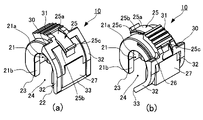
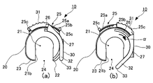
- FIG. 1 is a front perspective view of a fluid device connector according to an embodiment of the present invention, in which (a) shows an open state and (b) shows a closed state.
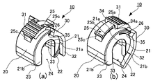
- FIG. 2 is a rear side perspective view of the coupler, in which (a) shows an open state and (b) shows a closed state.
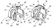
- FIG. 3 is a perspective view of the front side of the coupler as seen from below, where (a) shows an open state and (b) shows a closed state.
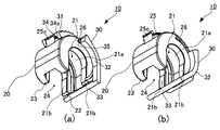
- FIG. 4 is a perspective view of the rear side of the coupler as seen from below, in which (a) shows an open state and (b) shows a closed state.
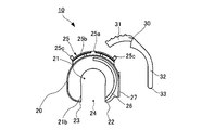
- FIG. 5 is a left side view of the coupler, where (a) shows the open state and (b) shows the closed state.
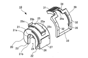
- FIG. 6 is a front side perspective view showing an exploded connector.
- FIG. 7 is a rear side perspective view showing an exploded connector.
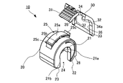
- FIG. 8 is an exploded view of the coupler, and is a perspective view of the front side viewed from below.
- FIG. 9 is an exploded view of the coupler, and is a perspective view of the rear side viewed from below.
- FIG. 10 is a left side view showing an exploded connector.
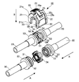
- 11A and 11B are explanatory diagrams showing a procedure for connecting the fluid device and the connector.
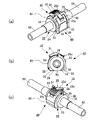
- FIG. 12 shows a state in which the connector is attached to the connecting portion of the fluid device, and is (a) a front perspective view, (b) a left side view, and (c) a rear perspective view.
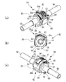
- FIG. 13 shows (a) a front perspective view, (b) a left side view, and (c) a rear perspective view in which the connector is attached to the connecting portion of the fluid device and the sealing piece is closed.
- a fluid device connector 10 and a fluid device connection structure 40 according to an embodiment of the present invention will be described below with reference to the drawings.
- FIGS. 6 to 10 are perspective views and the like showing the connector 10 in an exploded manner. 1 to 5, the open state in which the sealing piece 30 is retracted is shown as (a), and the closed state in which the sealing piece 30 protrudes is shown as (b).
- the connector 10 is composed of a connecting piece 20 having an arcuately curved recess 21 and a sealing piece 30 attached to the connecting piece 20 so as to be retractable.
- the sealing piece 30 is slidably attached to the connecting piece 20, for example.
- the connecting piece 20 and the sealing piece 30 can be made of a material such as a fluororesin material that is excellent in thermal meltability, corrosion resistance, chemical resistance stability, and the like.
- Tetrafluoroethylene-perfluoroalkyl vinyl ether copolymer (PFA) is suitable as this type of fluororesin material, and polyvinylidene fluoride (PVDF), tetrafluoroethylene-hexafluoropropylene copolymer (FEP), Examples include tetrafluoroethylene-hexafluoropropylene-vinylidene fluoride terpolymer.
- PVDF polyvinylidene fluoride
- FEP tetrafluoroethylene-hexafluoropropylene-vinylidene fluoride terpolymer
- PPS polyphenylene sulfide
- the connecting piece 20 has a recess 21 at least partially curved in an arc shape.
- the connecting piece 20 has a first edge 22 and a second edge 23 that are continuous with the recess 21 , and a radially open opening is provided between the first edge 22 and the second edge 23 .
- a portion 24 is formed.
- connection piece 20 may be formed in a substantially C-shaped configuration in which the bottom side of the recess 21 is curved in an arc shape (semicircle), and the first end edge 22 and the second end edge 23 extend substantially parallel from the tip of the arc. can.
- the inner surface shape of the recess 21 itself of the connecting piece 20 is substantially U-shaped.
- the recess 21 of the connecting piece 20 includes a groove 21a and groove walls 21b, 21b projecting inward from both sides of the groove 21a.
- the groove 21a has an arc shape in which a connecting portion 55 (FIGS. 11 to 13 described later) of the fluid device 50 described later is fitted.
- the width is substantially the same as the width of the connecting portion 55 (the overlapping thickness of the two joints 51, 51 and the seal member 54).
- the groove walls 21b, 21b have an arc shape into which the later-described body portion 52 following the connection portion 55 is fitted, and have substantially the same radius of curvature as the outer diameter of the body portion 52.
- the connecting piece 20 sandwiches the joint 51 of the connecting portion 55 between the groove walls 21b, 21b, and holds the fluid devices 50, 50 in a connected state.
- the connecting piece 20 is formed with an opening 24 into which the connecting portion 55 of the fluid device 50 is inserted.
- the opening width of the opening 24 is determined according to the connecting portion 55 .
- the distance between the grooves 21a of the first edge 22 and the second edge 23 is the outer diameter of the sealing member 54 (FIG. 11) of the connecting portion 55
- the curvature radius of the groove wall 21b is It is substantially the same as the diameter of the portion 52 .
- a mechanism is provided on the outer peripheral surface and/or the side surface of the connecting piece 20 to support the sealing piece 30 so that it can appear and retract.
- the haunting form can be, for example, a slide.
- a guide rail 25 is provided on the bent portion of the outer circumference of the connecting piece 20.
- the guide rail 25 has a rail surface 25a curved along the circumferential direction of the connecting piece 20 with a predetermined width.
- the guide rail 25 has a rail groove 25b formed between the outer peripheral surface of the connecting piece 20 and the rail surface 25a.
- the rail surface 25a is formed with regulating projections 25c, 25c for regulating the sliding range of the sealing piece 30 at the proximal end and the distal end in the circumferential direction.
- a guide groove 26 for slidably guiding the sealing piece 30 as a sliding structure is formed in an arc shape from near the top of the bent portion of the connecting piece 20 toward the first edge 22. recessed.
- the radius of curvature of the guide groove 26 is smaller than the radius of curvature of the guide rail 25 .
- This configuration implements a locking mechanism for the connecting piece 20 and the sealing piece 30, which will be described later.
- the connecting piece 20 can be provided with a nameplate 27 on the front side, on which the product number, product name, size, etc. are attached.
- the sealing piece 30 attached to the connecting piece 20 described above is arranged so as to be retractable from the first end edge 22 side of the connecting piece 20 toward the second end edge 23 side, and the connecting piece 20 is connected to the connection portion of the fluid device 50 . A part or the whole of the opening part 24 is blocked in a state of being attached to the connector 55 to prevent the coupler 10 from coming off.
- the sealing piece 30 has an operation part 31 on the base end side, which is operated by the user with a thumb or the like.
- the operating portion 31 can be provided with unevenness for slip prevention.
- the sealing piece 30 is formed in a frame shape.
- the sealing piece 30 has left and right frames 32 , 32 provided at wide intervals from the operation part 31 toward the tip side, and the tips of the left and right frames 32 , 32 are connected by a tip frame 33 . ing.
- the tip frame 33 of the sealing piece 30 is flush with or flush with the first edge 22 when the sealing piece 30 is most retracted, as shown in FIGS.
- the left and right frames 32, 32 are formed to have lengths that reach or approach the second edge 23 side from the center.
- the left and right frames 32, 32 protrude outside the connecting piece 20 as shown in FIG.
- the sealing piece 30 is projected, the protruding left and right frames 32, 32 move along the outer peripheral surface of the flange 53 of the connecting portion 55 and hit the flange 53 as shown in FIG. He is trying to prevent the coupler 10 from coming off by coming into contact with it.
- a slide structure that slidably engages with the guide rail 25 of the connecting piece 20 is provided on the back side of the operation portion 31 .
- the illustrated slide structure is a slide groove 34 that fits into the guide rail 25.
- the slide groove 34 has a groove bottom that slides on the rail surface 25a of the guide rail 25, and has an inward direction that fits into the rail groove 25b of the guide rail 25. It has a slide projection 34a projecting outward.
- sealing piece 30 is formed so that the inner surfaces of the left and right frames 32 , 32 sandwich the side surface of the connecting piece 20 .
- a slide strip 35 to be fitted is projected.
- the connector 10 is constructed by attaching the sealing piece 30 to the connecting piece 20 .
- the sealing piece 30 fits the slide groove 34 into the guide rail 25 of the connecting piece 20 . Since the guide rail 25 has the rail groove 25b on the inner peripheral side of the rail surface 25a, the sealing piece 30 contacts the rail surface 25a with the groove bottom of the slide groove 34, and the slide protrusion 34a is in contact with the rail groove. 25b to hold the guide rail 25. Thereby, the sealing piece 30 can be attached to the connecting piece 20 in a slidable and non-dropping manner.
- the slide strip 35 of the sealing piece 30 is fitted into the guide groove 26 of the connecting piece 20 .
- the sealing piece 30 has a slide structure in which a slide groove 34 fits into the guide rail 25 of the connecting piece 20 on the base end side where the operation part 31 is provided, and the slide strips 35 of the left and right frames 32, 32 are connected on the tip end side. It has a sliding structure that fits into the guide groove 26 of the piece 20 . With these two sliding structures, the sealing piece 30 as a whole is slidably attached without being separated from the connecting piece 20 in the radial direction.
- the fluid device 50 connected by the connector 10 configured as described above has a joint 51 formed at the tip thereof, and has a form such as a pipe through which a fluid can flow.
- a connecting portion 55 is formed by abutting them in the direction of arrow A in FIG.
- a flange 53 is formed at the rear portion of the joint 51 with a cylindrical body portion 52 interposed therebetween.
- the flange 53 is a member that is pressed by a jig (not shown) when the joints 51 and 51 are pressed against the seal member 54 .
- the configuration of the connecting portion 55 is an example, and other configurations may be used.
- the connector 10 since the connector 10 is in a state where it is difficult to move with respect to the connector piece 20 due to friction or the like when the sealing piece 30 is retracted, the connector 10 can be held with one hand without blocking the opening 24 . It is possible to grasp the fluid device 50 and bring it close to the connection portion 55 of the fluid device 50 . In particular, when the jig is operated with one hand to work while the flanges 53, 53 of the connecting portion 55 are pressed, the coupler 10 of the present invention, which can be grasped and mounted with one hand, is excellent in operability.
- connection portion 55 (the joint 51 and the seal member 54) is accommodated in the groove 21a of the connecting piece 20, and the joints 51, 51 on both sides are held between the inner surfaces of the groove walls 21b, 21b.
- the connecting portion 55 is non-separably connected by the connecting piece 20 .
- FIGS. 1 to 5B and 13 the user pushes the operating portion 31 of the sealing piece 30 with the thumb to project the sealing piece 30 into the opening 24.
- FIG. The sealing piece 30 slides relative to the connecting piece 20 in the direction indicated by the arrow ⁇ in FIGS. faces the opening 24 .
- the opening 24 is at least partially blocked by the sealing piece 30, as best shown in FIG. 13(b). Since the opening width of the opening 24 is smaller than the diameter of the connecting portion 55, the connecting tool 10 cannot fall off from the connecting portion 55, and the connecting structure 40 in which the fluid devices 50, 50 are connected to each other can be obtained. . 13, the sealing piece 30 closes the opening 24 so that the left and right frames 32, 32 slide along the outer peripheral surface of the flange 53 of the connecting portion 55 and press the flange 53. The configuration also prevents the coupler 10 from coming off.
- the sealing piece 30 is excellent in workability because it is only necessary to slide the operation part 31 with the thumb.
- the sealing piece 30 since the sealing piece 30 abuts against the restricting protrusion 25c of the guide rail 25 and the projecting position is restricted, the sealing piece 30 does not come off from the guide rail 25 when it is pushed.
- the guide groove 26 of the connecting piece 20 is provided on the inner diameter side of the connecting piece 20 with respect to the guide rail 25 . That is, the radius of curvature of the guide groove 26 is smaller than the radius of curvature of the rail surface 25a. For this reason, when the sealing piece 30 is slid toward the opening 24 side, the operation part 31 moves between the slide strip 35 that slides along the guide groove 26 and the slide groove 34 that slides along the rail surface 25 a of the guide rail 25 . will move on different radii of curvature.
- the slide strip 35 is pressed against the outer diameter side of the guide groove 26, the slide groove 34 is pressed against the rail surface 25a located on the inner diameter side, and the sealing piece 30 is positioned in a projecting state with respect to the connecting piece 20. It is possible to configure a locking mechanism that
- the sealing piece 30 Since the sealing piece 30 is positioned in a projecting state with respect to the connecting piece 20 by the locking mechanism described above, the sealing piece 30 does not retreat even if the fluid device 50 is subjected to vibration or the like, preventing the connecting member 10 from falling off. can be prevented.
- the sealing piece 30 slides along the outer peripheral surface of the flange 53 by pushing the operating portion 31 .
- the sealing piece 30 will remain closed even if the operation portion 31 is pushed.
- the inner surfaces of the left and right frames 32, 32 come into contact with the connecting portion 55, which is the outer peripheral surface of the flange 53 in this embodiment, and the sealing piece 30 is pushed out in the outer diameter direction.
- the slide strip 35 of the sealing piece 30 is pressed against the outer diameter side of the guide groove 26, the left and right frames 32, 32 are stretched, and the movement of the sealing piece 30 is prevented.
- the sealing piece 30 is configured to be able to appear and retract with respect to the opening 24 only when the connecting piece 20 is properly attached to the connecting portion 55 of the fluid device 50 . Therefore, if the sealing piece 30 can be slid, it also confirms that the coupler 10 is properly attached to the connecting portion 55 .
- the connector 10 of the present invention can be operated with one hand by providing the sealing piece 30 that can be retracted from the opening 24 of the connecting piece 20, and can achieve good workability even in a space-saving manner.
- the coupler 10 can hold the connecting part 55 in a sandwiched state without falling off from the connecting part 55, the sealing property is excellent, and leakage of fluid from the connecting part 55 can be prevented.
- the sealing piece 30 is pulled in the backward direction in the reverse order of the mounting procedure described above, the opening 24 of the connecting piece 20 is fully opened, and the connecting piece 20 is removed from the connecting portion 55. Take it.
- the shapes of the connecting piece 20 and the sealing piece 30 are not limited to the above embodiment.
- the sealing piece 30 is in the form of a frame in the embodiment, it may be in the form of an arc-shaped flat plate or the like.
- the sealing piece 30 protrudes most and does not reach the second edge 23 , but the sealing piece 30 is formed long in the circumferential direction so that the tip of the sealing piece 30 reaches the second edge 23 . It may be configured to reach the edge 23 .
- the tip of the sealing piece 30 is provided with a claw or a dent, while the second edge 23 is provided with a dent or claw that engages therewith. It can also be engaged and positioned to form a locking mechanism.
- Fluid device connector 20 Connection piece 21 Recess 22 First edge 23 Second edge 24 Opening 30 Sealing piece 40 Fluid device connection structure 50 Fluid device 55 Connection part
Landscapes
- Engineering & Computer Science (AREA)
- General Engineering & Computer Science (AREA)
- Mechanical Engineering (AREA)
- Quick-Acting Or Multi-Walled Pipe Joints (AREA)
- Flanged Joints, Insulating Joints, And Other Joints (AREA)
Abstract
Description
流体機器どうしの接続部を連結する流体機器連結具であって、
少なくとも一部が円弧状に湾曲した凹みと、前記凹みの内面に連続する第1端縁と第2端縁を有し、前記第1端縁と前記第2端縁との間に前記接続部が挿入可能な開口部が形成された連結片と、
前記第1端縁側から前記第2端縁側に向けて出没可能に配備され、前記第1端縁から突出した状態で前記開口部を塞ぐ封止片と、
を含む。
前記連結片は、前記凹みに前記継手及び前記シール部材が嵌まる溝が形成された構成にすることができる。
流体機器どうしの接続部に、上記構成の流体機器連結具を装着してなる。
20 連結片
21 凹み
22 第1端縁
23 第2端縁
24 開口部
30 封止片
40 流体機器連結構造
50 流体機器
55 接続部
Claims (8)
- 流体機器どうしの接続部を連結する流体機器連結具であって、
少なくとも一部が円弧状に湾曲した凹みと、前記凹みの内面に連続する第1端縁と第2端縁を有し、前記第1端縁と前記第2端縁との間に前記接続部が挿入可能な開口部が形成された連結片と、
前記第1端縁側から前記第2端縁側に向けて出没可能に配備され、前記第1端縁から突出した状態で前記開口部を塞ぐ封止片と、
を含む、流体機器連結具。 - 前記封止片は、前記連結片にスライド可能に配備される、
請求項1に記載の流体機器連結具。 - 前記連結片と前記封止片は、前記封止片を前記第1端縁側から突出した状態で前記連結片に対して位置決めするロック機構を有する、
請求項1又は請求項2に記載の流体機器連結具。 - 前記封止片は、前記第1端縁側から最も突出した状態で先端が前記第2端縁側に届く、
請求項1乃至請求項3の何れかに記載の流体機器連結具。 - 前記封止片は、前記第1端縁側から最も突出した状態で先端が前記第2端縁側に届かない、
請求項1乃至請求項3の何れかに記載の流体機器連結具。 - 前記流体機器は、先端に継手が形成されており、一対の前記流体機器を前記継手間に環状のシール部材を介在させた状態で突き合わせて前記接続部が構成され、
前記連結片は、前記凹みに前記継手及び前記シール部材が嵌まる溝が形成されている、
請求項1乃至請求項5の何れかに記載の流体機器連結具。 - 前記封止片は、前記連結片が、前記流体機器の前記接続部に正しく装着された状態で前記開口部に対して出没可能である、
請求項1乃至請求項6の何れかに記載の流体機器連結具。 - 流体機器どうしの接続部に、請求項1乃至請求項7の何れかに記載の流体機器連結具を装着してなる、
流体機器連結構造。
Priority Applications (3)
| Application Number | Priority Date | Filing Date | Title |
|---|---|---|---|
| CN202280036395.3A CN117355695A (zh) | 2021-06-17 | 2022-03-31 | 流体设备连结件及流体设备连结结构 |
| KR1020237042450A KR20240022478A (ko) | 2021-06-17 | 2022-03-31 | 유체 기기 연결구 및 유체 기기 연결 구조 |
| US18/563,553 US12474001B2 (en) | 2021-06-17 | 2022-03-31 | Fluid device coupler and fluid device coupling structure |
Applications Claiming Priority (2)
| Application Number | Priority Date | Filing Date | Title |
|---|---|---|---|
| JP2021100728A JP7431416B2 (ja) | 2021-06-17 | 2021-06-17 | 流体機器連結具及び流体機器連結構造 |
| JP2021-100728 | 2021-06-17 |
Publications (1)
| Publication Number | Publication Date |
|---|---|
| WO2022264658A1 true WO2022264658A1 (ja) | 2022-12-22 |
Family
ID=84527096
Family Applications (1)
| Application Number | Title | Priority Date | Filing Date |
|---|---|---|---|
| PCT/JP2022/016840 Ceased WO2022264658A1 (ja) | 2021-06-17 | 2022-03-31 | 流体機器連結具及び流体機器連結構造 |
Country Status (6)
| Country | Link |
|---|---|
| US (1) | US12474001B2 (ja) |
| JP (1) | JP7431416B2 (ja) |
| KR (1) | KR20240022478A (ja) |
| CN (1) | CN117355695A (ja) |
| TW (1) | TW202300805A (ja) |
| WO (1) | WO2022264658A1 (ja) |
Families Citing this family (2)
| Publication number | Priority date | Publication date | Assignee | Title |
|---|---|---|---|---|
| US11566738B2 (en) | 2020-08-27 | 2023-01-31 | Colder Products Company | Fluid couplings |
| USD1089566S1 (en) * | 2022-03-31 | 2025-08-19 | Nidec Corporation | Plug of pipe joint |
Citations (9)
| Publication number | Priority date | Publication date | Assignee | Title |
|---|---|---|---|---|
| JP2006242378A (ja) * | 2005-02-28 | 2006-09-14 | Illinois Tool Works Inc <Itw> | 外れ防止ラチェットクリップ |
| JP2009103303A (ja) * | 2007-10-05 | 2009-05-14 | Ckd Corp | 流体機器接続構造及び流体機器ユニット |
| JP2013540953A (ja) * | 2010-07-27 | 2013-11-07 | エタブリスマン カジョー | 第1チューブと第2チューブとを連結およびプレフィットするためのクランピングシステム |
| US20150008663A1 (en) * | 2013-07-03 | 2015-01-08 | Etablissements Caillau | Clamping device comprising a collar and a sleeve |
| JP2017190869A (ja) * | 2016-04-12 | 2017-10-19 | エタブリスマン・カイロウEtablissements Caillau | クランプカラーおよびスリーブを含むクランプデバイス |
| JP2018091482A (ja) * | 2016-12-01 | 2018-06-14 | Ckd株式会社 | 連結部材、流体機器接続治具及び流体機器接続構造 |
| JP3219049U (ja) * | 2018-09-14 | 2018-11-22 | 淀川ヒューテック株式会社 | 流量計付きチューブ |
| JP3226054U (ja) * | 2019-11-13 | 2020-04-23 | 陳▲シン▼航CHEN, Xinhang | 急速脱着型調節式ケーブルクランプ |
| CN210686525U (zh) * | 2019-10-31 | 2020-06-05 | 扬州市华凌电器设备有限公司 | 一种防脱落电气挂杆箱 |
Family Cites Families (10)
| Publication number | Priority date | Publication date | Assignee | Title |
|---|---|---|---|---|
| US5620210A (en) * | 1995-10-24 | 1997-04-15 | Stanley Aviation Corporation | Fluid conduit coupling |
| US5842450A (en) * | 1998-04-13 | 1998-12-01 | Ford Motor Company | Fuel regulator retaining clip |
| US7014225B1 (en) * | 2004-09-07 | 2006-03-21 | Viking Plastics, Inc. | Snap connector for the coupling of pipes |
| US8328458B2 (en) * | 2007-07-20 | 2012-12-11 | Twin Bay Medical, Inc. | Sanitary clamp |
| US8033579B2 (en) | 2007-10-05 | 2011-10-11 | Ckd Corporation | Fluid device connecting structure |
| WO2012122311A1 (en) * | 2011-03-07 | 2012-09-13 | Nordson Corporation | Clamp for sanitary fitting |
| JP5968617B2 (ja) * | 2011-12-13 | 2016-08-10 | 武蔵エンジニアリング株式会社 | 配管接続用クランプ |
| US11060637B2 (en) * | 2016-12-01 | 2021-07-13 | Ckd Corporation | Coupling member, fluid-device connecting jig, and fluid-device connecting structure |
| CN110735979B (zh) * | 2018-07-18 | 2022-12-09 | 淀川惠德株式会社 | 管道连结件的安装确认件 |
| JP7281362B2 (ja) | 2019-08-07 | 2023-05-25 | 日本ピラー工業株式会社 | 連結部材 |
-
2021
- 2021-06-17 JP JP2021100728A patent/JP7431416B2/ja active Active
-
2022
- 2022-03-31 WO PCT/JP2022/016840 patent/WO2022264658A1/ja not_active Ceased
- 2022-03-31 KR KR1020237042450A patent/KR20240022478A/ko active Pending
- 2022-03-31 US US18/563,553 patent/US12474001B2/en active Active
- 2022-03-31 CN CN202280036395.3A patent/CN117355695A/zh active Pending
- 2022-05-10 TW TW111117454A patent/TW202300805A/zh unknown
Patent Citations (9)
| Publication number | Priority date | Publication date | Assignee | Title |
|---|---|---|---|---|
| JP2006242378A (ja) * | 2005-02-28 | 2006-09-14 | Illinois Tool Works Inc <Itw> | 外れ防止ラチェットクリップ |
| JP2009103303A (ja) * | 2007-10-05 | 2009-05-14 | Ckd Corp | 流体機器接続構造及び流体機器ユニット |
| JP2013540953A (ja) * | 2010-07-27 | 2013-11-07 | エタブリスマン カジョー | 第1チューブと第2チューブとを連結およびプレフィットするためのクランピングシステム |
| US20150008663A1 (en) * | 2013-07-03 | 2015-01-08 | Etablissements Caillau | Clamping device comprising a collar and a sleeve |
| JP2017190869A (ja) * | 2016-04-12 | 2017-10-19 | エタブリスマン・カイロウEtablissements Caillau | クランプカラーおよびスリーブを含むクランプデバイス |
| JP2018091482A (ja) * | 2016-12-01 | 2018-06-14 | Ckd株式会社 | 連結部材、流体機器接続治具及び流体機器接続構造 |
| JP3219049U (ja) * | 2018-09-14 | 2018-11-22 | 淀川ヒューテック株式会社 | 流量計付きチューブ |
| CN210686525U (zh) * | 2019-10-31 | 2020-06-05 | 扬州市华凌电器设备有限公司 | 一种防脱落电气挂杆箱 |
| JP3226054U (ja) * | 2019-11-13 | 2020-04-23 | 陳▲シン▼航CHEN, Xinhang | 急速脱着型調節式ケーブルクランプ |
Also Published As
| Publication number | Publication date |
|---|---|
| CN117355695A (zh) | 2024-01-05 |
| US20240360927A1 (en) | 2024-10-31 |
| KR20240022478A (ko) | 2024-02-20 |
| JP7431416B2 (ja) | 2024-02-15 |
| US12474001B2 (en) | 2025-11-18 |
| TW202300805A (zh) | 2023-01-01 |
| JP2023000105A (ja) | 2023-01-04 |
Similar Documents
| Publication | Publication Date | Title |
|---|---|---|
| EP0853740B1 (en) | Improved fluid conduit coupling | |
| JP2023000105A (ja) | 流体機器連結具及び流体機器連結構造 | |
| JP6722607B2 (ja) | 配管継手 | |
| US11644138B2 (en) | Clamp | |
| JP2010082456A (ja) | ボールバルブ作動機構 | |
| US12007055B2 (en) | Compact fluid couplings | |
| US7547048B2 (en) | Fluid quick connector with integral pivotal retainer | |
| CN106090491A (zh) | 一种可拆式快插接头 | |
| US12624784B2 (en) | Fluid couplings with an in-line flow valve | |
| BR112019018478A2 (pt) | estrutura de acoplamento de eixo e aparelho de pressão de fluido | |
| US5865476A (en) | Locking mechanism for a coupling | |
| TWI706746B (zh) | 滑軌總成及其回歸裝置 | |
| US20190024833A1 (en) | Female Connector of a Plug-In Connector and Plug-In Connector | |
| CN209213270U (zh) | 快速连接器、滑动锁及套接部件 | |
| KR101485063B1 (ko) | 다중실링 버터플라이 밸브 | |
| CN106151738B (zh) | 一种可拆式快插接头的卡扣件 | |
| CN205877536U (zh) | 一种可拆式快插接头 | |
| JP2002005377A (ja) | 電子機器の冷却媒体用チューブのコネクター | |
| JP2011247347A (ja) | クイックファスナの外れ防止構造 | |
| JP2010096230A (ja) | 管継手 | |
| JP2604307Y2 (ja) | 管継手 | |
| CN120351224B (zh) | 一种拼接式管材连接配件 | |
| JP4842019B2 (ja) | 配管接続構造 | |
| JP3689366B2 (ja) | 管継手 | |
| CN116877813B (zh) | 一次性无菌断开器 |
Legal Events
| Date | Code | Title | Description |
|---|---|---|---|
| 121 | Ep: the epo has been informed by wipo that ep was designated in this application |
Ref document number: 22824653 Country of ref document: EP Kind code of ref document: A1 |
|
| WWE | Wipo information: entry into national phase |
Ref document number: 202280036395.3 Country of ref document: CN |
|
| NENP | Non-entry into the national phase |
Ref country code: DE |
|
| 122 | Ep: pct application non-entry in european phase |
Ref document number: 22824653 Country of ref document: EP Kind code of ref document: A1 |
|
| WWG | Wipo information: grant in national office |
Ref document number: 18563553 Country of ref document: US |