WO2022264532A1 - 濁度測定装置 - Google Patents
濁度測定装置 Download PDFInfo
- Publication number
- WO2022264532A1 WO2022264532A1 PCT/JP2022/007893 JP2022007893W WO2022264532A1 WO 2022264532 A1 WO2022264532 A1 WO 2022264532A1 JP 2022007893 W JP2022007893 W JP 2022007893W WO 2022264532 A1 WO2022264532 A1 WO 2022264532A1
- Authority
- WO
- WIPO (PCT)
- Prior art keywords
- measurement space
- window
- cleaning
- measuring device
- space
- Prior art date
- Legal status (The legal status is an assumption and is not a legal conclusion. Google has not performed a legal analysis and makes no representation as to the accuracy of the status listed.)
- Ceased
Links
Images



Classifications
-
- G—PHYSICS
- G01—MEASURING; TESTING
- G01N—INVESTIGATING OR ANALYSING MATERIALS BY DETERMINING THEIR CHEMICAL OR PHYSICAL PROPERTIES
- G01N21/00—Investigating or analysing materials by the use of optical means, i.e. using sub-millimetre waves, infrared, visible or ultraviolet light
- G01N21/01—Arrangements or apparatus for facilitating the optical investigation
- G01N21/15—Preventing contamination of the components of the optical system or obstruction of the light path
-
- G—PHYSICS
- G01—MEASURING; TESTING
- G01N—INVESTIGATING OR ANALYSING MATERIALS BY DETERMINING THEIR CHEMICAL OR PHYSICAL PROPERTIES
- G01N21/00—Investigating or analysing materials by the use of optical means, i.e. using sub-millimetre waves, infrared, visible or ultraviolet light
- G01N21/17—Systems in which incident light is modified in accordance with the properties of the material investigated
- G01N21/47—Scattering, i.e. diffuse reflection
- G01N21/49—Scattering, i.e. diffuse reflection within a body or fluid
-
- G—PHYSICS
- G01—MEASURING; TESTING
- G01N—INVESTIGATING OR ANALYSING MATERIALS BY DETERMINING THEIR CHEMICAL OR PHYSICAL PROPERTIES
- G01N21/00—Investigating or analysing materials by the use of optical means, i.e. using sub-millimetre waves, infrared, visible or ultraviolet light
- G01N21/75—Systems in which material is subjected to a chemical reaction, the progress or the result of the reaction being investigated
- G01N21/77—Systems in which material is subjected to a chemical reaction, the progress or the result of the reaction being investigated by observing the effect on a chemical indicator
- G01N21/82—Systems in which material is subjected to a chemical reaction, the progress or the result of the reaction being investigated by observing the effect on a chemical indicator producing a precipitate or turbidity
Definitions
- the present invention relates to a turbidity measuring device.
- a cleaning body for cleaning dirt adhering to the entrance window and the exit window is arranged inside the cell, and this cleaning body is driven to clean the entrance window and the exit window. It is considered to wash the
- the present invention has been made in view of the problems described above, and its main object is to provide a cleaning mechanism having a cleaning body for cleaning the entrance window and the exit window, while shortening the optical path length compared to conventional methods. is.
- the turbidity measuring device has a measurement space formed between a light source and a light detection unit to accommodate a liquid to be measured, an entrance window for guiding light from the light source to the measurement space, and the a cell having an exit window for guiding light from a measurement space to a photodetector; and a cleaning mechanism for cleaning the entrance window and the exit window, wherein the cleaning mechanism cleans the entrance window and the exit window.
- a driving unit provided outside the measurement space for retracting the cleaning body to the outside of the measurement space during measurement and for moving the cleaning body into the measurement space during cleaning. The body is rotated around a predetermined central axis by the driving section, and the central axis is provided outside the measurement space.
- a turbidity measuring device it is provided outside the measurement space, and the cleaning body is retracted to the outside of the measurement space during measurement, and the cleaning body is moved into the measurement space during cleaning. Since the drive section is provided and the central axis is provided outside the measurement space, the size of the measurement space can be reduced compared to the case where the cleaning body is always arranged inside the measurement space. can. As a result, the optical path length, which is the distance between the light source and the photodetector arranged across the measurement space, can be made shorter than before.
- the cell further has a communication space communicating with the measurement space, and the cleaning body is retracted into the communication space.
- the measurement space is formed of a first surface and a second surface facing each other, and a third surface connecting the first surface and the second surface, and the entrance window is formed in the first surface.
- a transmitted light exit window for measuring transmitted light may be formed on the second surface, and a scattered light exit window for measuring scattered light may be formed on the third surface.
- the driving section drives the cleaning body only once. can clean all these windows.
- the cell has an inlet for introducing a liquid to be measured therein and an outlet for leading the liquid to be measured from the inside, the inlet being arranged below the measurement space, and Assuming that the outlet is positioned above the measurement space, even if foreign matter or air bubbles are present in the liquid to be measured, the foreign matter or air bubbles remain in the measurement space. You can do as little as possible.
- the measurement space is opened vertically and that the third surface is provided parallel to the vertical direction.
- the communication space is formed so as to surround openings other than the first surface, the second surface and the third surface of the measurement space,
- the inlet and the outlet may be formed in the communication space.
- the window member forming the entrance window is integrally formed with a lens for condensing the light from the light source inside the cell, a separate member is provided between the light source and the entrance window. It takes less space than arranging lenses.
- the driving unit is provided outside the measurement space and retracts the cleaning body to the outside of the measurement space during measurement and moves the cleaning body into the measurement space during cleaning, Furthermore, since the central axis is provided outside the measurement space, the size of the measurement space can be reduced compared to the case where the cleaning body is always arranged inside the measurement space. As a result, the optical path length, which is the distance between the light source and the photodetector arranged across the measurement space, can be made shorter than before.
- FIG. 1 is a schematic diagram showing the overall structure of a water quality monitor for an exhaust gas purifier equipped with a turbidity measuring device according to one embodiment of the present invention; Schematic diagram showing the entire turbidity measuring device according to the present embodiment.
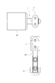
- FIG. 2 is a schematic diagram showing the structure around the cell of the turbidity measuring device according to the present embodiment.
- FIG. 2 is a schematic diagram showing the internal structure of the cell of the turbidity measuring device according to the present embodiment;
- FIG. 2 is a schematic diagram showing the internal structure of the cell of the turbidity measuring device according to the present embodiment;
- FIG. 1 is a schematic diagram showing the overall structure of a water quality monitor for an exhaust gas purifier equipped with a turbidity measuring device according to one embodiment of the present invention; Schematic diagram showing the entire turbidity measuring device according to the present embodiment.
- FIG. 2 is a schematic diagram showing the structure around the cell of the turbidity measuring device according to the present embodiment.
- FIG. 2 is a
- FIG. 2 is a schematic diagram showing the structure of a cleaning mechanism included in the turbidity measuring device according to the present embodiment
- FIG. 2 is a schematic diagram showing the structure of a cleaning mechanism included in the turbidity measuring device according to the present embodiment
- FIG. 2 is a schematic diagram showing the structure of a cleaning mechanism included in the turbidity measuring device according to the present embodiment
- the schematic diagram which shows the turbidity measuring device which concerns on other embodiment which concerns on this invention.
- the turbidity measuring device 100 for example, continuously measures and monitors the turbidity of wastewater discharged from homes, factories, ships, and the like. It is mounted on a monitor or the like.
- this exhaust gas purifier water quality monitor includes a channel through which waste water to be monitored flows; A PAH sensor that measures the concentration of polycyclic aromatic hydrocarbons (PAHs), a pH sensor that monitors the pH of waste water, a turbidity measuring device 100, and a display unit that displays the output values from these various sensors. Be prepared.
- the turbidity measuring apparatus 100 includes a turbidity meter 1 that measures the turbidity of wastewater to be measured, and based on the output signal output from the turbidity meter 1 It comprises a calculator 2 for calculating turbidity and an output unit 3 for outputting the turbidity calculated by the calculator 2 .
- the turbidity meter for example, as shown in FIG. , a transmitted light detector 13 for detecting transmitted light emitted from the light source 12 and transmitted through the waste water in the cell 11, and a scattered light detector 14 for detecting scattered light scattered by the waste water in the cell 11. , is provided.
- the light source unit 12 includes, for example, a light source 121 such as an LED, and an entrance window forming member 122 forming an entrance window 12a through which the light emitted from the light source 121 enters the cell 11.
- a light source 121 such as an LED
- an entrance window forming member 122 forming an entrance window 12a through which the light emitted from the light source 121 enters the cell 11.
- the optimal wavelength for measuring the scattered light and the transmitted light can be appropriately changed for each measurement object.
- the transmitted light detection unit 13 is arranged, for example, at a position facing the light source unit 12 with the cell 11 interposed therebetween. It includes a transmitted light exit window member 132 forming a transmitted light exit window 13a through which light from the measurement space is emitted toward the instrument.
- the scattered light detection unit 14 detects, for example, scattered light scattered at a predetermined angle with respect to the optical path of the light emitted from the light source unit 12.
- the scattered light detector 141 is a photodiode. and a scattered light exit window 14a forming a scattered light exit window 14a for emitting light from the inside of the cell 11 toward the scattered light detector 141, and the like.
- 90° is used as the predetermined angle.
- the calculation unit 2 calculates the transmitted turbidity based on the transmitted detection value output from the transmitted light detection unit 13 and the scattered turbidity based on the scattered detection value output from the scattered light detection unit 14 .
- the calculation unit 2 includes a digital circuit composed of a CPU, a memory, a communication port, etc., an analog circuit equipped with a buffer, an amplifier, etc., and an AD converter and a DA converter that mediate between these digital circuits and analog circuits. and the like.
- the information processing circuit functions as the calculating section 2 by the cooperation of the CPU and its peripheral devices according to the predetermined program stored in the memory.
- the output unit 3 outputs either the scattered turbidity and/or the transmitted turbidity calculated by the calculation unit 2.
- the scattered turbidity and/or the transmitted turbidity are displayed as numerical values, graphs, etc. This is the display.
- the display section is the display section of the water quality monitor for the exhaust gas purifier described above.
- a switching unit for switching the output value output from the output unit 3 between scattering turbidity and transmission turbidity may be further provided.
- the switching unit switches the output value output from the output unit 3 between scattering turbidity and transmission turbidity, for example, based on a switching index value that is a ratio of a scattering detection value and a transmission detection value.
- This switching section is realized by the information processing circuit described above, and functions as a switching section by the cooperation of the CPU and its peripheral devices in accordance with a predetermined program stored in the memory. You can make it work.
- the switching index value may be obtained, for example, based on the ratio of the scattering detection value to the transmission detection value (eg, scattering detection value/transmission detection value), and a predetermined threshold value is set for this switching index value.
- the switching unit determines that the switching index value exceeds the threshold for the output value output from the output unit 3, the output value is set as the transmission turbidity, and the switching index value is less than or equal to the threshold.
- the output value may be switched to the scattered turbidity.
- dark-colored wastewater containing colored contaminants such as black
- the higher the concentration of colored contaminants the worse the correlation between the detected value of scattered light measurement and the turbidity. Since accurate turbidity measurement becomes difficult, when turbidity exceeds a predetermined value (e.g. 40 degrees), it is recommended to adopt transmitted light measurement instead of scattered light measurement. is considered realistic.
- the turbidity measuring device 100 includes the cleaning mechanism 4 that cleans the inner surface of the cell 11 .
- the turbidity measuring apparatus 100 according to the present embodiment is also characterized by the shape of the cell 11, so the cell 11 will be explained first.
- the cell 11 of the turbidity measuring apparatus 100 according to the present embodiment is formed between the light source unit 12, the transmitted light detection unit 13, and the scattered light detection unit 14, and includes a measurement space 11a containing the liquid to be measured and the measurement space 11a. It has a communication space 11b that communicates with 11a.
- the measurement space 11 a has an incident surface 11 a 1 (also referred to as a first surface) on which light from the light source is incident, and light incident from the incident surface 11 a 1 and transmitted through the liquid to be measured is emitted toward the transmitted light detection unit 13 .
- a transmitted light exit surface 11a2 also referred to as a second surface
- a scattered light exit surface 11a3 third It is also called a surface.
- the entrance window 12a described above is formed on the entrance surface 11a1.
- the transmitted light exit surface 11a2 is formed with the transmitted light exit window 13a, and the scattered light exit surface 11a3 is formed with the scattered light exit window 14a.
- the entrance window forming member 122 forming the entrance window 12a is integrally formed with the lens so as to also function as a lens for condensing the light from the light source.
- part of the entrance window forming member 122 is a curved surface 122a that functions as a lens.
- the entrance window forming member 122 is made of brass or the like, which is screwed and fixed to the plate member 123 arranged around the light source 121 and the plate member 123, for example. It is arranged so as to be pressed against the pressing member 124 .
- the plate member 123 is fixed at three points to the substrate 121a to which the light source 121 is attached, so that the entrance window forming member 122 can be stably supported.
- the entrance surface 11a1 and the transmitted light exit surface 11a2 are arranged so as to face each other.
- the entrance surface 11a1 and the transmitted light exit surface 11a2 are provided so as to face each other in parallel.
- the scattered light detector 14 detects 90° scattered light, so the scattered light exit surface 11a3 is arranged perpendicular to the entrance surface 11a1 and the transmitted light exit surface 11a2. It is In this embodiment, the entrance surface 11a1, the transmitted light exit surface 11a2, and the scattered light exit surface 11a3 are arranged in parallel in the vertical direction, and the measurement space 11a is opened in the vertical direction.
- the measurement space 11a in this embodiment is formed only by the entrance surface 11a1, the transmitted light exit surface 11a2, and the scattered light exit surface 11a3, and the three sides other than those three surfaces are the openings 11c.
- the communication space 11b communicates with the measurement space 11a through the opening 11c, and is formed so as to surround the measurement space 11a.
- An inlet 11d for introducing the liquid to be measured into the cell 11 and an outlet 11e for leading the liquid to be measured from the inside of the cell 11 are formed in the communicating space 11b.
- the introduction port 11d is formed below the measurement space 11a in the vertical direction, and the outlet port 11e is formed above the introduction port 11d and the measurement space 11a.
- a projecting portion 111 is formed in which the inner surface of the cell 11 facing the inlet 11d protrudes toward the inlet 11d.
- the cleaning mechanism 4 cleans, for example, the entrance window 12a, the transmitted light exit window 13a, and the scattered light exit window 14a among the inner surfaces of the cell 11 described above. 12a, the transmitted light exit window 13a and the scattered light exit window 14a, and a cleaning unit 41 for wiping off stains adhering to the surfaces of these windows 13a and 14a, and a driving unit 42 for driving the cleaning unit 41.
- the cleaning unit 41 includes a cleaning body 411 such as a plate-shaped wiper made of resin such as nitrile rubber, and a holding part 412 that holds the cleaning body 411 .
- the shape of the cleaning body 411 is such that when the cleaning body 411 enters the measurement space 11a, the surfaces of the entrance window 12a, the transmitted light exit window 13a, and the scattered light exit window 14a are substantially aligned. It has a T-shaped shape projecting in three directions so that they can be brought into contact at the same time and washed at once.
- the holding part 412 is, for example, a member whose overall shape is a quadrangular prism, holding the cleaning body 411 so as to sandwich it from both sides and connecting it to the driving part 42 .
- the thickness and length of the holding part 412 are such that when the cleaning body 411 enters the measurement space 11a, the tip of the cleaning body 411 can contact the surfaces of the entrance window 12a, the transmitted light exit window 13a, and the scattered light exit window 14a. It is like this.
- the drive unit 42 is provided outside the measurement space 11a, as shown in FIGS. It drives so that it may enter the inside of 11a.
- the driving section 42 includes a rotating section 421 that rotates the cleaning section 41 around a predetermined central axis X, a motor section 422 that applies a driving force to the rotating section 421, and the motor section 422. It has a drive control unit (not shown) that controls the operation.
- the function as the drive control unit may be performed by the information processing circuit described above.
- the predetermined central axis X is provided outside the measurement space 11a.
- the central axis X may be set so as not to intersect the measurement space 11a. It is provided to rotate the cleaning section 41 in a direction parallel to the incident surface 11a1 and the transmitted light emitting surface 11a2. More specifically, the central axis X according to the present embodiment is a direction perpendicular to the vertical direction, perpendicular to the incident surface 11a1 and the transmitted light emitting surface 11a2, and perpendicular to the scattered light emitting surface 11a3. are set so that they are parallel to each other.
- the time of measurement means that the transmitted light detection unit 13 or the scattered light detection unit 14 is detecting the transmission detection value or the scattering detection value used by the calculation unit 2 to calculate the turbidity.
- the time of washing means the time when the washing body 411 is entering the measurement space 11a.
- the time of measurement and the time of cleaning are preferably set as separate periods, but they may partially overlap.
- the rotating part 421 rotates the cleaning part 41 in a certain direction so as to wipe the surfaces of the incident window 12a, the transmitted light emitting window 13a, and the scattered light emitting window 14a from the lower side to the upper side. is preferred.
- the cleaning unit 41 can be detached from the drive unit 42 and replaced in case the cleaning unit 411 deteriorates.
- the rotating portion 421 is provided with a joint J for attaching the holding portion 412 holding the cleaning body 411.
- the joint J is provided with a mark for confirming the attachment method of the holding portion 412 by touching.
- Mounting guides such as one or more protrusions, are formed.
- the mounting guide may include a joint J having one projection T formed on one surface thereof. By predetermining the position of the projection T and the mounting direction of the holding portion 412, the user can confirm the position of the projection T even if the interior of the cell 11 is dark and difficult to see.
- the retainer 412 can be attached in any desired orientation.
- the holding portion 412 side is formed with a recess C for accommodating the projection T described above. You may make it generate a click feeling at the time of attaching.
- Examples of procedures and methods for cleaning the inner surface of the cell 11 by the cleaning mechanism 4 using the turbidity measuring device 100 configured as described above include the following. 3, 5, and 7, the drive unit 42 of the cleaning mechanism 4 moves the cleaning body 411 of the cleaning unit 41 into the measurement space 11a. It is designed to stop at the position on the opposite side.
- the rotating portion 421 is rotated by the torque given by the motor portion 422 so that the cleaning body 411 enters the inside of the measurement space 11a at the earliest possible timing, and the cleaning portion 41 is moved to the central axis X described above. , enter the measurement space 11a from the lower part of the opening 11c of the measurement space 11a, and exit from the upper part of the opening 11c of the measurement space 11a to the communication space 11b, for example, by one rotation.
- the tip of the cleaning body 411 arranged at the tip of the cleaning part 41 that has entered the measurement space 11a comes into contact with the entrance window 12a, the transmitted light exit window 13a, and the scattered light exit window 14a. It is designed to wipe off dirt.
- the measurement space 11a and the communication space 11b surrounding the measurement space 11a are provided inside the cell 11, and the entire cleaning mechanism 4 is placed in the communication space 11b during measurement. Therefore, compared to the conventional turbidity measuring device in which only the measurement space 11a is provided inside the cell, and part of the cleaning unit and the driving unit are arranged therein, the measurement space 11a can be reduced in size. As a result, the length of the optical path formed between the entrance window 12a and the exit windows 13a, 14a can be shortened as much as possible while providing the cleaning mechanism 4 for cleaning the entrance window 12a and the exit windows 13a, 14a.
- the cleaning body 411 is shaped to contact all of the entrance window 12a, the transmitted light exit window 13a, and the scattered light exit window 14a. Therefore, the entrance window 12a, the transmitted light exit window 13a, and the scattered light exit window 14a can be cleaned in as short a time as possible. Therefore, even if the liquid to be measured that continuously flows into the cell 11 is continuously measured, the measurement is stopped in order to clean the entrance window 12a, the transmitted light exit window 13a, and the scattered light exit window 14a. It is possible to continue measurements without cleaning these windows between measurements.
- the effect of this embodiment is particularly remarkable when the interval between measurements must be within several tens of seconds, such as when measuring the turbidity of waste water from a ship.
- An inlet 11d for introducing the liquid to be measured into the cell 11 and an outlet 11e for leading the liquid to be measured from the cell 11 are formed in the communicating space 11b. Since the outlet 11e is formed above the measurement space 11a, even if foreign matter is mixed in the liquid to be measured, it is possible to prevent the foreign matter from remaining in the measurement space 11a as much as possible. Further, even if air bubbles are mixed in the liquid to be measured, the air bubbles are less likely to remain in the measurement space 11a, so that the measurement accuracy can be further improved.
- the measurement space 11a is opened vertically, and the scattered light emitting surface 142 is also arranged parallel to the vertical direction, so that foreign substances and air bubbles are less likely to stay in the measurement space 11a. .
- the liquid to be measured that has flowed into the cell 11 from the introducing port 11d collides with the projecting portion 111 and becomes a turbulent flow. stagnation of the liquid to be measured inside can be suppressed as much as possible.
- the central axis X when rotating the cleaning unit 41 is perpendicular to the incident surface 11a1 and the transmitted light emitting surface 11a2 forming the measurement space 11a, that is, between the incident surface 11a1 and the transmitted light emitting surface 11a2. Since it is provided parallel to the formed optical path of the transmitted light and the scattered light exit surface 11a3, the shape of the cleaning portion 41 can be made as simple as possible.
- the drive unit 42 rotates the cleaning unit 41 from the bottom to the top of the measurement space 11a, dirt can be discharged toward the outlet 11e formed above the measurement space 11a.
- the cleaning body 411 is positioned on the opposite side of the communication space 11b to the side where the measurement space 11a is formed. Therefore, the flow of the liquid to be measured flowing into the measurement space 11a is not hindered, which is preferable.
- the entrance window forming member 122 that forms the entrance window 12a is integrally formed with the lens, the space required is smaller than when a separate lens is arranged between the light source 121 and the entrance window forming member 122. can be omitted.
- the plate member 123 for fixing the entrance window forming member 122 is fixed at three points, and the lens retainer 124 made of brass is provided. be able to.
- the invention is not limited to the embodiments described above.
- the shape of the cleaning body is not limited to those described above.
- the cleaning body is not limited to being in contact with the incident window, the transmitted light exit window and the scattered light exit window almost at the same time.
- the entrance window, the transmitted light exit window, and the scattered light exit window may be cleaned separately.
- the cleaning mechanism does not have to have a rotating part.
- it may have a slide part and slide the cleaning part along a rail or the like provided in advance to send it into the measurement space.
- the scattered light detector may detect scattered light other than the 90-degree scattered light.
- the measurement space only needs to have an opening through which the cleaning body enters the measurement space.
- the central shaft described above is provided so that the rotating part rotates the cleaning part so that the cleaning part enters the measuring space and cleans the incident window, the transmitted light exit window and/or the scattered light exit window.
- the central axis is aligned with the opening formed in the measurement space. You may provide diagonally with respect to. Needless to say, even if the central axis is set at an angle other than the angle shown in FIG. 9, the effects of the present invention can be similarly obtained.
- the central axis may intersect the inside of the measurement space.
- a turbidity measuring device having a shorter optical path length than the conventional one while providing a cleaning mechanism having a cleaning body for cleaning the entrance window and the exit window.
Landscapes
- Physics & Mathematics (AREA)
- Chemical & Material Sciences (AREA)
- General Health & Medical Sciences (AREA)
- Health & Medical Sciences (AREA)
- Life Sciences & Earth Sciences (AREA)
- Analytical Chemistry (AREA)
- Biochemistry (AREA)
- General Physics & Mathematics (AREA)
- Immunology (AREA)
- Pathology (AREA)
- Chemical Kinetics & Catalysis (AREA)
- Plasma & Fusion (AREA)
- Engineering & Computer Science (AREA)
- Optical Measuring Cells (AREA)
Priority Applications (1)
| Application Number | Priority Date | Filing Date | Title |
|---|---|---|---|
| JP2023529518A JPWO2022264532A1 (https=) | 2021-06-17 | 2022-02-25 |
Applications Claiming Priority (2)
| Application Number | Priority Date | Filing Date | Title |
|---|---|---|---|
| JP2021-101222 | 2021-06-17 | ||
| JP2021101222 | 2021-06-17 |
Publications (1)
| Publication Number | Publication Date |
|---|---|
| WO2022264532A1 true WO2022264532A1 (ja) | 2022-12-22 |
Family
ID=84526129
Family Applications (1)
| Application Number | Title | Priority Date | Filing Date |
|---|---|---|---|
| PCT/JP2022/007893 Ceased WO2022264532A1 (ja) | 2021-06-17 | 2022-02-25 | 濁度測定装置 |
Country Status (2)
| Country | Link |
|---|---|
| JP (1) | JPWO2022264532A1 (https=) |
| WO (1) | WO2022264532A1 (https=) |
Citations (5)
| Publication number | Priority date | Publication date | Assignee | Title |
|---|---|---|---|---|
| JPS4726360B1 (https=) * | 1968-01-22 | 1972-07-15 | ||
| JPS55141054U (https=) * | 1979-03-30 | 1980-10-08 | ||
| JPS56154646A (en) * | 1980-04-30 | 1981-11-30 | Yamatake Honeywell Co Ltd | Method and device of automatic washing control of optical turbidity measuring apparatus |
| JP2010060364A (ja) * | 2008-09-02 | 2010-03-18 | Horiba Ltd | 試料測定装置 |
| JP2014081280A (ja) * | 2012-10-16 | 2014-05-08 | Horiba Advanced Techno Co Ltd | 色度計 |
-
2022
- 2022-02-25 JP JP2023529518A patent/JPWO2022264532A1/ja active Pending
- 2022-02-25 WO PCT/JP2022/007893 patent/WO2022264532A1/ja not_active Ceased
Patent Citations (5)
| Publication number | Priority date | Publication date | Assignee | Title |
|---|---|---|---|---|
| JPS4726360B1 (https=) * | 1968-01-22 | 1972-07-15 | ||
| JPS55141054U (https=) * | 1979-03-30 | 1980-10-08 | ||
| JPS56154646A (en) * | 1980-04-30 | 1981-11-30 | Yamatake Honeywell Co Ltd | Method and device of automatic washing control of optical turbidity measuring apparatus |
| JP2010060364A (ja) * | 2008-09-02 | 2010-03-18 | Horiba Ltd | 試料測定装置 |
| JP2014081280A (ja) * | 2012-10-16 | 2014-05-08 | Horiba Advanced Techno Co Ltd | 色度計 |
Also Published As
| Publication number | Publication date |
|---|---|
| JPWO2022264532A1 (https=) | 2022-12-22 |
Similar Documents
| Publication | Publication Date | Title |
|---|---|---|
| CN102445437B (zh) | 一种浊度测量方法及装置 | |
| US7469601B2 (en) | Flow meter using digital signals | |
| US7593107B2 (en) | Method and system for diffusion attenuated total reflection based concentration sensing | |
| US8902427B2 (en) | System for measuring properties of test samples in fluid | |
| KR20190037035A (ko) | 큐벳의 자동세정이 가능한 흡광도 측정장치 | |
| WO2022264532A1 (ja) | 濁度測定装置 | |
| WO2010035612A1 (ja) | 液体濃度計 | |
| US20040100630A1 (en) | Particle size distribution analyzer | |
| JP2008191119A (ja) | 流体試料用フローセル | |
| CN108426836A (zh) | 水质监测装置 | |
| JP7559061B2 (ja) | 光学測定装置及び水質分析システム | |
| JP4284077B2 (ja) | 水質計 | |
| JPH01320449A (ja) | 光学測定器 | |
| US20230063177A1 (en) | Refractive-index concentration sensor | |
| JP2020165852A (ja) | 光学分析装置 | |
| CN210604381U (zh) | 细菌浊度仪 | |
| JPH11118715A (ja) | 水質計および水質測定方法 | |
| KR100414446B1 (ko) | 부유물농도측정장치 | |
| KR101420181B1 (ko) | 오염 모니터링 광센서 및 이를 이용한 수질오염 측정장치 | |
| US20250020577A1 (en) | Measurement instrument, measurement device, measurement system, and measurement method | |
| JP2013088302A (ja) | 検出器及び水質測定装置 | |
| JPS6033391Y2 (ja) | 油分濃度計のワイパ装置 | |
| JP4671485B2 (ja) | フローセル装置 | |
| KR200263024Y1 (ko) | 부유물농도측정장치 | |
| JP2561971Y2 (ja) | 水質チェッカー |
Legal Events
| Date | Code | Title | Description |
|---|---|---|---|
| 121 | Ep: the epo has been informed by wipo that ep was designated in this application |
Ref document number: 22824532 Country of ref document: EP Kind code of ref document: A1 |
|
| WWE | Wipo information: entry into national phase |
Ref document number: 2023529518 Country of ref document: JP |
|
| NENP | Non-entry into the national phase |
Ref country code: DE |
|
| 122 | Ep: pct application non-entry in european phase |
Ref document number: 22824532 Country of ref document: EP Kind code of ref document: A1 |