WO2022264532A1 - 濁度測定装置 - Google Patents
濁度測定装置 Download PDFInfo
- Publication number
- WO2022264532A1 WO2022264532A1 PCT/JP2022/007893 JP2022007893W WO2022264532A1 WO 2022264532 A1 WO2022264532 A1 WO 2022264532A1 JP 2022007893 W JP2022007893 W JP 2022007893W WO 2022264532 A1 WO2022264532 A1 WO 2022264532A1
- Authority
- WO
- WIPO (PCT)
- Prior art keywords
- measurement space
- window
- cleaning
- measuring device
- space
- Prior art date
Links
- 238000004140 cleaning Methods 0.000 claims abstract description 98
- 239000007788 liquid Substances 0.000 claims abstract description 32
- 238000001514 detection method Methods 0.000 claims abstract description 28
- 238000005259 measurement Methods 0.000 claims description 107
- 238000004891 communication Methods 0.000 claims description 17
- 239000002351 wastewater Substances 0.000 claims description 11
- 230000003287 optical effect Effects 0.000 abstract description 10
- 238000010586 diagram Methods 0.000 description 9
- 230000005540 biological transmission Effects 0.000 description 8
- 230000006870 function Effects 0.000 description 5
- 239000000356 contaminant Substances 0.000 description 3
- 230000010365 information processing Effects 0.000 description 3
- 238000000034 method Methods 0.000 description 3
- 238000005406 washing Methods 0.000 description 3
- XLYOFNOQVPJJNP-UHFFFAOYSA-N water Substances O XLYOFNOQVPJJNP-UHFFFAOYSA-N 0.000 description 3
- 229910001369 Brass Inorganic materials 0.000 description 2
- 239000010951 brass Substances 0.000 description 2
- 230000000694 effects Effects 0.000 description 2
- 230000002093 peripheral effect Effects 0.000 description 2
- 125000005575 polycyclic aromatic hydrocarbon group Chemical group 0.000 description 2
- 239000000758 substrate Substances 0.000 description 2
- 229920000459 Nitrile rubber Polymers 0.000 description 1
- 238000007796 conventional method Methods 0.000 description 1
- 238000012986 modification Methods 0.000 description 1
- 230000004048 modification Effects 0.000 description 1
- 238000003825 pressing Methods 0.000 description 1
- 239000011347 resin Substances 0.000 description 1
- 229920005989 resin Polymers 0.000 description 1
- 238000004904 shortening Methods 0.000 description 1
- 239000000126 substance Substances 0.000 description 1
Images


Classifications
-
- G—PHYSICS
- G01—MEASURING; TESTING
- G01N—INVESTIGATING OR ANALYSING MATERIALS BY DETERMINING THEIR CHEMICAL OR PHYSICAL PROPERTIES
- G01N21/00—Investigating or analysing materials by the use of optical means, i.e. using sub-millimetre waves, infrared, visible or ultraviolet light
- G01N21/01—Arrangements or apparatus for facilitating the optical investigation
- G01N21/15—Preventing contamination of the components of the optical system or obstruction of the light path
-
- G—PHYSICS
- G01—MEASURING; TESTING
- G01N—INVESTIGATING OR ANALYSING MATERIALS BY DETERMINING THEIR CHEMICAL OR PHYSICAL PROPERTIES
- G01N21/00—Investigating or analysing materials by the use of optical means, i.e. using sub-millimetre waves, infrared, visible or ultraviolet light
- G01N21/17—Systems in which incident light is modified in accordance with the properties of the material investigated
- G01N21/47—Scattering, i.e. diffuse reflection
- G01N21/49—Scattering, i.e. diffuse reflection within a body or fluid
-
- G—PHYSICS
- G01—MEASURING; TESTING
- G01N—INVESTIGATING OR ANALYSING MATERIALS BY DETERMINING THEIR CHEMICAL OR PHYSICAL PROPERTIES
- G01N21/00—Investigating or analysing materials by the use of optical means, i.e. using sub-millimetre waves, infrared, visible or ultraviolet light
- G01N21/75—Systems in which material is subjected to a chemical reaction, the progress or the result of the reaction being investigated
- G01N21/77—Systems in which material is subjected to a chemical reaction, the progress or the result of the reaction being investigated by observing the effect on a chemical indicator
- G01N21/82—Systems in which material is subjected to a chemical reaction, the progress or the result of the reaction being investigated by observing the effect on a chemical indicator producing a precipitate or turbidity
Definitions
- the present invention relates to a turbidity measuring device.
- a cleaning body for cleaning dirt adhering to the entrance window and the exit window is arranged inside the cell, and this cleaning body is driven to clean the entrance window and the exit window. It is considered to wash the
- the present invention has been made in view of the problems described above, and its main object is to provide a cleaning mechanism having a cleaning body for cleaning the entrance window and the exit window, while shortening the optical path length compared to conventional methods. is.
- the turbidity measuring device has a measurement space formed between a light source and a light detection unit to accommodate a liquid to be measured, an entrance window for guiding light from the light source to the measurement space, and the a cell having an exit window for guiding light from a measurement space to a photodetector; and a cleaning mechanism for cleaning the entrance window and the exit window, wherein the cleaning mechanism cleans the entrance window and the exit window.
- a driving unit provided outside the measurement space for retracting the cleaning body to the outside of the measurement space during measurement and for moving the cleaning body into the measurement space during cleaning. The body is rotated around a predetermined central axis by the driving section, and the central axis is provided outside the measurement space.
- a turbidity measuring device it is provided outside the measurement space, and the cleaning body is retracted to the outside of the measurement space during measurement, and the cleaning body is moved into the measurement space during cleaning. Since the drive section is provided and the central axis is provided outside the measurement space, the size of the measurement space can be reduced compared to the case where the cleaning body is always arranged inside the measurement space. can. As a result, the optical path length, which is the distance between the light source and the photodetector arranged across the measurement space, can be made shorter than before.
- the cell further has a communication space communicating with the measurement space, and the cleaning body is retracted into the communication space.
- the measurement space is formed of a first surface and a second surface facing each other, and a third surface connecting the first surface and the second surface, and the entrance window is formed in the first surface.
- a transmitted light exit window for measuring transmitted light may be formed on the second surface, and a scattered light exit window for measuring scattered light may be formed on the third surface.
- the driving section drives the cleaning body only once. can clean all these windows.
- the cell has an inlet for introducing a liquid to be measured therein and an outlet for leading the liquid to be measured from the inside, the inlet being arranged below the measurement space, and Assuming that the outlet is positioned above the measurement space, even if foreign matter or air bubbles are present in the liquid to be measured, the foreign matter or air bubbles remain in the measurement space. You can do as little as possible.
- the measurement space is opened vertically and that the third surface is provided parallel to the vertical direction.
- the communication space is formed so as to surround openings other than the first surface, the second surface and the third surface of the measurement space,
- the inlet and the outlet may be formed in the communication space.
- the window member forming the entrance window is integrally formed with a lens for condensing the light from the light source inside the cell, a separate member is provided between the light source and the entrance window. It takes less space than arranging lenses.
- the driving unit is provided outside the measurement space and retracts the cleaning body to the outside of the measurement space during measurement and moves the cleaning body into the measurement space during cleaning, Furthermore, since the central axis is provided outside the measurement space, the size of the measurement space can be reduced compared to the case where the cleaning body is always arranged inside the measurement space. As a result, the optical path length, which is the distance between the light source and the photodetector arranged across the measurement space, can be made shorter than before.
- FIG. 1 is a schematic diagram showing the overall structure of a water quality monitor for an exhaust gas purifier equipped with a turbidity measuring device according to one embodiment of the present invention; Schematic diagram showing the entire turbidity measuring device according to the present embodiment.
- FIG. 2 is a schematic diagram showing the structure around the cell of the turbidity measuring device according to the present embodiment.
- FIG. 2 is a schematic diagram showing the internal structure of the cell of the turbidity measuring device according to the present embodiment;
- FIG. 2 is a schematic diagram showing the internal structure of the cell of the turbidity measuring device according to the present embodiment;
- FIG. 1 is a schematic diagram showing the overall structure of a water quality monitor for an exhaust gas purifier equipped with a turbidity measuring device according to one embodiment of the present invention; Schematic diagram showing the entire turbidity measuring device according to the present embodiment.
- FIG. 2 is a schematic diagram showing the structure around the cell of the turbidity measuring device according to the present embodiment.
- FIG. 2 is a
- FIG. 2 is a schematic diagram showing the structure of a cleaning mechanism included in the turbidity measuring device according to the present embodiment
- FIG. 2 is a schematic diagram showing the structure of a cleaning mechanism included in the turbidity measuring device according to the present embodiment
- FIG. 2 is a schematic diagram showing the structure of a cleaning mechanism included in the turbidity measuring device according to the present embodiment
- the schematic diagram which shows the turbidity measuring device which concerns on other embodiment which concerns on this invention.
- the turbidity measuring device 100 for example, continuously measures and monitors the turbidity of wastewater discharged from homes, factories, ships, and the like. It is mounted on a monitor or the like.
- this exhaust gas purifier water quality monitor includes a channel through which waste water to be monitored flows; A PAH sensor that measures the concentration of polycyclic aromatic hydrocarbons (PAHs), a pH sensor that monitors the pH of waste water, a turbidity measuring device 100, and a display unit that displays the output values from these various sensors. Be prepared.
- the turbidity measuring apparatus 100 includes a turbidity meter 1 that measures the turbidity of wastewater to be measured, and based on the output signal output from the turbidity meter 1 It comprises a calculator 2 for calculating turbidity and an output unit 3 for outputting the turbidity calculated by the calculator 2 .
- the turbidity meter for example, as shown in FIG. , a transmitted light detector 13 for detecting transmitted light emitted from the light source 12 and transmitted through the waste water in the cell 11, and a scattered light detector 14 for detecting scattered light scattered by the waste water in the cell 11. , is provided.
- the light source unit 12 includes, for example, a light source 121 such as an LED, and an entrance window forming member 122 forming an entrance window 12a through which the light emitted from the light source 121 enters the cell 11.
- a light source 121 such as an LED
- an entrance window forming member 122 forming an entrance window 12a through which the light emitted from the light source 121 enters the cell 11.
- the optimal wavelength for measuring the scattered light and the transmitted light can be appropriately changed for each measurement object.
- the transmitted light detection unit 13 is arranged, for example, at a position facing the light source unit 12 with the cell 11 interposed therebetween. It includes a transmitted light exit window member 132 forming a transmitted light exit window 13a through which light from the measurement space is emitted toward the instrument.
- the scattered light detection unit 14 detects, for example, scattered light scattered at a predetermined angle with respect to the optical path of the light emitted from the light source unit 12.
- the scattered light detector 141 is a photodiode. and a scattered light exit window 14a forming a scattered light exit window 14a for emitting light from the inside of the cell 11 toward the scattered light detector 141, and the like.
- 90° is used as the predetermined angle.
- the calculation unit 2 calculates the transmitted turbidity based on the transmitted detection value output from the transmitted light detection unit 13 and the scattered turbidity based on the scattered detection value output from the scattered light detection unit 14 .
- the calculation unit 2 includes a digital circuit composed of a CPU, a memory, a communication port, etc., an analog circuit equipped with a buffer, an amplifier, etc., and an AD converter and a DA converter that mediate between these digital circuits and analog circuits. and the like.
- the information processing circuit functions as the calculating section 2 by the cooperation of the CPU and its peripheral devices according to the predetermined program stored in the memory.
- the output unit 3 outputs either the scattered turbidity and/or the transmitted turbidity calculated by the calculation unit 2.
- the scattered turbidity and/or the transmitted turbidity are displayed as numerical values, graphs, etc. This is the display.
- the display section is the display section of the water quality monitor for the exhaust gas purifier described above.
- a switching unit for switching the output value output from the output unit 3 between scattering turbidity and transmission turbidity may be further provided.
- the switching unit switches the output value output from the output unit 3 between scattering turbidity and transmission turbidity, for example, based on a switching index value that is a ratio of a scattering detection value and a transmission detection value.
- This switching section is realized by the information processing circuit described above, and functions as a switching section by the cooperation of the CPU and its peripheral devices in accordance with a predetermined program stored in the memory. You can make it work.
- the switching index value may be obtained, for example, based on the ratio of the scattering detection value to the transmission detection value (eg, scattering detection value/transmission detection value), and a predetermined threshold value is set for this switching index value.
- the switching unit determines that the switching index value exceeds the threshold for the output value output from the output unit 3, the output value is set as the transmission turbidity, and the switching index value is less than or equal to the threshold.
- the output value may be switched to the scattered turbidity.
- dark-colored wastewater containing colored contaminants such as black
- the higher the concentration of colored contaminants the worse the correlation between the detected value of scattered light measurement and the turbidity. Since accurate turbidity measurement becomes difficult, when turbidity exceeds a predetermined value (e.g. 40 degrees), it is recommended to adopt transmitted light measurement instead of scattered light measurement. is considered realistic.
- the turbidity measuring device 100 includes the cleaning mechanism 4 that cleans the inner surface of the cell 11 .
- the turbidity measuring apparatus 100 according to the present embodiment is also characterized by the shape of the cell 11, so the cell 11 will be explained first.
- the cell 11 of the turbidity measuring apparatus 100 according to the present embodiment is formed between the light source unit 12, the transmitted light detection unit 13, and the scattered light detection unit 14, and includes a measurement space 11a containing the liquid to be measured and the measurement space 11a. It has a communication space 11b that communicates with 11a.
- the measurement space 11 a has an incident surface 11 a 1 (also referred to as a first surface) on which light from the light source is incident, and light incident from the incident surface 11 a 1 and transmitted through the liquid to be measured is emitted toward the transmitted light detection unit 13 .
- a transmitted light exit surface 11a2 also referred to as a second surface
- a scattered light exit surface 11a3 third It is also called a surface.
- the entrance window 12a described above is formed on the entrance surface 11a1.
- the transmitted light exit surface 11a2 is formed with the transmitted light exit window 13a, and the scattered light exit surface 11a3 is formed with the scattered light exit window 14a.
- the entrance window forming member 122 forming the entrance window 12a is integrally formed with the lens so as to also function as a lens for condensing the light from the light source.
- part of the entrance window forming member 122 is a curved surface 122a that functions as a lens.
- the entrance window forming member 122 is made of brass or the like, which is screwed and fixed to the plate member 123 arranged around the light source 121 and the plate member 123, for example. It is arranged so as to be pressed against the pressing member 124 .
- the plate member 123 is fixed at three points to the substrate 121a to which the light source 121 is attached, so that the entrance window forming member 122 can be stably supported.
- the entrance surface 11a1 and the transmitted light exit surface 11a2 are arranged so as to face each other.
- the entrance surface 11a1 and the transmitted light exit surface 11a2 are provided so as to face each other in parallel.
- the scattered light detector 14 detects 90° scattered light, so the scattered light exit surface 11a3 is arranged perpendicular to the entrance surface 11a1 and the transmitted light exit surface 11a2. It is In this embodiment, the entrance surface 11a1, the transmitted light exit surface 11a2, and the scattered light exit surface 11a3 are arranged in parallel in the vertical direction, and the measurement space 11a is opened in the vertical direction.
- the measurement space 11a in this embodiment is formed only by the entrance surface 11a1, the transmitted light exit surface 11a2, and the scattered light exit surface 11a3, and the three sides other than those three surfaces are the openings 11c.
- the communication space 11b communicates with the measurement space 11a through the opening 11c, and is formed so as to surround the measurement space 11a.
- An inlet 11d for introducing the liquid to be measured into the cell 11 and an outlet 11e for leading the liquid to be measured from the inside of the cell 11 are formed in the communicating space 11b.
- the introduction port 11d is formed below the measurement space 11a in the vertical direction, and the outlet port 11e is formed above the introduction port 11d and the measurement space 11a.
- a projecting portion 111 is formed in which the inner surface of the cell 11 facing the inlet 11d protrudes toward the inlet 11d.
- the cleaning mechanism 4 cleans, for example, the entrance window 12a, the transmitted light exit window 13a, and the scattered light exit window 14a among the inner surfaces of the cell 11 described above. 12a, the transmitted light exit window 13a and the scattered light exit window 14a, and a cleaning unit 41 for wiping off stains adhering to the surfaces of these windows 13a and 14a, and a driving unit 42 for driving the cleaning unit 41.
- the cleaning unit 41 includes a cleaning body 411 such as a plate-shaped wiper made of resin such as nitrile rubber, and a holding part 412 that holds the cleaning body 411 .
- the shape of the cleaning body 411 is such that when the cleaning body 411 enters the measurement space 11a, the surfaces of the entrance window 12a, the transmitted light exit window 13a, and the scattered light exit window 14a are substantially aligned. It has a T-shaped shape projecting in three directions so that they can be brought into contact at the same time and washed at once.
- the holding part 412 is, for example, a member whose overall shape is a quadrangular prism, holding the cleaning body 411 so as to sandwich it from both sides and connecting it to the driving part 42 .
- the thickness and length of the holding part 412 are such that when the cleaning body 411 enters the measurement space 11a, the tip of the cleaning body 411 can contact the surfaces of the entrance window 12a, the transmitted light exit window 13a, and the scattered light exit window 14a. It is like this.
- the drive unit 42 is provided outside the measurement space 11a, as shown in FIGS. It drives so that it may enter the inside of 11a.
- the driving section 42 includes a rotating section 421 that rotates the cleaning section 41 around a predetermined central axis X, a motor section 422 that applies a driving force to the rotating section 421, and the motor section 422. It has a drive control unit (not shown) that controls the operation.
- the function as the drive control unit may be performed by the information processing circuit described above.
- the predetermined central axis X is provided outside the measurement space 11a.
- the central axis X may be set so as not to intersect the measurement space 11a. It is provided to rotate the cleaning section 41 in a direction parallel to the incident surface 11a1 and the transmitted light emitting surface 11a2. More specifically, the central axis X according to the present embodiment is a direction perpendicular to the vertical direction, perpendicular to the incident surface 11a1 and the transmitted light emitting surface 11a2, and perpendicular to the scattered light emitting surface 11a3. are set so that they are parallel to each other.
- the time of measurement means that the transmitted light detection unit 13 or the scattered light detection unit 14 is detecting the transmission detection value or the scattering detection value used by the calculation unit 2 to calculate the turbidity.
- the time of washing means the time when the washing body 411 is entering the measurement space 11a.
- the time of measurement and the time of cleaning are preferably set as separate periods, but they may partially overlap.
- the rotating part 421 rotates the cleaning part 41 in a certain direction so as to wipe the surfaces of the incident window 12a, the transmitted light emitting window 13a, and the scattered light emitting window 14a from the lower side to the upper side. is preferred.
- the cleaning unit 41 can be detached from the drive unit 42 and replaced in case the cleaning unit 411 deteriorates.
- the rotating portion 421 is provided with a joint J for attaching the holding portion 412 holding the cleaning body 411.
- the joint J is provided with a mark for confirming the attachment method of the holding portion 412 by touching.
- Mounting guides such as one or more protrusions, are formed.
- the mounting guide may include a joint J having one projection T formed on one surface thereof. By predetermining the position of the projection T and the mounting direction of the holding portion 412, the user can confirm the position of the projection T even if the interior of the cell 11 is dark and difficult to see.
- the retainer 412 can be attached in any desired orientation.
- the holding portion 412 side is formed with a recess C for accommodating the projection T described above. You may make it generate a click feeling at the time of attaching.
- Examples of procedures and methods for cleaning the inner surface of the cell 11 by the cleaning mechanism 4 using the turbidity measuring device 100 configured as described above include the following. 3, 5, and 7, the drive unit 42 of the cleaning mechanism 4 moves the cleaning body 411 of the cleaning unit 41 into the measurement space 11a. It is designed to stop at the position on the opposite side.
- the rotating portion 421 is rotated by the torque given by the motor portion 422 so that the cleaning body 411 enters the inside of the measurement space 11a at the earliest possible timing, and the cleaning portion 41 is moved to the central axis X described above. , enter the measurement space 11a from the lower part of the opening 11c of the measurement space 11a, and exit from the upper part of the opening 11c of the measurement space 11a to the communication space 11b, for example, by one rotation.
- the tip of the cleaning body 411 arranged at the tip of the cleaning part 41 that has entered the measurement space 11a comes into contact with the entrance window 12a, the transmitted light exit window 13a, and the scattered light exit window 14a. It is designed to wipe off dirt.
- the measurement space 11a and the communication space 11b surrounding the measurement space 11a are provided inside the cell 11, and the entire cleaning mechanism 4 is placed in the communication space 11b during measurement. Therefore, compared to the conventional turbidity measuring device in which only the measurement space 11a is provided inside the cell, and part of the cleaning unit and the driving unit are arranged therein, the measurement space 11a can be reduced in size. As a result, the length of the optical path formed between the entrance window 12a and the exit windows 13a, 14a can be shortened as much as possible while providing the cleaning mechanism 4 for cleaning the entrance window 12a and the exit windows 13a, 14a.
- the cleaning body 411 is shaped to contact all of the entrance window 12a, the transmitted light exit window 13a, and the scattered light exit window 14a. Therefore, the entrance window 12a, the transmitted light exit window 13a, and the scattered light exit window 14a can be cleaned in as short a time as possible. Therefore, even if the liquid to be measured that continuously flows into the cell 11 is continuously measured, the measurement is stopped in order to clean the entrance window 12a, the transmitted light exit window 13a, and the scattered light exit window 14a. It is possible to continue measurements without cleaning these windows between measurements.
- the effect of this embodiment is particularly remarkable when the interval between measurements must be within several tens of seconds, such as when measuring the turbidity of waste water from a ship.
- An inlet 11d for introducing the liquid to be measured into the cell 11 and an outlet 11e for leading the liquid to be measured from the cell 11 are formed in the communicating space 11b. Since the outlet 11e is formed above the measurement space 11a, even if foreign matter is mixed in the liquid to be measured, it is possible to prevent the foreign matter from remaining in the measurement space 11a as much as possible. Further, even if air bubbles are mixed in the liquid to be measured, the air bubbles are less likely to remain in the measurement space 11a, so that the measurement accuracy can be further improved.
- the measurement space 11a is opened vertically, and the scattered light emitting surface 142 is also arranged parallel to the vertical direction, so that foreign substances and air bubbles are less likely to stay in the measurement space 11a. .
- the liquid to be measured that has flowed into the cell 11 from the introducing port 11d collides with the projecting portion 111 and becomes a turbulent flow. stagnation of the liquid to be measured inside can be suppressed as much as possible.
- the central axis X when rotating the cleaning unit 41 is perpendicular to the incident surface 11a1 and the transmitted light emitting surface 11a2 forming the measurement space 11a, that is, between the incident surface 11a1 and the transmitted light emitting surface 11a2. Since it is provided parallel to the formed optical path of the transmitted light and the scattered light exit surface 11a3, the shape of the cleaning portion 41 can be made as simple as possible.
- the drive unit 42 rotates the cleaning unit 41 from the bottom to the top of the measurement space 11a, dirt can be discharged toward the outlet 11e formed above the measurement space 11a.
- the cleaning body 411 is positioned on the opposite side of the communication space 11b to the side where the measurement space 11a is formed. Therefore, the flow of the liquid to be measured flowing into the measurement space 11a is not hindered, which is preferable.
- the entrance window forming member 122 that forms the entrance window 12a is integrally formed with the lens, the space required is smaller than when a separate lens is arranged between the light source 121 and the entrance window forming member 122. can be omitted.
- the plate member 123 for fixing the entrance window forming member 122 is fixed at three points, and the lens retainer 124 made of brass is provided. be able to.
- the invention is not limited to the embodiments described above.
- the shape of the cleaning body is not limited to those described above.
- the cleaning body is not limited to being in contact with the incident window, the transmitted light exit window and the scattered light exit window almost at the same time.
- the entrance window, the transmitted light exit window, and the scattered light exit window may be cleaned separately.
- the cleaning mechanism does not have to have a rotating part.
- it may have a slide part and slide the cleaning part along a rail or the like provided in advance to send it into the measurement space.
- the scattered light detector may detect scattered light other than the 90-degree scattered light.
- the measurement space only needs to have an opening through which the cleaning body enters the measurement space.
- the central shaft described above is provided so that the rotating part rotates the cleaning part so that the cleaning part enters the measuring space and cleans the incident window, the transmitted light exit window and/or the scattered light exit window.
- the central axis is aligned with the opening formed in the measurement space. You may provide diagonally with respect to. Needless to say, even if the central axis is set at an angle other than the angle shown in FIG. 9, the effects of the present invention can be similarly obtained.
- the central axis may intersect the inside of the measurement space.
- a turbidity measuring device having a shorter optical path length than the conventional one while providing a cleaning mechanism having a cleaning body for cleaning the entrance window and the exit window.
Landscapes
- Physics & Mathematics (AREA)
- Chemical & Material Sciences (AREA)
- General Health & Medical Sciences (AREA)
- Health & Medical Sciences (AREA)
- Life Sciences & Earth Sciences (AREA)
- Analytical Chemistry (AREA)
- Biochemistry (AREA)
- General Physics & Mathematics (AREA)
- Immunology (AREA)
- Pathology (AREA)
- Chemical Kinetics & Catalysis (AREA)
- Plasma & Fusion (AREA)
- Engineering & Computer Science (AREA)
- Optical Measuring Cells (AREA)
Abstract
入射窓及び出射窓を洗浄する洗浄体を備える洗浄機構を設けながらも、光路長を従来よりも短くする。光源と光検出部との間に形成されて測定対象液を収容する測定空間を有し、光源からの光を前記測定空間に導く入射窓及び前記測定空間からの光を光検出部に導く出射窓を有するセルと、前記入射窓及び前記出射窓を洗浄する洗浄機構とを備え、前記洗浄機構は、前記入射窓及び前記出射窓を洗浄する洗浄体と、前記測定空間の外部に設けられ、測定時において前記洗浄体を前記測定空間の外部に退避させるとともに、洗浄時に前記洗浄体を前記測定空間内に移動させる駆動部とを有することを特徴とする濁度測定装置とした。
Description
本発明は、濁度測定装置に関するものである。
種々の成分を含む測定対象液を測定する場合には、測定対象液を収容し濁度を測定する測定空間を形成しているセルの内面に汚れが付着してしまうことがある。このような場合に、セルの内面のうち、光源からの光が入射する入射窓や測定対象液を透過した又は測定対象液によって散乱された光が検出器に向けて出射する出射窓に汚れが付着してしまうと濁度測定に影響が出る恐れがある。
そこで、先行文献1~3に示すように、入射窓及び出射窓に付着した汚れを洗浄する洗浄体をセルの内部に配置しておいて、この洗浄体を駆動させて、入射窓及び出射窓を洗浄することが考えられている。
ところで、排水などの夾雑物が多く含まれている測定対象液を測定する場合には、測定対象液中を光が透過しにくくなるので、透過光による濁度測定の測定精度をより向上させるためには、光源から光検出器までの光路長を短くすることが求められる。
しかしながら、従来のように洗浄体を測定空間の内部に配置する場合には、測定空間内に洗浄体を配置するために、光路長を短くすることが難しいという問題がある。
本発明は前述した課題に鑑みてなされたものであり、入射窓及び出射窓を洗浄する洗浄体を備える洗浄機構を設けながらも、光路長を従来よりも短くすることを主な目的とするものである。
すなわち、本発明に係る濁度測定装置は、光源と光検出部との間に形成されて測定対象液を収容する測定空間を有し、光源からの光を前記測定空間に導く入射窓及び前記測定空間からの光を光検出部に導く出射窓を有するセルと、前記入射窓及び前記出射窓を洗浄する洗浄機構とを備え、前記洗浄機構は、前記入射窓及び前記出射窓を洗浄する洗浄体と、前記測定空間の外部に設けられ、測定時において前記洗浄体を前記測定空間の外部に退避させるとともに、洗浄時に前記洗浄体を前記測定空間内に移動させる駆動部とを備え、前記洗浄体が、前記駆動部によって所定の中心軸周りに回転されるものであり、前記中心軸が、前記測定空間の外部に設けられているものであることを特徴とするものである。
このような濁度測定装置によれば、前記測定空間の外部に設けられ、測定時において前記洗浄体を前記測定空間の外部に退避させるとともに、洗浄時に前記洗浄体を前記測定空間内に移動させる駆動部を備え、さらに前記中心軸が、前記測定空間の外部に設けられているので、前記洗浄体を常に前記測定空間の内部に配置する場合に比べて測定空間の大きさを小さくすることができる。その結果、測定空間を挟んで配置される光源と光検出器との間の距離である光路長を従来よりも短くすることができる。
本発明の具体的な実施態様としては、前記セルが、前記測定空間に連通する連通空間をさらに有し、前記洗浄体が前記連通空間に退避されるものを挙げることができる。
前記測定空間は、互いに対向する第1面及び第2面と、当該第1面及び第2面を接続する第3面とから形成されており、前記第1面に前記入射窓が形成されており、前記第2面に透過光を測定するための透過光出射窓が形成されており、前記第3面に散乱光を測定するための散乱光出射窓が形成されているものとしても良い。
前記洗浄体が、前記測定空間に入り込んだ状態で、前記入射窓、前記透過光出射窓及び前記散乱光出射窓に接触するものであれば、前記駆動部が前記洗浄体を一度駆動させただけで、これらすべての窓を洗浄することができる。
前記セルが、内部に測定対象液を導入する導入口と、内部から測定対象液を導出する導出口とを有し、前記導入口が、前記測定空間よりも下側に配置されており、前記導出口が前記測定空間よりも上側に位置するように配置されているものとすれば、測定対象液中に異物や気泡などが存在する場合であっても、前記測定空間に異物や気泡が滞留することをできるだけ抑えることができる。
測定対象液中に含まれる異物や気泡の影響をより低減するためには、前記測定空間が上下に開口するとともに、前記第3面が前記上下方向に対して平行に設けられていることが好ましい。
本発明の具体的な実施態様としては、前記連通空間が、前記測定空間の前記第1面、前記第2面及び前記第3面以外の開口部を取り囲むように形成されているものであり、前記導入口及び前記導出口が前記連通空間に形成されているものを挙げることができる。
前記入射窓を形成している窓部材が、前記光源からの光を前記セルの内部に集光させるレンズと一体に形成されているものであれば、光源と入射窓との間に別体のレンズを配置するよりも省スペースである。
本発明によれば、前記測定空間の外部に設けられ、測定時において前記洗浄体を前記測定空間の外部に退避させるとともに、洗浄時に前記洗浄体を前記測定空間内に移動させる駆動部を備え、さらに前記中心軸が、前記測定空間の外部に設けられているので、前記洗浄体を常に前記測定空間の内部に配置する場合に比べて測定空間の大きさを小さくすることができる。その結果、測定空間を挟んで配置される光源と光検出器との間の距離である光路長を従来よりも短くすることができる。
100 ・・・濁度測定装置
1 ・・・濁度計
11 ・・・セル
11a ・・・測定空間
11a1・・・入射面(第1面)
11a2・・・透過光出射面(第2面)
11a3・・・散乱光出射面(第3面)
11b ・・・連通空間
11d ・・・導入口
11e ・・・導出口
121 ・・・光源
12a ・・・入射窓
122 ・・・入射窓形成部材
13 ・・・透過光検出部
13a ・・・透過光出射窓
14 ・・・散乱光検出部
14a ・・・散乱光出射窓
4 ・・・洗浄機構
41 ・・・洗浄部
411 ・・・洗浄体
42 ・・・駆動部
X ・・・中心軸
1 ・・・濁度計
11 ・・・セル
11a ・・・測定空間
11a1・・・入射面(第1面)
11a2・・・透過光出射面(第2面)
11a3・・・散乱光出射面(第3面)
11b ・・・連通空間
11d ・・・導入口
11e ・・・導出口
121 ・・・光源
12a ・・・入射窓
122 ・・・入射窓形成部材
13 ・・・透過光検出部
13a ・・・透過光出射窓
14 ・・・散乱光検出部
14a ・・・散乱光出射窓
4 ・・・洗浄機構
41 ・・・洗浄部
411 ・・・洗浄体
42 ・・・駆動部
X ・・・中心軸
以下に、本発明の一実施形態について、図面を用いて説明する。
本実施形態に係る濁度測定装置100は、例えば、家庭や工場、船舶などから排出される排水の濁度を連続的に測定して監視するものであり、例えば、船舶の排ガス浄化装置用水質モニタ等に搭載されるものである。
この排ガス浄化装置用水質モニタは、例えば、図1に示すように、モニタ対象である排水が流れる流路と、この流路上に配置され排水の脱泡処理を行う連続脱泡装置と、排水中の多環芳香族炭化水素(PAHs)の濃度を測定するPAHセンサと、排水のpHをモニタするpHセンサと、濁度測定装置100と、これら各種センサからの出力値を表示する表示部とを備えるものである。
本実施形態に係る濁度測定装置100は、例えば、家庭や工場、船舶などから排出される排水の濁度を連続的に測定して監視するものであり、例えば、船舶の排ガス浄化装置用水質モニタ等に搭載されるものである。
この排ガス浄化装置用水質モニタは、例えば、図1に示すように、モニタ対象である排水が流れる流路と、この流路上に配置され排水の脱泡処理を行う連続脱泡装置と、排水中の多環芳香族炭化水素(PAHs)の濃度を測定するPAHセンサと、排水のpHをモニタするpHセンサと、濁度測定装置100と、これら各種センサからの出力値を表示する表示部とを備えるものである。
本実施形態に係る濁度測定装置100は、図2に示すように、測定対象である排水の濁度を測定する濁度計1と、該濁度計1から出力される出力信号に基づいて濁度を算出する算出部2と、該算出部2によって算出された濁度を出力する出力部3とを備えるものである。
濁度計1は、例えば図3に示すように、排水が流れる流路に接続されて排水を内部に収容するセル11と、該セル11内の排水に対して光を出射する光源部12と、該光源部12から出射されてセル11内の排水中を透過した透過光を検出する透過光検出部13と、セル11内の排水によって散乱された散乱光を検出する散乱光検出部14と、を備えるものである。
光源部12は、例えば、LED等の光源121と、この光源121から出射される光をセル11内に入射させる入射窓12aを形成する入射窓形成部材122等を具備するものである。光源121から出射される光の波長は、散乱光及び透過光を測定するために最適な波長を測定対象毎に適宜変更することが可能である。
透過光検出部13は、例えば、前記セル11を挟んで光源部12に対向する位置に配置されたものであり、例えば、透過光用検出器131であるフォトダイオードと、セル11の内部から検出器に向けて測定空間からの光を出射させる透過光出射窓13aを形成する透過光出射窓部材132などを具備するものである。
散乱光検出部14は、例えば、光源部12から出射された光の光路に対して所定の角度に散乱された散乱光を検出するものであり、例えば、散乱光用検出器141であるフォトダイオードと、セル11の内部から散乱光用検出器141に向けて光を出射する散乱光出射窓14aを形成する散乱光出射窓14aなどを具備するものである。本実施形態では、前記所定の角度として、90°を採用している。
算出部2は、透過光検出部13から出力される透過検出値に基づく透過濁度及び散乱光検出部14から出力される散乱検出値に基づく散乱濁度を算出するものである。具体的にこの算出部2は、CPUやメモリ、通信ポートなどから構成されたデジタル回路と、バッファーや増幅器などを具備するアナログ回路と、これらデジタル回路とアナログ回路とを仲立ちするADコンバータ、DAコンバータなどを具備した情報処理回路である。そして、前記メモリに記憶させた所定のプログラムにしたがってCPUやその周辺機器が協働することにより、この情報処理回路が算出部2としての機能を発揮する。
出力部3は、算出部2によって算出された散乱濁度及び/又は透過濁度のいずれかを出力するものであり、例えば、散乱濁度及び/又は透過濁度を数値やグラフ等として表示する表示部である。この表示部は、本実施形態では、前述した排ガス浄化装置用水質モニタの表示部のことである。
出力部3から出力される出力値を散乱濁度と透過濁度との間で切り替える切替部をさらに備えるものとしても良い。
出力部3から出力される出力値を散乱濁度と透過濁度との間で切り替える切替部をさらに備えるものとしても良い。
切替部は、例えば、散乱検出値と透過検出値との比である切替指標値に基づいて、出力部3から出力される出力値を散乱濁度と透過濁度との間で切り替えるものである。この切替部は、前述した情報処理回路がその機能を発揮するものであり、前記メモリに記憶させた所定のプログラムにしたがってCPUやその周辺機器が協働することにより、切替部としての機能を発揮するようにしても良い。
前記切替指標値は、例えば、散乱検出値と透過検出値との比(例えば、散乱検出値/透過検出値)に基づいて求められるものとしてよく、この切替指標値について、所定の閾値を設定しておき、切替部が、出力部3から出力される出力値について、切替指標値が閾値を超えていると判断した場合には出力値を透過濁度とし、また切替指標値が閾値以下であると判断した場合には出力値を散乱濁度とするように切り替えるものであっても良い。
例えば、黒色等の有色夾雑物を含有する色の濃い排水(以下、濃色排水ともいう。)については、有色夾雑物の濃度が高くなると散乱光測定の検出値と濁度との相関が悪くなり、正確な濁度測定が困難になることから、濁度が所定の値(例えば40度)を超えた場合には、散乱光測定ではなく、透過光を測定する透過光測定を採用することが現実的であると考えられるからである。
しかして、本実施形態に係る濁度測定装置100は、前記セル11の内面を洗浄する洗浄機構4を備えるものである。
本実施形態に係る濁度測定装置100は、図3及び図4に示すように、セル11の形状にも特徴を有するものであるので、まずはセル11について説明することとする。
本実施形態に係る濁度測定装置100のセル11は、光源部12と透過光検出部13と散乱光検出部14との間に形成され、測定対象液を収容する測定空間11aとこの測定空間11aに連通する連通空間11bとを有するものである。
本実施形態に係る濁度測定装置100は、図3及び図4に示すように、セル11の形状にも特徴を有するものであるので、まずはセル11について説明することとする。
本実施形態に係る濁度測定装置100のセル11は、光源部12と透過光検出部13と散乱光検出部14との間に形成され、測定対象液を収容する測定空間11aとこの測定空間11aに連通する連通空間11bとを有するものである。
測定空間11aは、光源からの光が入射する入射面11a1(第1面ともいう。)と、入射面11a1から入射して測定対象液を透過した光が透過光検出部13に向けて出射される透過光出射面11a2(第2面ともいう。)と、入射面11a1から入射して測定対象液によって散乱された光が散乱光検出部14に向けて出射する散乱光出射面11a3(第3面ともいう。)とによって形成された空間である。
入射面11a1には、前述した入射窓12aが形成されている。
また、透過光出射面11a2には前述した透過光出射窓13aが、散乱光出射面11a3には前述した散乱光出射窓14aが形成されている。
また、透過光出射面11a2には前述した透過光出射窓13aが、散乱光出射面11a3には前述した散乱光出射窓14aが形成されている。
本実施形態では、入射窓12aを形成する入射窓形成部材122が光源からの光を集光するレンズとしての機能を兼ねるようにレンズと一体形成してある。具体的には、図4のAに示すように、入射窓形成部材122の一部がレンズとしての機能を果たす曲面122aになっている。この入射窓形成部材122は、図4のAに示すように、光源121の周囲に配置されたプレート部材123とこのプレート部材123に対して、例えば、螺合して固定された真鍮等からなる押さえ部材124とに対して押し付けられるように配置されている。プレート部材123は、このプレート部材123を光源121が取り付けられている基板121aに対して3点止めすることによって安定して入射窓形成部材122を支持することができるようにしてある。
入射面11a1と透過光出射面11a2とは互いに対向するように配置されている。本実施形態では、入射面11a1と透過光出射面11a2とは互いに平行になるように対向して設けられている。
また、散乱光出射面11a3は、本実施形態では、散乱光検出部14が90°散乱光を検出するものであるので、入射面11a1及び透過光出射面11a2に対して垂直になるように配置されている。
本実施形態においては、入射面11a1、透過光出射面11a2及び散乱光出射面11a3は、上下方向に平行に配置されており、測定空間11aは上下方向に開口するものとなっている。
本実施形態においては、入射面11a1、透過光出射面11a2及び散乱光出射面11a3は、上下方向に平行に配置されており、測定空間11aは上下方向に開口するものとなっている。
本実施形態における測定空間11aは、入射面11a1、透過光出射面11a2及び散乱光出射面11a3のみで形成されており、これら3つの面が配置された3方以外は開口11cとなっている。
連通空間11bは、この開口11cを介して測定空間11aに連通するものであり、測定空間11aを周囲から取り囲むように形成されているものである。
この連通空間11bには測定対象液をセル11の内部に導入する導入口11dと、測定対象液をセル11の内部から導出する導出口11eとが形成されている。
導入口11dは、測定空間11aよりも鉛直方向における下側に形成されており、導出口11eは導入口11d及び測定空間11aよりも上側に形成されている。
セル11の内部には、図5に示すように導入口11dに対向するセル11の内面が導入口11dに向けて突出した突出部111が形成されている。この突出部111が形成されていることによって、導入口11dから連通空間11bに流入した測定対象液が突出部111にぶつかって乱流となり、滞留することなく測定空間11a及び導出口11eへ向かうようになっている。
次に洗浄機構4について説明する。
洗浄機構4は、例えば、前述したセル11の内面のうち、入射窓12a、透過光出射窓13a及び散乱光出射窓14aを洗浄するものであり、図3及び図6に示すように、入射窓12a、透過光出射窓13a及び散乱光出射窓14aに接触することによってこれらの表面に付着した汚れをふき取る洗浄部41と、この洗浄部41を駆動する駆動部42とを備えるものである。
洗浄機構4は、例えば、前述したセル11の内面のうち、入射窓12a、透過光出射窓13a及び散乱光出射窓14aを洗浄するものであり、図3及び図6に示すように、入射窓12a、透過光出射窓13a及び散乱光出射窓14aに接触することによってこれらの表面に付着した汚れをふき取る洗浄部41と、この洗浄部41を駆動する駆動部42とを備えるものである。
洗浄部41は、例えば、ニトリルゴムなどからなる樹脂からなる板状のワイパ等の洗浄体411とこの洗浄体411を保持する保持部412とを備えるものである。
洗浄体411の形状は、例えば図3及び図6に示すように、洗浄体411が測定空間11aに入り込んだ状態で、入射窓12a、透過光出射窓13a及び散乱光出射窓14aの表面にほぼ同時に接触してこれらを一度に洗浄することができるように、3方向に向けて突出したT字型の形状となっている。
保持部412は前述した洗浄体411を、例えば、両面から挟むように保持して、前記駆動部42と連結する、例えば、その全体形状が四角柱状の部材である。保持部412の太さや長さは、洗浄体411が測定空間11a内部に入り込んだ際に、洗浄体411の先端が入射窓12a、透過光出射窓13a及び散乱光出射窓14aの表面に接触できるようにしてある。
駆動部42は、図3、図5~7に示すように測定空間11aの外部に設けられて、洗浄部41が備える洗浄体411を測定時には測定空間11aの外部に退避させ、洗浄時には測定空間11aの内部に入り込ませるように駆動するものである。本実施形態では、駆動部42は、洗浄部41を所定の中心軸Xの周りに回転させる回動部421と、この回動部421に駆動力を与えるモータ部422と、このモータ部422の動作を制御する図示しない駆動制御部を備えるものである。駆動制御部としての機能は前述した情報処理回路が担うものとしても良い。
所定の中心軸Xは、測定空間11aの外部に設けられている。この中心軸Xは、測定空間11aとは交わらないように設定されていれば良いが、一例として、本実施形態では、中心軸Xは、入射面11a1及び透過光出射面11a2に対して垂直に設けられて、これら入射面11a1及び透過光出射面11a2に対して平行な方向に洗浄部41を回転させるものである。より具体的に説明すると、本実施形態に係る中心軸Xは、上下方向に対して垂直な方向であり、入射面11a1及び透過光出射面11a2に対して垂直で、散乱光出射面11a3に対して平行になるように設定されているものである。
なお、本明細書において、測定時とは、算出部2が濁度を算出するために用いる透過検出値又は散乱検出値を透過光検出部13又は散乱光検出部14が検出している間のことをいう。また、洗浄時とは、洗浄体411が測定空間11aに入り込んでいる間のことをいう。これら測定時と洗浄時とは、好ましくは別々の期間として設定されていることが好ましいが、一部重なっているものとしても構わない。
回動部421は、洗浄部41を入射窓12a、透過光出射窓13a及び散乱光出射窓14aの表面を下側から上側に向かって拭き上げるように、一定方向に回動させるものであることが好ましい。
本実施形態では、洗浄体411が劣化した場合等に備えて、洗浄部41を駆動部42から取り外して交換可能なものとしてある。
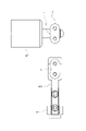
回動部421には、洗浄体411を保持した保持部412を取り付けるためのジョイントJが設けられており、このジョイントJには、保持部412の取り付け方法を手で触って確認するための目印となる1つ又は2つ以上の突起などの取付ガイドが形成されている。
具体的には、図8に示すように、例えば、取付ガイドとして、ジョイントJの1つの面に1つの突起Tが形成されているものを挙げることができる。この突起Tの位置と保持部412の取り付け向きとを予め定めておくことによって、もしセル11の内部が暗くて見えにくいような場合であっても、ユーザは突起Tの位置を確認することによって保持部412を所望の向きに取り付けることができる。また、保持部412側に、前述した突起Tを収容する凹部Cが形成されており、保持部412をジョイントJに取り付けた際に突起Tと凹部Cとがかみ合って、ジョイントJに保持部412を取り付けた際のクリック感を発生させるようにしても良い。
このように構成した濁度測定装置100を用いて、セル11の内面を洗浄機構4によって洗浄する手順及び方法としては、例えば、以下のようなものを挙げることができる。
測定空間11aに収容された測定対象液について測定が行われている測定時には、図3、5、7に示すように、洗浄機構4の駆動部42が洗浄部41の洗浄体411が測定空間11aとは反対側の位置で停止するようにしてある。
測定空間11aに収容された測定対象液について測定が行われている測定時には、図3、5、7に示すように、洗浄機構4の駆動部42が洗浄部41の洗浄体411が測定空間11aとは反対側の位置で停止するようにしてある。
そして測定が終了した後、できるだけ早いタイミングで洗浄体411が測定空間11aの内部に入り込むようにモータ部422から与えられるトルクによって回動部421が回動し、洗浄部41を前述した中心軸Xの周りで測定空間11aの開口11cの下部から測定空間11aに入り、測定空間11aの開口11cの上部から連通空間11bに抜けるように、例えば、一回転させる。
このとき、測定空間11aに入り込んだ洗浄部41の先端に配置された洗浄体411の先端が、入射窓12a、透過光出射窓13a及び散乱光出射窓14aにそれぞれ接触して、これらの表面の汚れをふき取るようにしてある。
このとき、測定空間11aに入り込んだ洗浄部41の先端に配置された洗浄体411の先端が、入射窓12a、透過光出射窓13a及び散乱光出射窓14aにそれぞれ接触して、これらの表面の汚れをふき取るようにしてある。
このように構成した濁度測定装置100によれば、セル11の内部に測定空間11aと、この測定空間11aを取り囲む連通空間11bとを設け、測定時には洗浄機構4の全体が連通空間11b内に配置されるようにしているので、セルの内部に測定空間11aだけを設けて、その内部に洗浄部や駆動部の一部を配置している従来の濁度測定装置に比べて、測定空間11aの大きさを小さくすることができる。その結果、入射窓12aと出射窓13a、14aとを洗浄する洗浄機構4を備えながらも、入射窓12aと出射窓13a、14aとの間に形成される光路長をできるだけ短くすることができる。
洗浄体411が、入射窓12a、透過光出射窓13a及び散乱光出射窓14aのすべてに接触する形状となっており、駆動部42が洗浄部41を一度回転させるだけでこれら3つの窓を一度に洗浄することができるので、できるだけ短時間で入射窓12a、透過光出射窓13a及び散乱光出射窓14aを洗浄することができる。そのため、セル11に連続的に流れ込んでくる測定対象液を連続して測定し続ける場合であっても、入射窓12a、透過光出射窓13a及び散乱光出射窓14aの洗浄のために測定を止めることなく、測定の合間にこれらの窓を洗浄しながら連続して測定を続けることが可能である。船舶の排水の濁度測定など、測定と測定との間隔を数十秒以内にする必要がある場合には、本実施形態の効果が特に顕著に発揮される。
セル11に測定対象液を導入する導入口11dと、セル11から測定対象液を導出する導出口11eが連通空間11bに形成されており、導入口11dが測定空間11aよりも下側に、導出口11eが測定空間11aよりも上側に形成されているので、測定対象液に異物が混入している場合であっても、測定空間11aに異物が滞留することをできるだけ避けることができる。また測定対象液に気泡が混入している場合であっても、測定空間11aに気泡が留まりにくいので、測定精度をより向上させることができる。
測定空間11aが上下方向に開口するものであり、散乱光出射面142も上下方向に対して平行に配置されているので、より異物や気泡が測定空間11a内に滞留しにくい構造となっている。
セル11に導入口11dに対して突出する突出部111が形成されているので、導入口11dからセル11の内部に流入した測定対象液が突出部111にぶつかって乱流となるので、セル11の内部における測定対象液の滞留をできるだけ抑えることができる。
洗浄部41を回転させる際の中心軸Xが、測定空間11aを形成している入射面11a1及び透過光出射面11a2に対して垂直、すなわち、入射面11a1と透過光出射面11a2との間に形成される透過光の光路及び散乱光出射面11a3に対して平行に設けられているので、洗浄部41の形状をできるだけ単純な形状にすることができる。
駆動部42が洗浄部41を測定空間11aの下側から上側に向けて回転させるものであるので、汚れを測定空間11aよりも上側に形成された導出口11eに向けて排出することができる。
測定時に洗浄体411が、連通空間11b内の測定空間11aが形成されている側とは反対側に位置するようにしてあるので、洗浄部41が測定空間11aの下側などにある場合に比べて、測定空間11aに流れ込む測定対象液の流れを妨げることが無く好ましい。
測定時に洗浄体411が、連通空間11b内の測定空間11aが形成されている側とは反対側に位置するようにしてあるので、洗浄部41が測定空間11aの下側などにある場合に比べて、測定空間11aに流れ込む測定対象液の流れを妨げることが無く好ましい。
入射窓12aを形成する入射窓形成部材122が、レンズと一体に形成されているものであるので、光源121と入射窓形成部材122との間に別体のレンズを配置する場合に比べてスペースを省くことができる。また、入射窓形成部材122を光源121の基板121aなどに固定するだけでよいので、別途レンズを光源121に対して位置決めする手間を省くことができる。本実施形態では、入射窓形成部材122を固定するプレート部材123を3点止めしており、さらに真鍮からなるレンズ抑え124を備えているので、入射窓形成部材122がずれてしまうことをできるだけ抑えることができる。
本発明は、前述した実施形態に限られるものではない。
例えば、洗浄体の形状は、前述したものに限られない。また洗浄体は、入射窓、透過光出射窓及び散乱光出射窓にほぼ同時に接触するものに限られず、少しずれて接触するものとしても良いし、向きを変えて洗浄部を複数回駆動させることによって、入射窓、透過光出射窓及び散乱光出射窓をそれぞれ洗浄するものとしても良い。
例えば、洗浄体の形状は、前述したものに限られない。また洗浄体は、入射窓、透過光出射窓及び散乱光出射窓にほぼ同時に接触するものに限られず、少しずれて接触するものとしても良いし、向きを変えて洗浄部を複数回駆動させることによって、入射窓、透過光出射窓及び散乱光出射窓をそれぞれ洗浄するものとしても良い。
洗浄機構が回動部を備えるものでなくても良く、例えば、スライド部を備えており、予め設けられたレール等に沿って洗浄部をスライドさせて測定空間に送り込むものとしても良い。
前述した実施形態では、透過光検出部と散乱光検出部を両方備えた場合を説明したが、透過光検出部のみを備えるものとしても良いし、散乱光検出部のみを備えるもの等としても良い。また散乱光検出部が90度散乱光以外の散乱光を検出するものとしても良い。
測定空間は、洗浄体が測定空間の内部に入り込む開口を有するものであればよく、上下方向に開口しているものに限らず、側面のみが開口する形状等であっても良い。
前述した中心軸は、回動部が洗浄部を回動させることによって、洗浄部が測定空間内部に入り込んで、入射窓、透過光射出窓及びまたは散乱光射出窓を洗浄できるように設けられていればよく、例えば、図9に示すように、洗浄部が中心軸に対して斜めになるように回動部に取り付けられている場合等には、中心軸が測定空間に形成された開口に対して斜めに設けられていてもよい。中心軸が図9に示した角度以外の角度で設けられている場合であっても同様に本発明の効果を奏することができることは言うまでもない。
さらに言えば、回動部が洗浄部を回動させることによって、洗浄部が測定空間内部に入り込んで、入射窓、透過光射出窓及びまたは散乱光射出窓を洗浄できるように設けられている限り、中心軸が測定空間の内部と交差するものとしても良い。
その他、本発明の趣旨に反しない範囲での変更が可能である。
さらに言えば、回動部が洗浄部を回動させることによって、洗浄部が測定空間内部に入り込んで、入射窓、透過光射出窓及びまたは散乱光射出窓を洗浄できるように設けられている限り、中心軸が測定空間の内部と交差するものとしても良い。
その他、本発明の趣旨に反しない範囲での変更が可能である。
本発明によれば、入射窓及び出射窓を洗浄する洗浄体を備える洗浄機構を設けながらも、光路長が従来よりも短い濁度測定装置を提供することができる。
Claims (9)
- 光源と光検出部との間に形成されて測定対象液を収容する測定空間を有し、前記光源からの光を前記測定空間に導く入射窓及び前記測定空間からの光を前記光検出部に導く出射窓を有するセルと、
前記入射窓及び前記出射窓を洗浄する洗浄機構とを備え、
前記洗浄機構は、前記入射窓及び前記出射窓を洗浄する洗浄体と、前記測定空間の外部に設けられ、測定時において前記洗浄体を前記測定空間の外部に退避させるとともに、洗浄時に前記洗浄体を前記測定空間内に移動させる駆動部とを有し、
前記洗浄体が、前記駆動部によって所定の中心軸周りに回転されるものであり、
前記中心軸が、前記測定空間の外部に設けられているものであることを特徴とする濁度測定装置。 - 前記測定空間に連通する連通空間をさらに有し、
前記洗浄体が前記連通空間に退避されるものである、請求項1記載の濁度測定装置。 - 前記測定空間は、互いに対向する第1面及び第2面と、当該第1面及び第2面を接続する第3面とから形成されており、
前記第1面に前記入射窓が形成されており、前記第2面に透過光を測定するための透過光出射窓が形成されており、
前記第3面に散乱光を測定するための散乱光出射窓が形成されているものである、請求項1又は2に記載の濁度測定装置。 - 前記洗浄体が、前記測定空間に入り込んだ状態で、前記入射窓、前記透過光出射窓及び前記散乱光出射窓に接触するものである、請求項3に記載の濁度測定装置。
- 前記セルが、内部に測定対象液を導入する導入口と、内部から前記測定対象液を導出する導出口とを有し、
前記導入口が、前記測定空間よりも下側に配置されており、
前記導出口が、前記測定空間よりも上側に位置するように配置されているものであることを特徴とする、請求項1~4のいずれか一項に記載の濁度測定装置。 - 前記測定空間が上下方向に開口するとともに、前記第3面が前記上下方向に対して平行に設けられている、請求項3に記載の濁度測定装置。
- 前記連通空間が、前記測定空間の前記第1面、前記第2面及び前記第3面以外の開口部を取り囲むように形成されているものであり、
前記セルが、内部に測定対象液を導入する導入口と、内部から前記測定対象液を導出する導出口とを有し、前記導入口及び前記導出口が前記連通空間に形成されている、請求項2を引用する請求項3に記載の濁度測定装置。 - 前記入射窓を形成している窓部材が、前記光源からの光を前記セルの内部に集光させるレンズと一体に形成されているものである、請求項1~7のいずれか一項に記載の濁度測定装置。
- 前記測定対象液が、船舶から排出される排水である請求項1~8のいずれか一項に記載の濁度測定装置。
Priority Applications (1)
| Application Number | Priority Date | Filing Date | Title |
|---|---|---|---|
| JP2023529518A JPWO2022264532A1 (ja) | 2021-06-17 | 2022-02-25 |
Applications Claiming Priority (2)
| Application Number | Priority Date | Filing Date | Title |
|---|---|---|---|
| JP2021-101222 | 2021-06-17 | ||
| JP2021101222 | 2021-06-17 |
Publications (1)
| Publication Number | Publication Date |
|---|---|
| WO2022264532A1 true WO2022264532A1 (ja) | 2022-12-22 |
Family
ID=84526129
Family Applications (1)
| Application Number | Title | Priority Date | Filing Date |
|---|---|---|---|
| PCT/JP2022/007893 WO2022264532A1 (ja) | 2021-06-17 | 2022-02-25 | 濁度測定装置 |
Country Status (2)
| Country | Link |
|---|---|
| JP (1) | JPWO2022264532A1 (ja) |
| WO (1) | WO2022264532A1 (ja) |
Citations (5)
| Publication number | Priority date | Publication date | Assignee | Title |
|---|---|---|---|---|
| JPS4726360B1 (ja) * | 1968-01-22 | 1972-07-15 | ||
| JPS55141054U (ja) * | 1979-03-30 | 1980-10-08 | ||
| JPS56154646A (en) * | 1980-04-30 | 1981-11-30 | Yamatake Honeywell Co Ltd | Method and device of automatic washing control of optical turbidity measuring apparatus |
| JP2010060364A (ja) * | 2008-09-02 | 2010-03-18 | Horiba Ltd | 試料測定装置 |
| JP2014081280A (ja) * | 2012-10-16 | 2014-05-08 | Horiba Advanced Techno Co Ltd | 色度計 |
-
2022
- 2022-02-25 WO PCT/JP2022/007893 patent/WO2022264532A1/ja active Application Filing
- 2022-02-25 JP JP2023529518A patent/JPWO2022264532A1/ja active Pending
Patent Citations (5)
| Publication number | Priority date | Publication date | Assignee | Title |
|---|---|---|---|---|
| JPS4726360B1 (ja) * | 1968-01-22 | 1972-07-15 | ||
| JPS55141054U (ja) * | 1979-03-30 | 1980-10-08 | ||
| JPS56154646A (en) * | 1980-04-30 | 1981-11-30 | Yamatake Honeywell Co Ltd | Method and device of automatic washing control of optical turbidity measuring apparatus |
| JP2010060364A (ja) * | 2008-09-02 | 2010-03-18 | Horiba Ltd | 試料測定装置 |
| JP2014081280A (ja) * | 2012-10-16 | 2014-05-08 | Horiba Advanced Techno Co Ltd | 色度計 |
Also Published As
| Publication number | Publication date |
|---|---|
| JPWO2022264532A1 (ja) | 2022-12-22 |
Similar Documents
| Publication | Publication Date | Title |
|---|---|---|
| US7469601B2 (en) | Flow meter using digital signals | |
| US7593107B2 (en) | Method and system for diffusion attenuated total reflection based concentration sensing | |
| KR20140068759A (ko) | 광학 분석 장치 | |
| WO2022264532A1 (ja) | 濁度測定装置 | |
| CN110887801A (zh) | 基于光谱法对复杂水体进行长时间原位探测的装置及方法 | |
| US8902427B2 (en) | System for measuring properties of test samples in fluid | |
| WO2010035612A1 (ja) | 液体濃度計 | |
| WO2023004423A1 (en) | Fluorescence and scatter and absorption spectroscopic apparatus with a sapphire tube and method for analyzing inline low level hydrocarbon in a flow medium | |
| US8927922B2 (en) | Fluid diagnostic devices and methods of using the same | |
| EP4137814A1 (en) | Optical measurement device and water quality analysis system | |
| US20040100630A1 (en) | Particle size distribution analyzer | |
| KR20190037035A (ko) | 큐벳의 자동세정이 가능한 흡광도 측정장치 | |
| CN213121592U (zh) | 一种光谱水质探头和光谱水质检测装置 | |
| JP4284077B2 (ja) | 水質計 | |
| US3628873A (en) | Method of continuously determining the degree of pollution of translucent liquids and apparatus therefor | |
| JP2008070245A (ja) | 流体試料用フローセル | |
| KR101420181B1 (ko) | 오염 모니터링 광센서 및 이를 이용한 수질오염 측정장치 | |
| JPH11118715A (ja) | 水質計および水質測定方法 | |
| KR100414446B1 (ko) | 부유물농도측정장치 | |
| JPS6033391Y2 (ja) | 油分濃度計のワイパ装置 | |
| JP4671485B2 (ja) | フローセル装置 | |
| JP2020165852A (ja) | 光学分析装置 | |
| JP2561971Y2 (ja) | 水質チェッカー | |
| JPS62228933A (ja) | 自動化学分析装置 | |
| WO2023149455A1 (ja) | 測定計、測定装置、測定システム、及び測定方法 |
Legal Events
| Date | Code | Title | Description |
|---|---|---|---|
| 121 | Ep: the epo has been informed by wipo that ep was designated in this application |
Ref document number: 22824532 Country of ref document: EP Kind code of ref document: A1 |
|
| WWE | Wipo information: entry into national phase |
Ref document number: 2023529518 Country of ref document: JP |
|
| NENP | Non-entry into the national phase |
Ref country code: DE |