WO2022264407A1 - 電動機、空気調和機、および制御基板 - Google Patents
電動機、空気調和機、および制御基板 Download PDFInfo
- Publication number
- WO2022264407A1 WO2022264407A1 PCT/JP2021/023218 JP2021023218W WO2022264407A1 WO 2022264407 A1 WO2022264407 A1 WO 2022264407A1 JP 2021023218 W JP2021023218 W JP 2021023218W WO 2022264407 A1 WO2022264407 A1 WO 2022264407A1
- Authority
- WO
- WIPO (PCT)
- Prior art keywords
- voltage
- electric motor
- low
- circuit
- power supply
- Prior art date
- Legal status (The legal status is an assumption and is not a legal conclusion. Google has not performed a legal analysis and makes no representation as to the accuracy of the status listed.)
- Ceased
Links
Images






Classifications
-
- H—ELECTRICITY
- H02—GENERATION; CONVERSION OR DISTRIBUTION OF ELECTRIC POWER
- H02P—CONTROL OR REGULATION OF ELECTRIC MOTORS, ELECTRIC GENERATORS OR DYNAMO-ELECTRIC CONVERTERS; CONTROLLING TRANSFORMERS, REACTORS OR CHOKE COILS
- H02P25/00—Arrangements or methods for the control of AC motors characterised by the kind of AC motor or by structural details
- H02P25/16—Arrangements or methods for the control of AC motors characterised by the kind of AC motor or by structural details characterised by the circuit arrangement or by the kind of wiring
-
- H—ELECTRICITY
- H02—GENERATION; CONVERSION OR DISTRIBUTION OF ELECTRIC POWER
- H02K—DYNAMO-ELECTRIC MACHINES
- H02K11/00—Structural association of dynamo-electric machines with electric components or with devices for shielding, monitoring or protection
- H02K11/30—Structural association with control circuits or drive circuits
- H02K11/33—Drive circuits, e.g. power electronics
-
- F—MECHANICAL ENGINEERING; LIGHTING; HEATING; WEAPONS; BLASTING
- F24—HEATING; RANGES; VENTILATING
- F24F—AIR-CONDITIONING; AIR-HUMIDIFICATION; VENTILATION; USE OF AIR CURRENTS FOR SCREENING
- F24F1/00—Room units for air-conditioning, e.g. separate or self-contained units or units receiving primary air from a central station
- F24F1/06—Separate outdoor units, e.g. outdoor unit to be linked to a separate room comprising a compressor and a heat exchanger
- F24F1/38—Fan details of outdoor units, e.g. bell-mouth shaped inlets or fan mountings
-
- F—MECHANICAL ENGINEERING; LIGHTING; HEATING; WEAPONS; BLASTING
- F24—HEATING; RANGES; VENTILATING
- F24F—AIR-CONDITIONING; AIR-HUMIDIFICATION; VENTILATION; USE OF AIR CURRENTS FOR SCREENING
- F24F11/00—Control or safety arrangements
- F24F11/88—Electrical aspects, e.g. circuits
-
- H—ELECTRICITY
- H02—GENERATION; CONVERSION OR DISTRIBUTION OF ELECTRIC POWER
- H02K—DYNAMO-ELECTRIC MACHINES
- H02K1/00—Details of the magnetic circuit
- H02K1/06—Details of the magnetic circuit characterised by the shape, form or construction
- H02K1/12—Stationary parts of the magnetic circuit
- H02K1/18—Means for mounting or fastening magnetic stationary parts on to, or to, the stator structures
-
- H—ELECTRICITY
- H02—GENERATION; CONVERSION OR DISTRIBUTION OF ELECTRIC POWER
- H02K—DYNAMO-ELECTRIC MACHINES
- H02K11/00—Structural association of dynamo-electric machines with electric components or with devices for shielding, monitoring or protection
- H02K11/0094—Structural association with other electrical or electronic devices
-
- H—ELECTRICITY
- H02—GENERATION; CONVERSION OR DISTRIBUTION OF ELECTRIC POWER
- H02K—DYNAMO-ELECTRIC MACHINES
- H02K2211/00—Specific aspects not provided for in the other groups of this subclass relating to measuring or protective devices or electric components
- H02K2211/03—Machines characterised by circuit boards, e.g. pcb
Definitions
- the present disclosure relates to electric motors, air conditioners, and control boards equipped with inverters.
- Control of conventional brushless DC (direct current) motors was control that could be achieved with a simple circuit configuration (combination circuit only) such as 120° energization control, so almost no noise was generated from the power supply circuit. .
- complex controls such as 150° energization control, sine wave energization control, phase control, and sensorless control are performed, so the circuit configuration of the control unit becomes complicated and the clock frequency increases. . Therefore, a lot of noise came to occur.
- an inductor is connected to the power supply line between the power receiving unit of the microcomputer and the reference voltage power supply circuit that outputs a high voltage, and the inductor removes noise.
- the present disclosure has been made in view of the above, and aims to obtain an electric motor capable of sufficiently reducing noise.
- the electric motor of the present disclosure includes a stator, a rotor, and a control board that supplies current to the stator.
- the control board has a high voltage circuit connected to the high voltage power supply and a low voltage circuit connected to the low voltage power supply.
- the high-voltage circuit includes an inverter that converts the input DC voltage to AC voltage and supplies it to the stator, and the low-voltage circuit includes a control unit that controls the inverter, connecting the low-voltage power supply and the low-voltage circuit.
- a first inductor is arranged in the low-voltage power supply line, which is the line that carries the voltage.
- the electric motor according to the present disclosure has the effect of sufficiently reducing noise.
- FIG. 1 is a diagram showing a configuration example of an electric motor according to Embodiment 1;
- FIG. FIG. 2 is a diagram showing a circuit configuration of a built-in board included in the electric motor according to the first embodiment;
- FIG. 4 is a diagram showing a first arrangement example of inductors on the built-in substrate according to the first embodiment;
- FIG. 4 is a diagram showing a second arrangement example of inductors on the built-in substrate according to the first embodiment;
- FIG. 4 is a diagram showing a third arrangement example of inductors on the built-in substrate according to the first embodiment;
- FIG. 4 is a diagram showing a fourth arrangement example of inductors on the built-in substrate according to the first embodiment;
- FIG. 2 is a diagram showing a first example of the top surface configuration of the built-in substrate according to the first embodiment; Diagram for explaining the relationship between temperature and inductance value
- FIG. 4 is a diagram showing a second example of the top surface configuration of the built-in substrate according to the first embodiment;
- FIG. 2 is a diagram schematically showing the inside of the electric motor according to Embodiment 1;
- FIG. 4 is a diagram showing inductance frequency characteristics of an inductor included in the electric motor according to Embodiment 1;
- FIG. 10 is a diagram showing a configuration example of an air conditioner according to Embodiment 2;
- FIG. 4 is a diagram for explaining a low-voltage power generation circuit included in an electric motor of an air conditioner according to Embodiment 2;
- FIG. 2 is a diagram showing a configuration example of a processing circuit when a control unit included in the electric motor according to Embodiments 1 and 2 is realized by a processor and a memory;
- FIG. 4 is a diagram showing an example of a processing circuit in the case where a control unit included in the electric motor according to Embodiments 1 and 2 is configured with dedicated hardware;
- FIG. 1 is a diagram showing a configuration example of an electric motor according to Embodiment 1.
- the electric motor 1 is a brushless DC motor.
- a part of the electric motor 1 is shown in cross-section for explanation of the configuration.
- FIG. 1 shows a radial gap type brushless DC motor, the electric motor 1 of Embodiment 1 is not limited to a radial gap type brushless DC motor.
- the electric motor 1 includes a rotor 30, a stator 20, a built-in board 11 as a control board, and a mold resin 12.
- a rotating shaft 31 is inserted into the rotor 30 .
- the stator 20 is provided on the outer circumference of the rotor 30 .
- the built-in substrate 11 has a substrate circuit which is a circuit for controlling the driving of the rotor 30 .
- the stator 20 , the built-in substrate 11 and the mold resin 12 are fixed by the mold stator 10 .
- the molded stator 10 is obtained by integrally molding the stator 20 and the built-in substrate 11 . That is, the stator 20 and the built-in substrate 11 are fixed by the molded stator 10 so as to be integrated. Inside the molded stator 10, there is provided a recess formed so as to accommodate the rotor 30 therein.
- the built-in substrate 11 is integrated with the stator 20 with a mold resin 12 having a dielectric constant higher than that of air (for example, a resin with a relative dielectric constant of 3 to 4).
- a mold resin 12 having a dielectric constant higher than that of air for example, a resin with a relative dielectric constant of 3 to 4.
- the stator 20 has a plurality of stator cores 21 , insulators 23 integrally molded with the stator cores 21 , and windings 22 .
- the stator core 21 is configured by laminating electromagnetic steel sheets.
- Insulator 23 insulates stator core 21 and winding 22 .
- the stator 20 is configured by winding the windings 22 around each slot of the stator core 21 integrally molded with the insulator 23.
- the winding 22 is made of copper, aluminum, or the like.
- An output-side bearing 33 that rotatably supports the rotating shaft 31 is provided at one end of the rotating shaft 31 .
- a non-output side bearing 34 that rotatably supports the rotating shaft 31 is provided at the other end of the rotating shaft 31 .
- the anti-output side bearing 34 is covered with a conductive bracket 60.
- the bracket 60 has a press-fitting portion 61 fitted to the inner peripheral portion of the molded stator 10 so as to close the opening of the recess provided in the molded stator 10 . Also, the outer ring of the anti-output side bearing 34 is fitted inside the bracket 60 .
- the built-in substrate 11 includes a power IC (Integrated Circuit) (power IC 80 to be described later) that supplies power to the windings 22, a control section 70 to be described later, and a magnetic sensor 50 that detects the position of the rotor 30. with a circuit containing
- the built-in substrate 11 is arranged perpendicular to the axial direction of the rotating shaft 31 between the output-side bearing 33 and the stator 20 and fixed to the insulator 23 . Also, the substrate circuit of the built-in substrate 11 and the winding 22 are connected via a winding terminal.
- the built-in substrate 11 is provided with a lead outlet portion 14 from which a lead wire 13 for connection with a host system is led out.
- a host system is a system in which the electric motor 1 is mounted.
- the lead wire 13 is connected to, for example, an air conditioner unit side substrate (such as an indoor unit substrate 211 to be described later).
- passive components such as operational amplifiers, comparators, regulators, diodes, resistors, capacitors, and fuses are arranged on the built-in substrate 11 .
- the shape of the built-in substrate 11 is disc-shaped with a through hole formed in the center.
- a rotary shaft 31 is passed through a through hole provided in the built-in substrate 11 .
- the built-in substrate 11 is arranged inside the electric motor 1 so that the upper surface and the bottom surface are perpendicular to the axial direction of the rotating shaft 31 .
- a rotor insulating portion 32 that is an annular member is arranged on the outer peripheral portion of the rotating shaft 31 .
- the rotor 30 has magnets 40 arranged inside the molded stator 10 .
- the magnet 40 is arranged at a position facing the stator core 21 on the outer peripheral side of the rotating shaft 31 and the rotor insulating portion 32 .
- the magnet 40 is composed of a cylindrical permanent magnet. Magnet 40 is fixed to rotating shaft 31 .
- the magnet 40 is manufactured by injection molding a bonded magnet composed of a ferrite magnet or a rare earth magnet (samarium iron nitrogen, neodymium, etc.) mixed with a thermoplastic resin material.
- a magnet is incorporated in the mold for injection molding of the magnet 40, and the magnet 40 is molded while being oriented.
- the magnet 40 has, in the axial direction of the rotating shaft 31, a sensor magnet portion which is a portion close to the magnetic sensor 50 and a main magnet portion which is a portion other than the sensor magnet portion.
- the sensor magnet section causes the magnetic sensor 50 to detect the position of the rotor 30 .
- the main magnet section causes the rotor 30 to generate rotational force according to the magnetic flux generated by the windings 22 .
- the outer diameter of the built-in substrate 11 on the side of the magnetic sensor 50 is smaller than the other outer diameter portions. That is, in the magnet 40, the outer diameter of the sensor magnet portion is smaller than the outer diameter of the main magnet portion. Due to the shape of the magnet 40 , magnetic flux easily flows into the magnetic sensor 50 mounted on the built-in substrate 11 .
- the magnetic sensor 50 is located far from the windings 22 of the stator 20, that is, close to the rotating shaft 31, in order to minimize the influence of the magnetic flux generated from the windings 22 of the stator 20.
- FIG. 1 shows the case where the main magnet section and the sensor magnet section are composed of one magnet 40, the main magnet section and the sensor magnet section may be composed of separate magnets. .
- the magnetic sensor 50 may be configured using a Hall IC whose output signal is a digital signal, or may be configured using a Hall element whose output signal is an analog signal. That is, the magnetic sensor 50 may be of a type that detects the position of the rotor 30 using a Hall IC, or may be of a type that detects the position of the rotor 30 using a Hall element.
- the Hall IC may be a Hall IC (first type Hall IC) that detects the position of the rotor 30 by the first method, or a Hall IC that detects the position of the rotor 30 by the second method. It may be an IC (a Hall IC of the second method).
- the sensor section and the amplifier section are composed of separate semiconductor chips.
- the sensor section is made of a semiconductor other than silicon, and the amplifier section is made of silicon.
- the Hall IC of the first method is hereinafter referred to as a non-silicon Hall IC.
- the sensor section and the amplifier section are composed of one silicon semiconductor chip.
- the sensor section is arranged so that the center position of the sensor section is different from the center of the IC body.
- a non-silicon semiconductor such as indium antimonide (InSb) is used in the sensor portion of the non-silicon Hall IC.
- This non-silicon semiconductor has advantages such as better sensitivity and less offset due to stress strain than silicon semiconductor.
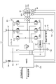
- FIG. 2 is a diagram showing a circuit configuration of a built-in board included in the electric motor according to the first embodiment; In FIG. 2, the built-in substrate 11, the winding 22, and the magnetic sensor 50 are shown.
- an inductor 73A is arranged on the low-voltage power supply line for noise countermeasures.
- the details of the noise countermeasure inductor 73A will be described later.
- the built-in substrate 11 includes an inverter IC that drives and controls the electric motor 1 having windings 22 and an overcurrent detection resistor 75 .
- the built-in substrate 11 includes a power IC 80 , a control section 70 and an overcurrent detection resistor 75 .
- the power IC 80 has an inverter 81 , a gate drive circuit 82 and a protection circuit 83 .
- the control unit 70 is connected to the host system, the gate drive circuit 82, the ground 79A, and the magnetic sensor 50.
- the controller 70 is also connected to a low-voltage power supply 78 via a connection point 48 .
- An inductor 73A is arranged between the connection point 48 and the low-voltage power supply 78 . That is, the control unit 70 is connected to the low-voltage power supply 78 via the connection point 48 and the inductor 73A.
- the control unit 70 is connected to the ground 79C via the connection point 41, the connection point 42, and the overcurrent detection resistor 75. As shown in FIG.
- the gate drive circuit 82 is connected to the low voltage power supply 78 via the connection point 48 and the inductor 73A, and is connected to the high voltage power supply 77 via the connection point 47 .
- a low-voltage power supply 78 outputs a voltage lower than that of the high-voltage power supply 77 .
- the high voltage power supply 77 is a bus power supply.
- the gate drive circuit 82 is connected to the inverter 81 . Also, the gate drive circuit 82 is connected to the protection circuit 83 and the ground 79B via the connection point 43 .
- the protection circuit 83 is connected to the connection points 41 and 43 . That is, the protection circuit 83 is connected to the ground 79C via the connection point 41, the connection point 42, and the overcurrent detection resistor 75. FIG. Also, the protection circuit 83 is connected to the ground 79B via the connection point 43 .
- the inverter 81 is connected to the electric motor 1 having the windings 22 . Also, the inverter 81 is connected to the ground 79C via the connection point 42 and the overcurrent detection resistor 75 . Grounds 79A to 79C are common grounds of the same potential. Grounds 79A to 79C are referred to as grounds 79 in the following description.
- the power IC 80 is also called an IPM (Intelligent Power Module).
- the inverter 81 comprises six power transistors 81A-81F.
- the six power transistors 81A to 81F may be configured separately, or may be configured as one IC.
- the gate drive circuit 82 may be configured with one IC, or may be configured with three separate three-phase ICs.
- the gate drive circuit 82 and the control unit 70 may be configured by one IC.
- the control unit 70 may be composed of one dedicated IC (control IC), or may be composed of a microcomputer (hereinafter referred to as a microcomputer) or the like.
- the power transistors 81A to 81F are composed of superjunction MOSFETs (Metal Oxide Semiconductor Field Effect Transistors), planar MOSFETs, or IGBTs (Insulated Gate Bipolar Transistors). .
- superjunction MOSFETs Metal Oxide Semiconductor Field Effect Transistors
- planar MOSFETs planar MOSFETs
- IGBTs Insulated Gate Bipolar Transistors
- the magnetic sensor 50 detects the magnetic pole position of the rotor 30 corresponding to the magnetic flux position
- the built-in substrate 11 controls the electric motor 1 based on the magnetic pole position.
- the built-in substrate 11 may perform sensorless control of the electric motor 1 while estimating the magnetic pole position from the current flowing through the windings 22 and the voltage applied and generated to the windings 22 .
- the built-in substrate 11 may amplify a current signal obtained by using a shunt resistor and a current sensor with an operational amplifier or the like. Further, the built-in substrate 11 may use a comparator to generate a signal to the control section 70 for overcurrent protection from this current signal.
- the voltage (eg, 15 V) that drives the gates of the power transistors 81A to 81F may differ from the microcomputer power supply voltage (eg, 5 V) that drives the control unit 70 such as a microcomputer.
- the electric motor 1 uses a regulator to generate another power supply from one power supply supplied from the outside.
- the built-in board 11 is supplied with a 15V power supply from the outside, and the regulator generates a 5V power supply and supplies it to the built-in board 11 .
- This regulator may be incorporated in gate drive circuit 82 or power IC 80 .
- the inverter 81 converts the input DC voltage into a three-phase AC voltage consisting of U-phase, V-phase, and W-phase, and supplies the three-phase AC voltage to the windings 22 of the stator 20 .
- Power transistor 81A is a U-phase upper arm power transistor
- power transistor 81B is a V-phase upper arm power transistor
- power transistor 81C is a W-phase upper arm power transistor.
- Power transistor 81D is a U-phase lower arm power transistor
- power transistor 81E is a V-phase lower arm power transistor
- power transistor 81F is a W-phase lower arm power transistor.
- the electric motor 1 has, as windings 22, a U-phase winding 22U, a V-phase winding 22V, and a W-phase winding 22W.
- U-phase winding 22U is connected to power transistors 81A and 81D.
- the V-phase winding 22V is connected to power transistors 81B and 81E.
- W-phase winding 22W is connected to power transistors 81C and 81F.
- the gate drive circuit 82 controls turning on and off of the power transistors 81A to 81F according to switching signals received from the control section 70.
- Three magnetic sensors 50 are arranged around the winding 22 .
- the three magnetic sensors 50 each output a magnetic pole position signal corresponding to the position of the rotor 30 to the controller 70 .
- the protection circuit 83 protects the inverter 81 and the gate drive circuit 82. For example, the protection circuit 83 prevents a high current from flowing back to the gate drive circuit 82 from the ground 79 side. Moreover, when at least one of the inverter 81 and the gate drive circuit 82 becomes hot, the protection circuit 83 turns off all the power transistors 81A to 81F of the inverter 81 to prevent element breakdown due to high temperature.
- the overcurrent detection resistor 75 is connected to the lower arm switches of the power transistors 81D-81F.
- the built-in substrate 11 has an overcurrent detector (not shown) that detects overcurrent.
- the overcurrent detection unit monitors the voltage of the overcurrent detection resistor 75, and turns off the power transistors 81A to 81F when the voltage of the overcurrent detection resistor 75 exceeds a specific value, thereby preventing overcurrent in the winding 22. Prevent current flow and realize overcurrent protection.
- the overcurrent detection signal input from the overcurrent detection resistor 75 to the control unit 70 corresponds to the voltage across the overcurrent detection resistor 75 becoming equal to or higher than a specific value.
- the overcurrent detector implements overcurrent protection based on the overcurrent detection signal.
- the overcurrent detection section may be built in the control section 70 or may be built in the gate drive circuit 82 .
- a temperature sensing element may be provided on the built-in substrate 11 or the like.
- the control unit 70 forcibly turns off the power transistors 81A to 81F upon receiving a signal indicating an abnormal temperature from the temperature sensitive element.
- the control unit 70 generates a switching signal for controlling on/off of the power transistors 81A to 81F at a specific frequency (hereinafter referred to as carrier frequency) according to the speed command signal received from the host system.
- the control unit 70 outputs a switching signal to the gate drive circuit 82 to perform pulse width modulation (PWM) control on the power transistors 81A to 81F.
- PWM pulse width modulation
- the control unit 70 estimates the magnetic pole position of the rotor 30 based on the magnetic pole position signal input from the magnetic sensor 50, and calculates the rotation speed of the rotor 30 from the estimated magnetic pole position.
- the control unit 70 outputs a rotational speed signal indicating the calculated rotational speed to the host system.
- control unit 70 may be a dedicated IC such as an ASIC (Application Specific Integrated Circuit). Also, the control unit 70 may be configured to have a memory that stores programs and a CPU (Central Processing Unit) that executes processes according to the programs. A hardware configuration of the control unit 70 will be described later.
- ASIC Application Specific Integrated Circuit
- CPU Central Processing Unit
- the electric motor 1 which is a brushless DC motor, obtains rotational power by switching six power transistors 81A to 81F at appropriate timings in the case of three-phase, according to the magnetic pole positions of the magnets 40 of the rotor 30. A switching signal used for this switching is generated by the controller 70 . The principle of operation of this electric motor 1 will be described.
- control unit 70 estimates the magnetic pole position of the rotor 30 based on the magnetic pole position signal from the magnetic sensor 50 or the current value of the current flowing through the windings 22 .
- Control unit 70 generates a switching signal for switching power transistors 81A-81F in accordance with the magnetic pole position of rotor 30 and a speed command signal output from a host system.
- the gate drive circuit 82 switches the power transistors 81A to 81F on and off according to the switching signal generated by the control section 70.
- the switching timings of turning on and off of the six power transistors 81A to 81F are the same as the rising and falling edges of the detection signals from the three Hall ICs. Therefore, in the 120° energization control, the control section 70 can be configured with a combinational circuit that does not require a clock.
- control unit 70 is composed of a complicated digital circuit including a clock.
- the timing between each rise and fall of the detection signal by the three Hall ICs is estimated finely.
- the sensorless control is control that does not use the magnetic sensor 50 .
- control is performed by estimating the magnetic pole position from the current value detected by a current detection resistor, current detection transformer, or the like. That is, in the case of sensorless control, the controller 70 estimates the magnetic pole position based on the current flowing through the winding 22 and the voltage applied to the winding 22, which requires complicated processing and calculations. For this reason, in the case of sensorless control, the control unit 70 requires a more complicated circuit and a higher clock frequency.
- the clock frequency of the control unit 70 should be 100 times or more the carrier frequency, which is the switching frequency of the power transistors 81A to 81F.
- the inductor 73A for noise countermeasures arranged on the built-in substrate 11 will be described.
- the inductor 73A is arranged in the low-voltage power supply line of the built-in substrate 11 as a countermeasure against noise.
- the noise in the first embodiment refers to noise (EMI: Electro Magnetic Interference) generated from the electric motor 1 and products mounted with the electric motor 1 .
- This noise includes noise terminal voltage noise, noise power noise, and radiation noise.
- a low-voltage power supply line is a line that connects the low-voltage power supply 78 and a circuit (low-voltage circuit) in the built-in substrate 11 that operates at a low voltage.
- an inductor may be arranged in the high-voltage power supply line of the built-in substrate 11 .
- the high-voltage power supply line is a line that connects the high-voltage power supply 77 and a circuit (high-voltage circuit) in the built-in substrate 11 that operates at a high voltage.
- an inductor may be placed on the ground (GND) line of the built-in substrate 11 .
- a ground line is a line that connects the ground 79 and a circuit in the built-in substrate 11 .
- a ground line for the low-voltage circuit and a ground line for the high-voltage circuit may be separately arranged.
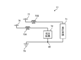
- FIG. 3 is a diagram showing a first arrangement example of inductors on the built-in substrate according to the first embodiment.
- the low-voltage circuit 72 is connected to the low-voltage power supply 78 and the high-voltage circuit 71 is connected to the high-voltage power supply 77 .
- the low-voltage circuit 72 and the high-voltage circuit 71 are connected to the connection point 45 , and the connection point 45 is connected to the ground 79 .
- the low voltage circuit 72 is composed of, for example, a digital circuit including a sequential circuit.
- the low-voltage circuit 72 includes a first circuit that is part of the gate drive circuit 82, a control section 70, and a protection circuit 83.
- High voltage circuit 71 includes a second circuit that is part of gate drive circuit 82 and inverter 81 .
- the gate drive circuits 82 the first circuit included in the low voltage circuit 72 and the second circuit included in the high voltage circuit 71 are different circuits.
- one inductor 73A is arranged.
- the inductor 73A which is the first inductor, is arranged on the low-voltage power supply line connecting the low-voltage circuit 72 and the low-voltage power supply 78 .
- the built-in substrate 11 can reduce noise generated in the built-in substrate 11 by the inductor 73A.
- FIG. 4 is a diagram showing a second arrangement example of inductors on the built-in substrate according to the first embodiment.
- the second arrangement example of the built-in substrate 11 two inductors 73A and 73B are arranged.
- the inductor 73B which is the second inductor, is arranged on the high voltage power supply line connecting the high voltage circuit 71 and the high voltage power supply 77 .
- the built-in substrate 11 can reduce noise generated in the built-in substrate 11 by the inductors 73A and 73B.
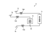
- FIG. 5 is a diagram showing a third arrangement example of inductors on the built-in substrate according to the first embodiment.
- the third arrangement example of the built-in substrate 11 three inductors 73A to 73C are arranged.
- the inductor 73C is arranged on the ground line connecting the connection point 45 and the ground 79 .
- the built-in substrate 11 can reduce noise generated in the built-in substrate 11 by the inductors 73A to 73C.
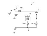
- FIG. 6 is a diagram showing a fourth arrangement example of inductors on the built-in substrate according to the first embodiment.
- the fourth arrangement example of the built-in substrate 11 four inductors 73A, 73B, 73D and 73E are arranged.
- the inductor 73D is arranged on the ground line that connects the low voltage circuit 72 and the connection point 45 .
- the inductor 73E is arranged on the ground line connecting the high voltage circuit 71 and the connection point 45 .
- the built-in substrate 11 can reduce noise generated in the built-in substrate 11 by the inductors 73A, 73B, 73D, and 73E.
- FIG. 7 is a diagram showing the circuit configuration of the built-in substrate of the comparative example.
- the built-in substrate of the comparative example includes a low voltage circuit 72X and a high voltage circuit 71X.
- the low voltage circuit 72X is a circuit similar to the low voltage circuit 72
- the high voltage circuit 71X is a circuit similar to the high voltage circuit 71.
- FIG. 7 is a diagram showing the circuit configuration of the built-in substrate of the comparative example.
- the built-in substrate of the comparative example includes a low voltage circuit 72X and a high voltage circuit 71X.
- the low voltage circuit 72X is a circuit similar to the low voltage circuit 72
- the high voltage circuit 71X is a circuit similar to the high voltage circuit 71.
- the low-voltage circuit 72X is connected to a low-voltage power supply 78X, which is similar to the low-voltage power supply 78.
- the high-voltage circuit 71X is connected to a high-voltage power supply 77X, which is similar to the high-voltage power supply 77.
- FIG. Also, the low-voltage circuit 72X and the high-voltage circuit 71X are connected to a connection point 45X, which is a connection point similar to the connection point 45, and the connection point 45X is connected to the ground 79X.
- no inductor is arranged on the low-voltage power supply line that connects the low-voltage circuit 72X and the low-voltage power supply 78X. Also, no inductor is arranged on the high-voltage power supply line connecting the high-voltage circuit 71X and the high-voltage power supply 77X. Further, no inductor is arranged on the ground line from the low voltage circuit 72X to the ground 79X, and no inductor is arranged on the ground line from the high voltage circuit 71X to the ground 79X. Therefore, the built-in board of the comparative example cannot reduce the noise generated in the built-in board of the comparative example.
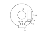
- FIG. 8 is a diagram showing a first example of the top surface configuration of the built-in substrate according to the first embodiment.
- the upper structure of the built-in substrate 11 shown in FIG. 5 will be described.
- the shape of the built-in substrate 11 is disc-shaped with a through hole 35 formed in the center.
- the rotary shaft 31 is passed through the through hole 35 .
- a power IC 80 that supplies power to the windings 22, inductors 73A to 73C, and a control section 70 are arranged on the upper surface of the built-in substrate 11.
- FIG. Although not shown, an overcurrent detection resistor 75 and the like are arranged on the upper surface or the bottom surface of the built-in substrate 11 .
- the inductors 73A-73C are arranged closer to the lead outlet 14 than the power IC 80 including the power transistors 81A-81F. In other words, the inductors 73A to 73C are arranged at positions where the distance to the lead output portion 14 is shorter than the distance to the power IC 80 .
- the inductors 73A to 73C are less susceptible to the heat generated by the power transistors 81A to 81F, and changes in the inductance values of the inductors 73A to 73C due to temperature are reduced.
- the noise reduction effect decreases due to impedance unmatching and the like.
- the noise reduction effect increases because the change in the inductance value is small. That is, the inductors 73A-73C are less susceptible to the heat generated from the power transistors 81A-81F. Therefore, the built-in substrate 11 can suppress a change in noise removal performance caused by a change in the inductance value due to the temperature characteristics of the inductors 73A to 73C.
- the inductors 73A to 73C are arranged at positions closer to the lead outlet portion 14 than the power IC 80, board wiring to the built-in board 11 is facilitated. As a result, the size of the built-in substrate 11 can be reduced, and the size reduction of the built-in substrate 11 can reduce the manufacturing cost of the electric motor 1 . In addition, the miniaturization of the built-in substrate 11 shortens the wiring length in the built-in substrate 11, so that noise can be reduced.
- the impedance decreases as the temperature rises, which may greatly deteriorate the noise reduction effect.
- the case where the inductance value has a negative correlation characteristic with respect to temperature is not limited to the case where the inductance value has a negative correlation characteristic with respect to the entire temperature range. negative correlation).
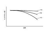
- FIG. 9 is a diagram for explaining the relationship between temperature and inductance value.
- the horizontal axis of the graph shown in FIG. 9 is the temperature, and the vertical axis is the inductance value.
- FIG. 9 shows inductance temperature characteristics for each magnitude of current.
- the inductance temperature characteristic 74A is the inductance temperature characteristic when the current of the first current value flows through the inductor.
- the inductance temperature characteristic 74B is the inductance temperature characteristic when the current of the second current value flows through the inductor.
- the inductance temperature characteristic 74C is the inductance temperature characteristic when the current of the third current value flows through the inductor. First current value ⁇ second current value ⁇ third current value.
- the impedance decreases as the temperature rises.
- the greater the current value of the current flowing through the inductor the greater the temperature dependence of the inductor.
- the saturation magnetic flux density of the magnetic material inside the inductor decreases, causing the inductance value to decrease significantly due to temperature rise, and the noise reduction effect tends to worsen.
- the inductors 73A to 73C are arranged closer to the lead outlet portion 14 than the power IC 80, so temperature rise can be suppressed. Therefore, the built-in substrate 11 can suppress a decrease in impedance and maintain the noise reduction effect.
- the power IC 80 and the control section 70 may be configured by one IC.
- the inductors 73D and 73E are arranged on the built-in substrate 11, the inductors 73D and 73E are arranged at positions closer to the lead outlet section 14 than the power IC 80, for example.
- FIG. 10 is a diagram showing a second example of the top surface configuration of the built-in substrate according to the first embodiment.
- FIG. 10 shows a region of the upper surface of the built-in substrate 11 with a central angle of about 90 degrees, and the other regions are omitted.
- a module 85 for supplying power to the windings 22 is arranged on the upper surface of the built-in substrate 11 .
- the module 85 includes circuitry that performs the functions of the power IC 80 and the control section 70 .
- the built-in substrate 11 shown in FIG. 10 has fewer electronic components to be mounted than the built-in substrate 11 shown in FIG. 8, the mounting area of the electronic components becomes smaller. As a result, the board area of the built-in board 11 can be reduced.
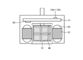
- FIG. 11 is a diagram schematically showing the inside of the electric motor according to Embodiment 1.
- FIG. 11 shows a cross-sectional configuration of the electric motor 1 .
- the inductors 73A to 73C are arranged on the surface of the built-in substrate 11 opposite to the windings 22 . That is, the inductors 73A to 73C are arranged on the side of the built-in substrate 11 opposite to the stator. In other words, when stator core 21 and windings 22 are arranged at positions facing the first main surface of built-in substrate 11, inductors 73A to 73C are positioned opposite to the first main surface of built-in substrate 11. It is arranged on the second main surface, which is the side surface. For example, when the bottom surface of built-in substrate 11 faces stator core 21 and windings 22 , inductors 73 A to 73 C are arranged on the top surface of built-in substrate 11 .
- the inductors 73A to 73C are less susceptible to heat generated from the windings 22.
- the built-in substrate 11 can suppress a change in noise removal performance caused by a change in the inductance value due to the temperature characteristics of the inductors 73A to 73C.
- the inductors 73A to 73C are arranged on the opposite side of the built-in substrate 11 to the power IC 80, for example.
- inductors 73 A to 73 C are arranged on the second main surface of built-in substrate 11 .
- the inductors 73A to 73C are arranged on the top surface of the built-in substrate 11.
- the built-in substrate 11 can suppress a change in noise removal performance caused by a change in the inductance value due to the temperature characteristics of the inductors 73A to 73C.
- FIG. 12 is a diagram showing inductance frequency characteristics of an inductor included in the electric motor according to Embodiment 1.
- FIG. The horizontal axis of the graph shown in FIG. 12 is frequency, and the vertical axis is impedance.
- FIG. 12 shows an inductance frequency characteristic 73AF of the inductor 73A of the low voltage power supply 78 and an inductance frequency characteristic 73BF of the inductor 73B of the high voltage power supply 77.
- the inductor 73A of the low-voltage power supply 78 and the inductor 73B of the high-voltage power supply 77 have maximum impedance values at specific frequencies.
- the inductor 73A of the low-voltage power supply 78 has a maximum impedance value at a frequency higher than that of the inductor 73B of the high-voltage power supply 77 .
- the carrier frequency in the control unit 70 is several kHz to several tens of kHz, and the clock frequency in the control unit 70 is several MHz to several tens of MHz. That is, control using the low-voltage power supply 78 has a higher frequency than control using the high-voltage power supply 77 . For this reason, the inductor 73A of the low-voltage power supply 78 uses an inductor having the maximum impedance at a higher frequency than the inductor 73B of the high-voltage power supply 77, thereby further enhancing the noise reduction effect.
- An inductor may be used in which the frequency at which the impedance of the inductor 73A reaches its maximum value is lower than the frequency at which the impedance of the inductor 73B reaches its maximum value.
- an inductor may be used in which the frequency at which the impedance of the inductor 73A reaches its maximum value is the same as the frequency at which the impedance of the inductor 73B reaches its maximum value.
- the electric motor 1 can sufficiently reduce noise. becomes. For example, even if a large amount of noise occurs due to the circuit of the control unit 70 being complicated and the frequency of the clock being increased, the electric motor 1 can sufficiently reduce the noise. .
- the built-in board 11 controls the inverter 81 while estimating the magnetic pole position of the rotor 30, the built-in board 11 requires a digital circuit. In this case, the clock frequency becomes 100 times or more the carrier frequency, resulting in increased noise. Even in this case, the electric motor 1 can sufficiently reduce noise by the inductor 73A.
- control unit 70 is composed of a microcomputer that operates with a high-frequency clock and has many functional blocks, noise increases. Even in this case, the electric motor 1 can sufficiently reduce noise by the inductor 73A.
- the stator 20 and the built-in substrate 11 are integrally molded with the mold resin 12, noise increases. Even in this case, the electric motor 1 can sufficiently reduce noise by the inductor 73A.
- Embodiment 2 Next, Embodiment 2 will be described with reference to FIGS. 13 and 14.
- FIG. 1 electric motor 1 described in Embodiment 1 is applied to an air conditioner.
- FIG. 13 is a diagram showing a configuration example of an air conditioner according to Embodiment 2.
- the air conditioner 200 includes an indoor unit 210 and an outdoor unit 220 connected to the indoor unit 210 via refrigerant pipes 230 .
- the indoor unit 210 is equipped with an indoor blower 212
- the outdoor unit 220 is equipped with an outdoor blower 223.
- Indoor unit fan 212 and outdoor unit fan 223 incorporate electric motor 1 described in Embodiment 1 as a drive source.
- the electric motor 1 incorporated in the indoor blower 212 is the first electric motor
- the electric motor 1 incorporated in the outdoor blower 223 is the second electric motor.
- the indoor unit fan 212 and the outdoor unit fan 223 are, for example, line flow fans (registered trademark) (also called cross-flow fans or cross-flow fans).
- the indoor unit 210 also includes an indoor unit board (unit board) 211 that controls the indoor unit 210 and the like.
- the indoor unit board 211 cannot be placed on both sides of the indoor unit 210, and the indoor unit board 211 is arranged in front of the indoor unit 210.
- the indoor unit board 211 is arranged in front of the indoor unit 210 .
- the lead wire 13 connecting between the electric motor 1 and the indoor unit board 211 becomes longer, so that noise becomes worse. In particular, radiation noise radiated from the lead wire 13 increases. Even in this case, since electric motor 1 including inductor 73A and the like is incorporated in indoor unit 210 in Embodiment 2, noise can be reduced by inductor 73A.
- FIG. 14 is a diagram for explaining a low-voltage power generation circuit included in the electric motor of the air conditioner according to Embodiment 2.
- the built-in substrate 11 includes an inductor 73A, a low-voltage circuit 72, a low-voltage power supply 78, and the like.
- the built-in board 11 is connected to the indoor unit board 211 .
- a low-voltage power generation circuit that outputs voltage to the low-voltage power supply 78 is arranged on the indoor unit board 211 .
- the low-voltage power generation circuit is composed of a switching regulator 213, for example.
- the switching regulator 213 is connected to the low voltage power supply 78 .
- the switching regulator 213 is connected to the low voltage circuit 72 and the ground 79 via the connection point 44 .
- the switching regulator 213 converts the input DC voltage into a specific DC voltage and outputs it to the low-voltage power supply 78 .
- the switching regulator 213 When the low-voltage power generation circuit of the indoor unit board 211 is composed of the switching regulator 213, the switching regulator 213 generates a lot of noise. Even in this case, the electric motor 1 can sufficiently reduce noise by the inductor 73A. In this case, the electric motor 1 can improve EMI characteristics, which are jamming waves, and improve EMS (Electro Magnetic Susceptibility) characteristics, which are electrode sensitivity. That is, the electric motor 1 can improve EMC (Electro Magnetic Compatibility) characteristics, which are electromagnetic compatibility.
- EMI characteristics which are jamming waves
- EMS Electro Magnetic Susceptibility
- EMC Electro Magnetic Compatibility
- the electric motor 1 can be used by being mounted on, for example, a ventilation fan, a home appliance, a machine tool, and the like.
- the electric motor 1 is incorporated in the air conditioner 200, so that the electric motor 1 can sufficiently reduce noise.
- the control unit 70 is implemented by a processing circuit.
- the processing circuitry may be a processor and memory executing programs stored in the memory, or may be dedicated hardware.
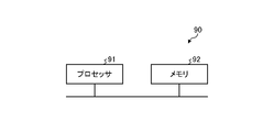
- FIG. 15 is a diagram showing a configuration example of a processing circuit in the case of implementing the control unit provided in the electric motor according to Embodiments 1 and 2 with a processor and memory.
- a processing circuit 90 shown in FIG. 15 is the control unit 70 and includes a processor 91 and a memory 92 .
- each function of the processing circuit 90 is implemented by software, firmware, or a combination of software and firmware.
- Software or firmware is written as a program and stored in memory 92 .
- each function is realized by the processor 91 reading and executing the program stored in the memory 92.
- the processing circuit 90 includes a memory 92 for storing a program that results in the processing of the control unit 70 being executed.
- This program can also be said to be a program for causing the control unit 70 to execute each function realized by the processing circuit 90 .
- This program may be provided by a storage medium storing the program, or may be provided by other means such as a communication medium.
- processor 91 is a CPU (central processing unit, processing unit, arithmetic unit, microprocessor, microcomputer, DSP (Digital Signal Processor)) or system LSI (Large Scale Integration).
- memory 92 RAM (Random Access Memory) and ROM (Read Only Memory).
- FIG. 16 is a diagram showing an example of a processing circuit in the case where the control unit provided in the electric motor according to Embodiments 1 and 2 is configured with dedicated hardware.
- the processing circuit 93 shown in FIG. 16 corresponds to, for example, a single circuit, a composite circuit, a programmed processor, a parallel programmed processor, an ASIC, an FPGA (Field Programmable Gate Array), or a combination thereof.
- the processing circuit 93 may be partially realized by dedicated hardware and partially realized by software or firmware.
- the processing circuitry 93 can implement each of the functions described above by dedicated hardware, software, firmware, or a combination thereof.
- the gate drive circuit 82, the protection circuit 83, the circuits provided in the indoor unit board 211, and the like can also be realized by hardware similar to the control unit 70.
Landscapes
- Engineering & Computer Science (AREA)
- Power Engineering (AREA)
- Chemical & Material Sciences (AREA)
- Combustion & Propulsion (AREA)
- Mechanical Engineering (AREA)
- General Engineering & Computer Science (AREA)
- Microelectronics & Electronic Packaging (AREA)
- Inverter Devices (AREA)
- Control Of Ac Motors In General (AREA)
Abstract
Description
図1は、実施の形態1にかかる電動機の構成例を示す図である。電動機1は、ブラシレスDCモータである。図1では、電動機1の構成の説明のために、一部を断面構造で示している。なお、図1は、ラジアルギャップ形のブラシレスDCモータを示しているが、実施の形態1の電動機1はラジアルギャップ形のブラシレスDCモータに限らない。
つぎに、図13および図14を用いて実施の形態2について説明する。実施の形態2では、実施の形態1で説明した電動機1を空気調和機に適用する。
Claims (17)
- 固定子と、
回転子と、
前記固定子に電流を供給する制御基板と、
を備え、
前記制御基板は、
高圧電源に接続された高圧回路と、
低圧電源に接続された低圧回路と、
を有し、
前記高圧回路には、入力される直流電圧を交流電圧に変換して前記固定子に供給するインバータが含まれ、
前記低圧回路には、前記インバータを制御する制御部が含まれ、
前記低圧電源と前記低圧回路とを接続するラインである低圧電源ラインには、第1のインダクタが配置されている電動機。 - 前記低圧回路は、順序回路を含むデジタル回路で構成され、
前記デジタル回路のクロック周波数はキャリア周波数の100倍以上の周波数である請求項1に記載の電動機。 - 前記制御基板は、前記回転子の磁極位置を推定しながら前記インバータを制御する請求項1または2に記載の電動機。
- 前記制御基板は、150°通電制御、正弦波通電制御、位相制御、またはセンサレス制御によって前記インバータを制御する請求項3に記載の電動機。
- 前記制御部は、マイクロコンピュータで構成されている請求項1から4の何れか1つに記載の電動機。
- 前記制御基板は、
前記高圧電源と前記高圧回路とを接続するラインである高圧電源ラインに配置された第2のインダクタを具備する請求項1から5の何れか1つに記載の電動機。 - 前記第1のインダクタにおいてインピーダンスが最大値となる周波数が、前記第2のインダクタにおいてインピーダンスが最大値となる周波数よりも高い請求項6に記載の電動機。
- 前記第1のインダクタにおいてインピーダンスが最大値となる周波数が、前記第2のインダクタにおいてインピーダンスが最大値となる周波数よりも低い請求項6に記載の電動機。
- 前記制御基板および前記固定子は、樹脂を用いて一体成型されている請求項1から8の何れか1つに記載の電動機。
- 前記第1のインダクタは、前記インバータを含んだ集積回路までの距離よりもリード線が引き出されたリード口出し部までの距離の方が短くなる位置に配置されている請求項1から9の何れか1つに記載の電動機。
- 前記固定子は、前記制御基板の第1の主面に対向する位置に配置されるとともに、前記第1のインダクタは、前記制御基板の第1の主面とは反対側の面である第2の主面上に配置されている請求項1から10の何れか1つに記載の電動機。
- 前記集積回路は、前記制御基板の第1の主面上に配置されるとともに、前記第1のインダクタは、前記制御基板の第1の主面とは反対側の面である第2の主面上に配置されている請求項10に記載の電動機。
- 前記低圧回路には、前記インバータを駆動するドライブ回路に含まれる第1の回路が含まれ、
前記高圧回路には、前記ドライブ回路に含まれる第2の回路が含まれている請求項1から12の何れか1つに記載の電動機。 - 請求項1から13の何れか1つに記載の電動機を備える空気調和機。
- 室内機と、
室外機と、
前記室内機に配置されるとともに前記電動機のうちの第1の電動機によって駆動されて送風する室内機用送風機と、
前記室外機に配置されるとともに前記電動機のうちの第2の電動機によって駆動されて送風する室外機用送風機と、
をさらに備え、
前記室内機用送風機および前記室外機用送風機は、ラインフローファン(登録商標)であり、
前記室内機の前面に、前記室内機の制御を行う室内機基板が配置されている請求項14に記載の空気調和機。 - 前記低圧電源に電圧を出力する低圧電源生成回路をさらに備え、
前記低圧電源生成回路は、スイッチングレギュレータで構成されている請求項14または15に記載の空気調和機。 - 電動機が備える固定子に電流を供給する制御基板であって、
高圧電源に接続された高圧回路と、
低圧電源に接続された低圧回路と、
を有し、
前記高圧回路には、入力される直流電圧を交流電圧に変換して前記固定子に供給するインバータが含まれ、
前記低圧回路には、前記インバータを制御する制御部が含まれ、
前記低圧電源と前記低圧回路とを接続するラインである低圧電源ラインには、第1のインダクタが配置されている制御基板。
Priority Applications (5)
| Application Number | Priority Date | Filing Date | Title |
|---|---|---|---|
| PCT/JP2021/023218 WO2022264407A1 (ja) | 2021-06-18 | 2021-06-18 | 電動機、空気調和機、および制御基板 |
| JP2023528918A JP7433527B2 (ja) | 2021-06-18 | 2021-06-18 | 電動機、空気調和機、および制御基板 |
| US18/554,489 US12438420B2 (en) | 2021-06-18 | 2021-06-18 | Electric motor, air conditioner, and control board |
| DE112021007852.6T DE112021007852T5 (de) | 2021-06-18 | 2021-06-18 | Elektromotor, Klimaanlage und Steuerplatine |
| CN202180099128.6A CN117441290A (zh) | 2021-06-18 | 2021-06-18 | 电动机、空调机以及控制基板 |
Applications Claiming Priority (1)
| Application Number | Priority Date | Filing Date | Title |
|---|---|---|---|
| PCT/JP2021/023218 WO2022264407A1 (ja) | 2021-06-18 | 2021-06-18 | 電動機、空気調和機、および制御基板 |
Publications (1)
| Publication Number | Publication Date |
|---|---|
| WO2022264407A1 true WO2022264407A1 (ja) | 2022-12-22 |
Family
ID=84526387
Family Applications (1)
| Application Number | Title | Priority Date | Filing Date |
|---|---|---|---|
| PCT/JP2021/023218 Ceased WO2022264407A1 (ja) | 2021-06-18 | 2021-06-18 | 電動機、空気調和機、および制御基板 |
Country Status (5)
| Country | Link |
|---|---|
| US (1) | US12438420B2 (ja) |
| JP (1) | JP7433527B2 (ja) |
| CN (1) | CN117441290A (ja) |
| DE (1) | DE112021007852T5 (ja) |
| WO (1) | WO2022264407A1 (ja) |
Citations (3)
| Publication number | Priority date | Publication date | Assignee | Title |
|---|---|---|---|---|
| JP2005057989A (ja) * | 2003-07-18 | 2005-03-03 | Matsushita Electric Ind Co Ltd | モータ駆動装置 |
| JP2010088297A (ja) * | 2003-04-30 | 2010-04-15 | Panasonic Corp | モータ駆動装置 |
| WO2018078719A1 (ja) * | 2016-10-25 | 2018-05-03 | 三菱電機株式会社 | 電力制御装置、電動機、空気調和機、および電動機の製造方法 |
Family Cites Families (2)
| Publication number | Priority date | Publication date | Assignee | Title |
|---|---|---|---|---|
| JP2005219625A (ja) | 2004-02-05 | 2005-08-18 | Koyo Seiko Co Ltd | パワーステアリング装置 |
| JP6184388B2 (ja) * | 2014-10-07 | 2017-08-23 | 三菱電機株式会社 | 電動機、空気調和機、および電動機の製造方法 |
-
2021
- 2021-06-18 CN CN202180099128.6A patent/CN117441290A/zh active Pending
- 2021-06-18 JP JP2023528918A patent/JP7433527B2/ja active Active
- 2021-06-18 WO PCT/JP2021/023218 patent/WO2022264407A1/ja not_active Ceased
- 2021-06-18 US US18/554,489 patent/US12438420B2/en active Active
- 2021-06-18 DE DE112021007852.6T patent/DE112021007852T5/de active Pending
Patent Citations (3)
| Publication number | Priority date | Publication date | Assignee | Title |
|---|---|---|---|---|
| JP2010088297A (ja) * | 2003-04-30 | 2010-04-15 | Panasonic Corp | モータ駆動装置 |
| JP2005057989A (ja) * | 2003-07-18 | 2005-03-03 | Matsushita Electric Ind Co Ltd | モータ駆動装置 |
| WO2018078719A1 (ja) * | 2016-10-25 | 2018-05-03 | 三菱電機株式会社 | 電力制御装置、電動機、空気調和機、および電動機の製造方法 |
Also Published As
| Publication number | Publication date |
|---|---|
| DE112021007852T5 (de) | 2024-04-25 |
| JP7433527B2 (ja) | 2024-02-19 |
| US20240204626A1 (en) | 2024-06-20 |
| CN117441290A (zh) | 2024-01-23 |
| US12438420B2 (en) | 2025-10-07 |
| JPWO2022264407A1 (ja) | 2022-12-22 |
Similar Documents
| Publication | Publication Date | Title |
|---|---|---|
| EP3014747B1 (en) | A control module for an electric motor or generator | |
| JP5206732B2 (ja) | インバータ装置、及び、それを用いた駆動装置 | |
| US11451119B2 (en) | Motor with a board having microcomputer and drive circuit, and air conditioning apparatus having the motor | |
| US20120307476A1 (en) | Control unit and driving apparatus using the same | |
| CN110168683B (zh) | 用于电动马达或发电机的电容器部件 | |
| US10848082B2 (en) | Driving device and driving method for motor, cooling device and electronic machine | |
| JP6727450B2 (ja) | 電動機、及び電動機を備えた空気調和機 | |
| JP5163536B2 (ja) | 誘起電圧検出回路とそれを有するモータ駆動用半導体装置及びモータ並びに空調機 | |
| KR101333798B1 (ko) | 차량용 모터 구동장치 및 이를 이용한 차량용 워터펌프 | |
| JP4557955B2 (ja) | モータ駆動回路及びモータ駆動方法並びに半導体集積回路装置 | |
| JP7433527B2 (ja) | 電動機、空気調和機、および制御基板 | |
| US10598393B2 (en) | Electric-power control device, electric motor, air-conditioning apparatus, and method for manufacturing electric motor | |
| US12088227B2 (en) | Electric motor and air-conditioning apparatus including the same | |
| JP7724980B2 (ja) | 電動機、空気調和機、および制御基板 | |
| TR2023016483T2 (tr) | Elektrik motoru, klima ve kontrol kartı. | |
| JP7003294B2 (ja) | 電動機およびそれを搭載した空気調和機 | |
| JP7807528B2 (ja) | 電動機および空気調和機 | |
| JP7337273B2 (ja) | 電力制御装置、電力制御装置を備えた電動機、および、電動機を備えた空気調和機 | |
| WO2023135743A1 (ja) | 電動機、空気調和機、および制御基板 | |
| WO2024201738A1 (ja) | 電動機および空気調和機 | |
| WO2021220427A1 (ja) | 電動機及び空気調和機 | |
| WO2025062520A1 (ja) | 電動機および空気調和機 |
Legal Events
| Date | Code | Title | Description |
|---|---|---|---|
| 121 | Ep: the epo has been informed by wipo that ep was designated in this application |
Ref document number: 21946082 Country of ref document: EP Kind code of ref document: A1 |
|
| ENP | Entry into the national phase |
Ref document number: 2023528918 Country of ref document: JP Kind code of ref document: A |
|
| WWE | Wipo information: entry into national phase |
Ref document number: 18554489 Country of ref document: US |
|
| WWE | Wipo information: entry into national phase |
Ref document number: 2023/016483 Country of ref document: TR |
|
| WWE | Wipo information: entry into national phase |
Ref document number: 202180099128.6 Country of ref document: CN |
|
| WWE | Wipo information: entry into national phase |
Ref document number: 202327084432 Country of ref document: IN |
|
| WWE | Wipo information: entry into national phase |
Ref document number: 2301008123 Country of ref document: TH |
|
| WWE | Wipo information: entry into national phase |
Ref document number: 112021007852 Country of ref document: DE |
|
| 122 | Ep: pct application non-entry in european phase |
Ref document number: 21946082 Country of ref document: EP Kind code of ref document: A1 |
|
| WWG | Wipo information: grant in national office |
Ref document number: 18554489 Country of ref document: US |