WO2022264398A1 - 流路切替装置およびそれが設けられた冷凍サイクル装置 - Google Patents
流路切替装置およびそれが設けられた冷凍サイクル装置 Download PDFInfo
- Publication number
- WO2022264398A1 WO2022264398A1 PCT/JP2021/023175 JP2021023175W WO2022264398A1 WO 2022264398 A1 WO2022264398 A1 WO 2022264398A1 JP 2021023175 W JP2021023175 W JP 2021023175W WO 2022264398 A1 WO2022264398 A1 WO 2022264398A1
- Authority
- WO
- WIPO (PCT)
- Prior art keywords
- flow path
- anisotropic
- flow
- channel
- refrigerant
- Prior art date
- Legal status (The legal status is an assumption and is not a legal conclusion. Google has not performed a legal analysis and makes no representation as to the accuracy of the status listed.)
- Ceased
Links
Images









Classifications
-
- F—MECHANICAL ENGINEERING; LIGHTING; HEATING; WEAPONS; BLASTING
- F25—REFRIGERATION OR COOLING; COMBINED HEATING AND REFRIGERATION SYSTEMS; HEAT PUMP SYSTEMS; MANUFACTURE OR STORAGE OF ICE; LIQUEFACTION SOLIDIFICATION OF GASES
- F25B—REFRIGERATION MACHINES, PLANTS OR SYSTEMS; COMBINED HEATING AND REFRIGERATION SYSTEMS; HEAT PUMP SYSTEMS
- F25B41/00—Fluid-circulation arrangements
- F25B41/20—Disposition of valves, e.g. of on-off valves or flow control valves
-
- F—MECHANICAL ENGINEERING; LIGHTING; HEATING; WEAPONS; BLASTING
- F25—REFRIGERATION OR COOLING; COMBINED HEATING AND REFRIGERATION SYSTEMS; HEAT PUMP SYSTEMS; MANUFACTURE OR STORAGE OF ICE; LIQUEFACTION SOLIDIFICATION OF GASES
- F25B—REFRIGERATION MACHINES, PLANTS OR SYSTEMS; COMBINED HEATING AND REFRIGERATION SYSTEMS; HEAT PUMP SYSTEMS
- F25B1/00—Compression machines, plants or systems with non-reversible cycle
-
- F—MECHANICAL ENGINEERING; LIGHTING; HEATING; WEAPONS; BLASTING
- F25—REFRIGERATION OR COOLING; COMBINED HEATING AND REFRIGERATION SYSTEMS; HEAT PUMP SYSTEMS; MANUFACTURE OR STORAGE OF ICE; LIQUEFACTION SOLIDIFICATION OF GASES
- F25B—REFRIGERATION MACHINES, PLANTS OR SYSTEMS; COMBINED HEATING AND REFRIGERATION SYSTEMS; HEAT PUMP SYSTEMS
- F25B13/00—Compression machines, plants or systems, with reversible cycle
-
- F—MECHANICAL ENGINEERING; LIGHTING; HEATING; WEAPONS; BLASTING
- F25—REFRIGERATION OR COOLING; COMBINED HEATING AND REFRIGERATION SYSTEMS; HEAT PUMP SYSTEMS; MANUFACTURE OR STORAGE OF ICE; LIQUEFACTION SOLIDIFICATION OF GASES
- F25B—REFRIGERATION MACHINES, PLANTS OR SYSTEMS; COMBINED HEATING AND REFRIGERATION SYSTEMS; HEAT PUMP SYSTEMS
- F25B41/00—Fluid-circulation arrangements
- F25B41/20—Disposition of valves, e.g. of on-off valves or flow control valves
- F25B41/26—Disposition of valves, e.g. of on-off valves or flow control valves of fluid flow reversing valves
-
- F—MECHANICAL ENGINEERING; LIGHTING; HEATING; WEAPONS; BLASTING
- F28—HEAT EXCHANGE IN GENERAL
- F28F—DETAILS OF HEAT-EXCHANGE AND HEAT-TRANSFER APPARATUS, OF GENERAL APPLICATION
- F28F3/00—Plate-like or laminated elements; Assemblies of plate-like or laminated elements
-
- F—MECHANICAL ENGINEERING; LIGHTING; HEATING; WEAPONS; BLASTING
- F25—REFRIGERATION OR COOLING; COMBINED HEATING AND REFRIGERATION SYSTEMS; HEAT PUMP SYSTEMS; MANUFACTURE OR STORAGE OF ICE; LIQUEFACTION SOLIDIFICATION OF GASES
- F25B—REFRIGERATION MACHINES, PLANTS OR SYSTEMS; COMBINED HEATING AND REFRIGERATION SYSTEMS; HEAT PUMP SYSTEMS
- F25B2500/00—Problems to be solved
- F25B2500/12—Sound
Definitions
- the present disclosure relates to a channel switching device and a refrigeration cycle device provided with the same.
- a bridge circuit consisting of four check valves is configured, and even if the direction of refrigerant flow changes according to the operation mode of cooling operation and heating operation, the direction of refrigerant flow in a certain section of the refrigerant circuit is kept in the same direction.
- a check valve unit has been proposed (see, for example, Patent Document 1).
- the check valve unit disclosed in Patent Document 1 is provided with four valve bodies, and each valve body mechanically moves up and down to control the flow of refrigerant.
- the valve body has a movable portion that mechanically operates, so there is a risk of abnormal noise being generated as the valve body slides.
- the present disclosure has been made to solve the above-described problems, and provides a flow path switching device that suppresses the generation of abnormal noise while ensuring the check valve function, and a refrigeration cycle device provided with the same. It is something to do.
- a flow path switching device is a flow path switching device provided in a refrigeration cycle device and configured by a plurality of plates, and includes a first flow port, a second flow port, and the first flow port. and the second flow port, and the flow path is a flow resistance of the refrigerant in the forward direction, which is the refrigerant flow direction from the first flow port to the second flow port.
- the anisotropic flow path has an anisotropic flow path in which a certain forward resistance is different from a reverse resistance, which is a flow resistance of the refrigerant in a direction opposite to the refrigerant flow direction from the second flow port to the first flow port. , a part of the anisotropic flow path is formed in a plate different from the plate in which one or both of the first circulation port and the second circulation port are formed, among the plurality of plates It is.
- a refrigeration cycle device includes a refrigerant circuit including a heat exchanger, and the flow path switching device provided in the refrigerant circuit.
- the function of the check valve can be ensured, so that the refrigerant automatically flows out.
- the flow direction can be switched. Since the flow path switching device is not provided with a movable part such as a valve body, it is possible to suppress the generation of abnormal noise due to the sliding motion.
- FIG. 1 is an exploded perspective view showing a configuration example of a flow path switching device according to Embodiment 1;
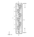
- FIG. 2 is a plan view of the first plate shown in FIG. 1;
- FIG. 3 is an enlarged view of the anisotropic channel shown in FIG. 2;
- FIG. FIG. 2 is a schematic diagram of a case where a coolant flows in the forward direction in the channel switching device shown in FIG. 1;
- FIG. 2 is a schematic diagram of a flow path switching device shown in FIG. 1 in which a refrigerant flows in the opposite direction;
- FIG. 2 is a refrigerant circuit diagram showing one configuration example of a refrigeration cycle device provided with the flow path switching device shown in FIG. 1 ;
- FIG. 11 is an exploded perspective view showing a configuration example of a flow path switching device according to Embodiment 2;
- Figure 8 is a plan view of the first plate shown in Figure 7;
- FIG. 8 is a diagram showing an example in which the flow path switching device shown in FIG. 7 is provided in a refrigeration cycle device;
- FIG. 11 is an exploded perspective view showing a configuration example of a flow path switching device according to Embodiment 3;
- 11 is a plan view of the first plate shown in FIG. 10;
- FIG. FIG. 11 is a diagram showing the flow of coolant when the coolant flows in from the fourth flow port and flows out from the third flow port in the channel switching device shown in FIG. 10 ;
- FIG. 11 is a diagram showing the flow of refrigerant when the refrigerant flows in from the third flow port and flows out from the fourth flow port in the channel switching device shown in FIG. 10 ;
- FIG. 11 is a plan view showing one configuration example of a first plate of Modification 1 in the flow path switching device according to Embodiment 3;
- FIG. 11 is a perspective view for explaining the configuration of a flow path switching device according to Embodiment 4;
- FIG. 11 is an exploded perspective view showing one configuration example of a flow path switching device according to Embodiment 4;
- FIG. 17 is a plan view of the first channel plate and the second channel plate shown in FIG. 16;
- FIG. 11 is a perspective view for explaining the configuration of a flow path switching device of Modification 2 in Embodiment 3;
- FIG. 11 is an exploded perspective view showing a configuration example of a flow path switching device of modification 2;
- FIG. 20 is a plan view of the first channel plate and the second channel plate shown in FIG. 19;
- FIG. 11 is a refrigerant circuit diagram showing a configuration example of a refrigeration cycle apparatus according to Embodiment 5;
- FIG. 22 is a diagram showing the direction of flow of refrigerant flowing through the flow path switching device during the cooling operation of the refrigeration cycle apparatus shown in FIG. 21;
- FIG. 22 is a diagram showing the direction of flow of refrigerant when the refrigeration cycle device shown in FIG. 21 performs heating operation;
- FIG. 22 is a diagram showing the direction of flow of the refrigerant flowing through the flow path switching device during the heating operation of the refrigeration cycle device shown in FIG. 21;
- FIG. 3 is an external perspective view showing a configuration example of a heat source side heat exchanger for explaining counterflow.
- 26 is a diagram showing an example of the temperature distribution of air when the heat source side heat exchanger
- a flow path switching device will be described with reference to the drawings.
- arrows of three axes (X-axis, Y-axis and Z-axis) defining directions are displayed in part of the drawing.
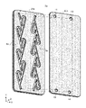
- FIG. 1 is an exploded perspective view showing a configuration example of a flow path switching device according to Embodiment 1.
- FIG. The channel switching device 1 has a configuration in which a first plate 2a and a second plate 2b are laminated. A groove-like channel 3 is formed in the first plate 2a.
- the flow paths 3 are arranged in parallel with respective surfaces of the first plate 2a and the second plate 2b that are laminated.
- the second plate 2b is provided with a first flow port 11 and a second flow port 12 serving as flow ports for refrigerant.
- the flow path 3 is formed by stacking the second plate 2b on the first plate 2a. Of the two ends 3 a and 3 b of the flow path 3 , the end 3 a is positioned at the first flow port 11 and the end 3 b is positioned at the second flow port 12 .
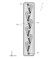
- FIG. 2 is a plan view of the first plate shown in FIG.
- the channel 3 has a plurality of anisotropic channels 5 .
- FIG. 1 shows a configuration example in which six anisotropic channels 5 are formed in the first plate 2a.
- One anisotropic channel 5 may be formed in the first plate 2a.
- portions positioned at the first flow port 11 and the second flow port 12 shown in FIG. 1 are indicated by dashed lines.
- a connection channel in which a plurality of anisotropic channels 5 are connected in series is called an anisotropic channel array.
- the flow direction from the first flow port 11 to the second flow port 12 is the forward direction
- the flow direction from the second flow port 12 to the first flow port 11 is the forward direction. in the opposite direction.
- the anisotropic flow path 5 has a forward resistance, which is the flow resistance of the coolant in the forward direction, and a reverse resistance, which is the flow resistance of the coolant in the reverse direction.
- the anisotropic flow path 5 has the characteristic that the reverse resistance is higher than the forward resistance.
- FIG. 3 is an enlarged view of the anisotropic flow path shown in FIG.
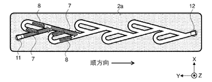
- the anisotropic flow path 5 includes a main flow path 7 in which a part of the refrigerant flowing in from the first circulation port 11 is branched, and a remaining flow path 7 except for a part of the refrigerant flowing in from the first circulation port 11. It has a secondary channel 8 into which the coolant flows and the remaining coolant joins the coolant flowing through the main channel 7 .
- arrows indicate the case where the coolant flows in the forward direction.
- the main flow path 7 has a main first straight portion 7a and a main second straight portion 7b.
- the main second straight portion 7b is located on the same straight line as the main first straight portion 7a.
- the main first straight portion 7a and the main second straight portion 7b are integrally formed.
- the sub-channel 8 is a U-shaped channel.
- the sub-flow path 8 has a straight first sub-straight portion 8a, a second sub-straight-line portion 8b longer than the first sub-straight portion 8a, and a U-curved curved portion 8c.
- the sub-first straight portion 8a and the sub-second straight portion 8b are arranged in parallel.
- the main flow path 7 and the sub-flow path 8 are connected at a first confluence point 9a and a second confluence point 9b.
- first confluence point 9a a first confluence point
- second confluence point 9b a second confluence point
- the secondary first straight portion 8a one end is connected to the main first straight portion 7a at a first junction 9a, and the other end is connected to the curved portion 8c.
- the secondary second linear portion 8b one end is connected to the main second linear portion 7b at a second junction 9b, and the other end is connected to the curved portion 8c.
- the angle ⁇ a is an acute angle.
- the angle ⁇ b is an acute angle formed by a straight line parallel to the main second straight portion 7b and a straight line parallel to the sub second straight portion 8b with respect to the second junction 9b.
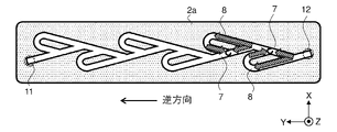
- the anisotropic flow path 5 shown in FIG. 3 when the refrigerant flows in the opposite direction from the second flow port 12 to the first flow port 11, the refrigerant 8 and shunted.
- the refrigerant flowing through the main flow path 7 joins the refrigerant flowing through the sub-flow path 8 . It merges with the coolant flowing through the main flow path 7 at an acute angle ⁇ a. Therefore, the coolant flowing through the main flow path 7 is blocked by the coolant flowing through the sub-flow path 8 at the first confluence point 9a.
- the anisotropic flow path 5 has anisotropy in the flow resistance of the internal flow path, and constitutes a Tesla valve structure in which the refrigerant flows significantly less in the reverse direction than in the forward direction.
- the flow path 3 shown in FIG. 2 has a structure in which the anisotropic flow paths 5 shown in FIG. 3 are connected in six stages. Focusing on two anisotropic channels 5 adjacent to each other in the direction of the Y-axis arrow shown in FIG. For example, in FIG. 3, if the anisotropic flow channel 5 closest to the first flow port 11 is the first-stage anisotropic flow channel 5, the second-stage anisotropic flow channel 5 is shown in FIG.
- the anisotropic channel 5 is connected to the first-stage anisotropic channel 5 in a mirror-inverted state. Specifically, the first-stage The upper end of the main channel 7 of the second-stage anisotropic channel 5 is connected to the second confluence 9b.
- One or both of the angles ⁇ a and ⁇ b may be appropriately set according to the design specifications of the reverse resistance.
- FIG. 1 also shows a configuration in which a first flow port 11 and a second flow port 12 are formed in a second plate 2b laminated on the upper surface (surface on the side of the Z-axis arrow) of the first plate 2a.
- either one of these two flow holes may be provided in a separate plate.
- another plate (not shown) is laminated on the lower surface of the first plate 2a (the surface opposite to the Z-axis arrow), and the second flow path is placed at a position corresponding to the position of the end 3b of the other plate A mouth 12 may be formed.
- a through hole is formed at the position of the end portion 3b in the first plate 2a.
- the second flow port 12 may not be provided in the second plate 2b.
- FIG. 4 is a schematic diagram of the flow path switching device shown in FIG. 1 when the refrigerant flows in the forward direction.
- FIG. 5 is a schematic diagram of the flow path switching device shown in FIG. 1 when the refrigerant flows in the opposite direction.
- the refrigerant flowing from the sub-flow path 8 into the main flow path 7 does not present a large flow resistance to the refrigerant flowing through the main flow path 7 .
- the flow switching device 1 has the characteristics of a Tesla valve in which the refrigerant flows easily in the forward direction but does not easily flow in the reverse direction.
- the channel switching device 1 shown in FIG. 1 By performing laser processing on the first plate 2a, the channel 3 is formed in the first plate 2a in a groove shape. By pressing the second plate 2b, the first circulation port 11 and the second circulation port 12 are formed in the second plate 2b. After the second plate 2b is overlaid on the first plate 2a, these two plates are adhered together.
- the second plate 2b serves as a cover plate that prevents leakage of the refrigerant flowing between the first flow port 11 and the second flow port 12. As shown in FIG.
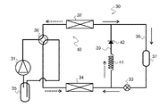
- FIG. 6 is a refrigerant circuit diagram showing one configuration example of a refrigeration cycle device provided with the flow path switching device shown in FIG. 1
- the refrigeration cycle device 30 has a compressor 31, a condenser 32, an expansion valve 33, and a cooler 34 functioning as an evaporator.
- Compressor 31, condenser 32, expansion valve 33, and cooler 34 are connected by refrigerant pipes to form a refrigerant circuit 40 through which refrigerant circulates.
- An accumulator 35 is provided on the refrigerant suction port side of the compressor 31 .
- a four-way valve 36 is provided on the refrigerant discharge port side of the compressor 31 . The four-way valve 36 is connected to the refrigerant discharge port of the compressor 31 , the accumulator 35 , the condenser 32 and the cooler 34 .
- a condenser 32 , an expansion valve 33 and a cooler 34 are connected by a refrigerant pipe 38 .
- a dryer 37 is provided between the condenser 32 and the expansion valve 33 in the refrigerant pipe 38 .
- a bypass circuit 39 is provided in parallel with the expansion valve 33 and the dryer 37 .
- a capillary tube 41 and a check valve 42 are connected to the bypass circuit 39 .
- the check valve 42 corresponds to the channel switching device 1 shown in FIG.
- Refrigerant discharged from the compressor 31 flows into the condenser 32 via the four-way valve 36 .
- the refrigerant that has exchanged heat with the air in the condenser 32 flows through the refrigerant pipe 38, but does not flow into the bypass circuit 39 because the check valve 42 is in the opposite direction.
- the refrigerant flowing through the refrigerant pipe 38 flows through the dryer 37 , is expanded in the expansion valve 33 , and then flows into the cooler 34 .
- the cooler 34 the refrigerant exchanges heat with the air in the air-conditioned space, thereby cooling the air in the air-conditioned space.
- the refrigerant After flowing through the cooler 34 , the refrigerant returns to the compressor 31 via the four-way valve 36 and the accumulator 35 .
- the expansion valve 33 is closed during the defrosting operation of the refrigeration cycle device 30 .
- High-temperature refrigerant discharged from the compressor 31 flows into the cooler 34 via the four-way valve 36 .
- the refrigerant melts the frost adhering to the cooler 34, and then flows into the bypass circuit 39 because the expansion valve 33 is closed.
- the refrigerant After flowing through the capillary tube 41, the refrigerant reaches the check valve 42. Since the check valve 42 is forward, the refrigerant flows through the check valve 42. The refrigerant that has flowed through the check valve 42 flows into the condenser 32 .
- the refrigerant After flowing through the condenser 32 , the refrigerant returns to the compressor 31 via the four-way valve 36 and the accumulator 35 . In this manner, the flow of refrigerant is controlled by the check valve 42 in accordance with the operation modes of the cooling operation and the defrosting operation performed by the refrigeration cycle device 30 .
- the channel switching device 1 of Embodiment 1 is composed of a plurality of plates, and includes a first flow port, a second flow port, and a flow path connecting the first flow port 11 and the second flow port 12 .
- the flow path 3 has a forward resistance, which is a flow resistance of the refrigerant in the forward flow direction of the refrigerant from the first flow port 11 to the second flow port 12, and a flow resistance from the second flow port 12 to the first flow.
- It has an anisotropic flow path 5 that differs from the reverse direction resistance, which is the flow resistance of the coolant in the direction opposite to the coolant flow direction to the port 11 .
- the anisotropic flow path 5 is formed in a plate different from the plate in which one or both of the first circulation port 11 and the second circulation port 12 are formed, among the plurality of plates.
- the first embodiment it has an anisotropic flow path that functions as a check valve. Therefore, the flow direction of the refrigerant can be automatically switched without a movable part such as a valve body. Since the flow path switching device 1 is not provided with a movable part, it is possible to suppress the generation of abnormal noise due to the sliding motion and reduce the noise caused by the movement of the movable part. In addition, since no moving part is provided, the valve body is not worn out due to chattering. Furthermore, since no movable portion is provided, foreign matter does not get caught in the movable portion, so it is possible to prevent the check valve from functioning properly when foreign matter gets caught.
- a plurality of anisotropic flow paths 5 are formed in one plate material.
- Embodiment 2 a plurality of anisotropic flow path arrays described in the first embodiment are provided.
- Embodiment 2 is a case where two anisotropic flow path arrays are provided.
- the same components as those described in the first embodiment are denoted by the same reference numerals, and detailed description thereof will be omitted.
- FIG. 7 is an exploded perspective view showing a configuration example of a flow path switching device according to Embodiment 2.
- FIG. The channel switching device 1a has a configuration in which a first plate 20a and a second plate 20b are laminated.
- a first anisotropic flow path array 6a and a second anisotropic flow path array 6b are formed in grooves on the first plate 20a.
- the second plate 20b is provided with a first flow port 11, a second flow port 12, a third flow port 13, and a fourth flow port 14, which are coolant flow ports.
- the first anisotropic flow path array 6a and the second anisotropic flow path array 6b are formed by overlapping the second plate 20b on the first plate 20a.
- FIG. 8 is a plan view of the first plate shown in FIG. In FIG. 8, portions located at the first through fourth flow ports 11 to 14 shown in FIG. 1 are indicated by dashed lines.
- the direction of coolant flow from the first flow port 11 to the second flow port 12 is the forward direction.
- the direction of refrigerant flow to is opposite.
- the direction of coolant flow from the fourth flow port 14 to the third flow port 13 is the forward direction.
- the direction of refrigerant flow to is opposite.
- the forward direction of the first anisotropic flow path array 6a and the forward direction of the second anisotropic flow path array 6b face each other. are arranged in parallel.
- FIG. 9 is a diagram showing an example in which the flow path switching device shown in FIG. 7 is provided in a refrigeration cycle device.
- a description will be given of a case where the refrigeration cycle device provided with the flow path switching device 1a is capable of switching between cooling operation and heating operation by, for example, switching the flow direction of the refrigerant with a four-way valve.
- the heat source side heat exchanger 45 is connected to the flow path switching device 1a.
- the heat source side heat exchanger 45 is connected to the refrigerant pipe 46 and the flow path switching device 1a is connected to the refrigerant pipe 47 .
- a compressor, a load-side heat exchanger, and an expansion valve (not shown) are connected to the refrigerant pipes 46 and 47 .
- the heat source side heat exchanger 45 has a heating heat exchanger 45a and a cooling heat exchanger 45b.
- the heating heat exchanger 45a is connected to the first anisotropic flow path array 6a.
- the cooling heat exchanger 45b is connected to the second anisotropic flow path array 6b.
- the heating heat exchanger 45a is designed to improve the heat exchange efficiency of the refrigeration cycle circuit during heating operation.
- the cooling heat exchanger 45b is designed to improve the heat exchange efficiency of the refrigeration cycle circuit during cooling operation.
- refrigerant flows into the heat source side heat exchanger 45 through the refrigerant pipe 46 .
- the refrigerant flows through the heating heat exchanger 45a. circulate.
- refrigerant flows into the flow path switching device 1a through the refrigerant pipe 47 .
- the refrigerant passes through the second anisotropic flow path array 6b in the forward direction and is cooled. flow into the heat exchanger 45b.
- arrows indicate the direction of flow of the refrigerant in each of the heating operation and the cooling operation.
- the refrigeration cycle device often has different heat exchanger specifications for each operation mode so that the heat exchange efficiency can be improved for each operation mode of cooling operation and heating operation. Therefore, as described with reference to FIG. 9, by providing the flow path switching device 1a in the refrigerant circuit of the refrigeration cycle device, when the refrigerant flow direction is switched in the refrigerant circuit, the two types of heat exchangers are switched. can be used automatically. Therefore, by providing a flow path switching device 1a in a refrigeration cycle device in which two types of heat exchangers are arranged in parallel in a refrigerant circuit, heat exchangers can be selectively used according to each operation mode of cooling operation and heating operation. It is possible to improve the heat exchange efficiency.
- first anisotropic flow path array 6a and the second anisotropic flow path example 6b are arranged such that the forward directions of the first anisotropic flow path array 6a and the second anisotropic flow path example 6b face each other.
- branching portions for branching the coolant to the first anisotropic flow path array 6a and the second anisotropic flow path example 6b can be arranged in parallel. Therefore, refrigerant pipes can be provided in the empty space.
- the refrigerant equipment connected to the flow switching device 1a may be other refrigerant equipment such as a load-side heat exchanger, an expansion valve, or a refrigerant container.
- the flow path switching device 1a shown in FIG. 7 By performing laser processing on the first plate 20a, the first anisotropic flow path array 6a and the second anisotropic flow path example 6b are formed in the first plate 20a in the form of grooves. By pressing the second plate 20b, the first to fourth flow holes 11 to 14 are formed in the second plate 20b. After the second plate 20b is overlaid on the first plate 20a, these two plates are adhered together.
- the second plate 20b serves as a cover plate that prevents leakage of the coolant flowing through the first anisotropic flow path array 6a and the second anisotropic flow path example 6b.
- the channel switching device 1a of the second embodiment When the refrigeration cycle device has a configuration in which a four-way valve is used to switch the flow direction of the refrigerant to switch between the cooling operation and the heating operation, refrigerant equipment with different specifications may be used in each operation mode of the cooling operation and the heating operation.
- refrigerant equipment with different specifications may be used in each operation mode of the cooling operation and the heating operation.
- Embodiment 3 has four anisotropic flow path arrays.
- a case where four anisotropic flow path arrays constitute a bridge circuit will be described.
- the same components as those described in Embodiments 1 and 2 are denoted by the same reference numerals, and detailed description thereof will be omitted.
- FIG. 10 is an exploded perspective view showing a configuration example of a flow path switching device according to Embodiment 3.
- FIG. The channel switching device 1b has a structure in which a first plate 21a, a third plate 21c, and a second plate 21b are laminated. The third plate 21c is sandwiched between the first plate 21a and the second plate 21b.
- a first anisotropic flow path array 16a, a second anisotropic flow path array 16b, a third anisotropic flow path array 16c, and a fourth anisotropic flow path array 16d are groove-shaped on the first plate 21a. is formed in The second plate 21b is provided with a first flow port 11, a second flow port 12, a third flow port 13, and a fourth flow port 14, which are coolant flow ports.
- a first connection channel 17, a first auxiliary channel 18a, a second auxiliary channel 18b, and a second connection channel 19 are provided in the third plate 21c.
- the first connection channel 17 allows the coolant flowing in from the first circulation port 11 to flow out to the first anisotropic channel row 16a or the third anisotropic channel row 16c.
- the first auxiliary flow path 18a allows the coolant flowing in from the third flow port 13 to flow out to the second anisotropic flow path array 16b, and the coolant flowing in from the first anisotropic flow path array 16a to the third flow path. It flows out to mouth 13 .
- the second auxiliary flow path 18b allows the coolant flowing in from the fourth flow port 14 to flow out to the fourth anisotropic flow path array 16d, and the coolant flowing in from the third anisotropic flow path array 16c to the fourth flow path. It flows out to mouth 14 .
- the second connection channel 19 allows the coolant flowing in from the second anisotropic channel row 16b and the fourth anisotropic channel row 16d to flow out.
- FIG. 11 is a plan view of the first plate shown in FIG.
- One end of the first anisotropic flow path array 16a and one end of the third anisotropic flow path array 16c are connected to the first flow port 11 through the first connection flow path 17.
- One end of the second anisotropic flow path array 16b and one end of the fourth anisotropic flow path array 16d are connected to the second flow port 12 via the second connection flow path 19.
- the other end of the first anisotropic flow path array 16a and the other end of the second anisotropic flow path array 16b are connected to the third flow port 13 via the first auxiliary flow path 18a.
- the other end of the third anisotropic flow path array 16c and the other end of the fourth anisotropic flow path array 16d are connected to the fourth flow port 14 through the second auxiliary flow path 18b.
- the coolant flow direction from the first circulation port 11 to the third circulation port 13 is the forward direction.
- the direction of coolant flow from the third flow port 13 to the second flow port 12 is the forward direction.
- the direction of coolant flow from the first circulation port 11 to the fourth circulation port 14 is the forward direction.
- the direction of coolant flow from the fourth flow port 14 to the second flow port 12 is the forward direction.
- the four anisotropic flow paths of the first anisotropic flow path array 16a, the second anisotropic flow path array 16b, the third anisotropic flow path array 16c, and the fourth anisotropic flow path array 16d A bridge circuit is formed by the path.
- the first anisotropic channel row 16a and the third anisotropic channel row 16c are arranged in parallel, and the second anisotropic channel row 16b and the fourth anisotropic channel row 16b are arranged in parallel. 16d are arranged in parallel.
- the first anisotropic flow path array 16a and the third anisotropic flow path array 16c extend obliquely to the opposite direction of the Y-axis arrow. Specifically, these two rows of anisotropic flow paths extend in the forward direction at an angle ⁇ b shown in FIG. .
- the two anisotropic flow path arrays of the second anisotropic flow path array 16b and the fourth anisotropic flow path array 16d are angled in the direction of the X-axis arrow with respect to the opposite direction of the Y-axis arrow. It extends in the forward direction with an inclination of ⁇ b.
- two anisotropic flow path rows are inclined at an angle ⁇ b in the direction opposite to the X-axis arrow, and another two rows of anisotropic flow paths are connected to these two anisotropic flow path rows.
- the row of directional channels is inclined at an angle ⁇ b in the direction of the X-axis arrow.
- the first auxiliary flow path 18a extends in a direction parallel to the main flow path 7 of the anisotropic flow path located closest to the first auxiliary flow path 18a in the first anisotropic flow path row 16a.
- the second auxiliary flow path 18b extends in a direction parallel to the main flow path 7 of the anisotropic flow path located closest to the second auxiliary flow path 18b in the third anisotropic flow path row 16c.
- the first auxiliary flow path 18a and the second auxiliary flow path 18b are inclined toward the second flow port 12 in the direction opposite to the first flow port 11 (opposite direction of the Y-axis arrow).
- the first circulation port 11 faces in the direction opposite to the direction of gravity. That is, it is desirable that the direction of the Z-axis arrow shown in FIG. 11 is opposite to the direction of gravity.
- the first auxiliary flow path 18a and the second auxiliary flow path 18b are formed in the third plate 21c, and the third flow port 13 and the fourth flow port 14 are formed in the second plate 21b.
- either or both of these two flow holes may be formed in a separate plate.
- another two plates (not shown) may be laminated on the lower surface of the first plate 21a (the surface opposite to the Z-axis arrow). In this case, one of the two plates is formed with the first auxiliary flow path 18a and the second auxiliary flow path 18b, and the other plate is formed with the third flow port 13 and the fourth flow port 14. be done.
- Through holes are formed in the first plate 21a at positions corresponding to respective ends of the first auxiliary flow path 18a and the second auxiliary flow path 18b.
- FIG. 12 is a diagram showing the flow of refrigerant in the channel switching device shown in FIG. 10 when the refrigerant flows in from the fourth flow port and flows out from the third flow port.
- FIG. 13 is a diagram showing the flow of refrigerant when the refrigerant flows in from the third flow port and flows out from the fourth flow port in the channel switching device shown in FIG. 10 .
- a refrigerant pipe 51 is connected to the fourth flow port 14 .
- a refrigerant pipe 52 is connected to the third flow port 13 .
- the first circulation port 11 and the second circulation port 12 are connected by a refrigerant pipe 53 .
- the refrigerant flows from the refrigerant pipe 51 into the fourth flow port 14
- the refrigerant flows through the fourth anisotropic flow path array 16d shown in FIG. 11 and the refrigerant pipe 53 shown in FIG. It reaches the first flow port 11 via.
- the refrigerant that has reached the first flow port 11 flows out from the third flow port 13 to the refrigerant pipe 52 via the first anisotropic flow path array 16a.
- the flow direction of the refrigerant in the refrigerant pipe 53 is indicated by solid arrows.
- the flow direction of the refrigerant flowing through the refrigerant pipe 53 is the same in both cases of FIG. 12 and FIG.
- a refrigeration cycle device (not shown) provided with a flow path switching device 1b, even if the flow direction of the refrigerant in the refrigerant circuit is reversed by switching from one of the cooling operation and the heating operation to the other operation mode, The flow direction of the refrigerant in the refrigerant pipe 53 does not change.
- a bridge circuit is a circuit that can always keep the refrigerant flowing in the same direction in a certain section by combining four check valves.
- the first anisotropic flow path array 16a, the second anisotropic flow path array 16b, the third anisotropic flow path array 16c and the fourth anisotropic flow path array Row 16d constitutes a bridge circuit.
- Modification 1 A modification of the channel switching device 1b of the third embodiment will be described.
- 14 is a plan view showing a configuration example of the first plate of Modification 1 in the channel switching device according to Embodiment 3.
- FIG. The forward direction is indicated by an arrow.
- the first anisotropic flow path array 16a and the third anisotropic flow path array 16c are arranged line-symmetrically with respect to the virtual line VL.
- the second anisotropic flow path row 16b and the fourth anisotropic flow path row 16d are arranged line-symmetrically with respect to the virtual line VL.
- One end of the first anisotropic flow path array 16 a and one end of the third anisotropic flow path array 16 c are connected to the first flow port 11 .
- One end of the second anisotropic flow path array 16b and one end of the fourth anisotropic flow path array 16d are connected to the second circulation port 12 .
- the other end of the first anisotropic channel array 16a and the other end of the second anisotropic channel array 16b are connected to the third flow port 13.
- the other end of the third anisotropic flow path array 16c and the other end of the fourth anisotropic flow path array 16d are connected to the fourth flow port .
- a third plate 21c in which the first connection channel 17, the first auxiliary channel 18a, the second auxiliary channel 18b and the second connection channel 19 shown in FIG. 10 are formed is provided. It doesn't have to be.
- the first plate 21a has the configuration shown in FIG. 14, the balance between the gravity on the left side and the gravity on the right side of the virtual line VL is improved, and the laser processing is facilitated.
- the first anisotropic flow path array 16a to the fourth anisotropic flow path array 16d are formed by press working, manufacturing is facilitated. A case of press working will be described in a fourth embodiment.
- the flow path switching device 1b of Embodiment 3 has a configuration that does not have a movable part, as compared with a conventional check valve bridge circuit composed of four check valves. Therefore, noise caused by the movable portion of the check valve can be reduced.
- the flow path switching device 1b of Embodiment 3 can be made compact because one plate member is provided with functions corresponding to four check valves.
- Embodiment 4 the flow path in the flow path switching device described in the first embodiment is manufactured by press working.
- the fourth embodiment will be described with reference to the flow path switching device described in the first embodiment, but the fourth embodiment can be applied to the flow path switching devices described in the second and third embodiments good.
- the same reference numerals are assigned to the same configurations as those described in the first to third embodiments, and detailed description thereof will be omitted.
- FIG. 15 is a perspective view for explaining the configuration of a channel switching device according to Embodiment 4.
- FIG. 16 is an exploded perspective view showing a configuration example of a flow path switching device according to Embodiment 4.
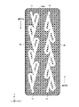
- FIG. 17 is a plan view of the first channel plate and the second channel plate shown in FIG. 16.
- the first channel 15a which is part of the channel 3 shown in FIG. 15b is formed on another plate.
- the pattern of the first channel 15a is indicated by diagonal lines, and the pattern of the second channel 15b is indicated by white.
- the channel switching device 1c has an upper cover plate 22, a first channel plate 23a, a second channel plate 23b and a lower cover plate 24.
- the flow path switching device 1c is configured by laminating the lower lid plate 24, the second flow path plate 23b, the first flow path plate 23a, and the upper lid plate 22 in this order.
- a first channel 15a is formed through the first channel plate 23a.
- a second channel 15b is formed through the second channel plate 23b.
- a relay first circulation port 11a for connecting the upper end of the second flow channel plate 23b to the first circulation port 11 is formed in the first flow channel plate 23a.
- a relay second flow port 12a for connecting the lower end of the second flow channel plate 23b to the second flow port 12 is formed in the first flow channel plate 23a.
- the pattern of each channel of the first channel 15a and the second channel 15b will be described with reference to FIG.
- the first flow path 15a has a plurality of main second linear portions 7b.
- the second flow path 15b has a plurality of main first linear portions 7a and a plurality of sub flow paths 8.
- the second flow path 15b has a connecting portion 10 that connects the sub-flow path 8 closest to the second flow port 12a to the second flow port 12a.
- each of the plurality of main second straight portions 7b of the first channel 15a is arranged at a constant interval between the first flow port 11a and the second flow port 12a. pattern.
- the second channel 15b has a pattern in which the main first linear portions 7a and the sub-channels 8 are alternately arranged.
- the coolant is more likely to flow from the connection portion 10 to the secondary channel 8 than from the connection portion 10 to the main second straight portion 7b.
- the amount of refrigerant that flows from the connection portion 10 to the secondary flow path 8 is greater than the amount of refrigerant that flows from the connection portion 10 to the main second straight portion 7b.
- the coolant flows into the second flow path 15b from the first flow port 11a.
- the coolant flows in the forward direction.
- the refrigerant tries to flow from a position corresponding to the first flow port 11a of the second flow path 15b toward the second flow port 12a (opposite direction of the Y-axis arrow)
- a portion of the refrigerant flows along the main first straight line.
- the rest of the refrigerant flows from the main first straight portion 7a to the main second straight portion 7b of the first channel plate 23a.
- each of the plurality of main second straight portions 7b is arranged at regular intervals, and a plate material is provided between the main first straight portions 7a and the main second straight portions 7b. Even if there is a step in the stacking direction, the coolant can be smoothly circulated in the forward direction.
- the first flow path 15a and the second flow path 15b can be formed in a plate material by press working, mass production can be achieved while suppressing manufacturing costs.
- the second flow path 15b is formed of a single flow path, the refrigerant does not move in the stacking direction of the plate members when the flow direction of the refrigerant is reversed. Therefore, the refrigerant flows more easily through the sub-flow path 8, the resistance in the reverse direction increases, and the check valve effect improves. Thus, even if the main flow path 7 and the sub-flow path 8 are divided into two plates, the reverse resistance can be increased while maintaining the forward resistance at a low value.
- the pattern of a part of the main first linear portion 7a may overlap the pattern of the main second linear portion 7b when viewed in the stacking direction of the first flow path plate 23a and the second flow path plate 23b.
- the forward resistance and the reverse resistance can be set by adjusting the size of the overlapping area S between the pattern of the main first straight portion 7a and the pattern of the main second straight portion 7b.
- Embodiments 1 to 3 the case where the anisotropic flow path 5 is formed in one plate has been described, but the flow path switching device 1c of Embodiment 4 has the anisotropic flow path 5 consists of multiple plates.
- a part of the anisotropic flow path 5 is a plate different from the plate in which one or both of the first flow port 11 and the second flow port 12 are formed, among the plurality of plates. is formed in A part of the anisotropic channel 5 is formed on one plate, and the other part of the anisotropic channel 5 is formed on another plate.
- the plate on which the other part of the anisotropic flow path 5 is formed may be the same as the plate on which one or both of the first flow port 11 and the second flow port 12 are formed.
- a part of the anisotropic flow path 5 functioning as a check valve and the other part are formed on separate plates so that the function of the check valve can be ensured.
- Directional resistance can be adjusted.
- the function of the check valve can be ensured, and the flow direction of the refrigerant can be automatically switched.
- the flow path switching device 1c of the fourth embodiment is not provided with a movable part such as a valve body, it is possible to suppress the generation of abnormal noise due to the sliding motion, as in the first embodiment.
- Modification 2 A modification of the channel switching device of the fourth embodiment will be described.
- 18 is a perspective view for explaining the configuration of a flow path switching device of Modification 2 in Embodiment 3.
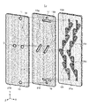
- FIG. 19 is an exploded perspective view showing a configuration example of a flow path switching device of Modification 2.
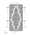
- FIG. 20 is a plan view of the first channel plate and the second channel plate shown in FIG. 19.
- FIG. 20 is a plan view of the first channel plate and the second channel plate shown in FIG. 19.
- the first channel 15a which is part of the channel 3 shown in FIG. 15b is formed on another plate.
- the pattern of the first flow path 15a is indicated by diagonal lines, and the pattern of the second flow path 15b is indicated by white.
- the flow path switching device 1d of Modification 2 has a configuration in which the patterns of the first flow paths 15a and the second flow paths 15b are different from those of the flow path switching device 1c described with reference to FIGS. be.
- the channel switching device 1d has an upper cover plate 22, a first channel plate 23a, a second channel plate 23b and a lower cover plate 24.
- the flow path switching device 1d is configured by laminating the lower lid plate 24, the second flow path plate 23b, the first flow path plate 23a, and the upper lid plate 22 in this order.
- a first channel 15a is formed through the first channel plate 23a.
- a second channel 15b is formed through the second channel plate 23b.
- the pattern of each channel of the first channel 15a and the second channel 15b will be described with reference to FIG.
- the first flow path 15a has a portion other than a part of the plurality of main flow paths 7 .
- the second flow path 15b has a plurality of sub-flow paths 8 and a portion of a plurality of main flow paths 7.
- the first flow path 15a has a pattern in which one main second linear portion 7b is connected in series to five main flow paths 7 .
- the part of the plurality of main flow paths 7 is the main first straight portion 7a connecting the first flow port 11a and the main second straight portion 7b.
- a part of the plurality of main flow paths 7 is not limited to the main first straight portion 7a connecting the first flow port 11a and the main second straight portion 7b.
- the connecting portion 10 is formed in the second flow path 15b instead of the first flow path 15a.
- the first flow port 11a and the second flow port 12a are not connected by one flow channel, and part of the middle of the first flow channel 15a is the second flow channel. It is formed in the flow path 15b.
- the second flow path 15b has a pattern in which each of the plurality of sub-flow paths 8 is arranged at regular intervals between the first flow port 11a and the second flow port 12a. be.
- the sub-channel 8 closest to the first flow port 11a is connected to the first flow port 11a via the main first straight portion 7a.
- the sub-channel 8 closest to the second flow port 12a is connected to the second flow port 12a through the connecting portion 10.
- the coolant flows more easily from the connecting portion 10 to the sub-channel 8 than from the connecting portion 10 to the main channel 7 .
- the amount of refrigerant flowing from the connection portion 10 to the sub-flow passage 8 is greater than the amount of refrigerant flowing from the connection portion 10 to the main flow passage 7 .
- the coolant flows into the second flow path 15b from the first flow port 11a.
- the coolant flows in the forward direction.
- the refrigerant tries to flow from a position corresponding to the first flow port 11a of the second flow path 15b toward the second flow port 12a (opposite direction of the Y-axis arrow)
- a portion of the refrigerant flows along the main first straight line.
- the rest of the refrigerant flows from the main first straight portion 7a to the main second straight portion 7b of the first channel plate 23a.
- the refrigerant flowing through the main second straight portion 7b of the first flow path plate 23a flows through the five main flow paths 7 formed in series in the same first flow path plate 23a. Therefore, as shown in FIG. 17, the coolant can flow through the first channel 15a at once. Therefore, even if a part of the plurality of main flow paths 7 is formed in the second flow path plate 23b, the coolant can be smoothly circulated in the forward direction.
- the first flow path 15a and the second flow path 15b can be formed in a plate material by press working, so mass production can be achieved while suppressing manufacturing costs. Further, when the flow direction of the coolant is the opposite direction, the coolant does not move in the stacking direction of the plate members, so that the check valve effect is improved as in the flow path switching device 1c. Furthermore, the flow switching device 1d of Modification 2 can reduce the forward resistance as compared with the flow switching device 1c.
- the flow paths can be formed by press molding. As a result, it is possible to improve the productivity of the channel switching device while suppressing the manufacturing cost.
- the channel 3 is formed by being divided into two channel plates. This increases the degree of freedom in designing one or both of the channel length and width of each channel plate.
- the channel width of one of the two channel plates may be larger than the channel width of the other channel plate.
- the forward and reverse flow balance can be adjusted by designing the channel length and width of each channel plate.
- the flow path switching device it is possible to select a specification that enhances the check valve effect and a specification that lowers the check valve effect, so that flow path switching devices with various specifications can be manufactured.
- the flow path switching device of the fourth embodiment is provided in the refrigeration cycle apparatus, the flow path of one flow path plate of the two flow path plates is common to all models of the refrigeration cycle apparatus.
- the channel width may be adjusted by the other channel plate.
- one flow path plate is common to all models of the refrigeration cycle apparatus, so it is mass-produced, and the other flow path plate is manufactured according to the model of the refrigeration cycle apparatus, thereby meeting the needs of the refrigeration cycle apparatus.
- a channel switching device can be manufactured quickly.
- Embodiment 5 relates to a refrigeration cycle apparatus provided with the flow path switching device described in the third embodiment.
- the case of the flow path switching device 1b shown in FIG. 10 will be described, but the first plate 21a may have the configuration shown in FIG.
- the same reference numerals are assigned to the same configurations as those described in the first to fourth embodiments, and detailed description thereof will be omitted.
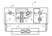
- FIG. 21 is a refrigerant circuit diagram showing a configuration example of a refrigeration cycle apparatus according to Embodiment 5.
- FIG. The refrigeration cycle apparatus 100 has a heat source side unit 60 and a load side unit 70 .
- the heat source side unit 60 and the load side unit 70 are connected by a gas extension pipe 73 and a liquid extension pipe 74 .
- the heat source side unit 60 has a compressor 31 , a four-way valve 36 , a flow path switching device 1 b , a heat source side heat exchanger 61 and an expansion valve 33 .
- the load side unit 70 has a load side heat exchanger 71 .
- the compressor 31, the heat source side heat exchanger 61, the expansion valve 33, and the load side heat exchanger 71 are connected by refrigerant piping to form a refrigerant circuit 55 in which the refrigerant circulates.
- the compressor 31 , the four-way valve 36 and the expansion valve 33 are connected to a controller (not shown) that controls the refrigeration cycle circuit of the refrigeration cycle device 100 .
- the heat source side heat exchanger 61 has a main heat exchanger 61a and an auxiliary heat exchanger 61b.
- the four-way valve 36 is connected to the refrigerant discharge port and the refrigerant discharge port of the compressor 31 , the gas extension pipe 73 , and the refrigerant pipe 51 .
- the fourth flow port 14 is connected to the refrigerant pipe 51, the first flow port 11 and the second flow port 12 are connected via the refrigerant pipe 53, and the third flow port 13 is connected.
- the refrigerant pipe 53 is provided with a main heat exchanger 61a
- the refrigerant pipe 52 is provided with an auxiliary heat exchanger 61b.
- a refrigerant circuit 55 including a heat source side heat exchanger 61 divided into a main heat exchanger 61a and an auxiliary heat exchanger 61b is provided with a flow switching device 1b as a refrigerant device.
- FIG. 21 is a diagram showing the flow direction of the refrigerant flowing through the channel switching device during the cooling operation of the refrigeration cycle apparatus shown in FIG. 21 .
- the four-way valve 36 switches the flow direction of the refrigerant so that the refrigerant discharged from the compressor 31 flows to the heat source side heat exchanger 61 .
- Refrigerant discharged from the compressor 31 flows through the refrigerant pipe 51 into the fourth flow port 14 of the flow path switching device 1b.
- the refrigerant that has flowed into the fourth flow port 14 flows in the forward direction through the fourth anisotropic flow path array 16 d and flows out from the second flow port 12 to the refrigerant pipe 53 .
- the refrigerant flowing through the refrigerant pipe 53 flows through the main heat exchanger 61a. After exchanging heat with the outside air in the main heat exchanger 61a, the refrigerant flows into the first flow port 11 of the flow path switching device 1b.
- the coolant does not flow into the third anisotropic flow channel array 16c. , in the forward direction of the first anisotropic flow path array 16 a , and flows out from the third flow port 13 to the refrigerant pipe 52 .
- the refrigerant flowing through the refrigerant pipe 52 flows through the auxiliary heat exchanger 61b.
- the refrigerant flows into the expansion valve 33 after exchanging heat with the outside air in the auxiliary heat exchanger 61b.
- the refrigerant flowing into the expansion valve 33 is expanded by the expansion valve 33 and flows into the load side unit 70 via the liquid extension pipe 74 .
- the refrigerant flowing into the load-side unit 70 exchanges heat with the air in the air-conditioned space in the load-side heat exchanger 71, thereby cooling the air in the air-conditioned space.
- the refrigerant after heat exchange returns to the heat source side unit 60 via the gas extension pipe 73 .
- the refrigerant that has returned to the heat source side unit 60 returns to the compressor 31 via the four-way valve 36 and is sucked into the compressor 31 .
- FIG. 23 is a diagram showing the direction of refrigerant flow when the refrigeration cycle apparatus shown in FIG. 21 performs heating operation.
- the flow direction of the coolant is indicated by dashed arrows, and the flow of air is indicated by white arrows.
- the heat source side heat exchanger 61 functions as an evaporator.
- FIG. 24 is a diagram showing the flow direction of the refrigerant flowing through the flow path switching device during the heating operation of the refrigeration cycle apparatus shown in FIG. 21 .
- the four-way valve 36 switches the refrigerant flow direction so that the refrigerant discharged from the compressor 31 flows to the load-side heat exchanger 71 .
- Refrigerant discharged from the compressor 31 flows into the load side unit 70 via the four-way valve 36 and the gas extension pipe 73 .
- the refrigerant flowing into the load-side unit 70 exchanges heat with the air in the air-conditioned space in the load-side heat exchanger 71, thereby warming the air in the air-conditioned space.
- the refrigerant returns to the heat source side unit 60 via the liquid extension pipe 74 .
- the refrigerant returned to the heat source side unit 60 is expanded by the expansion valve 33 .
- the refrigerant expanded by the expansion valve 33 flows through the auxiliary heat exchanger 61 b via the refrigerant pipe 52 . After exchanging heat with the outside air in the auxiliary heat exchanger 61b, the refrigerant flows into the third flow port 13 of the flow path switching device 1b.
- the refrigerant that has flowed into the third flow port 13 flows forward through the second anisotropic flow path array 16 b and flows out from the second flow port 12 to the refrigerant pipe 53 .
- the refrigerant flowing through the refrigerant pipe 53 flows through the main heat exchanger 61a. After exchanging heat with the outside air in the main heat exchanger 61a, the refrigerant flows into the first flow port 11 of the flow path switching device 1b.
- the refrigerant since the pressure of the refrigerant is higher at the third flow port 13 than at the first flow port 11, the refrigerant does not flow into the first anisotropic flow channel array 16a. , in the forward direction of the third anisotropic flow path array 16 c , and flows out from the fourth flow port 14 to the refrigerant pipe 51 .
- the refrigerant flowing through the refrigerant pipe 51 returns to the compressor 31 via the four-way valve 36 and is sucked into the compressor 31 .
- the main heat exchanger 61a has a structure in which the refrigerant flows in opposite directions.
- FIG. 25 is an external perspective view showing a configuration example of a heat source side heat exchanger for explaining counterflow.
- the heat source side heat exchanger 80 includes a first heat exchanger 80a and a second heat exchanger 80b, a first header 81 provided at the refrigerant inlet/outlet of the first heat exchanger 80a, and a refrigerant of the second heat exchanger 80b. It has a second header 82 provided at the entrance and a relay portion 83 .
- the relay portion 83 serves to relay the flow of refrigerant between the first heat exchanger 80a and the second heat exchanger 80b.
- the direction in which the air flows is indicated by a diagonal arrow 85 .
- the heat source side heat exchanger 80 shown in FIG. 25 functions as an evaporator
- the refrigerant that flows in from the first header 81 flows through the first heat exchanger 80a on the leeward side, and then passes through the relay section 83 to reach the wind. It flows into the upper second heat exchanger 80b. After that, the refrigerant flows out from the heat source side heat exchanger 80 via the second header 82 .
- the direction of refrigerant flow in the first heat exchanger 80a and the direction of refrigerant flow in the second heat exchanger 80b are opposed to the direction of air flow.
- FIG. 26 is a diagram showing an example of air temperature distribution when the heat source side heat exchanger shown in FIG. 25 functions as an evaporator.
- FIG. 26 is an image diagram showing the temperature distributions of the refrigerant and air for parallel flow and counterflow, respectively.
- the coolant temperature is indicated by a dashed line
- the air temperature is indicated by a solid line.
- the evaporator when configured to have a counter flow, it is easier to ensure a temperature difference between the refrigerant temperature and the air temperature on the refrigerant outlet side of the heat source side heat exchanger 80 compared to a parallel flow.
- the refrigerant is a mixed refrigerant having a temperature gradient, the refrigerant temperature rises even in the vapor-liquid two-phase refrigerant state during the evaporation process.
- the refrigerant is a mixed refrigerant, it is easier to ensure the temperature difference between the refrigerant temperature and the air temperature on the refrigerant outlet side of the heat source side heat exchanger 80 compared to the parallel flow, so the heat transfer performance is improved.
- the main heat exchanger 61a shown in FIG. 21 is the heat source side heat exchanger 80 shown in FIG. 25, and the heat source side heat exchanger 80 shown in FIG.
- the flow direction is the same as that described with reference to FIG. Therefore, the main heat exchanger 61a has a counterflow configuration in both cases of functioning as a condenser and functioning as an evaporator. As a result, the heat transfer performance of the main heat exchanger 61a is improved in both the heating operation and the cooling operation.
- the flow switching device 1b is applied to the heat source side heat exchanger 61, but the flow switching device 1b may be applied to the load side heat exchanger 71. Also, the heat source side heat exchanger 61 may not include the auxiliary heat exchanger 61b.
- the fifth embodiment In the case of the conventional check valve bridge circuit, installation space is required for the movable part in which the valve body operates. Therefore, when the heat exchanger has a main heat exchanger and an auxiliary heat exchanger, providing a check valve bridge circuit between the main heat exchanger and the auxiliary heat exchanger reduces the size of the heat exchanger. There is a need to.
- the flow path switching device 1b since the flow path switching device 1b has a structure in which the flow paths are formed in a plurality of laminated plate materials, the installation space is smaller than that of the conventional check valve bridge circuit. can be made smaller. As a result, the size of the heat exchanger can be increased.
- 1, 1a to 1d channel switching device 2a first plate, 2b second plate, 3 channel, 3a, 3b end, 5 anisotropic channel, 6a first anisotropic channel row, 6b Second anisotropic channel array, 7 main channel, 7a main first straight portion, 7b main second straight portion, 8 sub-channel, 8a sub-first straight portion, 8b sub-second straight portion, 8c curved portion, 9a first confluence, 9b second confluence, 10 connection part, 11, 11a first flow port, 12, 12a second flow port, 13 third flow port, 14 fourth flow port, 15a th 1 channel, 15b second channel, 16a first anisotropic channel row, 16b second anisotropic channel row, 16c third anisotropic channel row, 16d fourth anisotropic channel row, 17 first connection channel, 18a first auxiliary channel, 18b second auxiliary channel, 19 second connection channel, 20a first plate, 20b second plate, 21a first plate, 21b second Plate 21c Third plate 22 Upper cover plate 23a First channel plate 23b Second
Landscapes
- Engineering & Computer Science (AREA)
- Physics & Mathematics (AREA)
- Mechanical Engineering (AREA)
- Thermal Sciences (AREA)
- General Engineering & Computer Science (AREA)
- Fluid Mechanics (AREA)
- Multiple-Way Valves (AREA)
- Compression-Type Refrigeration Machines With Reversible Cycles (AREA)
Abstract
Description
本実施の形態1の流路切替装置の構成を説明する。図1は、実施の形態1に係る流路切替装置の一構成例を示す分解斜視図である。流路切替装置1は、第1の板2aと、第2の板2bとが積層された構成である。第1の板2aには、溝状の流路3が形成されている。流路3は、積層される第1の板2aおよび第2の板2bのそれぞれの面に平行に配置される。第2の板2bには、冷媒の流通口となる第1の流通口11および第2の流通口12が設けられている。第1の板2aに第2の板2bが重ね合わされることで、流路3が形成される。流路3の端部3aおよび3bの2つの端部のうち、端部3aが第1の流通口11に位置し、端部3bが第2の流通口12に位置する。
本実施の形態2は、実施の形態1で説明した異方性流路列が複数設けられたものである。本実施の形態2は、2つの異方性流路列が設けられる場合である。本実施の形態2においては、実施の形態1で説明した構成と同一の構成に同一の符号を付し、その詳細な説明を省略する。
本実施の形態3は、4つの異方性流路列を有するものである。本実施の形態3では、4つの異方性流路列がブリッジ回路を構成する場合を説明する。本実施の形態3においては、実施の形態1および2で説明した構成と同一の構成に同一の符号を付し、その詳細な説明を省略する。
本実施の形態3の流路切替装置1bの変形例を説明する。図14は、実施の形態3に係る流路切替装置において、変形例1の第1の板の一構成例を示す平面図である。順方向を矢印で示す。第1の流通口11と第2の流通口12とを通る仮想線VLを考える。仮想線VLを基準として、第1異方性流路列16aと第3異方性流路列16cとが線対称に配置されている。また、仮想線VLを基準として、第2異方性流路列16bと第4異方性流路列16dとが線対称に配置されている。
本実施の形態4は、実施の形態1で説明した流路切替装置における流路をプレス加工で製造するものである。本実施の形態4は、実施の形態1で説明した流路切替装置を対象として説明するが、本実施の形態4を、実施の形態2および3で説明した流路切替装置に適用してもよい。本実施の形態4においては、実施の形態1~3で説明した構成と同一の構成に同一の符号を付し、その詳細な説明を省略する。
本実施の形態4の流路切替装置の変形例を説明する。図18は、実施の形態3において、変形例2の流路切替装置の構成を説明するための透視図である。図19は、変形例2の流路切替装置の一構成例を示す分解斜視図である。図20は、図19に示した第1の流路板および第2の流路板の平面図である。
本実施の形態5は、実施の形態3で説明した流路切替装置が設けられた冷凍サイクル装置に関するものである。本実施の形態5においては、図10に示した流路切替装置1bの場合で説明するが、第1の板21aが図14に示した構成であってもよい。本実施の形態5においては、実施の形態1~4で説明した構成と同一の構成に同一の符号を付し、その詳細な説明を省略する。
Claims (15)
- 冷凍サイクル装置に設けられ、複数の板で構成された流路切替装置であって、
第1の流通口、第2の流通口および前記第1の流通口と前記第2の流通口とを接続する流路を有し、
前記流路は、
前記第1の流通口から前記第2の流通口への冷媒流通方向である順方向の冷媒の流動抵抗である順方向抵抗と、前記第2の流通口から前記第1の流通口への冷媒流通方向である逆方向の前記冷媒の流動抵抗である逆方向抵抗とが異なる異方性流路を有し、
前記異方性流路の一部が、前記複数の板のうち、前記第1の流通口および前記第2の流通口の一方または両方が形成された板とは異なる板に形成されている、
流路切替装置。 - 前記異方性流路は、
前記第1の流通口から流入する前記冷媒の一部が分流する主流路と、
前記第1の流通口から流入する前記冷媒のうち、前記一部の冷媒を除く残りの冷媒が流入し、前記残りの冷媒を、前記主流路を流通する前記一部の冷媒に合流させる副流路と、を有し、
前記第2の流通口から前記主流路に分流する冷媒の流通が、前記副流路と前記主流路との合流点において、前記第2の流通口から前記副流路に分流する冷媒によって妨げられる、
請求項1に記載の流路切替装置。 - 前記異方性流路は、テスラバルブ構造である、
請求項2に記載の流路切替装置。 - 前記複数の板のうち、少なくとも1枚の板に、1つまたは複数の前記異方性流路が直列に接続される接続流路である第1異方性流路列と、前記第1異方性流路列とは異なる前記接続流路である第2異方性流路列とが形成され、
前記第1異方性流路列および前記第2異方性流路列は、前記第1異方性流路列の順方向と前記第2異方性流路列の順方向とが対向するように並列に形成されている、
請求項2または3に記載の流路切替装置。 - 前記複数の板のうち、少なくとも1枚の板に、1つまたは複数の前記異方性流路が直列に接続される接続流路である第1異方性流路列と、前記第1異方性流路列と互いに異なる3つの前記接続流路である第2異方性流路列、第3異方性流路列および第4異方性流路列とが形成され、
前記第1異方性流路列、前記第2異方性流路列、前記第3異方性流路列および前記第4異方性流路列は、ブリッジ回路を構成する、
請求項2または3に記載の流路切替装置。 - 前記複数の板のうち、前記第1の流通口および前記第2の流通口の一方または両方が形成された板と同一の板または異なる板に第3の流通口および第4の流通口が形成され、
前記第1異方性流路列の一方の端部と前記第3異方性流路列の一方の端部とが前記第1の流通口に接続され、
前記第2異方性流路列の一方の端部と前記第4異方性流路列の一方の端部とが前記第2の流通口に接続され、
前記第1異方性流路列の他方の端部と前記第2異方性流路列の他方の端部とが前記第3の流通口に接続され、
前記第3異方性流路列の他方の端部と前記第4異方性流路列の他方の端部とが前記第4の流通口に接続され、
前記第1異方性流路列および前記第2異方性流路列は前記第1の流通口から前記第2の流通口に前記順方向に接続され、
前記第3異方性流路列および前記第4異方性流路列は前記第1の流通口から前記第2の流通口に前記順方向に接続されている、
請求項5に記載の流路切替装置。 - 前記少なくとも1枚の板において、前記第1の流通口と前記第2の流通口とを通る仮想線を基準として、前記第1異方性流路列と前記第3異方性流路列とが線対称に形成され、前記第2異方性流路列と前記第4異方性流路列とが線対称に形成されている、
請求項6に記載の流路切替装置。 - 前記第1異方性流路列と前記第3異方性流路列とが平行に前記少なくとも1枚の板に形成され、
前記第2異方性流路列と前記第4異方性流路列とが平行に前記少なくとも1枚の板に形成されている、
請求項6に記載の流路切替装置。 - 前記第3の流通口と、前記第1異方性流路列の他方の端部および前記第2異方性流路列の他方の端部とを接続する第1補助流路と、前記第4の流通口と、前記第3異方性流路列の他方の端部および前記第4異方性流路列の他方の端部とを接続する第2補助流路とが前記少なくとも1枚の板に形成され、
前記第1補助流路は、前記第1異方性流路列において、前記第1補助流路に最も近くに位置する前記異方性流路の前記主流路と平行な方向に延び、
前記第2補助流路は、前記第4異方性流路列において、前記第2補助流路に最も近くに位置する前記異方性流路の前記主流路と平行な方向に延びる、
請求項8に記載の流路切替装置。 - 複数の前記異方性流路の一部は、前記複数の板のうち、前記少なくとも1枚の板に溝状に形成されている、
請求項4~9のいずれか1項に記載の流路切替装置。 - 複数の前記主流路および前記副流路は、前記複数の板のうち、少なくとも2枚の板に形成され、
前記複数の主流路は、一部を除いて、前記少なくとも2枚の板のうち、1枚の板である第1の流路板に貫通して形成され、
前記複数の副流路と前記複数の主流路の前記一部とが、前記少なくとも2枚の板のうち、前記第1の流路板とは異なる板である第2の流路板に貫通して形成されている、
請求項4~9のいずれか1項に記載の流路切替装置。 - 前記主流路は、
直線状の主第1直線部と、
前記主第1直線部と同じ直線上に位置する直線状の主第2直線部と、を有し、
複数の前記主流路および前記副流路は、前記複数の板のうち、少なくとも2枚の板に形成され、
前記複数の主第2直線部は、前記少なくとも2枚の板のうち、1枚の板である第1の流路板に貫通して形成され、
前記複数の主第1直線部および前記複数の副流路は、前記少なくとも2枚の板のうち、前記第1の流路板とは異なる板である第2の流路板に貫通して形成されている、
請求項4~9のいずれか1項に記載の流路切替装置。 - 前記第1の流路板および前記第2の流路板が積層された状態の積層方向視において、前記第2の流路板に形成される前記主第1直線部のパターンの一部が、前記第1の流路板に形成される前記主第2直線部のパターンと重複している、
請求項12に記載の流路切替装置。 - 圧縮機を含む冷媒回路と、
前記冷媒回路に設けられ、請求項1~13のいずれか1項に記載の流路切替装置と、
を有する冷凍サイクル装置。 - 熱交換器を含む冷媒回路と、
前記冷媒回路に設けられ、請求項6~9のいずれか1項に記載の流路切替装置と、
前記流路切替装置の前記第1の流通口と前記第2の流通口とを接続する冷媒配管と、
を有し、
前記熱交換器が前記冷媒配管に設けられている、
冷凍サイクル装置。
Priority Applications (4)
| Application Number | Priority Date | Filing Date | Title |
|---|---|---|---|
| PCT/JP2021/023175 WO2022264398A1 (ja) | 2021-06-18 | 2021-06-18 | 流路切替装置およびそれが設けられた冷凍サイクル装置 |
| CN202180099136.0A CN117460922A (zh) | 2021-06-18 | 2021-06-18 | 流路切换装置和设置有该流路切换装置的制冷循环装置 |
| US18/554,230 US20240183594A1 (en) | 2021-06-18 | 2021-06-18 | Flow switching device and refrigeration cycle apparatus including the same |
| JP2023528910A JPWO2022264398A1 (ja) | 2021-06-18 | 2021-06-18 |
Applications Claiming Priority (1)
| Application Number | Priority Date | Filing Date | Title |
|---|---|---|---|
| PCT/JP2021/023175 WO2022264398A1 (ja) | 2021-06-18 | 2021-06-18 | 流路切替装置およびそれが設けられた冷凍サイクル装置 |
Publications (1)
| Publication Number | Publication Date |
|---|---|
| WO2022264398A1 true WO2022264398A1 (ja) | 2022-12-22 |
Family
ID=84526987
Family Applications (1)
| Application Number | Title | Priority Date | Filing Date |
|---|---|---|---|
| PCT/JP2021/023175 Ceased WO2022264398A1 (ja) | 2021-06-18 | 2021-06-18 | 流路切替装置およびそれが設けられた冷凍サイクル装置 |
Country Status (4)
| Country | Link |
|---|---|
| US (1) | US20240183594A1 (ja) |
| JP (1) | JPWO2022264398A1 (ja) |
| CN (1) | CN117460922A (ja) |
| WO (1) | WO2022264398A1 (ja) |
Citations (3)
| Publication number | Priority date | Publication date | Assignee | Title |
|---|---|---|---|---|
| WO2017042866A1 (ja) * | 2015-09-07 | 2017-03-16 | 三菱電機株式会社 | 分配器、積層型ヘッダ、熱交換器、及び、空気調和装置 |
| US20190178783A1 (en) * | 2017-12-11 | 2019-06-13 | Honeywell International Inc. | Micro airflow generator for miniature particulate matter sensor module |
| CN110468026A (zh) * | 2019-09-07 | 2019-11-19 | 桂林电子科技大学 | 一种用于光纤光动力细胞操纵的微流芯片 |
Family Cites Families (12)
| Publication number | Priority date | Publication date | Assignee | Title |
|---|---|---|---|---|
| US1329559A (en) * | 1916-02-21 | 1920-02-03 | Tesla Nikola | Valvular conduit |
| US3425433A (en) * | 1966-04-20 | 1969-02-04 | Moore Products Co | Flow control valve |
| SE508435C2 (sv) * | 1993-02-23 | 1998-10-05 | Erik Stemme | Förträngningspump av membranpumptyp |
| JP3321579B2 (ja) * | 1997-03-10 | 2002-09-03 | 日電工業株式会社 | 冷媒整流ユニット及び空気調和機 |
| JP3666274B2 (ja) * | 1998-11-24 | 2005-06-29 | 三菱電機株式会社 | 冷凍サイクル装置及び逆止弁ユニット |
| US20150059718A1 (en) * | 2013-08-30 | 2015-03-05 | GM Global Technology Operations LLC | Engine Crankcase Breathing Passage With Flow Diode |
| EP3307430B1 (en) * | 2015-06-10 | 2020-12-16 | Corning Incorporated | Thermal cross-talk resistant flow reactor |
| JP7096238B2 (ja) * | 2016-10-06 | 2022-07-05 | コーニンクレッカ フィリップス エヌ ヴェ | 極低温熱サイホンの受動流れ方向バイアシング |
| WO2018116413A1 (ja) * | 2016-12-21 | 2018-06-28 | 三菱電機株式会社 | 分配器、熱交換器、及び、冷凍サイクル装置 |
| JP2018119577A (ja) * | 2017-01-24 | 2018-08-02 | 三菱電機株式会社 | 逆止弁ユニット |
| JP2018194197A (ja) * | 2017-05-15 | 2018-12-06 | 富士通株式会社 | ヒートパイプ及び電子機器 |
| US10602638B2 (en) * | 2018-03-01 | 2020-03-24 | Dell Products L.P. | System and method of transferring energy |
-
2021
- 2021-06-18 WO PCT/JP2021/023175 patent/WO2022264398A1/ja not_active Ceased
- 2021-06-18 JP JP2023528910A patent/JPWO2022264398A1/ja not_active Ceased
- 2021-06-18 US US18/554,230 patent/US20240183594A1/en not_active Abandoned
- 2021-06-18 CN CN202180099136.0A patent/CN117460922A/zh active Pending
Patent Citations (3)
| Publication number | Priority date | Publication date | Assignee | Title |
|---|---|---|---|---|
| WO2017042866A1 (ja) * | 2015-09-07 | 2017-03-16 | 三菱電機株式会社 | 分配器、積層型ヘッダ、熱交換器、及び、空気調和装置 |
| US20190178783A1 (en) * | 2017-12-11 | 2019-06-13 | Honeywell International Inc. | Micro airflow generator for miniature particulate matter sensor module |
| CN110468026A (zh) * | 2019-09-07 | 2019-11-19 | 桂林电子科技大学 | 一种用于光纤光动力细胞操纵的微流芯片 |
Also Published As
| Publication number | Publication date |
|---|---|
| CN117460922A (zh) | 2024-01-26 |
| JPWO2022264398A1 (ja) | 2022-12-22 |
| US20240183594A1 (en) | 2024-06-06 |
Similar Documents
| Publication | Publication Date | Title |
|---|---|---|
| CN103348212B (zh) | 热交换器及空调装置 | |
| CN110073154B (zh) | 分配器、热交换器以及制冷循环装置 | |
| JP5195733B2 (ja) | 熱交換器及びこれを備えた冷凍サイクル装置 | |
| JP6005266B2 (ja) | 積層型ヘッダー、熱交換器、及び、空気調和装置 | |
| JP6388716B2 (ja) | 積層型ヘッダ、熱交換器、及び、空気調和装置 | |
| JP6080982B2 (ja) | 積層型ヘッダー、熱交換器、及び、空気調和装置 | |
| JP6138264B2 (ja) | 積層型ヘッダー、熱交換器、及び、空気調和装置 | |
| JP6716016B2 (ja) | 熱交換器およびそれを備えた冷凍サイクル装置 | |
| JP7086279B2 (ja) | 冷媒分配器、熱交換器及び冷凍サイクル装置 | |
| JP5526494B2 (ja) | 冷凍装置 | |
| JP2022044306A (ja) | 積層型ヘッダ、熱交換器、及び冷凍装置 | |
| JP7112164B2 (ja) | 冷媒分配器、熱交換器および空気調和装置 | |
| WO2022264398A1 (ja) | 流路切替装置およびそれが設けられた冷凍サイクル装置 | |
| JP2014074508A (ja) | カスケード熱交換器 | |
| JP7313557B2 (ja) | 冷媒分配器、熱交換器および空気調和装置 | |
| JP2022044417A (ja) | 積層型ヘッダ、熱交換器、及び冷凍装置 | |
| WO2021014892A1 (ja) | 熱交換器 | |
| WO2024089927A1 (ja) | 熱交換器およびこの熱交換器を備えた冷凍サイクル装置 | |
| JP7810916B1 (ja) | 熱交換器、冷凍装置 | |
| JP2026001602A (ja) | 熱交換器、冷凍装置 | |
| JP2021018051A (ja) | 熱交換器 | |
| JP6970360B2 (ja) | 熱交換器及びそれを有するヒートポンプシステム | |
| JP2019021872A (ja) | 積層型熱交換器 | |
| JP2018119577A (ja) | 逆止弁ユニット | |
| KR20250150884A (ko) | 판형 열교환기 |
Legal Events
| Date | Code | Title | Description |
|---|---|---|---|
| 121 | Ep: the epo has been informed by wipo that ep was designated in this application |
Ref document number: 21946073 Country of ref document: EP Kind code of ref document: A1 |
|
| ENP | Entry into the national phase |
Ref document number: 2023528910 Country of ref document: JP Kind code of ref document: A |
|
| WWE | Wipo information: entry into national phase |
Ref document number: 18554230 Country of ref document: US |
|
| WWE | Wipo information: entry into national phase |
Ref document number: 202180099136.0 Country of ref document: CN |
|
| NENP | Non-entry into the national phase |
Ref country code: DE |
|
| 122 | Ep: pct application non-entry in european phase |
Ref document number: 21946073 Country of ref document: EP Kind code of ref document: A1 |