WO2022264229A1 - 端子台装置 - Google Patents
端子台装置 Download PDFInfo
- Publication number
- WO2022264229A1 WO2022264229A1 PCT/JP2021/022566 JP2021022566W WO2022264229A1 WO 2022264229 A1 WO2022264229 A1 WO 2022264229A1 JP 2021022566 W JP2021022566 W JP 2021022566W WO 2022264229 A1 WO2022264229 A1 WO 2022264229A1
- Authority
- WO
- WIPO (PCT)
- Prior art keywords
- cover
- terminal block
- axis direction
- terminal
- insertion hole
- Prior art date
- Legal status (The legal status is an assumption and is not a legal conclusion. Google has not performed a legal analysis and makes no representation as to the accuracy of the status listed.)
- Ceased
Links
Images







Classifications
-
- H—ELECTRICITY
- H01—ELECTRIC ELEMENTS
- H01R—ELECTRICALLY-CONDUCTIVE CONNECTIONS; STRUCTURAL ASSOCIATIONS OF A PLURALITY OF MUTUALLY-INSULATED ELECTRICAL CONNECTING ELEMENTS; COUPLING DEVICES; CURRENT COLLECTORS
- H01R9/00—Structural associations of a plurality of mutually-insulated electrical connecting elements, e.g. terminal strips or terminal blocks; Terminals or binding posts mounted upon a base or in a case; Bases therefor
Definitions
- the present disclosure relates to a terminal block device including a terminal block.
- Patent Literature 1 discloses a terminal block device including a terminal block and a cover.
- a terminal housing chamber for housing a terminal is formed inside the terminal block disclosed in Patent Document 1.
- An electric wire is connected to the terminal.
- Locking holes are formed in the outer peripheral wall of the terminal block so as to allow communication between the terminal receiving chamber and the outside of the terminal block.
- the cover is formed with a terminal pressing plate that can be inserted into the locking hole.
- the present disclosure has been made in view of the above, and an object of the present disclosure is to obtain a terminal block device that allows a cover to contact a terminal while visually confirming the position of the terminal.
- the terminal block device includes a terminal block in which a plurality of insertion holes and a support surface adjacent to the edges of the insertion holes are formed, and a plurality of crimp terminals having an insertion portion to be inserted; and a supported portion disposed outside the insertion hole in a state in which the insertion portion is inserted into the insertion hole and in contact with the support surface; and a support surface of the supported portion. a cover fixed to the terminal block in contact with the surface facing away from the terminal block.
- the terminal block device With the terminal block device according to the present disclosure, it is possible to bring the cover into contact with the terminals while visually confirming the positions of the terminals.
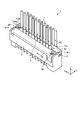
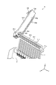
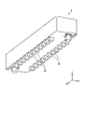
- FIG. 2 is a perspective view showing an assembled state of the terminal block device according to the first embodiment
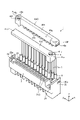
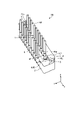
- 1 is an exploded perspective view showing a terminal block device according to a first embodiment
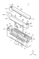
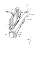
- FIG. FIG. 3 is an exploded perspective view showing the terminal block device according to the first embodiment, and is a view of the terminal block device from an angle different from that in FIG. 2
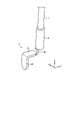
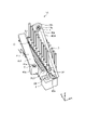
- Partially enlarged perspective view showing the terminal block in Embodiment 1 1 is a perspective view showing a crimp terminal, an electric wire, and an insulating tube according to Embodiment 1
- FIG. 12 is an exploded perspective view showing the terminal block device according to the second embodiment, and is a view of the terminal block device from an angle different from that in FIG. 11;
- FIG. 11 is an exploded perspective view showing the terminal block device according to the third embodiment, showing a state in which the cover is closed;
- FIG. 12 is an exploded perspective view showing the terminal block device according to the third embodiment, showing a state in which the cover is opened; The figure which showed the state which opened the cover of the terminal block apparatus concerning Embodiment 4.
- FIG. 17 is a view showing a state in which the cover of the terminal block device according to the fourth embodiment is opened, and is a view of the terminal block device from an angle different from that in FIG. 16;
- FIG. 11 is a partially enlarged perspective view showing a first rotating shaft and a first bearing portion according to Embodiment 4;
- FIG. 11 is an exploded perspective view showing the terminal block device according to the fifth embodiment, showing a state where the insertion portion of the crimp terminal is not inserted into the insertion hole;
- FIG. 11 is an exploded perspective view showing a terminal block device according to a fifth embodiment, showing a state in which an insertion portion of a crimp terminal is inserted into an insertion hole;
- FIG. 1 is a perspective view showing an assembled state of the terminal block device 1 according to the first embodiment.
- FIG. 2 is an exploded perspective view showing the terminal block device 1 according to the first embodiment.
- FIG. 3 is an exploded perspective view showing the terminal block device 1 according to the first embodiment, and is a view of the terminal block device 1 viewed from an angle different from that in FIG.
- the shape of the terminal block device 1 is not particularly limited, but in this embodiment, it is substantially a rectangular parallelepiped as shown in FIG.
- the terminal block device 1 includes a terminal block 2 , multiple crimp terminals 3 , multiple covers 4 , and multiple fixing members 5 .
- the longitudinal direction of the terminal block device 1 is the X-axis direction
- the lateral direction of the terminal block device 1 is the Y-axis direction
- the height direction of the terminal block device 1 is the Z-axis direction.
- the X-axis direction as the first direction, the Y-axis direction as the second direction, and the Z-axis direction are orthogonal to each other.
- the terminal block 2 is formed in a substantially rectangular parallelepiped shape with the length in the X-axis direction being longer than the length in the Y-axis direction.
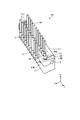
- FIG. 4 is a partially enlarged perspective view showing the terminal block 2 according to Embodiment 1.
- a plurality of insertion holes 20, a plurality of support surfaces 21, and a plurality of shielding walls 22 are formed at one end of the terminal block 2 in the Z-axis direction.
- the insertion holes 20 are arranged in multiple rows in the Y-axis direction. The number of rows of insertion holes 20 is two in this embodiment.
- the insertion holes 20 in each row are spaced apart from each other in the X-axis direction.
- the support surface 21 adjoins the edge of the insertion hole 20 .
- the support surface 21 is a flat surface extending in the X-axis direction and the Y-axis direction.
- the support surface 21 and the opening of the insertion hole 20 are provided side by side in the Y-axis direction.
- One support surface 21 is provided for each insertion hole 20 .
- Rectangular shielding walls 22 are provided between adjacent insertion holes 20 and adjacent support surfaces 21 .
- the shielding wall 22 serves to maintain an electrical insulation distance between adjacent crimp terminals 3 and also serves to guide the crimp terminals 3 when inserting an insertion portion 30 described later into the insertion hole 20 .
- a supported portion 31 of the crimp terminal 3 which will be described later, is fitted between two adjacent shield walls 22 . Note that the shielding wall 22 may be omitted. In this way, one support surface 21 is formed adjacent to the edges of the plurality of insertion holes 20 in each row.
- one first fixing hole 23 and one second support wall 26 are formed at one end of the terminal block 2 in the X-axis direction.
- One second fixing hole 24 and one first support wall 25 are formed at the other end of the terminal block 2 in the X-axis direction.
- the first support wall 25 and the second support wall 26 extend away from one end of the terminal block 2 along the Z-axis direction.
- the first support wall 25 is formed with a rectangular first insertion hole 25a penetrating in the X-axis direction.
- the second support wall 26 is formed with a rectangular second insertion hole 26a penetrating in the X-axis direction.
- the positions of the first fixing hole 23 and the first insertion hole 25a match in the Y-axis direction.
- One row of insertion holes 20 is arranged between the first fixing hole 23 and the first insertion hole 25a.
- the row in which the insertion holes 20 are arranged is referred to as the first row.
- the positions of the second fixing hole 24 and the second insertion hole 26a match in the Y-axis direction.
- the other row of insertion holes 20 is arranged between the second fixing hole 24 and the second insertion hole 26a.
- the row in which the insertion holes 20 are arranged will be referred to as the second row.
- the crimp terminal 3 is a metal member that electrically connects the contactor 6 and the electric wire 7 .
- FIG. 5 is a perspective view showing the crimp terminal 3, the electric wire 7 and the insulating tube 8 according to the first embodiment.
- the crimp terminal 3 includes an insertion portion 30 extending in the Z-axis direction, a supported portion 31 extending in the Y-axis direction from one end of the insertion portion 30 in the Z-axis direction, and the supported portion 31 Among them, it has an insertion portion 30 and a connection portion 32 extending in the Z-axis direction from an end located on the opposite side.
- the crimp terminal 3 is formed by bending a single metal plate.
- the crimp terminal 3 has a crank shape.
- the insertion portion 30 is a plate-like portion that is inserted into the insertion hole 20 .
- the distal end of the insertion portion 30 is formed in a tapered triangular shape.
- the supported portion 31 is a flat portion extending in the X-axis direction and the Y-axis direction.
- the supported portion 31 is formed continuously with the insertion portion 30 .
- the connecting portion 32 is a plate-like portion that is connected to the electric wire 7 .
- the connecting portion 32 is formed continuously with the supported portion 31 .
- a connecting portion between the connecting portion 32 and the electric wire 7 is covered with a cylindrical insulating tube 8 .
- the cover 4 is a member fixed to the terminal block 2 by contacting the supported portions 31 of the plurality of crimp terminals 3 .
- a cover 4 covers one end of the terminal block 2 .
- Two covers 4 are arranged side by side in the Y-axis direction. In the following description, when distinguishing between the two covers 4 , one cover 4 is referred to as the first cover 40 and the other cover 4 is referred to as the second cover 41 .
- the first cover 40 contacts each of the supported portions 31 of the crimp terminals 3 in the first row.
- the first cover 40 has a first boss portion 40a and a first arm portion 40b linearly extending from the first boss portion 40a along the X-axis direction.
- the first boss portion 40a is a substantially quadrangular prism-shaped portion.
- a first insertion hole 40c is formed through the first boss portion 40a in the Z-axis direction. The shape of the first insertion hole 40c is circular.
- the first arm portion 40b is a generally rectangular wall-shaped portion.
- a plurality of first pressing portions 40d projecting toward the terminal block 2 are formed on the surface of the first arm portion 40b facing the terminal block 2.
- the first pressing portion 40 d is a portion that presses the supported portion 31 .
- a tip surface of the first pressing portion 40d is a flat surface extending in the X-axis direction and the Y-axis direction.
- the plurality of first pressing portions 40d are arranged at the same intervals as the supported portions 31 and are spaced apart from each other in the X-axis direction.
- a rectangular plate-like first protrusion 40e protrudes from a surface of the first arm portion 40b located on the opposite side of the first boss portion 40a in the X-axis direction.
- the surface of the first arm portion 40b facing the second cover 41 has two contact surfaces 40f capable of contacting the second cover 41, and a contact surface disposed between the two contact surfaces 40f.
- a notch portion 40g is formed so as to be separated from the second cover 41 when 40f is in contact with the second cover 41 .
- a passage hole 42 through which the electric wire 7 can pass is formed at a portion corresponding to the notch 40g.
- the shape of the through hole 42 is rectangular.
- the wires 7 are arranged in two rows in the Y-axis direction, and the wire 7 in the second row passes through the passage hole 42 .
- the wires 7 in the first row are arranged on the side opposite to the passage hole 42 with the first cover 40 interposed therebetween.
- the second cover 41 contacts each of the supported portions 31 of the crimp terminals 3 in the second row.
- the second cover 41 has a second boss portion 41a and a second arm portion 41b linearly extending from the second boss portion 41a along the X-axis direction.
- the second boss portion 41a is a substantially quadrangular prism-shaped portion.
- the first boss portion 40a and the second boss portion 41a are arranged opposite to each other in the X-axis direction.
- a second insertion hole 41c is formed through the second boss portion 41a in the Z-axis direction.
- the shape of the second insertion hole 41c is circular.
- the second arm portion 41b is a generally rectangular wall-shaped portion.
- a plurality of second pressing portions 41d projecting toward the terminal block 2 are formed on the surface of the second arm portion 41b facing the terminal block 2.
- the second pressing portion 41 d is a portion that presses the supported portion 31 .
- a tip surface of the second pressing portion 41d is a flat surface extending in the X-axis direction and the Y-axis direction.
- the plurality of second pressing portions 41d are arranged at the same intervals as the supported portions 31 and are spaced apart from each other in the X-axis direction.
- a rectangular plate-shaped second protrusion 41e protrudes from a surface of the second arm portion 41b located on the opposite side of the second boss portion 41a in the X-axis direction.
- the fixing member 5 shown in FIG. 1 is a member that fixes the cover 4 to the terminal block 2 so that it cannot move.
- the fixing member 5 is a screw in this embodiment, but is not particularly limited as long as the cover 4 can be fixed to the terminal block 2 so as not to move.
- the fixing member 5 may be, for example, a spring pin.
- one fixing member 5 is inserted into the first insertion hole 40c and the first fixing hole 23.
- One fixing member 5 is inserted into the second insertion hole 41 c and the second fixing hole 24 .
- the crimp terminals 3 are inserted into the insertion holes 20 one by one.
- the first 1 cover 40 is fixed to the terminal block 2 .
- the second protrusion 41e of the second cover 41 is inserted into the second insertion hole 26a, and the fixing member is inserted into the second insertion hole 41c and the second fixing hole 24.
- the second cover 41 is fixed to the terminal block 2 by screwing the terminal block 5 . That is, one end of each cover 4 in the X-axis direction is fitted to the terminal block 2 , and the other end of each cover 4 in the X-axis direction is fixed to the terminal block 2 by a fixing member 5 . .
- FIG. 6 is a cross-sectional view along line VI-VI shown in FIG. 6 illustrates a state in which the insertion portion 30 is inserted into the insertion hole 20 and the cover 4 is fixed to the terminal block 2.
- FIG. Inside the insertion hole 20 , a contactor 6 that contacts the insertion portion 30 of the crimp terminal 3 is provided.
- the supported portion 31 is arranged outside the insertion hole 20 and is in contact with the support surface 21 while the insertion portion 30 is inserted into the insertion hole 20 .
- the supported portion 31 is in surface contact with the supporting surface 21 . At least a portion of the supported portion 31 should be in contact with the supporting surface 21 .
- the supported portion 31 and the connection portion 32 are exposed to the outside of the insertion hole 20 .
- the cover 4 is in contact with the surface of the supported portion 31 facing away from the supporting surface 21 .
- Each supported portion 31 is sandwiched between the support surface 21 of the terminal block 2 and the cover 4 while the cover 4 is fixed to the terminal block 2 .
- a force is exerted to pull the cover 4 toward the terminal block 2 , so the cover 4 is pressed against each supported portion 31 and each supported portion 31 is pressed toward the terminal block 2 .
- FIG. 6 shows only a state in which the cover 4 is in contact with one supported portion 31, it actually contacts a plurality of supported portions 31 at the same time.
- the first pressing portion 40 d and the second pressing portion 41 d of the cover 4 cover the insertion hole 20 . This structure makes it difficult for dirt, dust, etc. to enter the insertion hole 20 .
- the terminal block device 1 includes a terminal block 2, a plurality of crimp terminals 3, and a cover 4, as shown in FIG.
- the terminal block 2 is formed with a plurality of insertion holes 20 and a support surface 21 adjacent to the edges of the insertion holes 20 .
- each crimp terminal 3 includes an insertion portion 30 inserted into an insertion hole 20 and a supporting surface 21 disposed outside the insertion hole 20 with the insertion portion 30 inserted into the insertion hole 20 . and a supported portion 31 in contact with the .
- the cover 4 is fixed to the terminal block 2 in contact with the surface of the supported portion 31 facing away from the supporting surface 21 .
- the supported portion 31 of the crimp terminal 3 and the cover 4 are brought into contact with each other outside the terminal block 2 , and the cover 4 is fixed to the terminal block 2 , thereby preventing the crimp terminal 3 from moving on the terminal block 2 .
- the cover 4 can be brought into contact with the crimp terminal 3 while visually confirming the position of the crimp terminal 3 .
- the plurality of crimp terminals 3 can be collectively fixed to the terminal block 2, so that the wiring work of the electric wire 7 is facilitated.
- the cover 4 from the terminal block 2
- the fixed state between the plurality of crimp terminals 3 and the terminal block 2 can be released collectively, so maintenance work for the wires 7 can be facilitated.
- the portion of the crimp terminal 3 that is exposed to the outside of the insertion hole 20 can be grasped and the crimp terminal 3 can be easily inserted into and pulled out of the insertion hole 20, the wiring work and maintenance work of the electric wire 7 are further facilitated. .
- the terminal block device 1 includes a fixing member 5 that fixes the cover 4 to the terminal block 2 so that the cover 4 is fixed to the terminal block 2.
- Each supported portion 31 is sandwiched between the support surface 21 of the terminal block 2 and the cover 4 . This facilitates attachment and detachment of the cover 4 with respect to the terminal block 2, thereby reducing the workload of the operator.
- the connection strength of the crimp terminal 3 that is, the tensile strength to resist the tensile force of the electric wire 7 is increased. can be enhanced.
- the insertion holes 20 are spaced apart from each other in the X-axis direction.
- One end of the cover 4 in the X-axis direction is inserted into the insertion holes 25 a and 26 a of the terminal block 2 , and the other end of the cover 4 in the X-axis direction is fixed to the terminal block 2 by a fixing member 5 .
- the number of locations fixed by the fixing member 5 can be reduced, so attachment and detachment of the cover 4 with respect to the terminal block 2 is further facilitated. Therefore, the work load of the worker can be further reduced.
- the cover 4 since the cover 4 is fixed to the terminal block 2 with one fixing member 5, the cover 4 can be removed from the terminal block 2 only by removing the one fixing member 5. maintenance work becomes easier.
- the wire 7 can be extended in the Z-axis direction by inserting the crimp terminal 3 into the insertion hole 20 from the Z-axis direction. Even if they are arranged, interference between the electric wires 7 can be avoided.
- the first cover 40 has a contact surface 40 f that can contact the second cover 41 and a contact surface 40 f that contacts the second cover 41 when the contact surface 40 f contacts the second cover 41 . 2 is formed with a notch 40g that is separated from the cover 41. As shown in FIG. Between the first cover 40 and the second cover 41, a passage hole 42 through which the electric wire 7 can pass is formed at a portion corresponding to the notch 40g. Since this can suppress the crushing of the electric wire 7, the interval between the adjacent crimp terminals 3 can be narrowed.
- the number of rows of the insertion holes 20 is not limited to the two rows shown in the figure, and may be one row or three or more rows.
- the cover 4 since the cover 4 is formed separately from the terminal block 2 , the number of the covers 4 can be appropriately changed according to the number of rows of the insertion holes 20 formed in the terminal block 2 . That is, by increasing the number of covers 4, it is possible to prevent the crimp terminal 3 from coming off even when the number of rows of the insertion holes 20 is three or more. Therefore, there is no limit to the number of rows of insertion holes 20, and a greater number of poles can be accommodated.
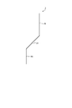
- FIG. 7 is a side view showing the crimp terminal 3 according to the first modified example of the first embodiment.
- the shape of the supported portion 31 may be an inclined shape extending obliquely from the insertion portion 30 toward the connection portion 32 .
- the support surface 21 of the terminal block 2 and the tip end surfaces of the pressing portions 40d and 41d of the cover 4 are also formed in an inclined shape along the inclination of the supported portion 31.
- FIG. 7 is a side view showing the crimp terminal 3 according to the first modified example of the first embodiment.
- the shape of the supported portion 31 may be an inclined shape extending obliquely from the insertion portion 30 toward the connection portion 32 .
- the support surface 21 of the terminal block 2 and the tip end surfaces of the pressing portions 40d and 41d of the cover 4 are also formed in an inclined shape along the inclination of the supported portion 31.
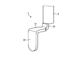
- FIG. 8 is a side view showing the crimp terminal 3 according to the second modified example of the first embodiment.
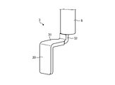
- FIG. 9 is a side view showing a crimp terminal 3 according to a third modified example of the first embodiment.
- the tip of the insertion portion 30 may be formed in an arc shape that protrudes toward the terminal block 2, or as shown in FIG. 9, the tip of the insertion portion 30 may be flat. may be formed.
- FIG. 10 is a perspective view showing an assembled state of the terminal block device 1A according to the second embodiment.
- FIG. 11 is an exploded perspective view showing the terminal block device 1A according to the second embodiment.
- FIG. 12 is an exploded perspective view showing the terminal block device 1A according to the second embodiment, and is a view of the terminal block device 1A viewed from an angle different from that of FIG.
- the present embodiment differs from the first embodiment described above in that the first cover 40 and the second cover 41 are connected to each other so as to be rotatable in the vertical direction.
- symbol is attached
- a shaft hole 40h penetrating in the Y-axis direction is formed at one end of the first cover 40 in the X-axis direction.
- 40 h of axial holes are formed in the edge part located in the X-axis direction of the 1st arm part 40b on the opposite side to the 1st boss part 40a.
- a substantially rectangular wall-shaped first contact portion 40i is formed at the other end portion of the first cover 40 in the X-axis direction. The first contact portion 40i protrudes toward the second cover 41 from the first boss portion 40a.
- one end of the second cover 41 in the X-axis direction is provided with a columnar rotating shaft 41f extending in the Y-axis direction.
- the rotating shaft 41f protrudes from the second boss portion 41a toward the first cover 40.
- the rotary shaft 41f is inserted through the shaft hole 40h.
- One ends of the first cover 40 and the second cover 41 in the X-axis direction are rotatably connected to each other via a rotating shaft 41f in a state in which the terminal block 2 is not covered.
- the first cover 40 is vertically rotatable about the rotation shaft 41f.
- the second cover 41 is vertically rotatable around the rotation shaft 41f. As shown in FIG.
- a second contact portion 41g that can come into contact with the first contact portion 40i is formed at the other end portion of the second cover 41 in the X-axis direction.
- the second contact portion 41g extends toward the terminal block 2 from the surface of the second arm portion 41b facing the terminal block 2, and then extends L in the direction away from the second arm portion 41b along the X-axis direction. It extends like a letter.
- the first contact portion 40i contacts the second contact portion 41g from the side opposite to the terminal block 2 in the Z-axis direction.
- one ends of the first cover 40 and the second cover 41 in the X-axis direction are vertically rotated through a rotating shaft 41f extending in the Y-axis direction.
- the first cover 40 can be rotated to cover the terminal block 2 . Therefore, it becomes easy to attach the first cover 40 along the electric wire 7 . Moreover, since one hand is free, attachment of the first cover 40 to the terminal block 2 is facilitated.
- the first contact portion 40i of the first cover 40 is connected to the second contact portion 40i of the second cover 41 from the opposite side of the terminal block 2 in the Z-axis direction. It contacts the contact portion 41g.
- the terminal block 2 is covered with the first cover 40, and the first cover 40 is fixed to the terminal block 2 by the fixing member 5.
- the first cover 40 and the second cover 41 can be fastened to the terminal block 2 together.
- FIG. 13 is a perspective view showing an assembled state of the terminal block device 1B according to the third embodiment.
- FIG. 14 is an exploded perspective view showing the terminal block device 1B according to the third embodiment, showing a state in which the cover 4 is closed.
- FIG. 15 is an exploded perspective view showing the terminal block device 1B according to the third embodiment, showing a state in which the cover 4 is opened.
- the present embodiment differs from the first embodiment described above in that the first cover 40 and the second cover 41 are connected to each other so as to be rotatable in the horizontal direction.
- symbol is attached
- two first mounting portions 40j are formed at one end of the first cover 40 in the X-axis direction.
- the two first mounting portions 40j are spaced apart from each other in the Z-axis direction.
- the first attachment portion 40j is formed at the end portion of the first arm portion 40b located on the opposite side of the first boss portion 40a in the X-axis direction.
- the first attachment portion 40j is formed in a rectangular plate shape.
- a shaft hole 40k penetrating in the Z-axis direction is formed in the first attachment portion 40j.
- the other end of the first cover 40 in the X-axis direction is formed with a rectangular plate-shaped insertion portion 40m.
- the insertion portion 40m protrudes toward the second cover 41 from the first boss portion 40a.
- a rectangular plate-shaped second mounting portion 41h is formed at one end of the second cover 41 in the X-axis direction.
- the second attachment portion 41h protrudes from the second boss portion 41a toward the first cover 40.
- the second mounting portion 41h is sandwiched between the two first mounting portions 40j in the Z-axis direction.
- a shaft hole (not shown) penetrating in the Z-axis direction is formed in the second mounting portion 41h.
- a concave portion 41i into which the insertion portion 40m is inserted is formed at the other end portion of the second cover 41 in the X-axis direction.
- the recess 41 i opens toward the X-axis direction and the first cover 40 .
- a cylindrical rotating shaft 43 extending in the Z-axis direction is inserted through the shaft hole 40k of the first mounting portion 40j and the shaft hole of the second mounting portion 41h.
- One ends of the first cover 40 and the second cover 41 in the X-axis direction are rotatably connected to each other via a rotating shaft 43 in a state in which the terminal block 2 is not covered.
- the first cover 40 is laterally rotatable around a rotation axis 43 .
- the second cover 41 is laterally rotatable around a rotating shaft 43 .
- one ends of the first cover 40 and the second cover 41 in the X-axis direction are laterally rotatable via a rotating shaft 43 extending in the Z-axis direction. connected to
- the electric wire 7 can be sandwiched. That is, the cover 4 functions as a cable holder that holds a plurality of wires 7 and slides along the wires 7 . Therefore, it becomes easy to attach the cover 4 along the electric wire 7 .
- the cover 4 can be fixed to the terminal block 2 in a state in which a plurality of electric wires 7 are inserted and held in the passage holes 42, the attachment of the cover 4 is facilitated.
- FIG. 16 is a diagram showing a state where the cover 4 of the terminal block device 1C according to the fourth embodiment is opened.
- FIG. 17 is a view showing a state in which the cover 4 of the terminal block device 1C according to the fourth embodiment is opened, and is a view of the terminal block device 1C from an angle different from that in FIG.
- FIG. 18 is a partially enlarged perspective view showing the first rotating shaft 40n and the first bearing portion 27 in the fourth embodiment.
- FIG. 19 is a perspective view showing the second cover 41 according to Embodiment 4.
- the present embodiment differs from the first embodiment described above in that the first cover 40 and the second cover 41 are rotatably connected to the terminal block 2 .
- symbol is attached
- one first fixing hole 23 and one second bearing 28 are formed at one end of the terminal block 2 in the X-axis direction.
- the second bearing portion 28 has a spherical recess.
- one second fixing hole 24 and one first bearing 27 are formed at the other end of the terminal block 2 in the X-axis direction.
- the first bearing portion 27 is generally formed in a C shape penetrating in the Y-axis direction.
- the positions of the first fixing hole 23 and the first bearing portion 27 match in the Y-axis direction.
- a first row of insertion holes 20 is arranged between the first fixing hole 23 and the first bearing portion 27 .
- the positions of the second fixing hole 24 and the second bearing portion 28 match in the Y-axis direction.
- a second row of insertion holes 20 is arranged between the second fixing hole 24 and the second bearing portion 28 .
- a first rotating shaft 40n extending in the Y-axis direction is provided at one end of the first cover 40 in the X-axis direction.
- the first rotating shaft 40n is formed at the end of the first arm portion 40b located on the opposite side of the first boss portion 40a in the X-axis direction.
- the first rotating shaft 40n is formed in a shape in which two cylinders with different diameters are connected.
- the large-diameter portion of the first rotating shaft 40n is in contact with the stepped surface formed on the inner peripheral surface of the first bearing portion 27 in the Y-axis direction, and the first rotating shaft 40n contacts the first bearing portion. 27 in the Y-axis direction.
- the first rotating shaft 40n is rotatably supported by the first bearing portion 27. As shown in FIG. One end of the first cover 40 in the X-axis direction is rotatably connected to the terminal block 2 via the first rotating shaft 40n and the first bearing portion 27 .
- the first cover 40 is vertically rotatable about a first rotating shaft 40n extending in the Y-axis direction.
- a second rotating shaft 41j projecting toward the terminal block 2 is provided at the other end of the second cover 41 in the X-axis direction.
- the second rotating shaft 41j is formed at the end of the second arm portion 41b located on the opposite side of the second boss portion 41a in the X-axis direction.
- the second rotating shaft 41j has a cylindrical proximal end and a spherical distal end.
- the tip of the second rotating shaft 41j is rotatably supported by the second bearing 28.
- the other end of the second cover 41 in the X-axis direction is rotatably connected to the terminal block 2 via a second rotating shaft 41j and a second bearing 28.
- the second cover 41 is rotatable vertically and horizontally around a second rotating shaft 41j. Since the second rotating shaft 41j is fitted in the second bearing portion 28, the structure is such that the second cover 41 and the terminal block 2 do not come off.
- the first cover 40 is rotatably connected to the terminal block 2 via the first rotating shaft 40n and the first bearing portion 27.
- the second cover 41 is rotatably connected to the terminal block 2 via a second rotating shaft 41 j and a second bearing portion 28 .
- Such a structure in which the first cover 40 and the second cover 41 are directly connected to the terminal block 2 facilitates the storage and transportation of the terminal block 2, the first cover 40 and the second cover 41. .
- FIG. 20 is an exploded perspective view of the terminal block device 1D according to the fifth embodiment, showing a state where the insertion portion 30 of the crimp terminal 3 is not inserted into the insertion hole 20.
- FIG. FIG. 21 is an exploded perspective view showing the terminal block device 1D according to the fifth embodiment, showing a state where the insertion portion 30 of the crimp terminal 3 is inserted into the insertion hole 20.
- FIG. FIG. 22 is a perspective view showing the cover 4 according to Embodiment 5.
- This embodiment differs from the first embodiment in that the crimp terminals 3 are oriented differently between the first and second rows and that one cover 4 is used.
- symbol is attached
- one end of the terminal block 2 is provided with a partition wall 29a that separates the insertion holes 20 and the shielding walls 22 in the first row from the insertion holes 20 and the shielding walls 22 in the second row.
- the partition wall 29a extends in the X-axis direction.
- the first row of insertion holes 20 and the second row of insertion holes 20 are arranged at the same height position in the Z-axis direction.
- One fixing hole 29b is formed at one end and the other end of the terminal block 2 in the X-axis direction.
- the two fixing holes 29b are arranged to be shifted in the Y-axis direction.
- the crimp terminals 3 in the first row and the crimp terminals 3 in the second row are arranged with the insertion portion 30 facing the partition wall 29a.
- the crimp terminals 3 in the first row and the crimp terminals 3 in the second row are arranged with the insertion portions 30 facing each other.
- the shape of the cover 4 is generally a rectangular parallelepiped that is longer in the X-axis direction than in the Y-axis direction in this embodiment.
- An insertion hole 44 is formed in the cover 4 at a position overlapping the fixing hole 29b in the Z-axis direction.
- the pressing portions 45 of the cover 4 are arranged in multiple rows in the Y-axis direction.
- the number of rows of the holding portion 45 is two in this embodiment.
- the pressing portions 45 in each row are arranged at the same intervals as the supported portions 31 and are spaced apart from each other in the X-axis direction.
- the crimp terminals 3 in the first row and the crimp terminals 3 in the second row are arranged with the insertion portions 30 facing each other, thereby forming the crimp terminals in the first row. 3 and the supported portion 31 of the crimp terminal 3 in the second row. Therefore, one cover 4 can press the supported portions 31 of the crimp terminals 3 in each row toward the terminal block 2 . Accordingly, by fixing the cover 4 to the terminal block 2 , the crimp terminals 3 in each row can be collectively fixed to the terminal block 2 , thereby facilitating the wiring work of the wires 7 . Further, by removing the cover 4 from the terminal block 2, the fixed state between the crimp terminals 3 in each row and the terminal block 2 can be released collectively, so maintenance work of the wires 7 can be facilitated.
Landscapes
- Connections Arranged To Contact A Plurality Of Conductors (AREA)
Abstract
端子台装置(1)は、複数の挿入孔(20)と、挿入孔(20)の縁に隣接する支持面(21)とが形成された端子台(2)と、挿入孔(20)に挿入される挿入部(30)と、挿入部(30)が挿入孔(20)に挿入された状態で挿入孔(20)の外部に配置されて支持面(21)に接触する被支持部(31)とを有する複数の圧着端子(3)と、被支持部(31)の、支持面(21)と反対側を向く面に接触して、端子台(2)に固定されるカバー(4)と、を備える。
Description
本開示は、端子台を備える端子台装置に関する。
従来、電線の接続、分岐、中継などのために使用される端子台装置が知られている。例えば、特許文献1には、端子台と、カバーとを備える端子台装置が開示されている。
特許文献1に開示された端子台の内部には、端子を収容する端子収容室が形成されている。端子には、電線が接続されている。端子台の外周壁には、端子収容室と端子台の外部とを連通する係止孔が形成されている。カバーには、係止孔に挿入可能な端子押え板が形成されている。特許文献1に開示された端子台装置では、端子収容室に端子を挿入した後、係止孔に端子押え板を挿入して端子を押すことにより、端子が正規の位置まで移動して固定される。
しかし、特許文献1に開示された技術では、端子台全体を端子台の内部に入れて、端子台の内部で端子とカバーの端子押え板とを接触させるため、端子の位置を目視で確認しながら端子にカバーの端子押え板を接触させることができないという問題がある。
本開示は、上記に鑑みてなされたものであって、端子の位置を目視で確認しながら端子にカバーを接触させることができる端子台装置を得ることを目的とする。
上述した課題を解決し、目的を達成するために、本開示にかかる端子台装置は、複数の挿入孔と、挿入孔の縁に隣接する支持面とが形成された端子台と、挿入孔に挿入される挿入部と、挿入部が挿入孔に挿入された状態で挿入孔の外部に配置されて支持面に接触する被支持部とを有する複数の圧着端子と、被支持部の、支持面と反対側を向く面に接触して、端子台に固定されるカバーと、を備える。
本開示にかかる端子台装置では、端子の位置を目視で確認しながら端子にカバーを接触させることができるという効果を奏する。
以下に、実施の形態にかかる端子台装置を図面に基づいて詳細に説明する。
実施の形態1.
図1は、実施の形態1にかかる端子台装置1の組付状態を示した斜視図である。図2は、実施の形態1にかかる端子台装置1を示した分解斜視図である。図3は、実施の形態1にかかる端子台装置1を示した分解斜視図であって、図2とは異なる角度から端子台装置1を見た図である。端子台装置1の形状は、特に制限されないが、本実施の形態では、図1に示すように概ね直方体である。図2および図3に示すように、端子台装置1は、端子台2と、複数の圧着端子3と、複数のカバー4と、複数の固定部材5とを備える。以下の説明において、端子台装置1の長手方向をX軸方向とし、端子台装置1の短手方向をY軸方向とし、端子台装置1の高さ方向をZ軸方向とする。第1の方向であるX軸方向と、第2の方向であるY軸方向と、Z軸方向とは、互いに直交する。
図1は、実施の形態1にかかる端子台装置1の組付状態を示した斜視図である。図2は、実施の形態1にかかる端子台装置1を示した分解斜視図である。図3は、実施の形態1にかかる端子台装置1を示した分解斜視図であって、図2とは異なる角度から端子台装置1を見た図である。端子台装置1の形状は、特に制限されないが、本実施の形態では、図1に示すように概ね直方体である。図2および図3に示すように、端子台装置1は、端子台2と、複数の圧着端子3と、複数のカバー4と、複数の固定部材5とを備える。以下の説明において、端子台装置1の長手方向をX軸方向とし、端子台装置1の短手方向をY軸方向とし、端子台装置1の高さ方向をZ軸方向とする。第1の方向であるX軸方向と、第2の方向であるY軸方向と、Z軸方向とは、互いに直交する。
端子台2は、X軸方向の長さがY軸方向の長さよりも長い概ね直方体状に形成されている。図4は、実施の形態1における端子台2を示した部分拡大斜視図である。図4に示すように、端子台2のうちZ軸方向の一端部には、複数の挿入孔20と複数の支持面21と複数の遮蔽壁22とが形成されている。挿入孔20は、Y軸方向に複数列配置されている。挿入孔20の列数は、本実施の形態では2列である。各列の挿入孔20は、X軸方向に互いに間隔を空けて配置されている。支持面21は、挿入孔20の縁に隣接する。支持面21は、X軸方向かつY軸方向に延びる平坦面である。支持面21と挿入孔20の開口とは、Y軸方向に並んで設けられている。支持面21は、1つの挿入孔20ごとに1つ設けられている。隣り合う挿入孔20および隣り合う支持面21の間には、矩形状の遮蔽壁22が設けられている。遮蔽壁22は、隣り合う圧着端子3の電気的絶縁距離を保つ役割を果たすとともに、後記する挿入部30を挿入孔20に挿入する際に圧着端子3をガイドする役割を果たす。圧着端子3の後記する被支持部31は、隣り合う2つの遮蔽壁22の間に嵌め込まれている。なお、遮蔽壁22を省略してもよい。このようにすると、各列において複数の挿入孔20の縁に隣接する1つの支持面21が形成される。
図3に示すように、端子台2のうちX軸方向の一端部には、第1の固定孔23と第2の支持壁26とが1つずつ形成されている。端子台2のうちX軸方向の他端部には、第2の固定孔24と第1の支持壁25とが1つずつ形成されている。第1の支持壁25および第2の支持壁26は、Z軸方向に沿って端子台2の一端部から離れる方向に延びている。第1の支持壁25には、X軸方向に貫通する矩形状の第1の差込孔25aが形成されている。第2の支持壁26には、X軸方向に貫通する矩形状の第2の差込孔26aが形成されている。第1の固定孔23と第1の差込孔25aとは、Y軸方向における位置が一致する。第1の固定孔23と第1の差込孔25aとの間には、一方の列の挿入孔20が配置されている。以下、この挿入孔20が並ぶ列を1列目と称する。第2の固定孔24と第2の差込孔26aとは、Y軸方向における位置が一致する。第2の固定孔24と第2の差込孔26aとの間には、他方の列の挿入孔20が配置されている。以下、この挿入孔20が並ぶ列を2列目と称する。
図4に示すように、圧着端子3は、接触子6と電線7とを電気的に接続する金属製の部材である。図5は、実施の形態1における圧着端子3、電線7および絶縁管8を示した斜視図である。図5に示すように、圧着端子3は、Z軸方向に延びる挿入部30と、挿入部30のうちZ軸方向の一端部からY軸方向に延びる被支持部31と、被支持部31のうち挿入部30と逆側に位置する端部からZ軸方向に延びる接続部32とを有している。圧着端子3は、一枚の金属板に折曲加工を施すことで形成されている。圧着端子3の形状は、クランク状である。挿入部30は、挿入孔20に挿入される板状の部分である。挿入部30の先端は、先細りとなる三角形状に形成されている。被支持部31は、X軸方向かつY軸方向に延びる平板状の部分である。被支持部31は、挿入部30に連続して形成されている。接続部32は、電線7と接続される板状の部分である。接続部32は、被支持部31に連続して形成されている。接続部32と電線7との接続箇所は、円筒状の絶縁管8により覆われている。
図2に示すように、カバー4は、複数の圧着端子3の被支持部31と接触して、端子台2に固定される部材である。カバー4は、端子台2の一端部を覆う。カバー4は、Y軸方向に並んで2つ配置されている。以下の説明において、2つのカバー4を区別する場合には、一方のカバー4を第1のカバー40と称し、他方のカバー4を第2のカバー41と称する。
第1のカバー40は、1列目の圧着端子3の被支持部31のそれぞれと接触する。第1のカバー40は、第1のボス部40aと、第1のボス部40aからX軸方向に沿って直線状に延びる第1のアーム部40bとを有している。第1のボス部40aは、概ね四角柱状の部分である。第1のボス部40aには、Z軸方向に貫通する第1の挿通孔40cが形成されている。第1の挿通孔40cの形状は、円形である。
第1のアーム部40bは、概ね四角壁状の部分である。第1のアーム部40bのうち端子台2の方を向く面には、端子台2に向かって突出する複数の第1の押え部40dが形成されている。第1の押え部40dは、被支持部31を押圧する部分である。第1の押え部40dの先端面は、X軸方向かつY軸方向に延びる平坦面である。複数の第1の押え部40dは、被支持部31と同じ配置間隔で、X軸方向に互いに間隔を空けて配置されている。第1のアーム部40bのうちX軸方向において第1のボス部40aと逆側に位置する面には、矩形板状の第1の突起部40eが突出している。
第1のアーム部40bのうち第2のカバー41の方を向く面には、第2のカバー41と接触可能な2つの接触面40fと、2つの接触面40fの間に配置されて接触面40fが第2のカバー41と接触した状態において第2のカバー41から離隔する切欠部40gとが形成されている。図1に示されるように接触面40fが第2のカバー41と接触して切欠部40gが第2のカバー41から離隔した状態において、第1のカバー40と第2のカバー41との間のうち切欠部40gと一致する箇所には、電線7が通過可能な通過孔42が形成される。通過孔42の形状は、矩形である。電線7は、Y軸方向に2列配置されており、2列目の電線7が通過孔42を通過する。1列目の電線7は、第1のカバー40を挟んで通過孔42と反対側に配置されている。
図3に示すように、第2のカバー41は、2列目の圧着端子3の被支持部31のそれぞれと接触する。第2のカバー41は、第2のボス部41aと、第2のボス部41aからX軸方向に沿って直線状に延びる第2のアーム部41bとを有している。第2のボス部41aは、概ね四角柱状の部分である。第1のボス部40aと第2のボス部41aとは、X軸方向において互いに逆側に配置されている。第2のボス部41aには、Z軸方向に貫通する第2の挿通孔41cが形成されている。第2の挿通孔41cの形状は、円形である。
第2のアーム部41bは、概ね四角壁状の部分である。第2のアーム部41bのうち端子台2の方を向く面には、端子台2に向かって突出する複数の第2の押え部41dが形成されている。第2の押え部41dは、被支持部31を押圧する部分である。第2の押え部41dの先端面は、X軸方向かつY軸方向に延びる平坦面である。複数の第2の押え部41dは、被支持部31と同じ配置間隔で、X軸方向に互いに間隔を空けて配置されている。第2のアーム部41bのうちX軸方向において第2のボス部41aと逆側に位置する面には、矩形板状の第2の突起部41eが突出している。
図1に示される固定部材5は、カバー4を端子台2に移動不能に固定する部材である。固定部材5は、本実施の形態ではネジであるが、カバー4を端子台2に移動不能に固定できれば特に制限されない。固定部材5は、例えば、スプリングピンでもよい。図2に示すように、第1の挿通孔40cと第1の固定孔23とには、1本の固定部材5が挿入される。また、第2の挿通孔41cと第2の固定孔24とには、1本の固定部材5が挿入される。電線7の配線時には、圧着端子3を挿入孔20に1個ずつ挿入する。そして、第1のカバー40の第1の突起部40eを第1の差込孔25aに差し込むとともに、第1の挿通孔40cと第1の固定孔23とに固定部材5をねじ込むことにより、第1のカバー40が端子台2に固定される。一方、図3に示すように、第2のカバー41の第2の突起部41eを第2の差込孔26aに差し込むとともに、第2の挿通孔41cと第2の固定孔24とに固定部材5をねじ込むことにより、第2のカバー41が端子台2に固定される。すなわち、各カバー4のうちX軸方向の一端部は、端子台2に嵌め込まれており、各カバー4のうちX軸方向の他端部は、固定部材5により端子台2に固定されている。
図6は、図1に示されたVI-VI線に沿った断面図である。図6は、挿入部30が挿入孔20に挿入された状態、かつ、カバー4が端子台2に固定された状態を図示している。挿入孔20の内部には、圧着端子3の挿入部30と接触する接触子6が設けられている。被支持部31は、挿入部30が挿入孔20に挿入された状態で、挿入孔20の外部に配置されて支持面21に接触している。被支持部31は、支持面21に面接触している。被支持部31の少なくとも1部が支持面21に接触していればよい。被支持部31および接続部32は、挿入孔20の外部に露出している。
カバー4は、被支持部31の、支持面21と反対側を向く面に接触している。カバー4が端子台2に固定された状態で、各被支持部31は、端子台2の支持面21とカバー4との間に挟み込まれている。固定部材5を締め付けることにより、カバー4を端子台2に引き寄せる力が働くため、カバー4が各被支持部31に押し当てられて、各被支持部31が端子台2に向かって押圧される。なお、図6では、カバー4が1つの被支持部31に接触している状態のみを図示しているが、実際には複数の被支持部31に同時に接触する。カバー4の第1の押え部40dおよび第2の押え部41dは、挿入孔20を覆っている。これにより、ゴミ、埃などが挿入孔20の内部に入りにくい構造になっている。
次に、本実施の形態にかかる端子台装置1の効果について説明する。
本実施の形態では、図3に示すように、端子台装置1は、端子台2と、複数の圧着端子3と、カバー4とを備える。端子台2には、複数の挿入孔20と、挿入孔20の縁に隣接する支持面21とが形成されている。図6に示すように、各圧着端子3は、挿入孔20に挿入される挿入部30と、挿入部30が挿入孔20に挿入された状態で挿入孔20の外部に配置されて支持面21に接触する被支持部31とを有する。カバー4は、被支持部31の、支持面21と反対側を向く面に接触して端子台2に固定される。これらの構成により、端子台2の外部で圧着端子3の被支持部31とカバー4とを接触させて、端子台2にカバー4を固定することで、端子台2に圧着端子3を移動不能に固定できる。つまり、圧着端子3の位置を目視で確認しながら圧着端子3にカバー4を接触させることができる。また、端子台2にカバー4を固定することで、複数の圧着端子3を一括して端子台2に固定できるため、電線7の配線作業が容易になる。また、端子台2からカバー4を外すことで、複数の圧着端子3と端子台2との固定状態を一括して解除できるため、電線7のメンテナンス作業が容易になる。また、圧着端子3のうち挿入孔20の外部に露出する部分を掴んで、挿入孔20への圧着端子3の抜き差しを容易に行えるため、電線7の配線作業およびメンテナンス作業がより一層容易になる。
本実施の形態では、図1に示すように、端子台装置1は、カバー4を端子台2に移動不能に固定する固定部材5を備え、カバー4が端子台2に固定された状態で、各被支持部31は、端子台2の支持面21とカバー4との間に挟み込まれている。これにより、端子台2に対するカバー4の着脱が容易になるため、作業者の作業量を減らすことができる。また、固定部材5であるネジの締付力を利用して、カバー4を介して被支持部31を押圧するため、圧着端子3の接続強度、すなわち電線7の引っ張り力に抵抗する引っ張り強度を高めることができる。
本実施の形態では、図3に示すように、挿入孔20は、X軸方向に互いに間隔を空けて配置されている。カバー4のうちX軸方向の一端部は、端子台2の差込孔25a,26aに差し込まれており、カバー4のうちX軸方向の他端部は、固定部材5により端子台2に固定されている。これにより、固定部材5による固定箇所を減らせるため、端子台2に対するカバー4の着脱がより一層容易になる。そのため、作業者の作業量をより一層減らすことができる。特に、本実施の形態では、1本の固定部材5でカバー4を端子台2に固定するため、1本の固定部材5を外すだけで、端子台2からカバー4を外せることから、電線7のメンテナンス作業がより一層容易になる。
本実施の形態では、図3に示すように、圧着端子3を挿入孔20にZ軸方向から挿入することにより、電線7をZ軸方向に延ばせるため、挿入孔20をY軸方向に複数列配置した場合でも、電線7同士の干渉を回避することができる。
本実施の形態では、図1に示すように、第1のカバー40には、第2のカバー41と接触可能な接触面40fと、接触面40fが第2のカバー41と接触した状態において第2のカバー41から離隔する切欠部40gとが形成されている。第1のカバー40と第2のカバー41との間のうち切欠部40gに一致する箇所には、電線7が通過可能な通過孔42が形成される。これにより、電線7の潰れを抑制できるため、隣り合う圧着端子3の間隔を狭めることができる。
なお、挿入孔20の列数は、図示した2列に限定されることなく、1列または3列以上の複数列でもよい。本実施の形態では、カバー4が端子台2とは別体で形成されているため、端子台2に形成される挿入孔20の列数に応じてカバー4の数を適宜変更できる。すなわち、カバー4の数を増やすことで、挿入孔20の列数が3列以上でも、圧着端子3の抜け止めを行うことができる。そのため、挿入孔20の列数の制限がなく、より多くの極数に対応できる。
なお、圧着端子3の形状は、図示した例に限定されることなく、適宜変更してよい。図7は、実施の形態1の第1変形例にかかる圧着端子3を示した側面図である。図7に示すように、被支持部31の形状は、挿入部30から接続部32に向かって斜めに延びる傾斜状でもよい。被支持部31の形状を傾斜状にする場合には、端子台2の支持面21およびカバー4の押え部40d,41dの先端面も被支持部31の傾斜に沿う傾斜状に形成される。
図8は、実施の形態1の第2変形例にかかる圧着端子3を示した側面図である。図9は、実施の形態1の第3変形例にかかる圧着端子3を示した側面図である。図8に示すように、挿入部30の先端は、端子台2に向かって凸となる円弧状に形成されてもよいし、図9に示すように、挿入部30の先端は、平坦状に形成されてもよい。
実施の形態2.
次に、図10から図12を参照して、実施の形態2にかかる端子台装置1Aについて説明する。図10は、実施の形態2にかかる端子台装置1Aの組付状態を示した斜視図である。図11は、実施の形態2にかかる端子台装置1Aを示した分解斜視図である。図12は、実施の形態2にかかる端子台装置1Aを示した分解斜視図であって、図11とは異なる角度から端子台装置1Aを見た図である。本実施の形態では、第1のカバー40と第2のカバー41とが互いに縦方向に回転可能に連結されている点が前記した実施の形態1と相違する。なお、実施の形態2では、前記した実施の形態1と重複する部分については、同一符号を付して説明を省略する。
次に、図10から図12を参照して、実施の形態2にかかる端子台装置1Aについて説明する。図10は、実施の形態2にかかる端子台装置1Aの組付状態を示した斜視図である。図11は、実施の形態2にかかる端子台装置1Aを示した分解斜視図である。図12は、実施の形態2にかかる端子台装置1Aを示した分解斜視図であって、図11とは異なる角度から端子台装置1Aを見た図である。本実施の形態では、第1のカバー40と第2のカバー41とが互いに縦方向に回転可能に連結されている点が前記した実施の形態1と相違する。なお、実施の形態2では、前記した実施の形態1と重複する部分については、同一符号を付して説明を省略する。
図12に示すように、第1のカバー40のうちX軸方向の一端部には、Y軸方向に貫通する軸孔40hが形成されている。軸孔40hは、第1のアーム部40bのうちX軸方向において第1のボス部40aと反対側に位置する端部に形成されている。図10に示すように、第1のカバー40のうちX軸方向の他端部には、概ね四角壁状の第1の接触部40iが形成されている。第1の接触部40iは、第1のボス部40aから第2のカバー41に向かって突出している。
図11に示すように、第2のカバー41のうちX軸方向の一端部には、Y軸方向に延びる円柱状の回転軸41fが設けられている。回転軸41fは、第2のボス部41aから第1のカバー40に向かって突出している。図12に示すように、回転軸41fは、軸孔40hに挿通されている。第1のカバー40および第2のカバー41のX軸方向の一端部同士は、端子台2に被せられていない状態において、回転軸41fを介して互いに回転可能に連結されている。第1のカバー40は、回転軸41fを中心として縦方向に回転可能である。第2のカバー41は、回転軸41fを中心として縦方向に回転可能である。図11に示すように、第2のカバー41のうちX軸方向の他端部には、第1の接触部40iと接触可能な第2の接触部41gが形成されている。第2の接触部41gは、第2のアーム部41bのうち端子台2を向く面から端子台2に向かって延びた後、X軸方向に沿って第2のアーム部41bから離れる方向にL字状に延びている。第1の接触部40iは、Z軸方向において端子台2と反対側から第2の接触部41gに接触する。
本実施の形態では、図11および図12に示すように、第1のカバー40および第2のカバー41のX軸方向の一端部同士は、Y軸方向に延びる回転軸41fを介して縦方向に回転可能に連結されていることにより、第2のカバー41を端子台2に固定した後、第1のカバー40を回転させて端子台2を覆うことができる。そのため、電線7に沿って第1のカバー40を付けやすくなる。また、片方の手が空くため、端子台2への第1のカバー40の取り付けが容易となる。
本実施の形態では、図11および図12に示すように、第1のカバー40の第1の接触部40iは、Z軸方向において端子台2と反対側から第2のカバー41の第2の接触部41gに接触する。これにより、第2のカバー41を端子台2に先に被せた後に、第1のカバー40を端子台2に被せて、固定部材5により第1のカバー40を端子台2に固定すると、第1のカバー40および第2のカバー41を端子台2に共締めできる。
実施の形態3.
次に、図13から図15を参照して、実施の形態3にかかる端子台装置1Bについて説明する。図13は、実施の形態3にかかる端子台装置1Bの組付状態を示した斜視図である。図14は、実施の形態3にかかる端子台装置1Bを示した分解斜視図であって、カバー4を閉じた状態を示した図である。図15は、実施の形態3にかかる端子台装置1Bを示した分解斜視図であって、カバー4を開けた状態を示した図である。本実施の形態では、第1のカバー40と第2のカバー41とが互いに横方向に回転可能に連結されている点が前記した実施の形態1と相違する。なお、実施の形態3では、前記した実施の形態1と重複する部分については、同一符号を付して説明を省略する。
次に、図13から図15を参照して、実施の形態3にかかる端子台装置1Bについて説明する。図13は、実施の形態3にかかる端子台装置1Bの組付状態を示した斜視図である。図14は、実施の形態3にかかる端子台装置1Bを示した分解斜視図であって、カバー4を閉じた状態を示した図である。図15は、実施の形態3にかかる端子台装置1Bを示した分解斜視図であって、カバー4を開けた状態を示した図である。本実施の形態では、第1のカバー40と第2のカバー41とが互いに横方向に回転可能に連結されている点が前記した実施の形態1と相違する。なお、実施の形態3では、前記した実施の形態1と重複する部分については、同一符号を付して説明を省略する。
図14に示すように、第1のカバー40のうちX軸方向の一端部には、2つの第1の取付部40jが形成されている。2つの第1の取付部40jは、Z軸方向に互いに間隔を空けて配置されている。第1の取付部40jは、第1のアーム部40bのうちX軸方向において第1のボス部40aと反対側に位置する端部に形成されている。第1の取付部40jは、四角板状に形成されている。第1の取付部40jには、Z軸方向に貫通する軸孔40kが形成されている。図15に示すように、第1のカバー40のうちX軸方向の他端部には、四角板状の差込部40mが形成されている。差込部40mは、第1のボス部40aから第2のカバー41に向かって突出している。
第2のカバー41のうちX軸方向の一端部には、四角板状の第2の取付部41hが形成されている。第2の取付部41hは、第2のボス部41aから第1のカバー40に向かって突出している。第2の取付部41hは、Z軸方向において2つの第1の取付部40jの間に挟み込まれている。第2の取付部41hには、Z軸方向に貫通する図示しない軸孔が形成されている。第2のカバー41のうちX軸方向の他端部には、差込部40mが差し込まれる凹部41iが形成されている。凹部41iは、X軸方向および第1のカバー40に向けて開口している。
第1の取付部40jの軸孔40kと第2の取付部41hの軸孔とには、Z軸方向に延びる円柱状の回転軸43が挿通されている。第1のカバー40および第2のカバー41のX軸方向の一端部同士は、端子台2に被せられていない状態において、回転軸43を介して互いに回転可能に連結されている。第1のカバー40は、回転軸43を中心として横方向に回転可能である。第2のカバー41は、回転軸43を中心として横方向に回転可能である。
本実施の形態では、図15に示すように、第1のカバー40および第2のカバー41のX軸方向の一端部同士は、Z軸方向に延びる回転軸43を介して横方向に回転可能に連結されている。これにより、第2のカバー41に対して第1のカバー40を横方向に回転させて、第1のカバー40と第2のカバー41とを閉じることで電線7を挟むことができる。すなわち、カバー4は、複数本の電線7を保持し、電線7に沿ってスライド移動するケーブル保持具として機能する。そのため、電線7に沿ってカバー4を付けやすくなる。また、複数本の電線7を通過孔42に入れて保持した状態で、カバー4を端子台2に固定できるため、カバー4の取り付けが容易になる。
実施の形態4.
次に、図16から図19を参照して、実施の形態4にかかる端子台装置1Cについて説明する。図16は、実施の形態4にかかる端子台装置1Cのカバー4を開けた状態を示した図である。図17は、実施の形態4にかかる端子台装置1Cのカバー4を開けた状態を示した図であって、図16とは異なる角度から端子台装置1Cを見た図である。図18は、実施の形態4における第1の回転軸40nおよび第1の軸受部27を示した部分拡大斜視図である。図19は、実施の形態4における第2のカバー41を示した斜視図である。本実施の形態では、第1のカバー40および第2のカバー41が端子台2に対して回転可能に連結されている点が前記した実施の形態1と相違する。なお、実施の形態4では、前記した実施の形態1と重複する部分については、同一符号を付して説明を省略する。
次に、図16から図19を参照して、実施の形態4にかかる端子台装置1Cについて説明する。図16は、実施の形態4にかかる端子台装置1Cのカバー4を開けた状態を示した図である。図17は、実施の形態4にかかる端子台装置1Cのカバー4を開けた状態を示した図であって、図16とは異なる角度から端子台装置1Cを見た図である。図18は、実施の形態4における第1の回転軸40nおよび第1の軸受部27を示した部分拡大斜視図である。図19は、実施の形態4における第2のカバー41を示した斜視図である。本実施の形態では、第1のカバー40および第2のカバー41が端子台2に対して回転可能に連結されている点が前記した実施の形態1と相違する。なお、実施の形態4では、前記した実施の形態1と重複する部分については、同一符号を付して説明を省略する。
図16に示すように、端子台2のうちX軸方向の一端部には、第1の固定孔23と第2の軸受部28とが1つずつ形成されている。第2の軸受部28は、球状の凹みを有する。図17に示すように、端子台2のうちX軸方向の他端部には、第2の固定孔24と第1の軸受部27とが1つずつ形成されている。第1の軸受部27は、Y軸方向に貫通する概ねC字状に形成されている。図16および図17に示すように、第1の固定孔23と第1の軸受部27とは、Y軸方向における位置が一致する。第1の固定孔23と第1の軸受部27との間には、1列目の挿入孔20が配置されている。第2の固定孔24と第2の軸受部28とは、Y軸方向における位置が一致する。第2の固定孔24と第2の軸受部28との間には、2列目の挿入孔20が配置されている。
図17に示すように、第1のカバー40のうちX軸方向の一端部には、Y軸方向に延びる第1の回転軸40nが設けられている。第1の回転軸40nは、第1のアーム部40bのうちX軸方向において第1のボス部40aと反対側に位置する端部に形成されている。図18に示すように、第1の回転軸40nは、直径が異なる2つ円柱が連なった形状に形成されている。第1の回転軸40nの大径部は、第1の軸受部27の内周面に形成された段差面とY軸方向で接触しており、第1の回転軸40nが第1の軸受部27からY軸方向に抜けることを抑制する役割を果たす。第1の回転軸40nは、第1の軸受部27に回転可能に支持されている。第1のカバー40のX軸方向の一端部は、第1の回転軸40nおよび第1の軸受部27を介して、端子台2に回転可能に連結されている。第1のカバー40は、Y軸方向に延びる第1の回転軸40nを中心として縦方向に回転可能である。
図16に示すように、第2のカバー41のうちX軸方向の他端部には、端子台2に向かって突出する第2の回転軸41jが設けられている。第2の回転軸41jは、第2のアーム部41bのうちX軸方向において第2のボス部41aと反対側に位置する端部に形成されている。図19に示すように、第2の回転軸41jは、円柱状の基端部と球状の先端部とを有している。図16に示すように、第2の回転軸41jの先端部は、第2の軸受部28に回転可能に支持されている。第2のカバー41のX軸方向の他端部は、第2の回転軸41jおよび第2の軸受部28を介して、端子台2に回転可能に連結されている。第2のカバー41は、第2の回転軸41jを中心として縦方向および横方向に回転可能である。第2の回転軸41jが第2の軸受部28に嵌まることで、第2のカバー41と端子台2とが外れない構造になっている。
本実施の形態では、図17に示すように、第1のカバー40は、第1の回転軸40nおよび第1の軸受部27を介して、端子台2に回転可能に連結されており、図16に示すように、第2のカバー41は、第2の回転軸41jおよび第2の軸受部28を介して、端子台2に回転可能に連結されている。このように第1のカバー40および第2のカバー41を端子台2に直接連結する構造にすると、端子台2、第1のカバー40および第2のカバー41の保管、運搬などが容易になる。
実施の形態5.
次に、図20から図22を参照して、実施の形態5にかかる端子台装置1Dについて説明する。図20は、実施の形態5にかかる端子台装置1Dを示した分解斜視図であって、圧着端子3の挿入部30が挿入孔20に挿入されていない状態を示した図である。図21は、実施の形態5にかかる端子台装置1Dを示した分解斜視図であって、圧着端子3の挿入部30が挿入孔20に挿入された状態を示した図である。図22は、実施の形態5におけるカバー4を示した斜視図である。本実施の形態では、1列目と2列目とで圧着端子3の向きが異なる点と、1つのカバー4を用いた点が前記した実施の形態1と相違する。なお、実施の形態5では、前記した実施の形態1と重複する部分については、同一符号を付して説明を省略する。
次に、図20から図22を参照して、実施の形態5にかかる端子台装置1Dについて説明する。図20は、実施の形態5にかかる端子台装置1Dを示した分解斜視図であって、圧着端子3の挿入部30が挿入孔20に挿入されていない状態を示した図である。図21は、実施の形態5にかかる端子台装置1Dを示した分解斜視図であって、圧着端子3の挿入部30が挿入孔20に挿入された状態を示した図である。図22は、実施の形態5におけるカバー4を示した斜視図である。本実施の形態では、1列目と2列目とで圧着端子3の向きが異なる点と、1つのカバー4を用いた点が前記した実施の形態1と相違する。なお、実施の形態5では、前記した実施の形態1と重複する部分については、同一符号を付して説明を省略する。
図20に示すように、端子台2の一端部には、1列目の挿入孔20および遮蔽壁22と2列目の挿入孔20および遮蔽壁22とを隔てる隔壁29aが設けられている。隔壁29aは、X軸方向に延びている。1列目の挿入孔20と2列目の挿入孔20とは、Z軸方向において同じ高さ位置に配置されている。端子台2のうちX軸方向の一端部および他端部には、固定孔29bが1つずつ形成されている。2つの固定孔29bは、Y軸方向にずれて配置されている。
1列目の圧着端子3と2列目の圧着端子3とは、挿入部30を隔壁29aに向けて配置される。換言すると、1列目の圧着端子3と2列目の圧着端子3とは、挿入部30を互いに向かい合わせて配置される。
カバー4は、本実施の形態では1つである。カバー4の形状は、本実施の形態ではY軸方向よりもX軸方向に長い概ね直方体である。カバー4には、Z軸方向で固定孔29bと重なる位置に挿通孔44が形成されている。図22に示すように、カバー4の押え部45は、Y軸方向に複数列配置されている。押え部45の列数は、本実施の形態では2列である。各列の押え部45は、被支持部31と同じ配置間隔で、X軸方向に互いに間隔を空けて配置されている。
本実施の形態では、図20に示すように、1列目の圧着端子3と2列目の圧着端子3とが挿入部30を互いに向かい合わせて配置されることにより、1列目の圧着端子3の被支持部31と2列目の圧着端子3の被支持部31との間に電線7が存在しない。そのため、1つのカバー4で、各列の圧着端子3のそれぞれの被支持部31を端子台2に向かって押圧できる。これにより、端子台2にカバー4を固定することで、各列の圧着端子3を一括して端子台2に固定できるため、電線7の配線作業が容易になる。また、端子台2からカバー4を外すことで、各列の圧着端子3と端子台2との固定状態を一括して解除できるため、電線7のメンテナンス作業が容易になる。
以上の実施の形態に示した構成は、一例を示すものであり、別の公知の技術と組み合わせることも可能であるし、実施の形態同士を組み合わせることも可能であるし、要旨を逸脱しない範囲で、構成の一部を省略、変更することも可能である。
1,1A,1B,1C,1D 端子台装置、2 端子台、3 圧着端子、4 カバー、5 固定部材、6 接触子、7 電線、8 絶縁管、20 挿入孔、21 支持面、22 遮蔽壁、23 第1の固定孔、24 第2の固定孔、25 第1の支持壁、25a 第1の差込孔、26 第2の支持壁、26a 第2の差込孔、27 第1の軸受部、28 第2の軸受部、29a 隔壁、29b 固定孔、30 挿入部、31 被支持部、32 接続部、40 第1のカバー、40a 第1のボス部、40b 第1のアーム部、40c 第1の挿通孔、40d 第1の押え部、40e 第1の突起部、40f 接触面、40g 切欠部、40h,40k 軸孔、40i 第1の接触部、40j 第1の取付部、40m 差込部、40n 第1の回転軸、41 第2のカバー、41a 第2のボス部、41b 第2のアーム部、41c 第2の挿通孔、41d 第2の押え部、41e 第2の突起部、41f,43 回転軸、41g 第2の接触部、41h 第2の取付部、41i 凹部、41j 第2の回転軸、42 通過孔、44 挿通孔、45 押え部。
Claims (6)
- 複数の挿入孔と、前記挿入孔の縁に隣接する支持面とが形成された端子台と、
前記挿入孔に挿入される挿入部と、前記挿入部が前記挿入孔に挿入された状態で前記挿入孔の外部に配置されて前記支持面に接触する被支持部とを有する複数の圧着端子と、
前記被支持部の、前記支持面と反対側を向く面に接触して、前記端子台に固定されるカバーと、を備えることを特徴とする端子台装置。 - 前記カバーを前記端子台に移動不能に固定する固定部材を備え、
前記カバーが前記端子台に固定された状態で、各前記被支持部は、前記端子台の前記支持面と前記カバーとの間に挟み込まれていることを特徴とする請求項1に記載の端子台装置。 - 前記挿入孔は、第1の方向に互いに間隔を空けて配置され、
前記カバーのうち前記第1の方向の一端部は、前記端子台に形成された差込孔に差し込まれており、前記カバーのうち前記第1の方向の他端部は、前記固定部材により前記端子台に固定されていることを特徴とする請求項2に記載の端子台装置。 - 前記挿入孔は、前記第1の方向と直交する第2の方向に複数列配置されていることを特徴とする請求項3に記載の端子台装置。
- 前記カバーは、前記第2の方向に並んで2つ配置されており、
2つの前記カバーの前記第1の方向の一端部同士は、回転軸を介して互いに回転可能に連結されていることを特徴とする請求項4に記載の端子台装置。 - 2つの前記カバーのうち一方には、他方の前記カバーと接触可能な接触面と、前記接触面が他方の前記カバーと接触した状態において他方の前記カバーから離隔する切欠部とが形成されており、
2つの前記カバーの間のうち前記切欠部に一致する箇所には、前記圧着端子に接続される電線が通過可能な通過孔が形成されていることを特徴とする請求項5に記載の端子台装置。
Priority Applications (3)
| Application Number | Priority Date | Filing Date | Title |
|---|---|---|---|
| PCT/JP2021/022566 WO2022264229A1 (ja) | 2021-06-14 | 2021-06-14 | 端子台装置 |
| JP2021569219A JP7042993B1 (ja) | 2021-06-14 | 2021-06-14 | 端子台装置 |
| CN202180062543.4A CN116325368B (zh) | 2021-06-14 | 2021-06-14 | 端子台装置 |
Applications Claiming Priority (1)
| Application Number | Priority Date | Filing Date | Title |
|---|---|---|---|
| PCT/JP2021/022566 WO2022264229A1 (ja) | 2021-06-14 | 2021-06-14 | 端子台装置 |
Publications (1)
| Publication Number | Publication Date |
|---|---|
| WO2022264229A1 true WO2022264229A1 (ja) | 2022-12-22 |
Family
ID=81214511
Family Applications (1)
| Application Number | Title | Priority Date | Filing Date |
|---|---|---|---|
| PCT/JP2021/022566 Ceased WO2022264229A1 (ja) | 2021-06-14 | 2021-06-14 | 端子台装置 |
Country Status (3)
| Country | Link |
|---|---|
| JP (1) | JP7042993B1 (ja) |
| CN (1) | CN116325368B (ja) |
| WO (1) | WO2022264229A1 (ja) |
Citations (4)
| Publication number | Priority date | Publication date | Assignee | Title |
|---|---|---|---|---|
| JP2002246107A (ja) * | 2001-02-16 | 2002-08-30 | Sumitomo Wiring Syst Ltd | コネクタ |
| CN106256049A (zh) * | 2013-12-18 | 2016-12-21 | Afci连接器新加坡私人有限公司 | 电缆连接器及其连接器组件 |
| JP2017027747A (ja) * | 2015-07-22 | 2017-02-02 | 矢崎総業株式会社 | コネクタ |
| JP2019030143A (ja) * | 2017-07-31 | 2019-02-21 | 日本電産テクノモータ株式会社 | コネクタ及びコネクタを備えたモータ |
Family Cites Families (2)
| Publication number | Priority date | Publication date | Assignee | Title |
|---|---|---|---|---|
| JP3546426B2 (ja) * | 1999-11-05 | 2004-07-28 | 理化工業株式会社 | 計器類の端子カバー構造および計器類の端子カバー |
| JP5707854B2 (ja) * | 2010-01-15 | 2015-04-30 | オムロン株式会社 | 端子台 |
-
2021
- 2021-06-14 CN CN202180062543.4A patent/CN116325368B/zh active Active
- 2021-06-14 JP JP2021569219A patent/JP7042993B1/ja active Active
- 2021-06-14 WO PCT/JP2021/022566 patent/WO2022264229A1/ja not_active Ceased
Patent Citations (4)
| Publication number | Priority date | Publication date | Assignee | Title |
|---|---|---|---|---|
| JP2002246107A (ja) * | 2001-02-16 | 2002-08-30 | Sumitomo Wiring Syst Ltd | コネクタ |
| CN106256049A (zh) * | 2013-12-18 | 2016-12-21 | Afci连接器新加坡私人有限公司 | 电缆连接器及其连接器组件 |
| JP2017027747A (ja) * | 2015-07-22 | 2017-02-02 | 矢崎総業株式会社 | コネクタ |
| JP2019030143A (ja) * | 2017-07-31 | 2019-02-21 | 日本電産テクノモータ株式会社 | コネクタ及びコネクタを備えたモータ |
Also Published As
| Publication number | Publication date |
|---|---|
| CN116325368B (zh) | 2024-03-26 |
| JPWO2022264229A1 (ja) | 2022-12-22 |
| CN116325368A (zh) | 2023-06-23 |
| JP7042993B1 (ja) | 2022-03-28 |
Similar Documents
| Publication | Publication Date | Title |
|---|---|---|
| US7329143B2 (en) | Electrical terminal with a spring force clamping terminal for two conductors | |
| US6231392B1 (en) | Cable interconnection | |
| JP5588773B2 (ja) | ワイヤカバー、電気コネクタ | |
| KR102233059B1 (ko) | 커넥터 | |
| JP5722565B2 (ja) | ワイヤカバー、電線の配線方法、電気コネクタ | |
| CN111448715B (zh) | 端子保持体、线束、固定结构 | |
| US20190252831A1 (en) | Connector assembly with grounging clamp system | |
| KR20180017204A (ko) | 전기 플러그 커넥터 | |
| CN1682410A (zh) | 设有侧向锁定装置的插塞式连接器 | |
| US5846101A (en) | Connection block for connecting electrical conductors to electrical equipment | |
| US20060199423A1 (en) | Press-contact connector | |
| JPH09293570A (ja) | 情報ネットワーク用ソケット | |
| WO2022264229A1 (ja) | 端子台装置 | |
| JP5359321B2 (ja) | アース接続用配線材、これに用いられるジョイントコネクタ、及びアース接続用配線材が組み込まれたワイヤハーネス | |
| CA2828624C (en) | System of plug connectors fixed on mounting rails | |
| US7223119B2 (en) | Cable connector assembly and system | |
| CN1518164B (zh) | 将模块电气装置单元与电源梳电连接的电连接装置 | |
| JP2009224155A (ja) | 照明器具 | |
| JP2018049702A (ja) | コネクタ、コネクタカバー、及び、ワイヤハーネス | |
| JP6248912B2 (ja) | スプライス部の絶縁構造、ハーネス配置プレートおよび配線ユニット | |
| JP5325698B2 (ja) | 電線接続ユニット | |
| KR100542063B1 (ko) | 전기 커넥터 | |
| JPH08115757A (ja) | ケーブル・電線接続用端子台 | |
| JP2600600Y2 (ja) | Fpc/ffc用コネクタ装置 | |
| JP5159909B2 (ja) | プラグ付属部品 |
Legal Events
| Date | Code | Title | Description |
|---|---|---|---|
| ENP | Entry into the national phase |
Ref document number: 2021569219 Country of ref document: JP Kind code of ref document: A |
|
| 121 | Ep: the epo has been informed by wipo that ep was designated in this application |
Ref document number: 21945909 Country of ref document: EP Kind code of ref document: A1 |
|
| NENP | Non-entry into the national phase |
Ref country code: DE |
|
| 122 | Ep: pct application non-entry in european phase |
Ref document number: 21945909 Country of ref document: EP Kind code of ref document: A1 |