WO2022260081A1 - 端子付キャパシタ及びキャパシタ内蔵コネクタ - Google Patents
端子付キャパシタ及びキャパシタ内蔵コネクタ Download PDFInfo
- Publication number
- WO2022260081A1 WO2022260081A1 PCT/JP2022/023121 JP2022023121W WO2022260081A1 WO 2022260081 A1 WO2022260081 A1 WO 2022260081A1 JP 2022023121 W JP2022023121 W JP 2022023121W WO 2022260081 A1 WO2022260081 A1 WO 2022260081A1
- Authority
- WO
- WIPO (PCT)
- Prior art keywords
- terminal
- partial joint
- joint portion
- capacitor
- partial
- Prior art date
- Legal status (The legal status is an assumption and is not a legal conclusion. Google has not performed a legal analysis and makes no representation as to the accuracy of the status listed.)
- Ceased
Links
Images




Classifications
-
- H—ELECTRICITY
- H01—ELECTRIC ELEMENTS
- H01G—CAPACITORS; CAPACITORS, RECTIFIERS, DETECTORS, SWITCHING DEVICES, LIGHT-SENSITIVE OR TEMPERATURE-SENSITIVE DEVICES OF THE ELECTROLYTIC TYPE
- H01G4/00—Fixed capacitors; Processes of their manufacture
- H01G4/32—Wound capacitors
-
- H—ELECTRICITY
- H01—ELECTRIC ELEMENTS
- H01G—CAPACITORS; CAPACITORS, RECTIFIERS, DETECTORS, SWITCHING DEVICES, LIGHT-SENSITIVE OR TEMPERATURE-SENSITIVE DEVICES OF THE ELECTROLYTIC TYPE
- H01G4/00—Fixed capacitors; Processes of their manufacture
- H01G4/002—Details
- H01G4/228—Terminals
-
- H—ELECTRICITY
- H01—ELECTRIC ELEMENTS
- H01G—CAPACITORS; CAPACITORS, RECTIFIERS, DETECTORS, SWITCHING DEVICES, LIGHT-SENSITIVE OR TEMPERATURE-SENSITIVE DEVICES OF THE ELECTROLYTIC TYPE
- H01G4/00—Fixed capacitors; Processes of their manufacture
- H01G4/002—Details
- H01G4/228—Terminals
- H01G4/232—Terminals electrically connecting two or more layers of a stacked or rolled capacitor
-
- H—ELECTRICITY
- H01—ELECTRIC ELEMENTS
- H01G—CAPACITORS; CAPACITORS, RECTIFIERS, DETECTORS, SWITCHING DEVICES, LIGHT-SENSITIVE OR TEMPERATURE-SENSITIVE DEVICES OF THE ELECTROLYTIC TYPE
- H01G9/00—Electrolytic capacitors, rectifiers, detectors, switching devices, light-sensitive or temperature-sensitive devices; Processes of their manufacture
- H01G9/004—Details
- H01G9/008—Terminals
-
- H—ELECTRICITY
- H01—ELECTRIC ELEMENTS
- H01R—ELECTRICALLY-CONDUCTIVE CONNECTIONS; STRUCTURAL ASSOCIATIONS OF A PLURALITY OF MUTUALLY-INSULATED ELECTRICAL CONNECTING ELEMENTS; COUPLING DEVICES; CURRENT COLLECTORS
- H01R13/00—Details of coupling devices of the kinds covered by groups H01R12/70 or H01R24/00 - H01R33/00
- H01R13/66—Structural association with built-in electrical component
- H01R13/6608—Structural association with built-in electrical component with built-in single component
- H01R13/6625—Structural association with built-in electrical component with built-in single component with capacitive component
-
- H—ELECTRICITY
- H01—ELECTRIC ELEMENTS
- H01R—ELECTRICALLY-CONDUCTIVE CONNECTIONS; STRUCTURAL ASSOCIATIONS OF A PLURALITY OF MUTUALLY-INSULATED ELECTRICAL CONNECTING ELEMENTS; COUPLING DEVICES; CURRENT COLLECTORS
- H01R24/00—Two-part coupling devices, or either of their cooperating parts, characterised by their overall structure
- H01R24/28—Coupling parts carrying pins, blades or analogous contacts and secured only to wire or cable
Definitions
- the present disclosure relates to a capacitor with terminals and a connector with a built-in capacitor.
- Patent Document 1 discloses forming a convex portion on a bus bar and soldering this convex portion to a metallikon electrode of a film capacitor.
- an object of the present disclosure is to improve the bonding strength between the external electrodes and the terminals of the capacitor element.
- a terminal-equipped capacitor of the present disclosure includes a capacitor element including a pair of electrodes, a pair of external electrodes connected to each of the pair of electrodes, and a terminal including a joint portion joined to one of the pair of external electrodes. and wherein the joint portion includes a first partial joint portion and a second partial joint portion, and the extending direction of both side edges of the first partial joint portion is aligned with both side edges of the second partial joint portion. and both side edges of the first partial joint portion and both side edges of the second partial joint portion are joined to the one external electrode.
- FIG. 1 is a plan view showing a connector with a built-in capacitor.
- FIG. 2 is a front view showing a connector with a built-in capacitor.
- FIG. 3 is a cross-sectional view taken along line III--III in FIG.
- FIG. 4 is a perspective view showing a capacitor with terminals.
- FIG. 5 is a schematic cross-sectional view showing the internal structure of the capacitor element.
- FIG. 6 is a diagram showing a connection portion between a terminal and a capacitor element.
- FIG. 7 is a plan view showing another terminal.
- FIG. 8 is a diagram showing a connecting portion between another terminal and a capacitor element.
- the terminal-equipped capacitor of the present disclosure is as follows.
- a capacitor element including a pair of electrodes and a pair of external electrodes connected to each of the pair of electrodes; and a terminal including a joint portion joined to one of the pair of external electrodes,
- the joint portion includes a first partial joint portion and a second partial joint portion, and the extending direction of both side edges of the first partial joint portion is the extending direction of both side edges of the second partial joint portion and both side edges of the first partial joint portion and both side edges of the second partial joint portion are joined to the one external electrode.
- the joints are joined to the external electrodes in at least four locations. Also, the joint includes portions that extend in at least two different directions. Therefore, the bonding strength between the external electrode and the terminal of the capacitor element is improved.
- the joint portion includes a third partial joint portion, and the extending direction of both side edges of the third partial joint portion is the second portion.
- the second partial joint connects the first partial joint and the third partial joint, and the third partial joint intersects with the extending direction of both side edges of the joint. may be joined to the one external electrode. Thereby, the bonding strength between the external electrode and the terminal of the capacitor element is further improved.
- the first partial joint, the second partial joint, and the third partial joint each have a shape extending linearly, and the first partial joint and the third partial joint extend parallel to each other, and the second partial joint is perpendicular to the first partial joint and the third partial joint;
- the tip of the partial joint and the tip of the third partial joint may be connected.
- the strength of the joint as a whole can be increased while the first partial joint, the second partial joint, and the third partial joint are thinned.
- the first partial joint portion, the second partial joint portion, and the third partial joint portion can be easily heated. are easily joined to the external electrodes.
- the third partial junction extends along the edge of the external electrode, and the first partial junction is closer than the third partial junction. It may be located near the center of the external electrode.
- the terminal includes a terminal body extending outward from the joint portion, and the terminal body is on the joint portion side.
- a through portion penetrating through both surfaces may be formed at the end of the . Since the end of the terminal body on the joint side has a penetrating portion penetrating through both sides, heat from the joint is less likely to escape to the terminal body, and the joint can be easily joined to the external electrode.
- the capacitor built-in connector of the present disclosure is as follows.
- a capacitor built-in connector includes a housing that accommodates a capacitor element, and a sealing portion that seals the capacitor element within the housing. A portion of the terminal exposed from the housing can be used to connect wiring from the outside to the capacitor element via the terminal. Since the bonding strength of the terminal to the capacitor element is improved, it is possible to prevent the terminal from coming off from the capacitor element when the terminal-equipped capacitor is incorporated into the housing.
- FIG. 1 is a plan view showing a connector 10 with a built-in capacitor.
- FIG. 2 is a front view showing the connector 10 with a built-in capacitor.
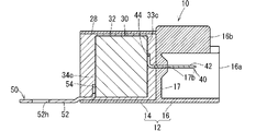
- FIG. 3 is a cross-sectional view taken along line III--III in FIG.
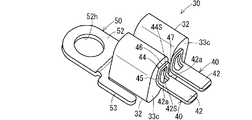
- FIG. 4 is a perspective view showing the capacitor 30 with terminals.
- the capacitor built-in connector 10 includes a terminal-equipped capacitor 30 , a housing 12 and a sealing portion 28 .
- the terminal-equipped capacitor 30 has a configuration in which terminals 40 and 50 are joined to a capacitor element 32 .
- Terminals 40 and 50 may be referred to as busbars.
- the terminal capacitor 30 has two capacitor elements 32 .
- a terminal 40 is joined to one end of each of the two capacitor elements 32 .
- a common terminal 50 is joined to the other ends of the two capacitor elements.
- Two terminals 40 extend in parallel from one ends of the two capacitor elements 32 arranged in parallel.
- One terminal 50 extends in the opposite direction from the two terminals 40 from the other ends of the two capacitor elements 32 .
- the terminal-equipped capacitor 30 may include one capacitor element 32 .
- the terminal-equipped capacitor 30 has one terminal 40 joined to the one capacitor element 32 .
- the terminal 50 is joined to only the one capacitor element 32 concerned.
- the housing 12 is a member that accommodates the capacitor element 32 .
- the housing 12 is made of an insulating material such as resin.
- the housing 12 is, for example, a member integrally molded with a resin.
- Housing 12 includes an element housing portion 14 and a connector housing portion 16 .
- the element housing portion 14 is formed in the shape of a rectangular parallelepiped box having an opening.
- a capacitor element 32 here, two capacitor elements 32 arranged in parallel are accommodated in the space within the element accommodating portion 14 .
- the space inside the element accommodating portion 14 is formed to have a size that allows the capacitor element 32 to be accommodated without protruding to the outside.
- the connector housing portion 16 is formed in a cylindrical shape that is open in one direction.
- the connector housing portion 16 is configured to form one cylinder in which an outwardly protruding projection forming portion 16b is connected to the center of a portion corresponding to the long side of a main body portion 16a having a rectangular tubular shape.
- the projecting portion 16 b is formed to project along the longitudinal direction of the connector housing portion 16 .
- a slit 16h extending along the longitudinal direction of the projecting portion 16b is formed on the outward surface of the projecting portion 16b except for the portion on the opening side of the connector housing portion 16.
- a receiving piece 16br extending along the width direction of the connector housing portion 16 is provided at a portion on the opening side of the connector housing portion 16 with respect to the slit 16h.
- a mating connector (not shown) connected to the main connector housing portion 16 is inserted into the connector housing portion 16 .
- the locking portion formed on the mating connector can be inserted into the slit 16h and locked to the receiving piece 16br.
- a partition portion 17 is formed between the element housing portion 14 and the connector housing portion 16 .
- the partition portion 17 is a portion that forms the bottom of the internal space of the element housing portion 14 and the bottom of the connector housing portion 16 .
- 17 h of terminal insertion holes in which the terminal 40 is inserted are formed in the partition part 17. As shown in FIG. Here, two terminal insertion holes 17h are formed corresponding to the two terminals 40. As shown in FIG. It is preferable that the terminal insertion hole 17h has a size to which the terminal 40 is press-fitted.
- the terminal 40 With the capacitor element 32 accommodated in the element accommodating portion 14, the terminal 40 is inserted into the terminal insertion hole 17h. A tip portion of the terminal 40 opposite to the end connected to the capacitor element 32 is exposed to the outside inside the connector housing portion 16 .
- the terminals 40 are inserted and connected to the mating terminals in the mating connector.
- a tip portion of the terminal 50 is fixed to a fixing target portion.
- the tip of the terminal 50 is formed with a hole 52h. By inserting a screw through the hole 52h and screwing it into the screw hole on the fixing target portion side, the tip portion of the terminal 50 is fixed to the fixing target portion.
- the fixing target portion is, for example, a grounding target portion such as a metal body of the vehicle.
- the sealing portion 28 seals the capacitor element 32 inside the element housing portion 14 .
- the sealing portion 28 is formed, for example, by filling the element accommodating portion 14 with a resin in a fluid state while the capacitor element 32 is accommodated in the element accommodating portion 14 and then curing the resin.
- Epoxy resin is generally used as the resin to be filled, but it may be a resin melted by heat, a moisture-curing liquid resin, or a light-curing liquid resin.
- the connector 10 with a built-in capacitor is installed in the vehicle as a noise countermeasure component for, for example, a defogger, a high-mounted stop lamp, etc., interposed between the power supply circuit and the ground circuit.
- the capacitor built-in connector 10 may be incorporated in electrical equipment other than vehicles, industrial equipment, and the like.
- the terminal 50 is fixed in a state of being grounded to the grounding target portion, and the mating connector on the power supply side is connected to the connector housing portion 16 .
- the terminal-equipped capacitor 30 will be described more specifically. As described above, the terminal-equipped capacitor 30 includes the capacitor element 32 and the terminals 40 and 50 .
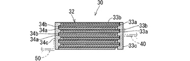
- FIG. 5 is a schematic cross-sectional view showing the internal structure of the capacitor element 32.
- Capacitor element 32 includes a pair of electrodes 33a, 34a and external electrodes 33c, 34c connected to the pair of electrodes 33a, 34a, respectively.
- a dielectric is provided between the pair of electrodes 33a and 34a.
- the electrode 33a is formed by vapor-depositing aluminum or the like on one side of the dielectric film 33b.
- An electrode 34a is formed by vapor-depositing aluminum or the like on one side of the dielectric film 34b.
- the electrode 33a, the film 33b, the electrode 34a, and the film 34b are stacked in this order, and the stack is wound. As a result, the electrodes 33a and 34a are rolled up while being separated by the films 33b and 34b, and charges can be stored between the electrodes 33a and 34a.
- the film 33b on which the electrode 33a is formed and the film 34b on which the electrode 34a is formed are wound while being shifted in the direction along the winding axis. Therefore, the electrode 33a and the film 33b protrude from the electrode 34a and the film 34b on one side in the axial direction of the wound body, and the electrode 34a and the film 34b protrude from the electrodes 34a and 34b on the other side in the axial direction of the wound body. It protrudes from 33a and film 33b and is exposed.
- An external electrode 33c is formed on one side in the axial direction of the wound body.
- the external electrode 33c is an electrode that is exposed on one axial end surface of the wound body while being connected to the electrode 33a.
- An external electrode 34c is formed on the other axial side of the wound body.
- the external electrode 34c is an electrode that is exposed on the other axial end surface of the wound body while being connected to the electrode 34a.
- the external electrodes 33c, 34c are formed by, for example, melting a thermal spraying material such as zinc-tin alloy, tin, aluminum, etc., and spraying it onto one side or the other side of the winding body in the axial direction.
- the sprayed thermal spray material is joined to the electrode 33a on one side in the axial direction of the wound body to form the external electrode 33c.
- the sprayed thermal spray material is joined to the electrode 34a on the other side in the axial direction of the wound body to form the external electrode 34c.
- the external electrodes 33c and 34c are exposed at one end side or the other end side of the capacitor element 32 in the axial direction.
- the external electrodes 33c, 34c present outward surfaces perpendicular to the axial direction of the wound body.
- Such external electrodes 33c and 34c may be called metallikon electrodes.
- a terminal 40 is connected to each of the external electrodes 33 c of the two capacitor elements 32 .
- a common terminal 50 is connected to the external electrodes 34 c of the two capacitor elements 32 .
- the terminal-equipped capacitor 30 has both the terminals 40 and 50 .
- an electric wire may be used instead of one of the terminals 40 and 50 and the electric wire may be connected to the external electrode 33 c or 34 c of the capacitor element 32 .
- FIG. 6 is a diagram showing a connection portion between the terminal 40 and the capacitor element 32. As shown in FIG.
- the terminal 40 is joined to the external electrode 33c, which is one of the pair of external electrodes 33c and 34c.
- the terminal 40 is formed, for example, by pressing a plate made of copper, copper alloy, or the like.
- a plated layer of tin, nickel, or the like may be formed on the surface of the terminal 40 .
- the terminal 40 includes a terminal body 42 and a joint portion 44 .
- the terminal main body 42 is a part used for connection with a connection target.
- the terminal main body 42 is formed in a straight plate shape, and is inserted and connected to the mating terminal.
- the joint portion 44 is a portion that is joined to the external electrode 33c.
- the joint portion 44 is connected to the terminal main body 42 in a bent state.
- the joint portion 44 and the terminal main body 42 are connected at an angle of 90 degrees.
- the joint portion 44 and the terminal body 42 may be connected at an angle other than 90 degrees, or may be connected straight.
- the joint portion 44 includes a first partial joint portion 45 and a second partial joint portion 46 .
- the extending direction of both side edges of the first partial joint portion 45 intersects the extending direction of both side edges of the second partial joint portion 46 .
- Both side edges of the first partial joint portion 45 and both side edges of the second partial joint portion 46 are joined to the external electrode 33c.
- the first partial joint portion 45 is formed in an elongated plate shape extending from one end of the edge of the terminal main body 42 on the base end side.
- the first partial joint portion 45 is bent perpendicularly to the terminal body 42 and extends to one main surface side of the terminal body 42 .
- the second partial joint portion 46 extends from the tip of the first partial joint portion 45 in a direction crossing the first partial joint portion 45 .
- the second partial joint portion 46 bends from the tip portion of the first partial joint portion 45 and extends perpendicularly to the first partial joint portion 45 .
- the second partial joint portion 46 may face the center side in the width direction of the terminal body 42 as shown in FIG. 4 and the like.
- the second partial joint portion 46 may face outward in the width direction of the terminal body 42 .
- the extension direction of the second partial joint portion 46 is parallel to the extension direction of the proximal edge of the terminal body 42 .
- the length of the second partial joint portion 46 is about the width dimension of the terminal body 42 .
- the first partial joint portion 45 is formed in the shape of a straight plate with a continuous uniform width portion, and the second partial joint portion 46 is also formed in a straight plate shape with a continuous uniform width portion. Therefore, both side edges of the first partial joint portion 45 extend in parallel, and both side edges of the second partial joint portion 46 also extend in parallel. Also, the extending direction of both side edges of the first partial joint portion 45 crosses (here, perpendicular to) the extending direction of both side edges of the second partial joint portion 46 . That is, the first partial joint portion 45 and the second partial joint portion 46 are continuous in an L shape.
- the terminal 40 also includes a third partial joint portion 47 .
- the extending direction of both side edges of the third partial joint portion 47 intersects with the extending direction of both side edges of the second partial joint portion 46 .
- a second partial joint 46 connects the first partial joint 45 and the third partial joint 47 .
- the third partial joint portion 47 is formed in an elongated plate shape extending from the other end portion of the base end side edge of the terminal body 42 .
- the first partial joint portion 45 and the third partial joint portion 47 are spaced apart from the base end edge of the terminal body 42 .
- the third partial joint portion 47 is formed in an elongated plate shape.
- the third partial joint portion 47 is bent perpendicularly to the terminal body 42 and extends to one main surface side of the terminal body 42 . Therefore, the first joint portion 45 and the third joint portion 47 extend parallel to each other with a space therebetween.
- the third partial joint portion 47 is formed in the shape of a straight plate with equal width portions continuing. Therefore, both side edges of the third partial joint portion 47 extend in parallel. The extending direction of both side edges of the third partial joint portion 47 crosses (here, perpendicular to) the extending direction of both side edges of the second partial joint portion 46 .
- the second partial joint 46 connects the tip of the first partial joint 45 and the tip of the third partial joint 47 .
- the second partial joint 46 is perpendicular to both the first partial joint 45 and the third partial joint 47 . For this reason, the first partial joint portion 45, the second partial joint portion 46, and the third partial joint portion 47 are vertically connected in a U-shape.
- the first partial joint portion 45, the second partial joint portion 46, and the third partial joint portion 47 may be formed with the same width, or may be formed with different widths.
- the first partial joint portion 45, the second partial joint portion 46, and the third partial joint portion 47 may be formed with the same width of 1 mm.
- the first partial joint portion 45 may be formed with a width of 1.5 mm
- the second partial joint portion 46 may be formed with a width of 0.9 mm.
- the third partial joint portion 47 may be omitted.
- an opening here, a rectangular opening 44S is formed.
- a penetrating portion 42S penetrating on both sides is formed at the end portion of the terminal body 42 on the joint portion 44 side, that is, the portion of the terminal body 42 closer to the joint portion 44 than the center in the longitudinal direction thereof.
- the opening 44S is continuous with the penetrating portion 42S of the terminal main body 42.
- the first partial joint portion 45 and the third partial joint portion 47 are connected to both ends of the proximal edge of the terminal body 42, and an opening 44S is formed therebetween.
- the opening 44S extends toward the base end side of the terminal body 42 and forms a through portion 42S.
- a pair of narrow connecting portions 42a are provided on both sides of the through portion 42S of the terminal body 42. As shown in FIG.
- the narrow connecting portion 42 a has the same width as the first partial joint portion 45 or the third partial joint portion 47 and is narrower than the terminal main body 42 .
- the through portion 42S does not need to be a space continuous with the opening 44S, and may be formed as a through hole separate from the opening 44S.
- first partial joint portion 45, the second partial joint portion 46, and the third partial joint portion 47 are formed in a straight plate shape. Therefore, between the first partial joint portion 45, the second partial joint portion 46, and the third partial joint portion 47, an opening having a shape other than the rectangular opening 44S, for example, a circular opening is formed. may For this reason, it is not essential that all the edges of the first partial joint portion 45, the second partial joint portion 46, and the third partial joint portion 47 are straight. may be When a part of the edges of the first partial joint portion 45, the second partial joint portion 46, and the third partial joint portion 47 is curved, whether or not it intersects another edge depends on the edge that draws the curve. Any tangent line may be used as a reference for determination. For example, if any tangent line of a curvilinear edge intersects another straight edge, the two edges are said to intersect.
- the joint portion 44 is joined to the outward surface of the external electrode 33c as shown in FIG. That is, both side edges of the first partial joint portion 45 are joined by the weld portion 45p. Also, both side edges of the second partial joint portion 46 are joined by a weld portion 46p. Preferably, at least one edge of the third partial joint portion 47 is joined by a weld portion 47p.
- the positions of the welded portions 45p, 46p, and 47p in FIG. 6 are examples.
- the welded portion 45p may be formed in a larger or smaller area with respect to the side edge of the first partial joint 45 .
- the welded portion 45p at the side edge of the first partial joint portion 45 and the welded portion 46p at the side edge of the second partial joint portion 46 may be integrally connected.
- the welded portions 45p, 46p, and 47p are portions where at least one of the external electrode 33c and the joint portion 44 is melted and then solidified, thereby joining the joint portion 44 and the external electrode 33c.
- the joint portion 44 and the external electrode 33c are electrically connected to each other, and both are mechanically fixed so as to maintain a certain positional relationship. state.
- connection between the joint portion 44 and the external electrode 33c is performed, for example, as follows. That is, the surface of the joint portion 44 opposite to the terminal main body 42 is brought into contact with the outward surface of the external electrode 33c.
- the outer edge of the third partial joint portion 47 is extended along the edge of the external electrode 33c. may be placed.
- the first partial joint portion 45 is more likely to be arranged closer to the center of the external electrode 33c than the third partial joint portion 47, with the third partial joint portion 47 arranged along the edge of the external electrode 33c as a reference.
- the outer edge of the third partial joint portion 47 and the edge of the external electrode 33c can be easily aligned by visual confirmation. Further, by bringing the outer edge of the third partial joint portion 47 and the edge of the external electrode 33c into contact with a positioning jig, both edges can be easily aligned.
- a pair of tip electrodes 60 for resistance welding are brought into contact with the joint 44 while the joint 44 is in contact with the external electrode 33c.
- a pair of tip electrodes 60 is indicated by two-dot chain lines.
- the pair of tip electrodes 60 are electrodes for applying a voltage for resistance welding to the object to be welded.
- the tip surfaces of the pair of tip electrodes 60 are formed to have a diameter of 3 mm, for example, and the distance between the pair of tip electrodes 60 is set to 0.5 mm, for example.
- a pair of tip electrodes 60 are pressed against either the first partial joint portion 45 or the second partial joint portion 46 . At this time, if the width of the first partial joint portion 45 and the second partial joint portion 46 is larger than the interval between the pair of tip electrodes 60, the pair of chip electrodes 60 are separated from the first partial joint portion 45 or the second partial joint portion 46. simultaneously.
- the contact portion between the joint 44 and the chip electrode 60 When the pair of chip electrodes 60 are pressed against either the first partial joint 45 or the second partial joint 46, the contact portion between the joint 44 and the chip electrode 60 generates Joule heat due to contact resistance. This heat melts the external electrode 33c, and the both side edges of the first partial joint portion 45 and the both side edges of the second partial joint portion 46 are welded to the external electrode 33c by resistance welding. Any one edge of the third partial joint portion 47, particularly the edge on the first partial joint portion 45 side, may be welded to the external electrode 33c in the same manner as described above. An edge of the third partial joint portion 47 opposite to the first partial joint portion 45 may be joined to the external electrode 33c.
- the terminals 40 are welded as described above.
- the external electrode 33c and the joint portion 44 may be joined by solder.
- the terminal 50 is joined to the external electrode 34c.
- 7 is a plan view showing the terminal 50
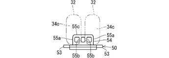
- FIG. 8 is a diagram showing the connecting portion between the terminal 50 and the capacitor element 32.
- the capacitor element 32 is indicated by a two-dot chain line.
- the terminal 50 is formed, for example, by pressing a plate made of copper, copper alloy, or the like.
- a plated layer of tin, nickel, or the like may be formed on the surface of the terminal 50 .
- the terminal 50 includes a terminal body 52 and a joint portion 54 .
- the terminal main body 52 is a part used for connection with a connection target.
- the terminal main body 52 is formed in the shape of a straight plate, and a hole 52h is formed in the tip portion thereof. By inserting a screw through the hole 52h and screwing the terminal main body 52 to the fixing target location, the terminal body 52 is fixed to the fixing target location and electrically connected.
- the joint portion 54 is a portion that is joined to the external electrode 34c. In this embodiment, the joint portion 54 and the terminal main body 52 are connected at an angle of 90 degrees. The joint portion 54 and the terminal body 52 may be connected at an angle other than 90 degrees, or may be connected straight.
- a pair of extension pieces 53 are formed at the base end portion of the terminal main body 52 and at positions outside the joint portion 54 .
- the pair of extension pieces 53 are positioned below the bottom surfaces of the two capacitor elements 32 and outside the two capacitor elements 32 .
- the pair of extension pieces 53 come into contact with the inner surface of the element housing portion 14 within the element housing portion 14 and can play a role of keeping the position of the terminal-equipped capacitor 30 constant.
- the extension piece 53 may be omitted.
- the joint portion 54 includes a pair of side pieces 55a, 55a and intermediate pieces 55b, 55b between the pair of side pieces 55a, 55a. Also, the tip of the pair of side pieces 55a, 55a and the tip of the pair of intermediate pieces 55b, 55b are connected by a connecting piece 55c. Openings are formed between one side piece 55a and one intermediate piece 55b, between a pair of intermediate pieces 55b, and between the other side piece 55a and the other intermediate piece 55b.
- one side piece 55 a is a portion corresponding to the first partial joint portion 45
- a portion between one side piece 55 a and one intermediate piece 55 b of the connecting piece 55 c is the second partial joint portion 46 .
- the joint portion 54 is joined to the external electrode 34c of one capacitor element 32 .
- one intermediate piece 55b may be joined to the external electrode 34c as a portion similar to the third partial joint portion 47 described above.
- the other side piece 55a is the portion corresponding to the first partial joint portion 45, and the portion between the other side piece 55a and the other intermediate piece 55b of the connecting piece 55c is the second partial joint portion 46.
- the joint portion 54 is joined to the external electrode 34c of the other capacitor element 32 .
- the other intermediate piece 55b may be joined to the external electrode 34c as a portion similar to the third partial joint portion 47 described above.
- the external electrodes are connected to the external electrodes at at least four joint portions 44, that is, both side edges of the first partial joint portion 45 and both side edges of the second partial joint portion 46, respectively. 33c. Therefore, the bonding area increases. Also, the joints extend in at least two different directions. Therefore, the welded portions 45p along both side edges of the first partial joint portion 45 and the welded portions 46p along both side edges of the second partial joint portion 46 can reinforce each other.
- first partial joint 45 For example, if only both side edges of the first partial joint 45 are joined to the external electrode 33c, and the first partial joint 45 is tilted about the axial direction of the first partial joint 45, welding The portion 45p may easily break. However, if both side edges of the second partial joint portion 46 are joined to the external electrode 33c, the force that causes the first partial joint portion 45 to be tilted around its axis can be received by the weld portion 46p. In this way, the force that tends to separate the first partial joint portion 45 from the external electrode 33c is effectively received by the welded portions 45p and 46p extending in a plurality of directions. Thereby, the bonding strength between the external electrode 33c of the capacitor element 32 and the terminal 40 is improved, and the reliability of the connection is improved.
- the extending direction of both side edges of the first partial joint portion 45 is orthogonal to the extending direction of both side edges of the second partial joint portion 46, the forces in various directions applied to the terminal 40 are applied to the first It can be effectively received by the welded portion 45p, which is a joint portion on both side edges of the partial joint portion 45, and the welded portion 46p, which is a joint portion on both side edges of the second partial joint portion 46.
- the bonding strength between the external electrode 33c of the capacitor element 32 and the terminal 40 is further improved.
- the joint strength between the external electrode 33c of the capacitor element 32 and the terminal 40 is further improved.
- first partial joint portion 45, the second partial joint portion 46, and the third partial joint portion 47 are each formed in the shape of a straight plate, and are connected in a U-shape as a whole while being orthogonal to each other. Therefore, the strength of the joint portion 44 as a whole can be increased while the first partial joint portion 45, the second partial joint portion 46, and the third partial joint portion 47 are thinned. As a result, terminal 40 is firmly fixed to capacitor element 32 . Further, by thinning the first partial joint portion 45, the second partial joint portion 46, and the third partial joint portion 47, it becomes easier to heat them, and it becomes easier to join the joint portion 44 to the external electrode 33c. Further, even when the terminal 40 is subjected to processing such as plating, the joint portion 44 is less likely to be deformed.
- the second partial joint portion 46 intersects the first partial joint portion 45 .
- the joint portion 44 is only the first partial joint portion 45
- a first Precise work is required to precisely position the partial joints 45 .
- the second partial joint portion 46 intersects the first partial joint portion 45, even if both of the pair of tip electrodes 60 cannot be brought into contact with the first partial joint portion 45, at least one It is easy to bring the tip electrode 60 into contact with the second partial joint portion 46 . This makes it possible to easily perform resistance welding by bringing the pair of tip electrodes 60 into contact with either the first partial joint portion 45 or the second partial joint portion 46 .
- the pair of tip electrodes 60 are brought into contact with any one of the first partial joint 45, the second partial joint 46, and the third partial joint 47 to perform resistance welding. can be performed, and resistance welding can be performed more easily.
- the third partial joint portion 47 is along the edge of the external electrode 33c, and the first partial joint portion 45 is located closer to the center of the external electrode 33c than the third partial joint portion 47 is.
- the first partial joint portion 45 is easily joined to a position closer to the center of the external electrode 33c with reference to the position of the third partial joint portion 47 with respect to the edge of the external electrode 33c, and the joint portion 44 is stably connected to the outside. It is joined to the electrode 33c.
- the effect of improving the junction strength can be obtained in the same manner as described above.
- the terminal main body 42 is provided with the through portion 42S at the end portion of the terminal 40 on the joint portion 44 side, the heat of the joint portion 44 is less likely to escape to the terminal main body 42 side, and the joint portion 44 is connected to the external electrode 33c. Easier to connect.
- wiring from the outside can be connected to the capacitor element 32 using the portion (terminal body 42 ) of the terminal 40 exposed from the housing 12 . Since the bonding strength of the terminal body 42 to the capacitor element is improved, the terminal 40 is prevented from coming off from the capacitor element 32 when the terminal-equipped capacitor 30 is incorporated into the housing 12 . For example, when the terminal 40 is inserted into the terminal insertion hole 17h, especially when the terminal 40 is press-fitted into the terminal insertion hole 17h, even if an excessive force is applied to the base of the terminal 40, the terminal 40 may come off from the capacitor element 32. hard.
- capacitor built-in connector 12 housing 14 element accommodating portion 16 connector housing portion 16a main body portion 16b projection forming portion 16h slit 16br receiving piece 17 partition portion 17h terminal insertion hole 28 sealing portion 30 capacitor with terminal 32 capacitor elements 33a, 34a electrode 33b, 34b Films 33c, 34c External electrodes 40, 50 Terminals 42, 52 Terminal main body 42S Penetrating portion 42a Narrow connecting portions 44, 54 Joint portion 44S Opening 45 First partial joint portions 45p, 46p, 47p Welding portion 46 Second partial joint portion 47 Third partial joint portion 52h Hole 53 Extension piece 55a Side piece 55b Intermediate piece 55c Connection piece 60 Tip electrode
Landscapes
- Engineering & Computer Science (AREA)
- Power Engineering (AREA)
- Microelectronics & Electronic Packaging (AREA)
- Manufacturing & Machinery (AREA)
- Fixed Capacitors And Capacitor Manufacturing Machines (AREA)
- Details Of Connecting Devices For Male And Female Coupling (AREA)
Priority Applications (2)
| Application Number | Priority Date | Filing Date | Title |
|---|---|---|---|
| US18/562,400 US20240170217A1 (en) | 2021-06-11 | 2022-06-08 | Terminal-equipped capacitor and capacitor-integrated connector |
| CN202280037625.8A CN117378024A (zh) | 2021-06-11 | 2022-06-08 | 带端子的电容器和电容器内置连接器 |
Applications Claiming Priority (2)
| Application Number | Priority Date | Filing Date | Title |
|---|---|---|---|
| JP2021-098166 | 2021-06-11 | ||
| JP2021098166A JP7538780B2 (ja) | 2021-06-11 | 2021-06-11 | 端子付キャパシタ及びキャパシタ内蔵コネクタ |
Publications (1)
| Publication Number | Publication Date |
|---|---|
| WO2022260081A1 true WO2022260081A1 (ja) | 2022-12-15 |
Family
ID=84426063
Family Applications (1)
| Application Number | Title | Priority Date | Filing Date |
|---|---|---|---|
| PCT/JP2022/023121 Ceased WO2022260081A1 (ja) | 2021-06-11 | 2022-06-08 | 端子付キャパシタ及びキャパシタ内蔵コネクタ |
Country Status (4)
| Country | Link |
|---|---|
| US (1) | US20240170217A1 (https=) |
| JP (1) | JP7538780B2 (https=) |
| CN (1) | CN117378024A (https=) |
| WO (1) | WO2022260081A1 (https=) |
Citations (4)
| Publication number | Priority date | Publication date | Assignee | Title |
|---|---|---|---|---|
| JPS63184312A (ja) * | 1986-09-19 | 1988-07-29 | 日立エーアイシー株式会社 | チップ型コンデンサ |
| JPH03122524U (https=) * | 1990-03-27 | 1991-12-13 | ||
| JPH0645178A (ja) * | 1992-07-24 | 1994-02-18 | Nissei Denki Kk | 電子部品 |
| JPH09134847A (ja) * | 1995-11-08 | 1997-05-20 | Fujiken:Kk | コンデンサ |
Family Cites Families (1)
| Publication number | Priority date | Publication date | Assignee | Title |
|---|---|---|---|---|
| JP3122524U (ja) | 2006-04-04 | 2006-06-15 | 徐銘燦 | 自転車大ギア構造 |
-
2021
- 2021-06-11 JP JP2021098166A patent/JP7538780B2/ja active Active
-
2022
- 2022-06-08 WO PCT/JP2022/023121 patent/WO2022260081A1/ja not_active Ceased
- 2022-06-08 US US18/562,400 patent/US20240170217A1/en not_active Abandoned
- 2022-06-08 CN CN202280037625.8A patent/CN117378024A/zh active Pending
Patent Citations (4)
| Publication number | Priority date | Publication date | Assignee | Title |
|---|---|---|---|---|
| JPS63184312A (ja) * | 1986-09-19 | 1988-07-29 | 日立エーアイシー株式会社 | チップ型コンデンサ |
| JPH03122524U (https=) * | 1990-03-27 | 1991-12-13 | ||
| JPH0645178A (ja) * | 1992-07-24 | 1994-02-18 | Nissei Denki Kk | 電子部品 |
| JPH09134847A (ja) * | 1995-11-08 | 1997-05-20 | Fujiken:Kk | コンデンサ |
Also Published As
| Publication number | Publication date |
|---|---|
| CN117378024A (zh) | 2024-01-09 |
| JP2022189537A (ja) | 2022-12-22 |
| JP7538780B2 (ja) | 2024-08-22 |
| US20240170217A1 (en) | 2024-05-23 |
Similar Documents
| Publication | Publication Date | Title |
|---|---|---|
| EP0650226B1 (en) | A molded circuit component unit for connecting lead wires and a method of manufacturing same | |
| US20090122489A1 (en) | Electronic control device and method of manufacturing electronic control device | |
| JP2000333343A (ja) | バッテリ接続プレートとその製造方法 | |
| JP7681843B2 (ja) | コンデンサ | |
| CN108335821A (zh) | 线圈元件 | |
| JP7382721B2 (ja) | 平板状電線の接続構造及び該接続構造を備えるワイヤハーネス | |
| JP2018139484A (ja) | 電気接続装置、この装置および電子基板を備えるアセンブリ、および電子基板の電気接続方法 | |
| WO2019107128A1 (ja) | コンデンサ | |
| US9006879B2 (en) | Semicondutor device package placed within fitting portion of wiring member and attached to heat sink | |
| JP2004253167A (ja) | アース端子 | |
| WO2022260081A1 (ja) | 端子付キャパシタ及びキャパシタ内蔵コネクタ | |
| US11431142B2 (en) | Method of manufacturing electric wire with terminal and electric wire with terminal | |
| WO2025187610A1 (ja) | 端子台 | |
| US7663469B2 (en) | Thermistor device and method for manufacturing the same | |
| CN104022364B (zh) | 端子与汇流条的连接结构 | |
| JP7140797B2 (ja) | 端子接続構造 | |
| WO2023026846A1 (ja) | バスバーユニット、及び配線モジュール | |
| JP7645496B2 (ja) | コンデンサ | |
| JP7380483B2 (ja) | 車載用配線モジュール | |
| US20240234012A1 (en) | Electric arrangement with a choke coil | |
| US20240170797A1 (en) | Wiring module | |
| WO2023210371A1 (ja) | 配線モジュール | |
| JP4132990B2 (ja) | 電気的接合構造 | |
| JP2025110673A (ja) | コンデンサ | |
| WO2024157693A1 (ja) | コンデンサ |
Legal Events
| Date | Code | Title | Description |
|---|---|---|---|
| 121 | Ep: the epo has been informed by wipo that ep was designated in this application |
Ref document number: 22820260 Country of ref document: EP Kind code of ref document: A1 |
|
| WWE | Wipo information: entry into national phase |
Ref document number: 18562400 Country of ref document: US |
|
| WWE | Wipo information: entry into national phase |
Ref document number: 202280037625.8 Country of ref document: CN |
|
| NENP | Non-entry into the national phase |
Ref country code: DE |
|
| 122 | Ep: pct application non-entry in european phase |
Ref document number: 22820260 Country of ref document: EP Kind code of ref document: A1 |