WO2022259428A1 - 光学系、撮像装置、及び投射装置 - Google Patents
光学系、撮像装置、及び投射装置 Download PDFInfo
- Publication number
- WO2022259428A1 WO2022259428A1 PCT/JP2021/021942 JP2021021942W WO2022259428A1 WO 2022259428 A1 WO2022259428 A1 WO 2022259428A1 JP 2021021942 W JP2021021942 W JP 2021021942W WO 2022259428 A1 WO2022259428 A1 WO 2022259428A1
- Authority
- WO
- WIPO (PCT)
- Prior art keywords
- prism
- lens
- optical system
- flat plate
- plate portion
- Prior art date
- Legal status (The legal status is an assumption and is not a legal conclusion. Google has not performed a legal analysis and makes no representation as to the accuracy of the status listed.)
- Ceased
Links
Images






Classifications
-
- H—ELECTRICITY
- H04—ELECTRIC COMMUNICATION TECHNIQUE
- H04N—PICTORIAL COMMUNICATION, e.g. TELEVISION
- H04N23/00—Cameras or camera modules comprising electronic image sensors; Control thereof
- H04N23/50—Constructional details
- H04N23/55—Optical parts specially adapted for electronic image sensors; Mounting thereof
-
- G—PHYSICS
- G02—OPTICS
- G02B—OPTICAL ELEMENTS, SYSTEMS OR APPARATUS
- G02B26/00—Optical devices or arrangements for the control of light using movable or deformable optical elements
- G02B26/08—Optical devices or arrangements for the control of light using movable or deformable optical elements for controlling the direction of light
-
- G—PHYSICS
- G02—OPTICS
- G02B—OPTICAL ELEMENTS, SYSTEMS OR APPARATUS
- G02B26/00—Optical devices or arrangements for the control of light using movable or deformable optical elements
- G02B26/08—Optical devices or arrangements for the control of light using movable or deformable optical elements for controlling the direction of light
- G02B26/0875—Optical devices or arrangements for the control of light using movable or deformable optical elements for controlling the direction of light by means of one or more refracting elements
- G02B26/0883—Optical devices or arrangements for the control of light using movable or deformable optical elements for controlling the direction of light by means of one or more refracting elements the refracting element being a prism
-
- G—PHYSICS
- G02—OPTICS
- G02B—OPTICAL ELEMENTS, SYSTEMS OR APPARATUS
- G02B27/00—Optical systems or apparatus not provided for by any of the groups G02B1/00 - G02B26/00, G02B30/00
- G02B27/01—Head-up displays
- G02B27/017—Head mounted
- G02B27/0172—Head mounted characterised by optical features
Definitions
- the present invention relates to an optical system used for focusing, and an imaging device and a projection device using the optical system.
- Patent Document 1 discloses a method of focusing on an oblique plane with a depth difference. According to the technique disclosed in Japanese Patent Application Laid-Open No. 2002-200010, a reflecting mirror having a special aspect is arranged between the document surface (imaging surface) and the imaging device.
- Patent Document 2 discloses a method of focusing on an oblique plane with a depth difference. According to the technique disclosed in Patent Document 2, a reflector having a special aspect is arranged between a spatial light modulator such as a liquid crystal or a DMD (Digital Mirror Device) and a projection surface.
- a spatial light modulator such as a liquid crystal or a DMD (Digital Mirror Device)
- a reflecting mirror with a special aspect generally uses a free-form surface mirror, which requires a large manufacturing cost. Therefore, the optical system becomes expensive.
- the size of the reflecting mirror described above corresponds to the angle of view of imaging, so the size of the optical system is increased.
- the focal plane 9 perpendicularly crosses the optical axis 8 (broken line) is focused. That is, it is focused at a position different from the projected surface 7 .
- the optical system in one aspect is an imaging device that converts light into an electrical signal; a lens that refracts and focuses light; a prism disposed between the optical path of the imaging element and the lens; A virtual image of the light-receiving surface of the imaging device is formed in the prism, and a focal plane is positioned conjugate with the virtual image through the lens.
- the optical system in one aspect is a display element for displaying an image; a lens that refracts and focuses light; a prism disposed between the optical path of the display element and the lens; A virtual image of the surface of the display element is formed in the prism, and the projected surface is positioned conjugate with the virtual image through the lens.
- a projection device includes: a display element for displaying an image; a lens that refracts and focuses light; a prism disposed between the optical path of the display element and the lens; A virtual image of the surface of the display element is formed in the prism, and the projected surface is positioned conjugate with the virtual image through the lens.
- FIG. 1 is a diagram for explaining a conventional imaging device.
- FIG. 2 is a diagram for explaining a conventional projection device.
- FIG. 3 is a diagram for explaining an example of the optical system according to the first embodiment;
- FIG. 4 is a diagram for explaining an example of a prism according to Embodiment 1.
- FIG. 5 is a diagram for explaining a prism design method.
- FIG. 6 is a diagram showing the relationship between the position of the focal plane and the object distance.
- FIG. 7 is a diagram showing the relationship between the position of the image plane having an image forming relationship with the in-focus plane and the image distance.
- FIG. 8 is a diagram for explaining the prism design method of the first embodiment.
- FIG. 9 is a diagram for explaining an example of a system having the imaging device of Embodiment 1.
- FIG. 19 is a diagram for explaining an in-focus plane according to the third embodiment.
- FIG. 20 is a diagram for explaining an example of an optical system that the projection device has.
- FIG. 21 is a diagram for explaining another prism example of the fourth embodiment.
- FIG. 22 is a diagram for explaining another prism example of the fourth embodiment.
- the optical system 10 shown in FIG. 3 has a structure capable of multiple focusing. Further, as shown in FIG. 3, the optical system 10 has an imaging device 11, a lens 12, and a prism 13. As shown in FIG.
- the imaging device 11 is a device that converts light incident from the lens 12 into electrical signals.
- the imaging device 11 is, for example, a CMOS (Complementary Metal Oxide Semiconductor) image sensor, a CCD (Charge Coupled Device) image sensor, an InGaAs (Indium gallium arsenide) sensor, or the like. However, it is not limited to the image sensor described above.
- CMOS Complementary Metal Oxide Semiconductor
- CCD Charge Coupled Device
- InGaAs Indium gallium arsenide
- the lens 12 is an optical element that refracts and converges light, and is a transparent body with spherical surfaces on both sides.
- Lens 12 may be, for example, a convex lens.
- the prism 13 is an optical element for dispersing, refraction, total reflection, and birefringence of light, and is a polyhedron made of a transparent medium. Specifically, the prism 13 is arranged between the optical paths of the imaging element 11 and the lens 12 as shown in FIG.
- the shape of the prism 13 is such that it is necessary to focus the subject on the focal plane 16, a virtual image of the light receiving surface 14 of the image sensor 11 is placed in the prism 13 which is in an image forming relationship (conjugate relationship) with the focal plane 16. 15 to form. That is, a conjugate image distance distribution having an imaging relationship with the in-focus plane 16 (predetermined object distance distribution) is obtained, and the transmission optical member is used so that the image distance distribution and the virtual image 15 on the light receiving surface 14 match.
- the shape of the prism 13 is set.
- FIG. 4 is a diagram for explaining an example of the prism of Embodiment 1.
- the focal plane (not shown) is parallel to the light receiving surface 14 . Therefore, the virtual image 15 a on the light receiving surface 14 is generated parallel to the light receiving surface 14 . As a result, the shape of the prism 13a becomes a rectangular parallelepiped.
- the position where the virtual image 15a is generated can be expressed using the thickness t1 and the refractive index n of the prism 13a.
- the position of the virtual image 15a can be represented by the distance d1 as shown in Equation 1. That is, the distance d1 is the distance from the surface of the prism 13a on the light receiving surface 14 side of the imaging element 11 to the virtual image 15a in the Z direction (the same direction as the optical axis).
- a focal plane (not shown), such as the focal plane 16 of FIG. Therefore, the virtual image 15 b on the light receiving surface 14 is generated obliquely with respect to the light receiving surface 14 . Therefore, the shape of the prism 13b in FIG. 4B is wedge-shaped.
- a wedge shape is a shape that is wide at one end and gradually narrows toward the other end.
- the position where the virtual image 15b is generated can be expressed using the thickness t2 and the refractive index n of the prism 13b.
- the thickness t2 is the upper distance in the Z direction from the light receiving surface 14 side of the prism 13b.
- the distance d2 is the distance in the Z direction from the surface of the prism 13b on the light receiving surface 14 side, and according to Equation 1, the surface of the virtual image 15b is the thickness t2 of the prism 13b and the distance d2 exists at a position that maintains the ratio of
- FIG. 5 is a diagram for explaining a prism design method.
- FIG. 5 is a side view showing the relationship between the optical system 10 and the subject 31.
- the in-focus plane 16 is parallel to the face of the subject (photographed person) 31 .
- the length of the focal plane 16 (from point P1 to point P2) is 200 [mm].
- the object distance from the point P0 of the optical system 10 to the point P1 of the focal plane 16 is 1800 [mm]
- the object distance from the point P0 of the optical system 10 to the point P2 of the focal plane 16 is 1500 [mm].
- FIG. 6 is a diagram showing the relationship between the position of the focal plane and the object distance.
- FIG. 6 is a graph showing the relationship between the position of the in-focus plane 16 in FIG. 5, the focal distance P0-P1 (from point P0 to point P1), and the object distance P0-P2 (from point P0 to point P2).
- FIG. 7 is a diagram showing the relationship between the position of the image plane in the image forming relationship with the in-focus plane and the image distance.
- FIG. 7 is a graph showing the relationship between the position of the image plane and the image distance when the focal length of the lens is 75 [mm].
- Equation 2 the imaging relationship can be expressed by Equation 2 using the object distance s, the image distance s', and the focal length f of the lens.
- FIG. 8 is a diagram for explaining the prism design method of the first embodiment.
- the refractive index n of the prism 13 is set to 1.5
- the vertical angle Ang of the prism 13 is set to 10[°].
- the apex angle Ang is 10 from the inverse function of three times the slope (tangent) of the image distance in the graph shown in FIG. It is calculated as [°].
- the apex angle Ang can be obtained by equation (3), where yi is the position of the image plane in the Y direction.
- FIG. 9 is a diagram for explaining an example of a system having the imaging device of Embodiment 1.
- FIG. 9 is a device used for object recognition such as face recognition and iris recognition.
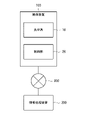
- the system shown in FIG. 9 has an imaging device 100 , an information processing device 200 , and a network 300 .
- the imaging device 100 has the optical system 10 and the control unit 20 described above.
- the imaging device 100 is, for example, a camera.
- the control unit 20 acquires imaging data (or imaging signals) output from the imaging element 11 provided in the optical system 10 and transmits the acquired imaging data to the information processing device 200 via the network 300 .
- the control unit 20 is, for example, a CPU (Central Processing Unit), a programmable device such as an FPGA (Field-Programmable Gate Array), or a GPU (Graphics Processing Unit), or one or more of them. circuit and so on.
- the information processing device 200 executes face authentication processing, iris authentication processing, or both, based on the received imaging data.
- the information processing apparatus 200 may perform object recognition processing other than face authentication processing and iris authentication processing.
- the information processing apparatus 200 is, for example, a CPU, a programmable device such as an FPGA, a GPU, or a circuit equipped with one or more of them, a server computer, a personal computer, a mobile terminal, or the like.
- the information processing apparatus 200 is configured to perform face authentication processing, iris authentication processing, or both, but the control unit 20 may be configured to perform the above-described processing. .
- the network 300 is constructed using communication lines such as the Internet, LAN (Local Area Network), leased line, telephone line, corporate network, mobile communication network, Bluetooth (registered trademark), and WiFi (Wireless Fidelity). general network.
- communication lines such as the Internet, LAN (Local Area Network), leased line, telephone line, corporate network, mobile communication network, Bluetooth (registered trademark), and WiFi (Wireless Fidelity). general network.
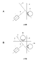
- FIGS. 10 and 11 are diagrams for explaining face authentication and iris authentication.
- the right eye portion (solid line) of the face can be focused as shown in FIG.
- the eye portion (dashed line) cannot be focused. Therefore, accurate face recognition and iris recognition cannot be performed.
- the right eye portion and the left eye portion can be focused as shown in FIG. can.
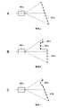
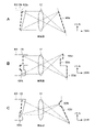
- FIGS. 12A, 12B, and 12C show an optical system having multiple and curved focusing surfaces.
- the optical system of A in FIG. 12 has two focal planes 16a and 16b. That is, the prism 13c as shown in FIG. 12A is focused on the subject on focusing planes 16a and 16b (dogleg-shaped focusing planes) oblique to the light receiving surface . Therefore, the shape of the prism 13c in FIG. 12A is such that the light receiving surface of the image sensor 11 as shown in A in FIG. It is designed so that the virtual image 15c of 14 can be formed in a doglegged shape.
- the optical system of B in FIG. 12 has a plurality of discontinuous focal planes 16c, 16d and 16e. That is, the prism 13d shown in FIG. 12B has a focusing surface 16c parallel to the light receiving surface 14, a focusing surface 16d different in depth from the focusing surface 16c, and a focusing surface 16d oblique to the light receiving surface 14. The object is brought into focus on the surface 16e. Therefore, the shape of the prism 13d in FIG. 12B is such that a virtual image of the light receiving surface 14 of the image sensor 11 as shown in FIG. It is designed so that 15d can be formed.
- the optical system of C in FIG. 12 has multiple focal planes 16f and 16g. That is, the prism 13e shown in FIG. 12C brings the object into focus on the focusing surface 16f parallel to the light receiving surface 14 and the curved focusing surface 16g. Therefore, the shape of the prism 13e in FIG. 12C is such that a virtual image 15e of the light receiving surface 14 of the image sensor 11 as shown in FIG. Designed to be formed.
- a prism capable of forming the virtual image 15 of the light receiving surface 14 of the image sensor 11 is used in the prism 13 having an image forming relationship with the focal plane, so that the optical system can be made compact.
- the shape of the prism 13 can be designed using only the above-described Equations 1 and 2, since the surface having an image forming relationship with the focusing surface 16 may be a virtual image. Therefore, the design is simple and the cost can be further reduced.
- the imaging device used for object recognition such as face recognition and iris recognition can be made smaller.
- the present invention may be applied to imaging devices used for applications other than object recognition, such as face authentication and iris authentication.
- a plurality of prisms having different shapes may be prepared in advance for each application, and the prisms may be exchanged according to the positional relationship between the optical system and the subject.
- the projection device that projects and displays the image on the projection surface can be miniaturized.
- a plurality of prisms having different shapes may be prepared in advance for each application, and the prisms may be exchanged according to the positional relationship between the optical system and the projection surface.
- FIG. 13 is a diagram for explaining an example of a system having the imaging device according to the second embodiment
- the system shown in FIG. 13 has an imaging device 100a, an information processing device 200, and a network 300.
- the system shown in FIG. Note that the information processing apparatus 200 and the network 300 have been described in the first embodiment, so description thereof will be omitted.
- the imaging device 100a has an optical system 101 and a control unit 102.
- the imaging device 100a is, for example, a camera.
- the optical system 101 has the same configuration as that of the first embodiment, but the shape of the prism portion included in the optical system 101 of the second embodiment can be changed. Details of the optical system 101 will be described later.
- FIG. 14 is a diagram for explaining the optical system of Embodiment 2.
- FIG. The optical system 101 has an imaging device 11 , a lens 12 and a prism section 402 . Note that the imaging element 11 and the lens 12 have been described in the first embodiment, so descriptions thereof will be omitted.
- the prism section 402 has a flat plate section 403a, a flat plate section 403b, an expandable section 404, an actuator 405a, and an actuator 405b. By changing the shape of the prism unit 402, the position of the focal plane can be changed.
- the flat plate portion 403a is provided and fixed in parallel with the light receiving surface 14 on the imaging element 11 side of the expandable portion 404 (the side opposite to the Z direction).
- the lens 12 side (Z direction side) of the flat plate portion 403a is adhered to the imaging element 11 side (Z direction side) of the expansion/contraction portion 404 .
- the flat plate portion 403b is provided on the lens 12 side (Z direction side) of the expandable portion 404. Further, the surface of the flat plate portion 403b on the imaging element 11 side (opposite direction to the Z direction) is adhered to the lens 12 side (Z direction side) of the expandable portion 404 .
- the material of the flat plate portions 403a and 403b is, for example, glass or plastic.
- the material of the flat plate portions 403a and 403b is not limited to glass and plastic, and various transparent materials having the same effect as glass and plastic may be used.
- the elastic portion 404 is provided between the flat plate portion 403a and the flat plate portion 403b, and is adhered to the flat plate portion 403a and the flat plate portion 403b at a predetermined position.
- the expansion/contraction part 404 is formed by filling a transparent bag-like medium (expandable material) that expands and contracts with liquid.
- the elastic material is, for example, silicone rubber.
- the stretchable material is not limited to silicone rubber, and any stretchable material having the same action as silicone rubber or the like may be used.
- Liquids are, for example, water and oil.
- the liquid is not limited to water and oil, and any liquid having the same action as water or oil may be used.
- the expansion/contraction part 404 has a refractive index.
- the flat plate portion 403a, the flat plate portion 403b, and the expandable portion 404 may have the same refractive index, or may have different refractive indexes.
- the actuator 405a is provided at one end (predetermined position) on the lens 12 side (Z direction side) of the flat plate portion 403b. Further, the actuator 405a is driven under the control of the control unit 102 to move one end of the flat plate portion 403b on the lens 12 side (Z direction side) in the Z direction or in a direction opposite to the Z direction.
- the position of actuator 405a is not limited to the position shown in FIG.
- the actuator 405b is provided at the other end (predetermined position) on the lens 12 side (Z direction side) of the flat plate portion 403b.
- the actuator 405b is driven by the control from the control unit 102 to move the other end of the flat plate portion 403b on the lens 12 side (Z direction side) in the Z direction or in the direction opposite to the Z direction.
- the position of actuator 405b is not limited to the position shown in FIG.
- the flat plate portion 403b is tilted by controlling the actuators 405a and 405b, and the shape of the expansion/contraction portion 404 is deformed.
- the expandable portion 404 is deformed into a shape as shown in FIG.
- FIG. 15 is a diagram for explaining the optical system of Embodiment 2.
- the actuator 405b is used to push and tilt the other end of the flat plate portion 403b in the direction opposite to the Z direction, thereby deforming the expandable portion 404 into a wedge shape.
- control unit 102 controls the actuators 405a and 405b to tilt the surface of the flat plate portion 403b based on preset conditions.
- the condition is a condition that the angle formed by the flat plate portion 403a and the flat plate portion 403b becomes the preset apex angle Ang.
- the expansion/contraction section 404 may be deformed according to the installation conditions of the imaging device 100a. Furthermore, the in-focus state of the subject may be detected by image processing, and the expansion/contraction unit 404 may be dynamically deformed according to the detected state.
- the actuators 405a and 405b are controlled to change the shape of the expansion/contraction portion 404.
- screws or the like may be used to manually move the plate portions 403a and 403b. good.
- FIG. 16 is a diagram for explaining an example of a system having the imaging device according to the third embodiment.
- the system shown in FIG. 16 has an imaging device 100b, an information processing device 200, and a network 300.
- the system shown in FIG. Note that the information processing apparatus 200 and the network 300 have been described in the first embodiment, so description thereof will be omitted.
- the imaging device 100b has an optical system 111 and a control unit 112.
- the imaging device 100b is, for example, a camera.
- the optical system 111 has the same configuration as that of the first embodiment, but the position of the focal plane can be changed by rotating the prism of the optical system 111 of the third embodiment. Details of the optical system 111 will be described later.
- the control unit 112 has the same configuration as in the first embodiment. However, the control unit 112 of the third embodiment further performs control for rotating the prism. Details of the control unit 112 will be described later.
- FIG. 17 is a diagram for explaining the optical system of Embodiment 3.
- FIG. The optical system 111 has an imaging device 11 , a lens 12 and a prism section 502 . Note that the imaging element 11 and the lens 12 have been described in the first embodiment, so descriptions thereof will be omitted.
- the prism unit 502 has a hollow shaft motor 503 and a prism 13f.
- the prism unit 502 can change the position of the focal plane by rotating the prism 13f using the hollow shaft motor 503. FIG.
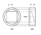
- the hollow shaft motor 503 rotates the cylindrical rotary hollow shaft 504 around the rotation axis of the rotary hollow shaft 504 to rotate the prism 13f.
- FIG. 18 is a diagram for explaining an example of the structure of the rotating hollow shaft.
- rotation axis shown in FIGS. 17 and 18 may coincide with the optical axis of the lens 12, or may be different from the rotation axis and the optical axis of the lens 12.
- FIG. 19 is a diagram for explaining the in-focus plane in the third embodiment.
- the focal plane moves (changes) at each time according to the rotation of the prism 13f.
- the in-focus plane 16h shown in FIG. 19A moves to the in-focus plane 16i shown in FIG. 19B after a predetermined time has elapsed.
- the prism 13f may be rotated or translated in accordance with the installation conditions of the imaging device 100b.
- the in-focus state of the object may be detected by image processing, and the object may be dynamically rotated or translated according to the detected state.
- the prism 13f may be translated or reciprocated in parallel other than rotation.
- FIG. 20 is a diagram for explaining an example of an optical system that the projection device has.
- the display element 601 is a device that displays an image.
- the display element 601 is, for example, a liquid crystal panel, various spatial light modulators such as a DMD. However, it is not limited to the liquid crystal panel and DMD described above.
- the resolution of the display element 601 it is conceivable to use a liquid crystal panel with horizontal 1920 pixels ⁇ vertical 1080 pixels, a pixel pitch of 10 [ ⁇ m], and a frame rate of 60 [fps]. However, it is not limited to the resolution, pixel pitch, and frame rate described above.
- the prism 13g is arranged between the optical path of the display element 601 and the lens 12.
- a virtual image 602 of the surface of the display element 601 is formed in the prism 13g.
- the projected surface 603 is positioned conjugate with the virtual image 602 via the lens 12 in the optical system 600 . That is, the projected surface 603 and the virtual image 602 are in an imaging relationship.
- the shape of the prism 13g is such that a virtual image 602 of the surface of the display element 601 is formed in the prism 13g in an image forming relationship with the projection surface 603 in order to focus the projection object on the projection surface 603. do.
- 21 and 22 are diagrams for explaining another prism example of the fourth embodiment. As shown in FIG. 21A, when the projected surface 603a is oblique to the optical system 600a provided in the projection apparatus, a wedge-shaped prism 13h as shown in FIG. 22A is used.
- the prism 13h as shown in A of FIG. 22 focuses the display element 601, which is the projection object, on the projection surface 603a. Therefore, the shape of the prism 13h in FIG. 22A is designed so that a virtual image 602a of the display element 601 as shown in FIG. .
- the projected surface of the optical system 600b provided in the projection apparatus is discontinuous projected surfaces 603b, 603c, and 603d having different depths.
- a prism 13i having a discontinuous surface is used.
- the prism 13i as shown in FIG. 22B focuses the display element 601, which is the projection object, on the projection surfaces 603b, 603c, and 603d. Therefore, the shape of the prism 13i in FIG. 22B can form a virtual image 602b of the display element 601 as shown in FIG. designed to
- the projected surface of the optical system 600c provided in the projection device is composed of a curved projected surface 603e and a projected projected surface 603f.
- a prism 13j having a is used.
- the prism 13j as shown in FIG. 22C focuses the display element 601, which is the projection object, on the projection surfaces 603e and 603f. Therefore, the shape of the prism 13j in FIG. 22C is such that a virtual image 602c of the display element 601 as shown in FIG. design.
- an image is projected by arranging the corresponding prism 13 on the display surface of the display element with respect to the oblique projection surface, the discontinuous projection surface, and the projection surface including the curved surface.
- a prism corresponding to each liquid crystal panel is arranged.
- optical system described in the second and third embodiments may be adopted as the optical system 600 of the fourth embodiment.
- a prism capable of forming the virtual image 602 of the display element 601 is used in the prism 13 having an image forming relationship with the projection surface, so that the optical system can be miniaturized.
- the shape of the prism 13 can be designed using only the above-described Equations 1 and 2, since the surface having an image forming relationship with the projected surface 603 may be a virtual image. Therefore, the design is simple and the cost can be further reduced.
- the projection device that projects and displays the image on the projection surface can be miniaturized.
- a plurality of prisms having different shapes may be prepared in advance for each application, and the prisms may be exchanged according to the positional relationship between the optical system and the projection surface.
- Appendix 1 an imaging device that converts light into an electrical signal; a lens that refracts and focuses light; a prism disposed between the optical path of the imaging element and the lens; An optical system in which a virtual image of the light receiving surface of the imaging element is formed in the prism, and a focal plane is positioned conjugate with the virtual image through the lens.
- the optical system according to Appendix 1 is A transparent first flat plate portion fixed to the imaging element side; a transparent second flat plate portion disposed on the lens side; a stretchable portion disposed between the first flat plate portion and the second flat plate portion, wherein a stretchable bag-like transparent medium is filled with a liquid; an actuator that tilts the second flat plate portion to change the shape of the expandable portion.
- Appendix 3 The optical system according to Appendix 1, having a hollow shaft motor that rotates a cylindrical rotating hollow shaft; The hollow shaft motor rotates the prism inside the rotating hollow shaft.
- Appendix 4 an imaging device that converts light into an electrical signal; a lens that refracts and focuses light; a prism disposed between the optical path of the imaging element and the lens; An image pickup apparatus, wherein a virtual image of the light receiving surface of the image sensor is formed in the prism, and a focal plane is positioned conjugate with the virtual image through the lens.
- the imaging device is A transparent first flat plate portion fixed to the imaging element side; a transparent second flat plate portion disposed on the lens side; a stretchable portion disposed between the first flat plate portion and the second flat plate portion, wherein a stretchable bag-like transparent medium is filled with a liquid; and an actuator that tilts the second flat plate portion to change the shape of the expandable portion.
- Appendix 6 The imaging device according to appendix 4, having a hollow shaft motor that rotates a cylindrical rotating hollow shaft; The imaging device, wherein the hollow shaft motor rotates the prism inside the rotary hollow shaft.
- (Appendix 7) a display element for displaying an image; a lens that refracts and focuses light; a prism disposed between the optical path of the display element and the lens; An optical system in which a virtual image of the surface of the display element is formed in the prism, and a projected surface is positioned conjugate with the virtual image through the lens.
- the optical system according to Appendix 7, The prism is A transparent first flat plate portion fixed to the display element side; a transparent second flat plate portion disposed on the lens side; a stretchable portion disposed between the first flat plate portion and the second flat plate portion, wherein a stretchable bag-like transparent medium is filled with a liquid; an actuator that tilts the second flat plate portion to change the shape of the expandable portion.
- Appendix 9 The optical system according to Appendix 7, having a hollow shaft motor that rotates a cylindrical rotating hollow shaft; The hollow shaft motor rotates the prism inside the rotating hollow shaft.
- Appendix 10 a display element for displaying an image; a lens that refracts and focuses light; a prism disposed between the optical path of the display element and the lens; A projection device in which a virtual image of the surface of the display element is formed in the prism, and a projected surface is positioned conjugate with the virtual image through the lens.
- the projection device is A transparent first flat plate portion fixed to the display element side; a transparent second flat plate portion disposed on the lens side; a stretchable portion disposed between the first flat plate portion and the second flat plate portion, wherein a stretchable bag-like transparent medium is filled with a liquid; and an actuator for tilting the second flat plate portion to change the shape of the telescoping portion.
- Appendix 12 The projection device according to Appendix 10, having a hollow shaft motor that rotates a cylindrical rotating hollow shaft; The hollow shaft motor rotates the prism inside the rotary hollow shaft.
- the present invention it is possible to provide a compact and inexpensive optical system capable of multiple focusing, and an imaging device and a projection device using the optical system.
- INDUSTRIAL APPLICABILITY The present invention is useful in fields requiring object recognition and image projection, such as face recognition and iris recognition.
- Imaging device 101, 111, 600 optical system 11 imaging device 12 lens 13 prism 14 light receiving surface 15, 602 virtual image 16 focusing surface 20, 102, 112 control unit 100 imaging device 200 information processing device 300 network 402, 502 prism unit 403 flat plate Part 404 Expandable part 405 Actuator 503 Hollow shaft motor 504 Rotating hollow shaft 601 Display element 603 Projected surface
Landscapes
- Physics & Mathematics (AREA)
- General Physics & Mathematics (AREA)
- Optics & Photonics (AREA)
- Engineering & Computer Science (AREA)
- Multimedia (AREA)
- Signal Processing (AREA)
- Optical Elements Other Than Lenses (AREA)
Priority Applications (3)
| Application Number | Priority Date | Filing Date | Title |
|---|---|---|---|
| JP2023526730A JP7616374B2 (ja) | 2021-06-09 | 2021-06-09 | 光学系、撮像装置、及び投射装置 |
| PCT/JP2021/021942 WO2022259428A1 (ja) | 2021-06-09 | 2021-06-09 | 光学系、撮像装置、及び投射装置 |
| US18/567,064 US12422667B2 (en) | 2021-06-09 | 2021-06-09 | Optical system, imaging apparatus, and projection apparatus |
Applications Claiming Priority (1)
| Application Number | Priority Date | Filing Date | Title |
|---|---|---|---|
| PCT/JP2021/021942 WO2022259428A1 (ja) | 2021-06-09 | 2021-06-09 | 光学系、撮像装置、及び投射装置 |
Publications (1)
| Publication Number | Publication Date |
|---|---|
| WO2022259428A1 true WO2022259428A1 (ja) | 2022-12-15 |
Family
ID=84425994
Family Applications (1)
| Application Number | Title | Priority Date | Filing Date |
|---|---|---|---|
| PCT/JP2021/021942 Ceased WO2022259428A1 (ja) | 2021-06-09 | 2021-06-09 | 光学系、撮像装置、及び投射装置 |
Country Status (3)
| Country | Link |
|---|---|
| US (1) | US12422667B2 (https=) |
| JP (1) | JP7616374B2 (https=) |
| WO (1) | WO2022259428A1 (https=) |
Families Citing this family (1)
| Publication number | Priority date | Publication date | Assignee | Title |
|---|---|---|---|---|
| DE102023111846A1 (de) * | 2023-05-05 | 2024-11-07 | Carl Zeiss Ag | Optisches System für eine Kamera und Kamera mit einem optischen System |
Citations (3)
| Publication number | Priority date | Publication date | Assignee | Title |
|---|---|---|---|---|
| JPS60176017A (ja) * | 1984-02-23 | 1985-09-10 | Canon Inc | 光学素子 |
| JP2005223897A (ja) * | 2004-01-07 | 2005-08-18 | Pentax Corp | 撮像装置および撮像機能を備えた電子機器 |
| JP2007094095A (ja) * | 2005-09-29 | 2007-04-12 | Olympus Imaging Corp | 投影型映像表示装置 |
Family Cites Families (11)
| Publication number | Priority date | Publication date | Assignee | Title |
|---|---|---|---|---|
| JPH05122451A (ja) | 1991-10-24 | 1993-05-18 | Seiko Epson Corp | イメージスキヤナ |
| JP3309615B2 (ja) * | 1994-12-21 | 2002-07-29 | キヤノン株式会社 | 画像観察装置及びこれを用いた両眼画像観察装置 |
| JP4329863B2 (ja) | 2007-02-14 | 2009-09-09 | コニカミノルタオプト株式会社 | 投影光学系及び画像投影装置 |
| JP6007757B2 (ja) | 2012-11-29 | 2016-10-12 | セイコーエプソン株式会社 | プロジェクター |
| JP6065630B2 (ja) * | 2013-02-13 | 2017-01-25 | セイコーエプソン株式会社 | 虚像表示装置 |
| WO2016035517A1 (ja) * | 2014-09-01 | 2016-03-10 | シャープ株式会社 | ライトガイドおよび虚像表示装置 |
| JP2018174362A (ja) | 2017-03-31 | 2018-11-08 | 日本電気株式会社 | 画像入力装置及び画像入力方法 |
| JP2019113794A (ja) * | 2017-12-26 | 2019-07-11 | ソニーセミコンダクタソリューションズ株式会社 | 画像表示装置及び表示装置 |
| JP2021033154A (ja) * | 2019-08-28 | 2021-03-01 | セイコーエプソン株式会社 | 虚像表示装置及び導光装置 |
| US20210263319A1 (en) * | 2020-02-25 | 2021-08-26 | Luminit Llc | Head-mounted display with volume substrate-guided holographic continuous lens optics |
| US11516391B2 (en) * | 2020-06-18 | 2022-11-29 | Qualcomm Incorporated | Multiple camera system for wide angle imaging |
-
2021
- 2021-06-09 JP JP2023526730A patent/JP7616374B2/ja active Active
- 2021-06-09 WO PCT/JP2021/021942 patent/WO2022259428A1/ja not_active Ceased
- 2021-06-09 US US18/567,064 patent/US12422667B2/en active Active
Patent Citations (3)
| Publication number | Priority date | Publication date | Assignee | Title |
|---|---|---|---|---|
| JPS60176017A (ja) * | 1984-02-23 | 1985-09-10 | Canon Inc | 光学素子 |
| JP2005223897A (ja) * | 2004-01-07 | 2005-08-18 | Pentax Corp | 撮像装置および撮像機能を備えた電子機器 |
| JP2007094095A (ja) * | 2005-09-29 | 2007-04-12 | Olympus Imaging Corp | 投影型映像表示装置 |
Also Published As
| Publication number | Publication date |
|---|---|
| US12422667B2 (en) | 2025-09-23 |
| US20240264431A1 (en) | 2024-08-08 |
| JPWO2022259428A1 (https=) | 2022-12-15 |
| JP7616374B2 (ja) | 2025-01-17 |
Similar Documents
| Publication | Publication Date | Title |
|---|---|---|
| KR102124773B1 (ko) | 광학 기판을 포함하는 다중 조리개 이미징 디바이스 | |
| EP3158395B1 (en) | Multi-camera system using folded optics free from parallax and tilt artifacts | |
| US7701643B2 (en) | Fluidic optical devices | |
| CN106662796B (zh) | 使用折射棱镜的折叠光学阵列相机 | |
| TWI311204B (en) | Micromirror array lens with free surface | |
| US20200204740A1 (en) | A module with a plurality of cameras for integration in a mobile device | |
| CN105917254A (zh) | 双焦镜头和包括双焦镜头的成像装置 | |
| JP2020523625A (ja) | 複数開口画像化装置、画像化システム、および複数開口画像化装置を提供する方法 | |
| WO2021017683A1 (zh) | 一种光学防抖装置及控制方法 | |
| TWI762355B (zh) | 成像裝置、相機模組與電子裝置 | |
| JP2012008301A (ja) | 体積走査型3次元映像表示装置 | |
| KR102146677B1 (ko) | 카메라 모듈 | |
| JP7616374B2 (ja) | 光学系、撮像装置、及び投射装置 | |
| WO2021179560A1 (zh) | 一种光学系统、电子设备以及显示装置 | |
| US7589916B2 (en) | Micromirror array with iris function | |
| KR102143631B1 (ko) | 줌 렌즈 및 이를 포함하는 촬상 장치 | |
| CN111948801A (zh) | 投影镜头及投影成像系统 | |
| JP2006251613A (ja) | 撮像レンズ装置 | |
| KR102941489B1 (ko) | 렌즈 광학계 및 이를 구비한 카메라 모듈 | |
| KR102069630B1 (ko) | 카메라 모듈 | |
| CN115480437A (zh) | 摄像模组和电子设备 | |
| KR20090123546A (ko) | 가동 광경로전환부를 구비하는 촬상 광학계 및 이를 채용한이동 통신 기기 | |
| TWI904185B (zh) | 光束掃描器 | |
| CN113507553A (zh) | 摄像头模组及其移动终端 | |
| TWM545257U (zh) | 光學鏡片組、成像鏡頭與電子裝置 |
Legal Events
| Date | Code | Title | Description |
|---|---|---|---|
| 121 | Ep: the epo has been informed by wipo that ep was designated in this application |
Ref document number: 21945104 Country of ref document: EP Kind code of ref document: A1 |
|
| WWE | Wipo information: entry into national phase |
Ref document number: 2023526730 Country of ref document: JP |
|
| WWE | Wipo information: entry into national phase |
Ref document number: 18567064 Country of ref document: US |
|
| NENP | Non-entry into the national phase |
Ref country code: DE |
|
| 122 | Ep: pct application non-entry in european phase |
Ref document number: 21945104 Country of ref document: EP Kind code of ref document: A1 |
|
| WWG | Wipo information: grant in national office |
Ref document number: 18567064 Country of ref document: US |