WO2022255306A1 - 空気調和装置 - Google Patents
空気調和装置 Download PDFInfo
- Publication number
- WO2022255306A1 WO2022255306A1 PCT/JP2022/021945 JP2022021945W WO2022255306A1 WO 2022255306 A1 WO2022255306 A1 WO 2022255306A1 JP 2022021945 W JP2022021945 W JP 2022021945W WO 2022255306 A1 WO2022255306 A1 WO 2022255306A1
- Authority
- WO
- WIPO (PCT)
- Prior art keywords
- heat
- air
- irradiation device
- air conditioner
- heat exchanger
- Prior art date
- Legal status (The legal status is an assumption and is not a legal conclusion. Google has not performed a legal analysis and makes no representation as to the accuracy of the status listed.)
- Ceased
Links
Images




Classifications
-
- F—MECHANICAL ENGINEERING; LIGHTING; HEATING; WEAPONS; BLASTING
- F24—HEATING; RANGES; VENTILATING
- F24F—AIR-CONDITIONING; AIR-HUMIDIFICATION; VENTILATION; USE OF AIR CURRENTS FOR SCREENING
- F24F1/00—Room units for air-conditioning, e.g. separate or self-contained units or units receiving primary air from a central station
- F24F1/0007—Indoor units, e.g. fan coil units
- F24F1/0059—Indoor units, e.g. fan coil units characterised by heat exchangers
- F24F1/0063—Indoor units, e.g. fan coil units characterised by heat exchangers by the mounting or arrangement of the heat exchangers
-
- F—MECHANICAL ENGINEERING; LIGHTING; HEATING; WEAPONS; BLASTING
- F24—HEATING; RANGES; VENTILATING
- F24F—AIR-CONDITIONING; AIR-HUMIDIFICATION; VENTILATION; USE OF AIR CURRENTS FOR SCREENING
- F24F1/00—Room units for air-conditioning, e.g. separate or self-contained units or units receiving primary air from a central station
- F24F1/0007—Indoor units, e.g. fan coil units
- F24F1/0071—Indoor units, e.g. fan coil units with means for purifying supplied air
-
- F—MECHANICAL ENGINEERING; LIGHTING; HEATING; WEAPONS; BLASTING
- F24—HEATING; RANGES; VENTILATING
- F24F—AIR-CONDITIONING; AIR-HUMIDIFICATION; VENTILATION; USE OF AIR CURRENTS FOR SCREENING
- F24F1/00—Room units for air-conditioning, e.g. separate or self-contained units or units receiving primary air from a central station
- F24F1/0007—Indoor units, e.g. fan coil units
- F24F1/0071—Indoor units, e.g. fan coil units with means for purifying supplied air
- F24F1/0076—Indoor units, e.g. fan coil units with means for purifying supplied air by electric means, e.g. ionisers or electrostatic separators
-
- F—MECHANICAL ENGINEERING; LIGHTING; HEATING; WEAPONS; BLASTING
- F24—HEATING; RANGES; VENTILATING
- F24F—AIR-CONDITIONING; AIR-HUMIDIFICATION; VENTILATION; USE OF AIR CURRENTS FOR SCREENING
- F24F11/00—Control or safety arrangements
- F24F11/70—Control systems characterised by their outputs; Constructional details thereof
-
- F—MECHANICAL ENGINEERING; LIGHTING; HEATING; WEAPONS; BLASTING
- F24—HEATING; RANGES; VENTILATING
- F24F—AIR-CONDITIONING; AIR-HUMIDIFICATION; VENTILATION; USE OF AIR CURRENTS FOR SCREENING
- F24F13/00—Details common to, or for air-conditioning, air-humidification, ventilation or use of air currents for screening
- F24F13/22—Means for preventing condensation or evacuating condensate
- F24F13/222—Means for preventing condensation or evacuating condensate for evacuating condensate
-
- F—MECHANICAL ENGINEERING; LIGHTING; HEATING; WEAPONS; BLASTING
- F24—HEATING; RANGES; VENTILATING
- F24F—AIR-CONDITIONING; AIR-HUMIDIFICATION; VENTILATION; USE OF AIR CURRENTS FOR SCREENING
- F24F8/00—Treatment, e.g. purification, of air supplied to human living or working spaces otherwise than by heating, cooling, humidifying or drying
- F24F8/20—Treatment, e.g. purification, of air supplied to human living or working spaces otherwise than by heating, cooling, humidifying or drying by sterilisation
- F24F8/22—Treatment, e.g. purification, of air supplied to human living or working spaces otherwise than by heating, cooling, humidifying or drying by sterilisation using UV light
-
- F—MECHANICAL ENGINEERING; LIGHTING; HEATING; WEAPONS; BLASTING
- F24—HEATING; RANGES; VENTILATING
- F24F—AIR-CONDITIONING; AIR-HUMIDIFICATION; VENTILATION; USE OF AIR CURRENTS FOR SCREENING
- F24F6/00—Air-humidification, e.g. cooling by humidification
- F24F2006/006—Air-humidification, e.g. cooling by humidification with water treatment
-
- F—MECHANICAL ENGINEERING; LIGHTING; HEATING; WEAPONS; BLASTING
- F24—HEATING; RANGES; VENTILATING
- F24F—AIR-CONDITIONING; AIR-HUMIDIFICATION; VENTILATION; USE OF AIR CURRENTS FOR SCREENING
- F24F2221/00—Details or features not otherwise provided for
- F24F2221/17—Details or features not otherwise provided for mounted in a wall
Definitions
- the present disclosure relates to an air conditioner.
- Patent Document 1 a device such as a Peltier device is required to cool the LED, which complicates the configuration of the device.
- An object of the present disclosure is to enable LEDs to be cooled with a simple configuration.
- a first aspect comprises an irradiation device (70) having an LED (72) for irradiating ultraviolet rays, and a heat radiating section (F, 91, 92) for releasing heat of the irradiation device (70) to the air. It is an air conditioner.
- the LED (72) when the LED (72) generates heat, the heat radiation part (F, 91, 92) releases the heat of the irradiation device (70) to the air. Therefore, the LED (72) can be cooled with a simple configuration.
- a second aspect is, in the first aspect, a heat exchanger (40) having a plurality of fins (F) as the heat radiating section and exchanging heat between air and a heat medium, and the irradiation device (70). and a heat conducting part (75) connecting the fins (F).
- the LED (72) when the LED (72) generates heat, this heat is transferred from the irradiation device (70) to the fins (F) of the heat exchanger (40) via the heat conducting portion (75). Since the fins (F) have a relatively large heat transfer area, the heat of the LED can be released to the air through the fins (F).
- a third aspect in the second aspect, includes a control section (100) that turns on the irradiation device (70) during cooling operation in which air is cooled by the heat exchanger (40).
- the heat of the LED (72) can be transferred to the heat medium through the heat conducting portion (75) and the fins (F). can.
- a fourth aspect is the second or third aspect, further comprising a controller (100) that turns on the irradiation device (70) during heating operation in which air is heated by the heat exchanger (40). .
- the heat of the LED (72) can be transferred to the heat medium through the heat conducting portion (75) and the fins (F). can. Since the temperature of the LED (72) is higher than the temperature of the heat medium during the heating operation, the temperature rise of the LED (72) can be suppressed.
- the output of the irradiation device (70) during cooling operation in which air is cooled by the heat exchanger (40) is 40) for heating the air to a higher output than the output of the irradiation device (70) during heating operation.
- cooling operation is generally performed under high temperature and high humidity conditions, bacteria and mold are likely to grow inside the air conditioner (10).
- the output of the irradiation device (70) is relatively large during cooling operation, the generation of these bacteria and molds can be suppressed.
- the temperature of the fins (F) during cooling operation is lower than that during heating operation. Therefore, heat generation of the irradiation device (70) can be more effectively suppressed during cooling operation. As a result, the output of the LED (72) of the irradiation device (70) can be increased during cooling.
- a controller (100) is provided that turns on the irradiation device (70) when the operation of the air conditioner (10) is stopped.
- the irradiation device (70) is turned on when the operation of the air conditioner (10) is stopped, so the generation of these bacteria and molds can be suppressed.
- a drain pan (60) is provided, and the irradiation device (70) irradiates the ultraviolet rays toward the drain pan (60).
- the drain pan (60) can be sterilized by the ultraviolet rays emitted by the LED (72). This can suppress the growth of bacteria and mold in the drain pan (60).
- the irradiation device (70) irradiates the ultraviolet rays toward the heat exchanger (40).
- the heat exchanger (40) can be sterilized by ultraviolet light emitted from the LED (72). As a result, the heat exchanger (40) can be inhibited from generating bacteria and mold.
- a ninth aspect according to any one of the second to eighth aspects is provided with a fan (50) that conveys air, and the irradiation device (70) moves toward the air conveyed by the fan (50). Irradiate with UV rays.
- the air can be sterilized by the ultraviolet rays emitted by the LED (72). As a result, sterilized air can be supplied to the air-conditioned space.
- the heat exchanger (40) is configured to cool air with the heat medium
- the irradiation device (70) is configured to cool the heat It is arranged upstream of the air flow from the exchanger (40).
- Condensed water is generated in the heat exchanger (40) due to cooling of the air.
- the LED (72) faces the downstream side of the air flow.
- a twelfth aspect is any one of the second to eleventh aspects, wherein the heat conducting portion (75) is a part of the fin (F).
- the fins (F) also serve as the heat conducting portion (75), the number of parts can be reduced.
- a thirteenth aspect in the first aspect, comprises a heat conducting portion (75) connecting the irradiation device (70) and the heat radiating portion (F, 91, 92).
- At least one of the heat radiating portion (F, 91, 92) and the heat conducting portion (75) is made of a metal material.
- At least one of the heat radiating portion (F, 91, 92) and the heat conducting portion (75) is made of a metal material and has excellent thermal conductivity, so that the heat of the LED (72) is quickly released to the air. can.
- At least one of the heat conducting portion (75) and the heat conducting portion (75) has a thermal conductivity of 80 w/m ⁇ K or more.
- the heat of the LED (72) can be quickly released to the air.
- a casing (31) having an air passage (34) formed therein is provided, and the heat radiating portion (F, 91, 92) It includes a first heat radiating member (91) fixed to the inner surface of (31).
- the heat of the irradiation device (70) is released to the air via the first heat radiation member (91) fixed to the inner surface of the casing (31). Since the installation area for the first heat radiation member (91) can be secured on the inner surface of the casing (31), the heat radiation area of the heat radiation part (F, 91, 92) can be expanded, and the heat radiation of the heat radiation part (F, 91, 92) can be increased. can improve performance.
- the first heat radiation member (91) includes a metal plate or a metal tape.
- the heat radiation portions (F, 91, 92) can be easily formed on the inner surface of the casing (31).
- a casing (31) having an air passage (34) formed therein is provided, and the heat radiating portion (F, 91, 92) (31) includes a second heat dissipating member (92) constituted by a portion of (31).
- the casing (31) also serves as the heat radiating section (F, 91, 92), the number of parts can be reduced.
- FIG. 1 is a schematic piping system diagram of an air conditioner according to an embodiment.
- FIG. 2 is a longitudinal sectional view showing the internal structure of the indoor unit.
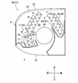
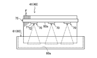
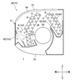
- FIG. 3 is a schematic diagram of the mounting structure of the irradiation device as viewed from the front side.
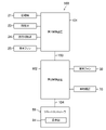
- FIG. 4 is a block diagram of an air conditioner.
- FIG. 5 is a diagram corresponding to FIG. 1 according to Modification 1.
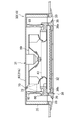
- FIG. 6 is a longitudinal sectional view showing the internal structure of an indoor unit according to Modification 3.
- FIG. FIG. 7 is a schematic configuration diagram of a heat conducting portion and fins according to a first example of modification 5.
- FIG. 8 is a schematic configuration diagram of a heat conducting portion and fins according to a second example of modification 5.
- FIG. 9 is a vertical cross-sectional view showing the internal structure of the indoor unit of Modification 6.
- FIG. 10 is a vertical cross-sectional view showing the internal structure of the indoor unit of Modification 7.
- FIG. 11 is a vertical cross-sectional view showing the internal structure of the indoor unit of Modification 8.
- FIG. 1 is a schematic piping system diagram of an air conditioner (10).
- the air conditioner (10) adjusts the temperature of the air in the target space.
- the target space is the indoor space (I).
- the air conditioner (10) performs cooling operation and heating operation. In cooling operation, the air conditioner (10) cools the air in the indoor space (I). In heating operation, the air conditioner (10) heats the air in the indoor space (I).
- the air conditioner (10) has a refrigerant circuit (11).
- the refrigerant circuit (11) is filled with refrigerant.
- the refrigerant circuit (11) performs a refrigeration cycle by circulating refrigerant.
- the refrigerant is, for example, R32 (difluoromethane).
- the air conditioner (10) includes an outdoor unit (20), an indoor unit (30), a first communication pipe (12), and a second communication pipe (13).
- the air conditioner (10) of this example is of a pair type having one outdoor unit (20) and one indoor unit (30).
- the outdoor unit (20) includes a compressor (21), an outdoor heat exchanger (22), an expansion valve (23), a four-way switching valve (24), and an outdoor fan (25).
- the indoor unit (30) includes an indoor heat exchanger (40) and an indoor fan (50).
- the first communication pipe (12) and the second communication pipe (13) connect the indoor unit (30) and the outdoor unit (20) to each other.
- the first communication pipe (12) is a gas pipe
- the second communication pipe (13) is a liquid pipe.
- the first communication pipe (12) is connected to the gas end of the indoor heat exchanger (40).
- the second communication pipe (13) is connected to the liquid end of the indoor heat exchanger (40).
- the air conditioner (10) has an irradiation device (70).
- the irradiation device (70) irradiates ultraviolet rays to disinfect a predetermined target.
- the compressor (21) compresses refrigerant.
- the compressor (21) is a rotary compressor.
- the rotary compressor (21) is configured by an oscillating type, a rolling piston type, a scroll type, or the like.
- the outdoor heat exchanger (22) exchanges heat between the refrigerant and the outdoor air.
- the outdoor heat exchanger (22) is of the fin and tube type.
- the outdoor fan (25) conveys outdoor air. Air carried by the outdoor fan (25) passes through the outdoor heat exchanger (22).
- the outdoor fan (25) is a propeller fan.
- the expansion valve (23) reduces the pressure of the refrigerant.
- the expansion valve (23) is an electronic or temperature sensitive expansion valve.
- the four-way switching valve (24) reverses the flow of refrigerant in the refrigerant circuit (11).
- the four-way switching valve (24) switches between a first state indicated by solid lines in FIG. 1 and a second state indicated by broken lines in FIG.
- the four-way switching valve (24) in the first state communicates the discharge side of the compressor (21) with the gas side of the outdoor heat exchanger (22), and at the same time, exchanges heat with the suction side of the compressor (21). communicate with the gas side of the vessel (40).
- the four-way switching valve (24) in the second state allows communication between the discharge side of the compressor (21) and the gas side of the indoor heat exchanger (40), and at the same time exchanges heat with the suction side of the compressor (21). communicate with the gas side of the vessel (22).
- FIG. 2 is a longitudinal sectional view of the indoor unit (30).
- the terms “top”, “bottom”, “front”, and “back” are based on the directions indicated by the arrows in FIG.
- the indoor unit (30) is installed in the indoor space (I).
- the indoor unit (30) is provided on the wall surface.
- the indoor unit (30) is a wall-mounted air conditioning indoor unit.
- the indoor unit (30) includes a casing (31), a filter (38), an indoor heat exchanger (40), an indoor fan (50), and a drain pan (60).
- the casing (31) forms an outer shell of the indoor unit (30).
- a suction port (32) is formed in the upper portion of the casing (31).
- An outlet (33) is formed in the lower portion of the casing (31).
- An air passage (34) is formed inside the casing (31) from the inlet (32) to the outlet (33).
- the suction port (32) takes indoor air in the indoor space (I) into the air passageway (34).
- the blowout port (33) blows out the air in the air passageway (34) into the indoor space (I).
- the outlet (33) is provided with a flap (not shown) for adjusting the direction of the blown air.
- a filter (38), an indoor heat exchanger (40), and an indoor fan (50) are arranged in the air passage (34) in this order from the upstream side to the downstream side of the air flow.
- the filter (38) is arranged upstream of the indoor heat exchanger (40) in the internal flow path (S1).
- the filter (38) collects dust and the like in the air sent from the suction port (32) to the indoor heat exchanger (40).
- the indoor unit may include a dust removing mechanism for removing dust adhering to the filter (38).
- the indoor heat exchanger (40) exchanges heat between a refrigerant, which is a heat medium, and air.
- the indoor heat exchanger (40) is of the fin-and-tube type.
- the indoor heat exchanger (40) includes a first heat exchanger (41) and a second heat exchanger (42).
- the first heat exchanger (41) is arranged in front of the indoor fan (50).
- the second heat exchanger (42) is arranged behind the indoor fan (50).
- the first heat exchanger (41) and the second heat exchanger (42) are configured separately from each other.
- the first heat exchanger (41) and the second heat exchanger (42) are composed of a plurality of fins (41) and heat transfer tubes ( 42) and respectively.
- the fin (F) is formed in a vertically long rectangular plate shape.
- the fins (F) are made of a metal material such as aluminum with high thermal conductivity.
- the heat transfer tube (P) is made of a metal material with high thermal conductivity such as copper.
- a fin (F) is an example of a heat dissipation part.
- the radiator radiates the heat of the irradiation device (70) to the air.
- the heat radiation part of the present embodiment further releases the heat of the irradiation device (70) to the coolant.
- the thermal conductivity of the fins (F) is preferably 80 W/m ⁇ K or more, more preferably 100 W/m ⁇ K or more.
- the indoor fan (50) conveys the indoor air.
- the indoor fan (50) is a cross-flow fan. Air conveyed by the indoor fan (50) passes through the indoor heat exchanger (40). The air that has passed through the indoor heat exchanger (40) is supplied to the indoor space (I) through the outlet (33).
- the drain pan (60) is a tray that receives condensed water in the air.
- the drain pan (60) includes a first drain pan (61) and a second drain pan (62).
- the first drain pan (61) is arranged below the first heat exchanger (41).
- the first drain pan (61) is located below the lower end of the first heat exchanger (41).
- the first drain pan (61) receives condensed water generated around the first heat exchanger (41).
- the second drain pan (62) is arranged below the second heat exchanger (42).
- the second drain pan (62) is located below the lower end of the second heat exchanger (42).
- the second drain pan (62) receives condensed water generated around the second heat exchanger (42).
- the irradiation device (70) is provided in the indoor unit (30).
- the irradiation device (70) is arranged inside the casing (31).
- the irradiation device (70) of this example targets the first drain pan (61) and air.
- the irradiation device (70) has a circuit board (71) and an LED (72).
- the LED (72) is provided on the circuit board (71).
- the LED (72) is a light emitting part that emits ultraviolet light.
- the LED (72) emits ultraviolet light with a predetermined directivity.
- the wavelength of ultraviolet rays emitted from the LED (72) is 190 nm or more and 280 nm or less. It is preferable that the wavelength of the ultraviolet rays is 220 mm or more and 270 nm or less.
- the air conditioner (10) of this example has three irradiation devices (70).
- the air conditioner (10) has a heat conducting part (75).
- the heat conducting part (75) of this example is made of a metal material. Metal materials include aluminum, stainless steel, or iron.
- the thermally conductive portion (75) may be made of a resin material having thermal conductivity. Examples of resin materials include polycarbonate, polybutylene terephthalate, polyacetal, and polyamide.
- the thermal conductivity of the heat conducting portion (75) is preferably 80 W/m ⁇ K or more, more preferably 100 W/m ⁇ K or more.
- the heat conducting part (75) connects the irradiation device (70) and the indoor heat exchanger (40).
- the heat conducting part (75) of this example is connected to the plurality of fins (F) of the first heat exchanger (41).
- the heat conducting part (75) is in contact with the endmost fin (end plate) of the first heat exchanger (41) and the side edges of the plurality of fins (F).
- the heat conducting part (75) extends along the front edges of the fins (F) in the direction in which the fins (F) are arranged so as to be in contact with all the fins (F) of the first heat exchanger (41). extended.
- the heat-conducting portion (75) may contact only a portion of all the fins (F).
- the irradiation device (70) is fixed to the lower part of the heat conducting part (75).
- the three irradiation devices (70) are arranged along the longitudinal direction of the heat conducting section (75).
- a circuit board (71) is fixed to the heat conducting portion (75).
- the LED (72) is thermally connected to the heat conducting portion (75) through the circuit board (71).
- the heat conducting portion (75) may be in direct contact with the LED (72).
- the LED (72) emits ultraviolet rays toward the first drain pan (61). Specifically, the LED (72) emits ultraviolet light toward the bottom surface (60a) of the first drain pan (61). As a result, the first drain pan (61) and the water inside the first drain pan (61) can be sterilized by the ultraviolet rays.
- the LED (72) irradiates ultraviolet rays toward the air carried by the indoor fan (50). In other words, the LED (72) emits ultraviolet rays toward the air in the air passageway (34). Thereby, the air supplied to the indoor space (I) can be sterilized.
- the heat conducting portion (75) is positioned upstream of the LEDs (72), and the LEDs (72) are fixed to the downstream surface (lower surface) of the heat conducting portion (75). Therefore, the heat conducting portion (75) can prevent dust in the air from adhering to the surface of the LED (72).
- Condensed water generated around the indoor heat exchanger (40) may scatter downstream of the indoor heat exchanger (40).
- the irradiation device (70) and the heat transfer section (75) are arranged upstream of the air flow in the first heat exchanger (41). Therefore, it is possible to suppress adhesion of condensed water to the LEDs (72) and the circuit board (71) of the irradiation device (70).
- the air conditioner (10) includes a remote controller (80).
- the remote controller (80) has an operation section (81).
- the operating section (81) is a functional section for a person to input various instructions to the air conditioner (10).
- the operation unit (81) includes switches, buttons, or a touch panel. Operation of the air conditioner (10) is selected by a person operating the operation unit (81).
- the operation of the air conditioner (10) includes cooling operation and heating operation.
- the air conditioner (10) has a control section (100).
- the control section (100) controls the operation of the air conditioner (10).
- the controller (100) controls the operation of the irradiation device (70).
- the control unit (100) includes a first control device (101), a second control device (102), a remote controller (80), a first communication line (103), and a second communication line (104).
- Each of the first controller (101) and the second controller (102) includes an MCU (Micro Control Unit), an electric circuit, and an electronic circuit.
- the MCU includes a CPU (Central Processing Unit), memory, and a communication interface. Various programs for the CPU to execute are stored in the memory.
- the first control device (101) is provided in the outdoor unit (20).
- the second control device (102) is provided in the indoor unit (30).
- the first control device (101) and the second control device (102) are connected to each other via a first communication line (103).
- the second control device (102) and the remote controller (80) are connected to each other via a second communication line (104).
- the first communication line (103) and the second communication line (104) are wired or wireless.
- the first controller (101) controls the compressor (21), the expansion valve (23), the four-way switching valve (24), and the outdoor fan (25) according to the received command.
- the second controller (102) controls the indoor fan (50) and the irradiation device (70) according to the received command.
- the control unit (100) switches between cooling operation and heating operation according to the received command.
- the control section (100) turns on the irradiation device (70) during cooling operation.
- the controller (100) of the present example turns on the irradiation device (70) during the heating operation.
- the control unit (100) makes the output of the irradiation device (70) during cooling operation higher than the output of the irradiation device (70) during heating operation.
- the control unit (100) makes the emission intensity of the irradiation device (70) during cooling operation higher than the emission intensity of the irradiation device (70) during heating operation.
- the operating behavior of the air conditioner (10) will be described in detail.
- the air conditioner (10) switches between cooling operation and heating operation.
- the control section (100) sets the four-way switching valve (24) to the first state.
- the controller (100) operates the compressor (21), the outdoor fan (25), and the indoor fan (50).
- the control section (100) adjusts the degree of opening of the expansion valve (23).
- the refrigerant circuit (11) performs a refrigeration cycle (cooling cycle) in which the outdoor heat exchanger (22) functions as a radiator and the indoor heat exchanger (40) functions as an evaporator.
- the refrigerant compressed by the compressor (21) flows through the outdoor heat exchanger (22).
- the outdoor heat exchanger (22) exchanges heat between refrigerant and outdoor air.
- the refrigerant that has released heat or condensed in the outdoor heat exchanger (22) is decompressed by the expansion valve (23) and then flows through the indoor heat exchanger (40).
- the indoor heat exchanger (40) exchanges heat between the refrigerant and indoor air.
- the refrigerant evaporated in the indoor heat exchanger (40) is compressed again in the compressor (21).
- indoor air is sucked into the air passage (34) through the suction port (32).
- Air in the air passageway (34) passes through the indoor heat exchanger (40).
- the indoor heat exchanger (40) cools air with refrigerant.
- the air cooled by the indoor heat exchanger (40) is supplied to the indoor space (I) through the outlet (33).
- the controller (100) sets the four-way switching valve (24) to the second state.
- the controller (100) operates the compressor (21), the outdoor fan (25), and the indoor fan (50).
- the control section (100) adjusts the degree of opening of the expansion valve (23).
- the refrigerant circuit (11) performs a refrigeration cycle (heating cycle) in which the indoor heat exchanger (40) functions as a radiator and the outdoor heat exchanger (22) functions as an evaporator.
- the refrigerant compressed by the compressor (21) flows through the indoor heat exchanger (40).
- the indoor heat exchanger (40) exchanges heat between the refrigerant and indoor air.
- the refrigerant that has released heat or condensed in the indoor heat exchanger (40) is decompressed by the expansion valve (23) and then flows through the outdoor heat exchanger (22).
- the outdoor heat exchanger (22) exchanges heat between refrigerant and outdoor air.
- the refrigerant evaporated in the outdoor heat exchanger (22) is compressed again in the compressor (21).
- indoor air is sucked into the air passage (34) through the suction port (32).
- Air in the air passageway (34) passes through the indoor heat exchanger (40).
- the indoor heat exchanger (40) heats air with refrigerant.
- the air heated by the indoor heat exchanger (40) is supplied to the indoor space (I) through the outlet (33).
- the controller (100) turns on the irradiation device (70).
- the LED (72) emits ultraviolet rays.
- the ultraviolet rays are applied to the first drain pan (61).
- the first drain pan (61) and the water in the first drain pan (61) can be sterilized. Therefore, propagation of bacteria and fungi in the first drain pan (61) can be suppressed.
- the ultraviolet rays irradiate the air flowing through the air passage (34). Therefore, the air flowing through the air passageway (34) can be sterilized, and the sterilized air can be supplied indoors.
- the control unit (100) makes the emission intensity of the irradiation device (70) during cooling operation higher than the emission intensity of the irradiation device (70) during heating operation. Cooling operation is performed under high temperature and high humidity conditions. Therefore, bacteria and the like tend to grow inside the casing (31) during cooling operation. On the other hand, by increasing the emission intensity of the irradiation device (70) during the cooling operation, the propagation of such bacteria can be reliably suppressed.
- the temperature of the fins (F) during cooling operation is lower than that during heating operation. Therefore, heat generation of the irradiation device (70) can be more effectively suppressed during cooling operation. As a result, the output of the LED (72) of the irradiation device (70) can be increased during cooling.
- the control unit (100) turns on the irradiation device (70).
- the LED (72) emits ultraviolet rays.
- the ultraviolet rays irradiate the air flowing through the air passageway (34). Therefore, the air flowing through the air passageway (34) can be sterilized, and the sterilized air can be supplied indoors.
- control unit (100) appropriately performs the reverse cycle defrost operation.
- the indoor heat exchanger (40) functions as an evaporator, so that condensation water may occur.
- the drain pan (60) receives this condensed water.
- the water irradiated by the LED (72) is irradiated to the first drain pan (61). Therefore, the first drain pan (61) and the water in the first drain pan (61) can be sterilized. Therefore, it is possible to suppress the propagation of bacteria and fungi in the first drain pan (61) due to the reverse cycle defrosting operation.
- the air conditioner (10) has fins (F) as heat radiators that release heat from the irradiation device (70) to the air. Therefore, the temperature rise of the LED (72) can be suppressed with a relatively simple configuration.
- the air conditioner (10) has a heat conducting part (75) that connects with the fins (F). Therefore, the heat generated from the LED (72) can be transferred to the fins (F) through the heat conducting portion (75). Therefore, the temperature rise of the LED (72) can be suppressed by the heat dissipation effect of the fins (F). This allows the irradiation device (70) to perform desired operations.
- the fins (F) are provided in the indoor heat exchanger (40) and have a sufficient heat transfer area, so they can effectively suppress the heat generation of the LEDs (72).
- the heat conducting portion (75) is made of a metal material, the heat of the irradiation device (70) can be rapidly transferred to the fins (F) via the heat conducting portion (75). Therefore, it is possible to prevent a decrease in the heat dissipation effect of the LED (72) due to the rate-determining heat transfer of the heat conducting portion (75).
- the thermal conductivity of the heat conductive portion (75) is 80 W/m ⁇ K or more, the heat dissipation effect of the LED (72) can be improved.
- the thermal conductivity of the heat conducting portion (75) to 100 W/m ⁇ K or more, the heat dissipation effect of the LED (72) can be sufficiently obtained.
- the heat dissipation effect of the LED (72) can be improved by setting the thermal conductivity of the fins (F) as the heat dissipation part to 80 W/m ⁇ K or more. In particular, by setting the thermal conductivity of the fins (F) to 100 W/m ⁇ K or more, a sufficient heat dissipation effect for the LEDs (72) can be obtained.
- the controller (100) turns on the irradiation device (70) in cooling operation. Therefore, it is possible to sterilize predetermined objects (air and drain pan (60)) under conditions where bacteria and mold are particularly likely to occur.
- the indoor heat exchanger (40) during cooling operation functions as an evaporator. Therefore, the LED (72) can be sufficiently cooled by the coolant.
- the controller (100) turns on the irradiation device (70) in the heating operation. Therefore, objects (air and drain pan (60)) can be sterilized even in heating operation.
- the irradiation device (70) is turned on, the temperature of the LED (72) may reach, for example, 80° C. or higher.
- the temperature of the refrigerant condensed in the indoor heat exchanger (40) is much lower than the temperature of the LED (72). Therefore, even in heating operation, the LED (72) can be sufficiently cooled by the refrigerant.
- the control unit (100) makes the emission intensity of the irradiation device (70) during cooling operation higher than the emission intensity of the irradiation device (70) during heating operation. Therefore, it is possible to reliably suppress the propagation of bacteria and fungi under conditions of high temperature and high humidity.
- the irradiation device (70) irradiates ultraviolet rays toward the drain pan (60). Therefore, the drain pan (60) and the water in the drain pan (60) can be sterilized.
- the irradiation device (70) irradiates the air conveyed by the fan (50) with ultraviolet rays. Therefore, sterilized air can be supplied to the indoor space (I).
- the irradiation device (70) is arranged upstream of the indoor heat exchanger (40) in the air flow. Therefore, it is possible to prevent the condensation water generated near the indoor heat exchanger (40) from adhering to the circuit board (71) and the LEDs (72), thereby compensating the operation of the irradiation device (70).
- the LED (72) faces the downstream side of the air flow. Therefore, it is possible to prevent dust in the air from adhering to the surface of the LED (72), and to prevent the substantial irradiation amount of the LED (72) from decreasing.
- Modification 1 Modification regarding target of irradiation device (7-1-1)
- the irradiation device (70) may irradiate the second drain pan (62) with ultraviolet rays.
- the irradiation device (70) may irradiate both the first drain pan (61) and the second drain pan (62) with ultraviolet rays.
- the irradiation device (70) may irradiate the indoor heat exchanger (40) with ultraviolet rays. Thereby, the surface of the indoor heat exchanger (40) can be sterilized.
- the irradiation device (70) irradiates the first heat exchanger (41) with ultraviolet rays.
- the heat conducting part (75) connects the irradiation device (70) and the first heat exchanger (41). In other words, the heat conducting part (75) connects the irradiation device (70) and the object of the irradiation device (70).
- the irradiation device (70) may irradiate the second heat exchanger (42) with ultraviolet rays. In this case, the heat conducting part (75) connects the irradiation device (70) and the second heat exchanger (42).
- the irradiation device (70) may irradiate the filter (38) with ultraviolet rays. Thereby, the surface and inside of the filter (38) can be sterilized.
- the irradiation device (70) may irradiate the dust removing mechanism of the filter (38) with ultraviolet rays.
- the irradiation device (70) may irradiate, of the air carried by the indoor fan (50), the air outside the casing (31) with ultraviolet rays. Specifically, the irradiation device (70) may irradiate the air sucked into the suction port (32) with ultraviolet rays. The irradiation device (70) may irradiate the air blown from the outlet (33) with ultraviolet rays.
- the irradiation device (70) may irradiate an indoor fan (50) as a fan with ultraviolet rays. Thereby, the indoor fan (50) can be sterilized.
- the irradiation device (70) may irradiate the inner wall of the casing (31) or the inner wall facing the air passageway (34) with ultraviolet rays. This allows these inner walls to be sterilized.
- the irradiation device (70) may be arranged downstream of the air flow in the indoor heat exchanger (40).
- the LED (72) may irradiate ultraviolet rays toward the upstream side of the airflow.
- the air conditioner (10) may have a ceiling-mounted indoor unit (30).
- the ceiling-mounted indoor unit (30) includes a ceiling-embedded type in which the indoor unit (30) is embedded in the ceiling surface, and a ceiling-mounted type in which the indoor unit (30) is suspended from the upper wall.
- FIG. 6 is a longitudinal sectional view of the indoor unit (30).
- the indoor unit (30) has a casing (31) installed above the ceiling.
- the casing (31) includes a casing body (35) and a panel (36).
- the casing body (35) is shaped like a rectangular box with an opening on the bottom.
- the panel (36) is detachably attached to the opening surface of the casing body (35).
- the panel (36) has a rectangular frame-shaped panel body (36a) and an intake grille (36b) provided in the center of the panel body (36a).
- One suction port (32) is formed in the center of the panel body (36a).
- the suction grille (36b) is attached to the suction port (32).
- Each of the four side edges of the panel body (36a) is formed with one outlet (33).
- Each outlet (33) extends along four side edges.
- a flap (39) is provided inside each outlet (33).
- An air passage (34) is formed in the casing (31) from the inlet (32) to the outlet (33).
- a bell mouth (43), an indoor fan (50), an indoor heat exchanger (40), and a drain pan (60) are provided inside the casing body (35).
- the bellmouth (43) and the indoor fan (50) are arranged above the intake grille (36b).
- the indoor fan (50) is a centrifugal turbo fan.
- the indoor heat exchanger (40) is arranged in the air passageway (34) so as to surround the indoor fan (50).
- the indoor heat exchanger (40) is a fin-and-tube heat exchanger.
- the drain pan (60) is arranged below the indoor heat exchanger (40) in the air passageway (34).
- the irradiation device (70) is arranged upstream of the indoor heat exchanger (40).
- the irradiation device (70) irradiates ultraviolet rays toward the drain pan (60).
- the heat conducting part (75) of this example connects the irradiation device (70) and the fins (not shown) of the indoor heat exchanger (40). Thereby, the heat of the LED (72) can be released to the air through the fins.
- the indoor unit (30) may be of a floor type or a duct type installed in the ceiling.
- the air conditioner (10) may have a function of ventilating the indoor space (I).
- the air conditioner (10) may have humidification and dehumidification functions.
- the air conditioner (10) may have a function of purifying air.
- the indoor unit (30) heat is exchanged between the refrigerant and air in the indoor heat exchanger (40).
- the indoor heat exchanger (40) may heat-exchange air with a heat medium other than refrigerant, such as water or brine.
- the air conditioner (10) may be of a multi-type having a plurality of indoor units (30).
- the air conditioner (10) may have a plurality of outdoor units (20).
- the control unit (100) may turn on the irradiation device (70) when the operation of the air conditioner (10) is stopped. Specifically, the control unit (100) may turn on the irradiation device (70) immediately after the cooling operation ends, for example. In this case, the irradiation device (70) irradiates the drain pan (60) with ultraviolet rays. Since condensed water tends to accumulate in the drain pan (60) immediately after the cooling operation ends, the water in the drain pan (60) can be reliably sterilized.
- the control section (100) may turn off the irradiation device (70) in the heating operation. Also in this case, the control unit (100) preferably makes the output of the irradiation device (70) during cooling operation higher than the output (zero) during heating operation.
- the control unit (100) may turn on the irradiation device (70) during the cooling operation of the cooling-only air conditioner (10).
- the controller (100) may turn on the irradiation device (70) during the heating operation of the air conditioner (10) dedicated to heating.
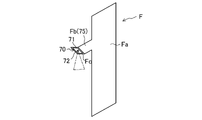
- FIG. 7 is a schematic diagram of the fin (F) viewed in the thickness direction.
- the fin (F) has a rectangular plate-shaped fin body (Fa) and a protrusion (Fb) integral with the fin body (Fa).
- the protrusion (Fb) protrudes outward from the widthwise end of the fin body (Fa).
- the fin body (Fa) and the protrusion (Fb) are integrally molded. Specifically, the fin body (Fa) and the protrusion (Fb) are integrally formed by press working.
- the projecting portion (Fb) is a heat conducting portion (75) that connects the irradiation device (70) and the fin body (Fa).
- the irradiation device (70) in the example of FIG. 7 is provided on the side surface of the protrusion (Fb).
- the heat conducting portion (75) is also used as part of the fins (F), so the number of parts can be reduced.
- the heat conducting portion (75) and the fins (F) are composed of one member, heat transfer from the heat conducting portion to the fin main body (Fa) is facilitated. As a result, the heat dissipation effect of the LED (72) is improved.
- a folded surface (Fc) is formed at the tip portion of the protrusion (Fb).
- the folded surface (Fc) is formed by bending the tip portion of the protrusion (Fb).
- the folded face (Fb) faces downward.
- the irradiation device (70) is provided on the folded surface (Fb). Thereby, ultraviolet rays can be emitted downward from the LED (72).
- a heat dissipation promotion part for promoting heat dissipation may be provided in the heat conduction part (75).
- the heat dissipation promoting part may be a heat sink or a heat pipe.
- the heat conducting part (75) may be made of any material having high heat conductivity, such as zinc, copper, or brass.
- the heat-conducting portion (75) does not necessarily have to be made of a metal material, and may be made of a carbon material such as graphite.
- Modification 6 First example in which a heat radiating part is provided on the inner surface of the casing
- the air conditioner (10) of Modification 6 has a wall-mounted indoor unit (30).
- a first heat radiation member (91) as a heat radiation section is provided on the inner surface of the casing (31) of the indoor unit (30).
- the casing (31) has a front plate (31a).
- the front plate (31a) constitutes the front surface of the casing (31).
- the front plate (31a) is made of a resin material.
- the first heat radiation member (91) is fixed to the inner surface of the front plate (31a).
- the first heat radiation member (91) is made of a material with high thermal conductivity.
- the first heat radiation member (91) of this example is made of a metal material.
- the first heat radiation member (91) is composed of a metal plate or metal tape. Note that the first heat radiation member (91) may be made of a resin material having high thermal conductivity.
- the first heat radiation member (91) extends along the inner surface of the front plate (31a).
- the first heat radiation member (91) faces the air passageway (34).
- the air flowing through the air passageway (34) flows along the first heat radiation member (91).
- the first heat radiation member (91) is arranged upstream of the heat exchanger (40) in the air flow.
- the first heat radiation member (91) may be fixed to the side plate of the casing (31).
- the side plates form lateral sides of the casing (31).
- the irradiation device (70) is fixed to the first heat radiation member (91) as a heat radiation section.
- the irradiation device (70) of this example is directly fixed to the first heat radiation member (91).
- Methods for directly fixing the irradiation device (70) to the heat radiating part include fixing by fastening with screws or the like, adhesion, fixing by fitting, and fixing by press-fitting. These fixing methods can also be employed in the above-described embodiment and other modifications.
- the irradiation device (70) may be fixed to the first heat radiation member (91) via the heat conducting portion (75) described above.
- the LED (72) of the irradiation device (70) of this example faces the downstream side of the air flow.
- the LED (72) irradiates the air flowing through the air passageway (34) with ultraviolet rays.
- the irradiation device (70) irradiates the indoor heat exchanger (40) and the drain pan (60) with ultraviolet rays.
- the control unit (100) may turn on the irradiation device (70) when the air conditioner (10) is stopped. Also in this case, the heat of the irradiation device (70) can be released to the air through the first heat radiation member (91).
- the installation space for the first heat radiation member (91) can be secured on the inner surface of the casing (31), it is easy to expand the area of the first heat radiation member (91). Therefore, the heat dissipation performance of the first heat dissipation member (91) can be improved.
- the air conditioner (10) of Modification 7 includes a wall-mounted indoor unit (30). have.
- a portion of the casing (31) of the indoor unit (30) constitutes a heat radiating section.
- at least part of the front plate (31a) of the casing (31) is composed of a second heat radiating member (92) with high thermal conductivity.
- the second heat dissipation member (92) is made of a metal material, but may be made of a resin material with high thermal conductivity.
- the second heat radiation member (92) is shaped like a plate facing the air passageway (34).
- the second heat radiation member (92) may be formed on the side plate of the casing (31).
- Other basic configurations of the air conditioner (10) of the seventh modification are the same as those of the sixth modification.
- the heat radiating portion is configured by part of the casing (31). Therefore, the number of parts can be reduced. Further, in this configuration, the heat transferred to the second heat radiation member (92) can be released not only to the air in the air passageway (34) but also to the air outside the casing (31). Therefore, the heat dissipation performance of the heat dissipation portion can be improved.
- Modification 8 Second example in which a part of the casing is a heat radiating part As shown in FIG. indoor unit (30). A portion of the casing (31) of the indoor unit (30) constitutes a heat radiating section. Specifically, at least part of the top plate (31b) of the casing (31) is composed of the second heat radiation member (92) with high thermal conductivity. The second heat radiation member (92) of the top plate (31b) faces the air passageway (34). The second heat radiation member (92) may be a side plate of the casing.
- the LED (72) of the irradiation device (70) faces downward.
- the irradiation device (70) irradiates the air passageway (34) with ultraviolet rays.
- the irradiation device (70) further irradiates the heat exchanger (40) and the drain pan (60) with ultraviolet rays.
- the heat radiating portion is configured by part of the casing (31). Therefore, the number of parts can be reduced. Since the top plate (31b) has a relatively large area compared to the side plates, the heat dissipation performance of the heat dissipation portion can be improved.
- the heat dissipating section may be provided on any component as long as it is made of a material with high heat transfer performance.
- the heat radiation part may be a drain pan made of metal or a resin material having thermal conductivity.
- the heat dissipation part may be a tube plate of the heat exchanger (40), a header collecting pipe of the heat exchanger (40), a flow divider, refrigerant pipes, or water pipes.
- the heat radiation section is preferably an element part of the air conditioner (10).
- the element parts are parts provided to achieve the original functions of the air conditioner (10). If it is an element part, since there is no need to separately provide a part for heat dissipation, the number of parts and cost can be reduced.
- the present disclosure is useful for air conditioners.
Landscapes
- Engineering & Computer Science (AREA)
- Chemical & Material Sciences (AREA)
- Combustion & Propulsion (AREA)
- Mechanical Engineering (AREA)
- General Engineering & Computer Science (AREA)
- Physics & Mathematics (AREA)
- Thermal Sciences (AREA)
- Air Filters, Heat-Exchange Apparatuses, And Housings Of Air-Conditioning Units (AREA)
- Central Air Conditioning (AREA)
- Air Conditioning Control Device (AREA)
- Devices For Blowing Cold Air, Devices For Blowing Warm Air, And Means For Preventing Water Condensation In Air Conditioning Units (AREA)
Abstract
Description
図1は、空気調和装置(10)の概略の配管系統図である。空気調和装置(10)は、対象空間の空気の温度を調節する。対象空間は室内空間(I)である。空気調和装置(10)は、冷房運転と暖房運転とを行う。冷房運転では、空気調和装置(10)が室内空間(I)の空気を冷却する。暖房運転では、空気調和装置(10)が室内空間(I)の空気を加熱する。
圧縮機(21)は、冷媒を圧縮する。圧縮機(21)は回転式の圧縮機である。回転式の圧縮機(21)は、揺動式、ローリングピストン式、スクロール式などで構成される。
図2は、室内機(30)の縦断面図である。以下の説明において、「上」、「下」、「前」、「後」に関する語句は、図2の矢印で示す方向を基準とする。
ケーシング(31)は、室内機(30)の外郭を形成している。ケーシング(31)の上部には、吸込口(32)が形成される。ケーシング(31)の下部には、吹出口(33)が形成される。ケーシング(31)の内部には、吸込口(32)から吹出口(33)に亘って空気通路(34)が形成される。吸込口(32)は、室内空間(I)の室内空気を空気通路(34)に取り込む。吹出口(33)は、空気通路(34)の空気を室内空間(I)に吹き出す。吹出口(33)には、吹出空気の風向を調節するフラップ(図示省略)が設けられる。
フィルタ(38)は、内部流路(S1)における室内熱交換器(40)の上流側に配置される。フィルタ(38)は、吸込口(32)から室内熱交換器(40)へ送られる空気中の塵埃などを捕集する。室内機は、フィルタ(38)に付着した塵埃を除去する塵埃除去機構を備えていてもよい。
室内熱交換器(40)は、熱媒体である冷媒と空気とを熱交換させる。室内熱交換器(40)は、フィンアンドチューブ式である。室内熱交換器(40)は、第1熱交換器(41)と第2熱交換器(42)とを含む。第1熱交換器(41)は、室内ファン(50)の前側に配置される。第2熱交換器(42)は、室内ファン(50)の後側に配置される。第1熱交換器(41)および第2熱交換器(42)は、互いに別体に構成される。
室内ファン(50)は、室内空気を搬送する。室内ファン(50)は、クロスフローファンである。室内ファン(50)により搬送される空気は、室内熱交換器(40)を通過する。室内熱交換器(40)を通過した空気は、吹出口(33)を通じて室内空間(I)へ供給される。
ドレンパン(60)は、空気中の結露水を受けるトレーである。ドレンパン(60)は、第1ドレンパン(61)と第2ドレンパン(62)とを含む。
図2に示すように、照射装置(70)は、室内機(30)に設けられる。照射装置(70)は、ケーシング(31)の内部に配置される。本例の照射装置(70)は、第1ドレンパン(61)および空気を対象とする。
図1および図4に示すように、空気調和装置(10)は、リモートコントローラ(80)を備える。リモートコントローラ(80)は、操作部(81)を有する。操作部(81)は、人が空気調和装置(10)に対する各種の指示を入力するための機能部である。操作部(81)は、スイッチ、ボタン、またはタッチパネルを含む。人が操作部(81)を操作することで空気調和装置(10)の運転が選択される。空気調和装置(10)の運転は、冷房運転と暖房運転とを含む。
空気調和装置(10)の運転動作について詳細に説明する。空気調和装置(10)は冷房運転と暖房運転とを切り換えて行う。
冷房運転では、制御部(100)が四方切換弁(24)を第1状態とする。制御部(100)は、圧縮機(21)、室外ファン(25)、および室内ファン(50)を運転する。制御部(100)は、膨張弁(23)の開度を調節する。冷房運転中の冷媒回路(11)は、室外熱交換器(22)が放熱器として機能し、室内熱交換器(40)が蒸発器として機能する冷凍サイクル(冷房サイクル)を行う。
暖房運転では、制御部(100)が四方切換弁(24)を第2状態とする。制御部(100)は、圧縮機(21)、室外ファン(25)、および室内ファン(50)を運転する。制御部(100)は、膨張弁(23)の開度を調節する。暖房運転中の冷媒回路(11)は、室内熱交換器(40)が放熱器として機能し、室外熱交換器(22)が蒸発器として機能する冷凍サイクル(暖房サイクル)を行う。
冷房運転時には、制御部(100)が照射装置(70)をON状態とする。照射装置(70)がON状態になると、LED(72)が紫外線を照射する。この紫外線は、第1ドレンパン(61)に照射される。これにより、第1ドレンパン(61)や第1ドレンパン(61)内の水を除菌できる。したがって、第1ドレンパン(61)における菌やカビの繁殖を抑制できる。
暖房運転時には、制御部(100)が照射装置(70)をON状態とする。照射装置(70)がON状態になると、LED(72)が紫外線を照射する。この紫外線は、空気通路(34)を流れる空気に照射される。このため、空気通路(34)を流れる空気を除菌し、除菌した空気を室内へ供給できる。
(6-1)空気調和装置(10)は、照射装置(70)の熱を空気へ放出する放熱部としてのフィン(F)を備える。このため、比較的簡単な構成により、LED(72)の温度上昇を抑制できる。
上記各実施形態においては、以下のような変形例の構成を採用してもよい。
(7-1-1)
照射装置(70)は、第2ドレンパン(62)に紫外線を照射してもよい。照射装置(70)は、第1ドレンパン(61)および第2ドレンパン(62)の双方に紫外線を照射してもよい。
図5に示すように、照射装置(70)は、室内熱交換器(40)に紫外線を照射してもよい。これにより、室内熱交換器(40)の表面を除菌できる。本例では、照射装置(70)は、第1熱交換器(41)に紫外線を照射する。熱伝導部(75)は、照射装置(70)と第1熱交換器(41)とを接続する。言い換えると、熱伝導部(75)は、照射装置(70)と、この照射装置(70)の対象とを接続する。照射装置(70)は、第2熱交換器(42)に紫外線を照射してもよい。この場合、熱伝導部(75)は、照射装置(70)と第2熱交換器(42)とを接続する。
照射装置(70)は、フィルタ(38)に紫外線を照射してもよい。これにより、フィルタ(38)の表面や内部を除菌できる。照射装置(70)は、フィルタ(38)の塵埃除去機構に紫外線を照射してもよい。
照射装置(70)は、室内ファン(50)によって搬送される空気のうち、ケーシング(31)の外部の空気に紫外線を照射してもよい。具体的には、照射装置(70)は、吸込口(32)に吸い込まれる空気に紫外線を照射してもよい。照射装置(70)は、吹出口(33)から吹き出される空気に紫外線を照射してもよい。
照射装置(70)は、ファンとしての室内ファン(50)に紫外線を照射してもよい。これにより、室内ファン(50)を除菌できる。
照射装置(70)は、ケーシング(31)の内壁や、空気通路(34)に面する内壁に紫外線を照射してもよい。これにより、これらの内壁を除菌できる。
照射装置(70)は、室内熱交換器(40)における空気流れの下流側に配置されてもよい。LED(72)は、空気流れの上流側に向かって紫外線を照射してもよい。
(7-3-1)
空気調和装置(10)は、天井設置式の室内機(30)を有してもよい。ここで、天井設置式の室内機(30)は、室内機(30)が天井面に埋め込まれる天井埋め込み式や、室内機(30)が上壁に吊り下げられる天井吊り式を含む。
室内機(30)は、床置き式や、天井裏に設置されるダクト式であってもよい。
室内機(30)では、室内熱交換器(40)において冷媒と空気を熱交換させる。しかし、室内熱交換器(40)は、水やブラインなどの冷媒以外の熱媒体と空気を熱交換させてもよい。
空気調和装置(10)は、複数の室内機(30)を有するマルチ式であってもよい。空気調和装置(10)は、複数の室外機(20)を有してもよい。
(7-4-1)
制御部(100)は、空気調和装置(10)の運転停止時において、照射装置(70)をON状態としてもよい。具体的には、制御部(100)は、例えば冷房運転の終了直後に照射装置(70)をON状態としてもよい。この場合、照射装置(70)は、ドレンパン(60)に向かって紫外線を照射する。冷房運転の終了直後には、ドレンパン(60)に結露水が溜まり易いため、ドレンパン(60)内の水を確実に除菌できる。
制御部(100)は、暖房運転において、照射装置(70)をOFF状態としもよい。この場合にも、制御部(100)は、冷房運転時の照射装置(70)の出力を、暖房運転時の出力(ゼロ)よりも大きくするとよい。
(7-5-1)
図7に示すように、熱伝導部(75)は、フィン(F)の一部であってもよい。図7は、フィン(F)を厚さ方向に見た模式図である。フィン(F)は、矩形板状のフィン本体(Fa)と、フィン本体(Fa)と一体の突起部(Fb)とを有する。突起部(Fb)は、フィン本体(Fa)の幅方向の端部から外方に突出している。フィン本体(Fa)と突起部(Fb)とは、一体に成形される。具体的には、フィン本体(Fa)と突起部(Fb)とは、プレス加工により一体に成形される。突起部(Fb)は、照射装置(70)とフィン本体(Fa)とを接続する熱伝導部(75)である。図7の例の照射装置(70)は、突起部(Fb)の側面に設けられている。
図8に示す例では、突起部(Fb)の先端部分に折り返し面(Fc)が形成される。折り返し面(Fc)は、突起部(Fb)の先端部分を折り曲げることで形成される。折り返し面(Fb)は、下方を向いている。照射装置(70)は、折り返し面(Fb)に設けられる。これにより、LED(72)から下方に向かって紫外線を照射できる。
熱伝導部(75)に放熱を促進する放熱促進部を設けてもよい。放熱促進部は、ヒートシンクやヒートパイプであってもよい。
熱伝導部(75)は、熱伝導率が高い材料であればよく、例えば亜鉛、銅、真鍮であってもよい。熱伝導部(75)は、必ずしも金属材料でなくてもよく、グラファイトなどの炭素材料であってもよい。
図9に示すように、変形例6の空気調和装置(10)は、壁掛け式の室内機(30)を有する。室内機(30)のケーシング(31)の内面には、放熱部としての第1放熱部材(91)が設けられる。ケーシング(31)は、前板(31a)を備える。前板(31a)は、ケーシング(31)の前面を構成する。前板(31a)は、樹脂材料で構成される。
図10に示すように、変形例7の空気調和装置(10)は、壁掛け式の室内機(30)を有する。室内機(30)のケーシング(31)の一部が放熱部を構成する。具体的には、ケーシング(31)の前板(31a)の少なくとも一部は、熱伝導性の高い第2放熱部材(92)で構成される。第2放熱部材(92)は、金属材料で構成されるが、熱伝導性の高い樹脂材料で構成されてもよい。第2放熱部材(92)は、空気通路(34)に面する板状に形成される。第2放熱部材(92)は、ケーシング(31)の側板に構成されてもよい。変形例7の空気調和装置(10)の他の基本的な構成は、変形例6と同じである。
図11に示すように、変形例8の空気調和装置(10)は、変形例3と同様、天井設置式の室内機(30)を有する。室内機(30)のケーシング(31)の一部が放熱部を構成する。具体的には、ケーシング(31)の天板(31b)の少なくとも一部は熱伝導性の高い第2放熱部材(92)で構成される。天板(31b)の第2放熱部材(92)は、空気通路(34)に面する。第2放熱部材(92)は、ケーシングの側板であってもよい。
放熱部は、伝熱性能の高い材料であれば如何なる部品に設けられてもよい。放熱部は、金属製、あるいは熱伝導性を有する樹脂材料からなるドレンパンであってもよい。放熱部は、熱交換器(40)の管板、熱交換器(40)のヘッダ集合管、分流器、冷媒配管、または水配管であってもよい。このように、放熱部は、空気調和装置(10)の要素部品であることが好ましい。ここで、要素部品は、空気調和装置(10)の本来の機能を達成するために設けられる部品である。要素部品であれば、別途、放熱用の部品を設けることがないので、部品点数やコストを削減できる。
10 空気調和装置
31 ケーシング
34 空気通路
40 室内熱交換器(熱交換器)
50 室内ファン(ファン)
60 ドレンパン
70 照射装置
72 LED
75 熱伝導部
91 第1放熱部材(放熱部)
92 第2熱伝導部材(放熱部)
100 制御部
Claims (18)
- 紫外線を照射するLED(72)を有する照射装置(70)と、
前記照射装置(70)の熱を空気へ放出する放熱部(F,91,92)とを備えている
空気調和装置。 - 前記放熱部としての複数のフィン(F)を有し、空気と熱媒体とを熱交換させる熱交換器(40)と、
前記照射装置(70)と前記フィン(F)とを接続する熱伝導部(75)とを備える
請求項1に記載の空気調和装置。 - 前記熱交換器(40)によって空気を冷却する冷房運転時において、前記照射装置(70)をON状態とする制御部(100)を備える
請求項2に記載の空気調和装置。 - 前記熱交換器(40)によって空気を加熱する暖房運転時において、前記照射装置(70)をON状態とする制御部(100)を備える
請求項2または3に記載の空気調和装置。 - 前記熱交換器(40)によって空気を冷却する冷房運転時の前記照射装置(70)の出力を、前記熱交換器(40)によって空気を加熱する暖房運転時の前記照射装置(70)の出力よりも大きくする制御部(100)を備える
請求項2~4のいずれか1つに記載の空気調和装置。 - 前記空気調和装置(10)の運転の停止時に前記照射装置(70)をON状態とする制御部(100)を備える
請求項2~5のいずれか1つに記載の空気調和装置。 - ドレンパン(60)を備え、
前記照射装置(70)は前記紫外線を前記ドレンパン(60)に向かって照射する
請求項2~6のいずれか1つに記載の空気調和装置。 - 前記照射装置(70)は前記紫外線を前記熱交換器(40)に向かって照射する
請求項2~7のいずれか1つに記載の空気調和装置。 - 空気を搬送するファン(50)を備え、
前記照射装置(70)は、前記ファン(50)が搬送する空気に向かって前記紫外線を照射する
請求項2~8のいずれか1つに記載の空気調和装置。 - 前記熱交換器(40)は、前記熱媒体によって空気を冷却するように構成され、
前記照射装置(70)は、前記熱交換器(40)よりも空気流れの上流側に配置される
請求項2~9のいずれか1つに記載の空気調和装置。 - 前記LED(72)は、空気流れの下流側を向いている
請求項2~10のいずれか1つに記載の空気調和装置。 - 前記熱伝導部(75)は、前記フィン(F)の一部である
請求項2~11のいずれか1つに記載の空気調和装置。 - 前記照射装置(70)と前記放熱部(F,91,92)とを接続する熱伝導部(75)を備える
請求項1に記載の空気調和装置。 - 前記放熱部(F,91,92)および前記熱伝導部(75)の少なくとも一方は、金属材料である
請求項13のいずれか1つに記載の空気調和装置。 - 前記熱伝導部(75)および前記熱伝導部(75)の少なくとも一方の熱伝導率は、80w/m・K以上である
請求項13または14に記載の空気調和装置。 - 空気通路(34)を内部に形成するケーシング(31)を備え、
前記放熱部(F,91,92)は、前記ケーシング(31)の内面に固定される第1放熱部材(91)を含む
請求項1~15のいずれか1つに記載の空気調和装置。 - 前記第1放熱部材(91)は、金属板または金属製テープを含む
請求項16に記載の空気調和装置。 - 空気通路(34)を内部に形成するケーシング(31)を備え、
前記放熱部(F,91,92)は、前記ケーシング(31)の一部によって構成される第2放熱部材(92)を含む
請求項1~15のいずれか1つに記載の空気調和装置。
Priority Applications (2)
| Application Number | Priority Date | Filing Date | Title |
|---|---|---|---|
| CN202280038503.0A CN117396707A (zh) | 2021-06-03 | 2022-05-30 | 空调装置 |
| US18/520,720 US20240093887A1 (en) | 2021-06-03 | 2023-11-28 | Air-conditioning apparatus |
Applications Claiming Priority (2)
| Application Number | Priority Date | Filing Date | Title |
|---|---|---|---|
| JP2021093732 | 2021-06-03 | ||
| JP2021-093732 | 2021-06-03 |
Related Child Applications (1)
| Application Number | Title | Priority Date | Filing Date |
|---|---|---|---|
| US18/520,720 Continuation US20240093887A1 (en) | 2021-06-03 | 2023-11-28 | Air-conditioning apparatus |
Publications (1)
| Publication Number | Publication Date |
|---|---|
| WO2022255306A1 true WO2022255306A1 (ja) | 2022-12-08 |
Family
ID=84323308
Family Applications (1)
| Application Number | Title | Priority Date | Filing Date |
|---|---|---|---|
| PCT/JP2022/021945 Ceased WO2022255306A1 (ja) | 2021-06-03 | 2022-05-30 | 空気調和装置 |
Country Status (4)
| Country | Link |
|---|---|
| US (1) | US20240093887A1 (ja) |
| JP (1) | JP7461409B2 (ja) |
| CN (1) | CN117396707A (ja) |
| WO (1) | WO2022255306A1 (ja) |
Citations (7)
| Publication number | Priority date | Publication date | Assignee | Title |
|---|---|---|---|---|
| JP2001324195A (ja) * | 2000-05-18 | 2001-11-22 | Daikin Ind Ltd | 空気調和装置 |
| JP2006098037A (ja) * | 2004-09-03 | 2006-04-13 | Fujitsu General Ltd | 空気調和機 |
| KR20070089002A (ko) * | 2006-02-27 | 2007-08-30 | 주식회사 대우일렉트로닉스 | 공기조화기의 자외선 램프 가시화 장치 |
| WO2017175345A1 (ja) * | 2016-04-07 | 2017-10-12 | 三菱電機株式会社 | 空気調和装置 |
| KR20180010882A (ko) * | 2016-07-22 | 2018-01-31 | 엘지전자 주식회사 | 공기조화기 |
| JP2020134027A (ja) * | 2019-02-20 | 2020-08-31 | パナソニックIpマネジメント株式会社 | 室内ユニット |
| CN211695153U (zh) * | 2020-03-27 | 2020-10-16 | 四川长虹空调有限公司 | 紫外灯杀菌模块及空调器 |
Family Cites Families (1)
| Publication number | Priority date | Publication date | Assignee | Title |
|---|---|---|---|---|
| WO2019066550A1 (ko) | 2017-09-28 | 2019-04-04 | 서울바이오시스 주식회사 | 광원 모듈을 포함하는 공조기 및 그것의 동작 방법 |
-
2022
- 2022-05-30 JP JP2022087512A patent/JP7461409B2/ja active Active
- 2022-05-30 WO PCT/JP2022/021945 patent/WO2022255306A1/ja not_active Ceased
- 2022-05-30 CN CN202280038503.0A patent/CN117396707A/zh active Pending
-
2023
- 2023-11-28 US US18/520,720 patent/US20240093887A1/en active Pending
Patent Citations (7)
| Publication number | Priority date | Publication date | Assignee | Title |
|---|---|---|---|---|
| JP2001324195A (ja) * | 2000-05-18 | 2001-11-22 | Daikin Ind Ltd | 空気調和装置 |
| JP2006098037A (ja) * | 2004-09-03 | 2006-04-13 | Fujitsu General Ltd | 空気調和機 |
| KR20070089002A (ko) * | 2006-02-27 | 2007-08-30 | 주식회사 대우일렉트로닉스 | 공기조화기의 자외선 램프 가시화 장치 |
| WO2017175345A1 (ja) * | 2016-04-07 | 2017-10-12 | 三菱電機株式会社 | 空気調和装置 |
| KR20180010882A (ko) * | 2016-07-22 | 2018-01-31 | 엘지전자 주식회사 | 공기조화기 |
| JP2020134027A (ja) * | 2019-02-20 | 2020-08-31 | パナソニックIpマネジメント株式会社 | 室内ユニット |
| CN211695153U (zh) * | 2020-03-27 | 2020-10-16 | 四川长虹空调有限公司 | 紫外灯杀菌模块及空调器 |
Also Published As
| Publication number | Publication date |
|---|---|
| JP7461409B2 (ja) | 2024-04-03 |
| CN117396707A (zh) | 2024-01-12 |
| US20240093887A1 (en) | 2024-03-21 |
| JP2022186636A (ja) | 2022-12-15 |
Similar Documents
| Publication | Publication Date | Title |
|---|---|---|
| JP4325714B2 (ja) | 冷凍装置 | |
| CN107806663B (zh) | 空调室内机及空调系统 | |
| WO2013146006A1 (ja) | 空気調和装置の熱交換器及び空気調和装置 | |
| WO2020053929A1 (ja) | 空気調和装置 | |
| JP5239959B2 (ja) | 空調システム | |
| CN109618545A (zh) | 一体式服务器机柜热管空调 | |
| CN106016508B (zh) | 一种空调室外机及空调 | |
| JP2005180712A (ja) | 浴室空調装置 | |
| JP6907653B2 (ja) | 空調システム | |
| JP7461409B2 (ja) | 空気調和装置 | |
| KR20090006334U (ko) | 공기조화기 | |
| CN114341560A (zh) | 带有除湿功能的热交换型换气装置 | |
| CN213983805U (zh) | 一种室外空调器 | |
| JP3488763B2 (ja) | 空気調和機 | |
| CN113310112A (zh) | 空调器室内机 | |
| CN220793300U (zh) | 空调器室外机 | |
| CN117561407B (zh) | 换气装置 | |
| JP7614521B2 (ja) | 二元冷凍サイクル装置 | |
| JP6506121B2 (ja) | 空調システム | |
| JP2003322386A (ja) | ヒートポンプ式空調機 | |
| JP2002323232A (ja) | 天吊形ヒートポンプ式空調機 | |
| JP2004093012A (ja) | ヒートポンプ空調システム | |
| JP4720803B2 (ja) | 浴室空調装置 | |
| JP2025154526A (ja) | 空気調和装置 | |
| KR200366680Y1 (ko) | 공조기용 코일 장치 |
Legal Events
| Date | Code | Title | Description |
|---|---|---|---|
| 121 | Ep: the epo has been informed by wipo that ep was designated in this application |
Ref document number: 22816053 Country of ref document: EP Kind code of ref document: A1 |
|
| WWE | Wipo information: entry into national phase |
Ref document number: 202280038503.0 Country of ref document: CN |
|
| NENP | Non-entry into the national phase |
Ref country code: DE |
|
| 32PN | Ep: public notification in the ep bulletin as address of the adressee cannot be established |
Free format text: NOTING OF LOSS OF RIGHTS PURSUANT TO RULE 112(1) EPC (EPO FORM 1205A DATED 26/03/2024) |
|
| 122 | Ep: pct application non-entry in european phase |
Ref document number: 22816053 Country of ref document: EP Kind code of ref document: A1 |