WO2022255106A1 - ミリ波透過ガーニッシュ - Google Patents
ミリ波透過ガーニッシュ Download PDFInfo
- Publication number
- WO2022255106A1 WO2022255106A1 PCT/JP2022/020739 JP2022020739W WO2022255106A1 WO 2022255106 A1 WO2022255106 A1 WO 2022255106A1 JP 2022020739 W JP2022020739 W JP 2022020739W WO 2022255106 A1 WO2022255106 A1 WO 2022255106A1
- Authority
- WO
- WIPO (PCT)
- Prior art keywords
- resin layer
- millimeter
- white
- white resin
- layer
- Prior art date
- Legal status (The legal status is an assumption and is not a legal conclusion. Google has not performed a legal analysis and makes no representation as to the accuracy of the status listed.)
- Ceased
Links
Images

Classifications
-
- H—ELECTRICITY
- H01—ELECTRIC ELEMENTS
- H01Q—ANTENNAS, i.e. RADIO AERIALS
- H01Q1/00—Details of, or arrangements associated with, antennas
- H01Q1/42—Housings not intimately mechanically associated with radiating elements, e.g. radome
- H01Q1/422—Housings not intimately mechanically associated with radiating elements, e.g. radome comprising two or more layers of dielectric material
-
- G—PHYSICS
- G01—MEASURING; TESTING
- G01S—RADIO DIRECTION-FINDING; RADIO NAVIGATION; DETERMINING DISTANCE OR VELOCITY BY USE OF RADIO WAVES; LOCATING OR PRESENCE-DETECTING BY USE OF THE REFLECTION OR RERADIATION OF RADIO WAVES; ANALOGOUS ARRANGEMENTS USING OTHER WAVES
- G01S13/00—Systems using the reflection or reradiation of radio waves, e.g. radar systems; Analogous systems using reflection or reradiation of waves whose nature or wavelength is irrelevant or unspecified
- G01S13/88—Radar or analogous systems specially adapted for specific applications
- G01S13/93—Radar or analogous systems specially adapted for specific applications for anti-collision purposes
- G01S13/931—Radar or analogous systems specially adapted for specific applications for anti-collision purposes of land vehicles
-
- H—ELECTRICITY
- H01—ELECTRIC ELEMENTS
- H01Q—ANTENNAS, i.e. RADIO AERIALS
- H01Q1/00—Details of, or arrangements associated with, antennas
- H01Q1/27—Adaptation for use in or on movable bodies
- H01Q1/32—Adaptation for use in or on road or rail vehicles
- H01Q1/3208—Adaptation for use in or on road or rail vehicles characterised by the application wherein the antenna is used
- H01Q1/3233—Adaptation for use in or on road or rail vehicles characterised by the application wherein the antenna is used particular used as part of a sensor or in a security system, e.g. for automotive radar, navigation systems
Definitions
- the present disclosure relates to a millimeter wave transmitting garnish that is applied to a vehicle equipped with a millimeter wave radar device that transmits and receives millimeter waves, transmits millimeter waves, and decorates the vehicle.
- millimeter waves are transmitted from the device to the outside of the vehicle.
- Millimeter waves reflected by objects outside the vehicle, including preceding vehicles and pedestrians, are received by the millimeter wave radar device.
- the millimeter wave radar device recognizes the object by the transmitted and received millimeter waves, and detects the distance between the vehicle and the object, the relative speed, and the like.
- a millimeter-wave transparent garnish such as a front grille and an emblem having millimeter-wave transparency is arranged in front of the millimeter-wave radar device in the millimeter-wave transmission direction.
- the millimeter wave transparent garnish has a layered structure with a plurality of layers stacked in the transmission direction. One of the multiple layers is configured by the decorative layer.
- the decorative layer has, for example, metallic luster on at least part of itself. Therefore, when the millimeter wave transmitting garnish is viewed from outside the vehicle, at least part of the decorative layer appears to shine like metal.
- the decorative layer decorates the millimeter wave transmitting garnish, and improves the appearance of the peripheral portion of the millimeter wave transmitting garnish in the vehicle.
- Patent Document 1 describes, as Pigment 7 of Comparative Examples 2 and 3, a white pigment in which a scale-like glass substrate is coated with rutile-type titanium dioxide. This pigment 7 is contained in the glitter coating that constitutes the decorative layer.
- Patent Document 2 describes a bright pigment in which a titanium oxide layer made of rutile-type titanium oxide and a silver layer are laminated in order on glass flakes.
- the decorative layer is formed using the composition containing this bright pigment, the decorative layer can be colored white.
- JP 2009-102626 A Japanese Patent No. 6227850
- Patent Literature 1 and Patent Literature 2 are for making the metallic luster of the decorative layer appear white. Therefore, these techniques are not suitable for a millimeter-wave transmitting garnish in which at least a portion of the decorative layer is composed of a white resin layer, when the white resin layer is desired to develop a white color.
- Such problems can also occur when the millimeter wave transmitting garnish is attached to a vehicle different from the vehicle.
- a millimeter-wave transparent garnish that solves the above problems is applied to a vehicle equipped with a millimeter-wave radar device that transmits and receives millimeter waves, and is arranged in front of the millimeter-wave radar device in the transmission direction of the millimeter waves.
- the millimeter wave transparent garnish has a layered structure comprising a plurality of layers stacked in the transmission direction, the plurality of layers configured to decorate the vehicle.
- the decorative layer is at least partially composed of a white resin layer
- the resin layer is in contact with the white resin layer
- the white resin layer is Made of a polycarbonate resin containing titanium oxide particles having a rutile crystal structure, the white resin layer has a thickness of 2.0 mm or less in the transmission direction and a dielectric constant of 3.1 or less.
- the L value in the color system is 80 or more.
- FIG. 1 is a partial plan cross-sectional view showing a layer structure of a vehicle emblem together with a millimeter wave radar device in an embodiment in which a millimeter wave transmitting garnish is embodied in a vehicle emblem.
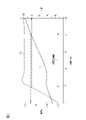
- FIG. 2 is a characteristic diagram showing the relationship between the addition rate of titanium oxide to a white resin layer and the dielectric constant and L value of the white resin layer.
- the forward direction of the vehicle is defined as the front, and the backward direction is defined as the rear.
- the left-right direction is the width direction of the vehicle and corresponds to the left-right direction when the vehicle moves forward.
- the scale of each part is appropriately changed in order to make each part of the emblem recognizable.
- a millimeter-wave radar device 12 for forward monitoring is mounted behind the front grille 11 at the central portion of the front portion of the vehicle 10 in the left-right direction.
- the front grille 11 is indicated by a two-dot chain line.
- the millimeter wave radar device 12 transmits millimeter waves, which are a form of electromagnetic waves, toward a predetermined angle range in front of the vehicle 10 outside the vehicle, and is reflected by objects outside the vehicle including preceding vehicles, pedestrians, and the like. It has a sensor function to receive millimeter waves.
- Millimeter waves refer to radio waves having a wavelength of 1 mm to 10 mm and a frequency of 30 GHz to 300 GHz.
- the millimeter-wave radar device 12 is resistant to bad weather such as rain, fog, and snow, and has a longer detectable distance than other methods.
- the direction in which the millimeter waves are transmitted by the millimeter wave radar device 12 is the direction from the rear to the front of the vehicle 10. is.
- the front in the transmission direction of the millimeter wave generally matches the front of the vehicle 10
- the rear in the same transmission direction generally matches the rear of the vehicle 10 . Therefore, in the following description, the forward direction in the transmission direction of millimeter waves is simply referred to as "front”, “front”, etc., and the rearward direction in the same transmission direction is simply referred to as "rearward”, “rear”, etc.
- the thickness of the front grille 11, in this case, the dimension in the front-rear direction, is not constant, like a general front grille.
- a metal plating layer may be formed on the surface of the base material made of resin.
- the front grille 11 interferes with transmitted or reflected millimeter waves. Therefore, in the front grille 11, a window portion 13 is opened in a portion of the millimeter wave path of the millimeter wave radar device 12, specifically, in a portion of the front grille 11 in front of the millimeter wave radar device 12. ing.
- An emblem 20 is arranged on the window portion 13 .
- the emblem 20 is arranged in an upright state so that its front surface faces the front of the vehicle 10 and its rear surface faces the rear of the vehicle 10 .
- the emblem 20 has a layered structure with a plurality of layers laminated in the front-rear direction.
- the multiple layers include a base material 21, a decorative layer 22, and a transparent resin layer 23, which are arranged in order from the rear to the front.
- the substrate 21 and the transparent resin layer 23 correspond to the resin layer in the claims.
- the base material 21 forming part of the resin layer is made of a resin material having millimeter wave transparency.
- the base material 21 is made of AES (acrylonitrile-ethylene-styrene copolymer) resin and colored such as blue or black.
- AES has a dielectric constant of about 2.7 and a dissipation factor of 0.007.
- the dielectric constant is a physical property value that indicates the degree of dielectric polarization caused by the charge of the dielectric material, in this case, the base material 21, and is the ratio of the electric flux density to the electric field strength. In general, the higher the dielectric constant, the easier it is for charges to accumulate.
- the dielectric loss tangent is an index value representing the degree of electrical energy loss within a dielectric, that is, the amount of loss due to conversion of a signal propagating within the dielectric into heat. When the dielectric loss tangent is small, it is difficult for millimeter waves to be converted into heat energy, and attenuation of millimeter waves can be suppressed.
- the base material 21 is made of a resin having a dielectric constant close to that of the transparent resin layer 23, such as ASA (acrylonitrile-styrene-acrylate copolymer) resin, PC (polycarbonate) resin, etc., instead of the AES resin. good too.
- the relative permittivity is the ratio of the permittivity of the dielectric, in this case the substrate 21, to the permittivity of the vacuum, and is a parameter that indicates the degree of polarization within the dielectric.
- the higher the dielectric constant the greater the propagation delay of millimeter waves. Therefore, in order to increase the propagation speed of millimeter waves and enable high-speed calculation of the millimeter wave radar device 12, a lower dielectric constant is preferable.
- the base material 21 may be formed of a polymer alloy of PC resin and ABS (acrylonitrile-butadiene-styrene copolymer) resin.
- the transparent resin layer 23 forming part of the resin layer is made of a resin material having millimeter wave transparency.
- the transparent resin layer 23 is arranged in front of the substrate 21 .
- the transparent resin layer 23 is transparently made of PC resin, which is a resin material with a small dielectric loss tangent.
- the PC resin has a dielectric constant of 2.7, a dielectric loss tangent of 0.006, and a relative dielectric constant substantially the same as that of the AES resin.
- the transparent resin layer 23 may be formed of PMMA (polymethyl methacrylate) resin, which is a resin material with a small dielectric loss tangent, like the PC resin.
- the decorative layer 22 is for decorating the emblem 20 and the peripheral portion of the emblem 20 in the front portion of the vehicle 10 , and is formed between the base material 21 and the transparent resin layer 23 .
- At least part of the decorative layer 22 is composed of a white resin layer 24.
- the white resin layer 24 is used to express patterns such as characters and marks.
- Such a pattern portion is generally represented by a bright decorative layer made of a metallic material.
- the pattern portion is represented by the white resin layer 24 instead of the bright decorative layer.
- the rear surface of the white resin layer 24 is in contact with the front surface of the substrate 21
- the front surface of the white resin layer 24 is in contact with the rear surface of the transparent resin layer 23 .
- the white resin layer 24 is formed by using particles of titanium oxide (TiO2) as a white pigment and incorporating this into PC resin, which is a resin material having millimeter wave transparency. That is, the white resin layer 24 is made of PC resin containing particles of titanium oxide.
- Titanium oxide has the highest refractive index among inorganic pigments. Titanium oxide has excellent covering power and hiding power, and is chemically stable. The hiding power is the ability of a pigment to cover the base by reflection, scattering and absorption of light. White pigments exhibit hiding power through reflection and scattering. For these reasons, titanium oxide is mainly used as a white pigment. Titanium oxide has no absorption in the visible light region, so it develops a whiter color.
- titanium oxide has three types of crystal structures: anatase (tetragonal), brookite (orthorhombic), and rutile (tetragonal).
- anatase type and the rutile type are industrially produced.
- Rutile-type titanium oxide is suitable for use as a pigment in paint compositions and resin compositions.
- rutile-type titanium oxide has a denser atomic arrangement than anatase-type titanium oxide and has a higher refractive index.
- titanium oxide When anatase-type titanium oxide is heated to 900°C or higher, it transitions to rutile-type. When brookite-type titanium oxide is heated to 650° C. or higher, it transitions to a rutile-type. Titanium oxide, once converted to the rutile type, maintains the rutile type even if it is returned to a low temperature. Thus, rutile-type titanium oxide is the most stable of the three crystal structures.
- the white resin layer 24 is formed of PC resin containing particles of rutile-type titanium oxide.
- the white resin layer 24 satisfies the following conditions.
- the thickness, in this case, the dimension in the front-rear direction is 2.0 mm or less.
- the dielectric constant is 3.1 or less. This value is close to the dielectric constant of PC resin (2.7) and the dielectric constant of AES resin (approximately 2.7).
- (C) L value is 80 or more in the Lab color system.
- the Lab colorimetric system is one of methods for numerically representing the color of an object.
- the L value in the Lab color system represents brightness (brightness). As the L value becomes smaller, the image becomes darker, and as the L value becomes larger, the image becomes brighter.
- the lower limit of the thickness of the white resin layer 24 is preferably 1.0 mm from the viewpoint of resin-molding the white resin layer 24 stably.
- the addition rate of titanium oxide to the white resin layer 24 is the proportion of titanium oxide when the entire volume of the white resin layer 24 made of PC resin and titanium oxide is taken as 100. As shown in FIG.
- FIG. 2 shows the results of measuring how the dielectric constant and the L value change when the addition rate is changed in the range of 0% to 10%.
- the dielectric constant is indicated by a characteristic line L1
- the L value is indicated by a characteristic line L2.
- the dielectric constant is 2.7 and the L value is about 15. .
- the dielectric constant is about 3.2 and the L value is about 100.
- the dielectric constant increases as the addition rate increases.
- the dielectric constant is approximately constant at about 2.8.
- the doping rate varies in the range of 4% to 10%, the dielectric constant increases as the doping rate increases.
- the L value increases as the addition rate increases.
- the addition rate varies in the range of 2% to 4%, the L value once increases as the addition rate increases, and then decreases to about 100.
- the addition rate varies in the range of 4% to 10%, the L value is approximately constant at about 100.
- the addition rate is set to 1.8% to 8.2% so that both the above conditions (B) and (C) are satisfied.
- the white resin layer 24 constitutes a part of the decorative layer 22
- the portion of the decorative layer 22 that is different from the white resin layer 24 has a color different from white, for example, a dark color such as black or blue.
- a dark color such as black or blue.
- the above-mentioned portion may be configured by a bright decorative layer made of a metal material such as indium (In).
- the back surface of the white resin layer 24 is in contact with the substrate 21 .
- the dielectric constant of the AES resin used to form the base material 21 is approximately 2.7.
- the dielectric constant of the white resin layer 24 is 3.1 or less as described above, which is close to the dielectric constant of the base material 21 . Therefore, when millimeter waves pass through the base material 21 and the white resin layer 24, the phenomenon of reflection and refraction at the interface between the two is suppressed, and attenuation of the millimeter waves due to reflection and refraction is suppressed.
- the transparent resin layer 23 is in contact with the front surface of the white resin layer 24 .
- the dielectric constant of the PC resin used for forming the transparent resin layer 23 is 2.7.
- the dielectric constant of the white resin layer 24 is 3.1 or less as described above, which is close to the dielectric constant of the transparent resin layer 23 . Therefore, when the millimeter waves pass through the white resin layer 24 and the transparent resin layer 23, the phenomenon of reflection and refraction at the interface between the two is suppressed, and attenuation of the millimeter waves due to reflection and refraction is suppressed. .
- titanium oxide having a rutile crystal structure is used.
- rutile-type titanium oxide has a smaller dielectric constant and dielectric loss tangent than anatase-type titanium oxide. Therefore, compared to the case where titanium oxide having an anatase-type crystal structure is used, it is possible to suppress attenuation of millimeter waves and ensure millimeter wave transmittance.
- the emblem 20 is decorated with the white resin layer 24, and the appearance of the emblem 20 and the peripheral portion of the emblem 20 in the front portion of the vehicle 10 can be improved.
- the following effects are obtained in addition to the above.
- (3-1) The reflection of the visible light by the white resin layer 24 occurs in front of the millimeter wave radar device 12 .
- the dark-colored substrate 21 such as blue or black is positioned behind the white resin layer 24 .
- the white resin layer 24 and base material 21 function to cover the millimeter wave radar device 12 . Therefore, it is difficult to see the millimeter wave radar device 12 from the front of the emblem 20 . Therefore, compared to the case where the millimeter wave radar device 12 can be seen through the emblem 20, the appearance of the front portion of the vehicle 10 is improved.
- At least a part of the decorative layer 22 may be composed of the white resin layer 24 . Therefore, the entire decorative layer 22 may be composed of the white resin layer 24 . Also, the decorative layer 22 may be configured by combining at least one of the above-described colored decorative layer and bright decorative layer with the white resin layer 24 .
- the emblem 20 has a layered structure with a plurality of layers laminated in the front-rear direction.
- the multiple layers include a decorative layer 22 .
- the structure of layers other than the decorative layer 22 in this layer structure may be different from the above-described embodiment, for example, may be changed as follows.
- the number of layers in the layer structure may be changed to 2 or 4 or more.
- At least one of the transparent resin layer 23 and the substrate 21 in the above embodiment may be omitted.
- the layer is formed of a colorless and transparent resin material so that the white resin layer 24 can be seen through the same layer from the outside of the vehicle 10. .
- the layer may be transparent or opaque.
- the millimeter-wave transparent garnish must be placed in front of the vehicle 10 in the transmission direction of millimeter waves from the millimeter-wave radar device 12, decorate the vehicle 10, and have millimeter-wave transparency. Additionally, it may be applied to a decorative part different from the emblem 20. FIG.
- the millimeter-wave radar device 12 may be a device for rear monitoring, front side monitoring, or rear side monitoring, in addition to forward monitoring.
- the millimeter wave transparent garnish is arranged in front of the millimeter wave radar device 12 in the transmission direction.
- the millimeter-wave transparent garnish can also be placed when the millimeter-wave radar device 12 is mounted on a vehicle other than a vehicle, such as a train, an aircraft, or a ship.
Landscapes
- Engineering & Computer Science (AREA)
- Radar, Positioning & Navigation (AREA)
- Remote Sensing (AREA)
- Physics & Mathematics (AREA)
- Electromagnetism (AREA)
- Computer Networks & Wireless Communication (AREA)
- General Physics & Mathematics (AREA)
- Computer Security & Cryptography (AREA)
- Radar Systems Or Details Thereof (AREA)
Abstract
ミリ波透過ガーニッシュ(20)は、ミリ波の送信方向におけるミリ波レーダ装置(12)の前方に配置される。ミリ波透過ガーニッシュ(20)は、上記送信方向に積層された複数の層を備えた層構造を有する。複数の層は、加飾層(22)と樹脂層(21、23)とを有する。加飾層(22)は、少なくとも一部が白色樹脂層(24)により構成される。樹脂層(21、23)は、白色樹脂層(24)に接触している。白色樹脂層(24)は、ルチル型の結晶構造を有する酸化チタンの粒子を含有するポリカーボネート樹脂からなる。白色樹脂層(24)は、上記送信方向の厚さが2.0mm以下であり、誘電率が3.1以下であり、Lab表色系におけるL値が80以上である。
Description
本開示は、ミリ波を送信及び受信するミリ波レーダ装置が搭載された乗物に適用され、ミリ波を透過し、かつ乗物を装飾するミリ波透過ガーニッシュに関する。
ミリ波レーダ装置が搭載された車両では、同装置からミリ波が車外へ向けて送信される。先行車両、歩行者等を含む車外の物体に当たって反射されたミリ波は、上記ミリ波レーダ装置によって受信される。そして、ミリ波レーダ装置は、送信及び受信したミリ波により上記物体を認識し、車両と物体との距離、相対速度等を検出する。
上記車両では、ミリ波の送信方向におけるミリ波レーダ装置の前方に、ミリ波透過性を有するフロントグリル、エンブレム等のミリ波透過ガーニッシュが配置される。ミリ波透過ガーニッシュは、上記送信方向に積層された複数の層を備えた層構造を有する。複数の層の1つは、加飾層によって構成される。加飾層は、例えば、金属光沢を自身の少なくとも一部に有する。そのため、車外からミリ波透過ガーニッシュを見た場合、加飾層の少なくとも一部が金属のように光り輝いて見える。加飾層によってミリ波透過ガーニッシュが装飾され、車両においてミリ波透過ガーニッシュの周辺部分の外観が向上する。
ところで、近年では、ミリ波の透過性を確保しつつ加飾層における上記金属光沢を白く発色させたいといった要望がなされることがある。
そこで、例えば、特許文献1には、鱗片状ガラス基体にルチル型二酸化チタンが被覆された白色顔料が、比較例2,3の顔料7として記載されている。この顔料7が、加飾層を構成する光輝性被膜に含有される。
そこで、例えば、特許文献1には、鱗片状ガラス基体にルチル型二酸化チタンが被覆された白色顔料が、比較例2,3の顔料7として記載されている。この顔料7が、加飾層を構成する光輝性被膜に含有される。
また、特許文献2には、フレーク状ガラス上に、ルチル型酸化チタンからなる酸化チタン層と銀層とを順に積層した光輝性顔料が記載されている。この光輝性顔料が含有された組成物を用いて上記加飾層を形成すると、その加飾層を白く発色させることが可能である。
ところが、上記特許文献1及び特許文献2に記載された技術は、加飾層における金属光沢を白く発色させるためのものである。そのため、これらの技術は、加飾層の少なくとも一部が白色樹脂層によって構成されているミリ波透過ガーニッシュにおいて、その白色樹脂層を白く発色させたい場合には、適していない。
こうした問題は、上記ミリ波透過ガーニッシュが車両とは異なる乗物に取付けられた場合にも、同様に起こり得る。
上記課題を解決するミリ波透過ガーニッシュは、ミリ波を送信及び受信するミリ波レーダ装置が搭載された乗物に適用され、前記ミリ波の送信方向における前記ミリ波レーダ装置の前方に配置されるように構成されたミリ波透過ガーニッシュであって、前記送信方向に積層された複数の層を備えた層構造を有するミリ波透過ガーニッシュにおいて、前記複数の層は、前記乗物を装飾するように構成された加飾層と樹脂層とを有し、前記加飾層は、少なくとも一部が白色樹脂層により構成され、前記樹脂層は、前記白色樹脂層に接触しており、前記白色樹脂層は、ルチル型の結晶構造を有する酸化チタンの粒子を含有するポリカーボネート樹脂からなり、前記白色樹脂層は、前記送信方向の厚さが2.0mm以下であり、誘電率が3.1以下であり、Lab表色系におけるL値が80以上である。
以下、ミリ波透過ガーニッシュを車両用のエンブレムに具体化した一実施形態について、図面を参照して説明する。
なお、以下の記載に関し、車両の前進方向を前方とし、後進方向を後方として説明する。また、左右方向は車幅方向であって車両の前進時の左右方向と一致するものとする。また、図1では、エンブレムにおける各部を認識可能な大きさとするために、各部の縮尺を適宜変更して図示している。
なお、以下の記載に関し、車両の前進方向を前方とし、後進方向を後方として説明する。また、左右方向は車幅方向であって車両の前進時の左右方向と一致するものとする。また、図1では、エンブレムにおける各部を認識可能な大きさとするために、各部の縮尺を適宜変更して図示している。
図1に示すように、車両10の前部の左右方向における中央部分であって、フロントグリル11の後方には、前方監視用のミリ波レーダ装置12が搭載されている。図1において、フロントグリル11は二点鎖線で示されている。ミリ波レーダ装置12は、電磁波の一形態であるミリ波を車外のうち、車両10の前方における所定の角度範囲へ向けて送信し、先行車両、歩行者等を含む車外の物体に当たって反射されたミリ波を受信するセンサ機能を有する。ミリ波とは、波長が1mm~10mmであり、かつ周波数が30GHz~300GHzである電波をいう。ミリ波レーダ装置12は、雨や霧、雪といった悪天候に強く、他の方式と比較して検出可能距離が長いといった特徴を有している。
なお、上述したように、ミリ波レーダ装置12が車両10の前方に向けてミリ波を送信することから、ミリ波レーダ装置12によるミリ波の送信方向は、車両10の後方から前方へ向かう方向である。ミリ波の送信方向における前方は、車両10の前方と概ね合致し、同送信方向における後方は車両10の後方と概ね合致する。そのため、以後の記載では、ミリ波の送信方向における前方を単に「前方」、「前」等といい、同送信方向における後方を単に「後方」、「後」等というものとする。
上記フロントグリル11の厚さ、この場合、前後方向の寸法は、一般的なフロントグリルと同様、一定ではない。また、フロントグリル11では、樹脂製基材の表面に金属めっき層が形成されることがある。この場合、フロントグリル11は、送信又は反射されたミリ波と干渉する。そこで、フロントグリル11において、ミリ波レーダ装置12のミリ波の経路となる箇所、具体的には、フロントグリル11において、ミリ波レーダ装置12の前方となる箇所には、窓部13が開口されている。
窓部13には、エンブレム20が配置されている。エンブレム20は、その前面が車両10の前方を向き、かつ後面が車両10の後方を向くように、起立した状態で配置される。
エンブレム20は、前後方向に積層された複数の層を備えた層構造を有している。複数の層は、後方から前方に向けて順に配置された基材21、加飾層22及び透明樹脂層23を備えている。これらの層のうち、基材21及び透明樹脂層23は、請求の範囲における樹脂層に該当する。
<基材21>
上記樹脂層の一部を構成する基材21は、ミリ波透過性を有する樹脂材料によって形成されている。本実施形態では、基材21は、AES(アクリロニトリル-エチレン-スチレン共重合)樹脂によって、青色、黒色等の有色に形成されている。AESの誘電率は約2.7であり、誘電正接は0.007である。
上記樹脂層の一部を構成する基材21は、ミリ波透過性を有する樹脂材料によって形成されている。本実施形態では、基材21は、AES(アクリロニトリル-エチレン-スチレン共重合)樹脂によって、青色、黒色等の有色に形成されている。AESの誘電率は約2.7であり、誘電正接は0.007である。
誘電率とは、誘電体、この場合、基材21が有する電荷に対して誘電分極が引き起こされる性質の度合いを示す物性値であり、電束密度と電界の強さとの比である。一般に、誘電率が大きいほど、電荷が溜まりやすい。誘電正接は、誘電体内での電気エネルギ損失の度合い、すなわち、誘電体内を伝搬する信号が熱に変換されて失われる量を表す指標値である。誘電正接が小さいと、ミリ波が熱エネルギに変換され難く、ミリ波の減衰を抑制することが可能である。
なお、基材21は、AES樹脂に代えて、透明樹脂層23に対し比誘電率が近い樹脂、例えば、ASA(アクリロニトリル-スチレン-アクリレート共重合)樹脂、PC(ポリカーボネート)樹脂等によって形成されてもよい。比誘電率とは、誘電体、この場合、基材21の誘電率と真空の誘電率との比であり、誘電体内の分極の程度を示すパラメータである。比誘電率が高い程、ミリ波の伝搬遅延が大きくなる。従って、ミリ波の伝搬速度を高め、ミリ波レーダ装置12の高速演算を可能にするためには、比誘電率は低いほうが好ましい。
また、基材21は、PC樹脂とABS(アクリロニトリル-ブタジエン-スチレン共重合)樹脂とのポリマーアロイによって形成されてもよい。
<透明樹脂層23>
上記樹脂層の一部を構成する透明樹脂層23は、ミリ波透過性を有する樹脂材料によって形成されている。透明樹脂層23は、上記基材21の前方に配置されている。透明樹脂層23は、誘電正接の小さな樹脂材料であるPC樹脂により透明に形成されている。PC樹脂の誘電率は、2.7であり、誘電正接は、0.006であり、比誘電率はAES樹脂の比誘電率とほぼ同じである。なお、透明樹脂層23は、上記PC樹脂と同様に、誘電正接の小さな樹脂材料であるPMMA(ポリメタクリル酸メチル)樹脂によって形成されてもよい。
<透明樹脂層23>
上記樹脂層の一部を構成する透明樹脂層23は、ミリ波透過性を有する樹脂材料によって形成されている。透明樹脂層23は、上記基材21の前方に配置されている。透明樹脂層23は、誘電正接の小さな樹脂材料であるPC樹脂により透明に形成されている。PC樹脂の誘電率は、2.7であり、誘電正接は、0.006であり、比誘電率はAES樹脂の比誘電率とほぼ同じである。なお、透明樹脂層23は、上記PC樹脂と同様に、誘電正接の小さな樹脂材料であるPMMA(ポリメタクリル酸メチル)樹脂によって形成されてもよい。
<加飾層22>
加飾層22は、エンブレム20と、車両10の前部のうちエンブレム20の周辺部分とを装飾するためのものであり、基材21と透明樹脂層23との間に形成されている。
加飾層22は、エンブレム20と、車両10の前部のうちエンブレム20の周辺部分とを装飾するためのものであり、基材21と透明樹脂層23との間に形成されている。
加飾層22の少なくとも一部は、白色樹脂層24によって構成されている。白色樹脂層24は、本実施形態では、文字、マーク等の模様部分の表現に用いられている。こうした模様部分の表現は、一般には、金属材料からなる光輝加飾層によってなされている。本実施形態では、エンブレム20の意匠性の観点から、光輝加飾層に代えて白色樹脂層24によって模様部分が表現されている。白色樹脂層24の後面は基材21の前面に接触し、同白色樹脂層24の前面は透明樹脂層23の後面に接触している。
白色樹脂層24は、酸化チタン(TiO2 )の粒子を白色顔料として用い、これを、ミリ波透過性を有する樹脂材料であるPC樹脂に含有させることによって形成されている。すなわち、白色樹脂層24は、酸化チタンの粒子を含有するPC樹脂からなる。
酸化チタンは、無機顔料の中では最も高い屈折率を有する。酸化チタンは、被覆力及び隠蔽力に優れ、さらに化学的にも安定である。隠蔽力とは、顔料が有する、光の反射と散乱、吸収によって下地を覆い隠す力のことである。白色顔料の場合には、反射及び散乱により隠蔽力を示す。これらのことから、酸化チタンは白色顔料を主な用途とされる。酸化チタンは、可視光領域に吸収がないことから、より白く発色する。
ここで、酸化チタンは、アナターゼ型(正方晶)、ブルーカイト型(斜方晶)及びルチル型(正方晶)の3種類の結晶構造を有する。これらの中で工業的に製造されているのは、アナターゼ型とルチル型である。ルチル型酸化チタンは、塗料組成物や樹脂組成物に顔料として配合する場合に適している。さらに、ルチル型酸化チタンは、アナターゼ型酸化チタンよりも緻密な原子配列をとっていて、屈折率が高い。
アナターゼ型の酸化チタンを900℃以上に加熱すると、ルチル型に転移する。また、ブルーカイト型の酸化チタンを650℃以上に加熱すると、ルチル型に転移する。酸化チタンは、一度ルチル型に転移すると、低温に戻されてもルチル型を維持する。このように、ルチル型酸化チタンは、3種類の結晶構造のうち、最も安定している。
ルチル型及びアナターゼ型のそれぞれの酸化チタンについて、誘電率及び誘電正接を測定したところ、誘電率及び誘電正接のいずれに関しても、ルチル型の方が、アナターゼ型に比べ小さいことが判った。
本実施形態では、ルチル型酸化チタンの粒子を含有させたPC樹脂によって白色樹脂層24が形成されている。
白色樹脂層24は、以下の条件を満たしている。
白色樹脂層24は、以下の条件を満たしている。
(A)厚さ、この場合、前後方向の寸法が2.0mm以下である。
(B)ミリ波レーダ装置12が、76.5GHzの周波数を中央値とする帯域でミリ波を送信する場合、誘電率が3.1以下である。この値は、PC樹脂の誘電率(2.7)及びAES樹脂の誘電率(約2.7)に近い値である。
(B)ミリ波レーダ装置12が、76.5GHzの周波数を中央値とする帯域でミリ波を送信する場合、誘電率が3.1以下である。この値は、PC樹脂の誘電率(2.7)及びAES樹脂の誘電率(約2.7)に近い値である。
(C)Lab表色系におけるL値が80以上である。
Lab表色系は、物体の色を数値で表すための方式の1つである。Lab表色系におけるL値は明るさ(明度)を表している。L値が小さくなるに従い暗くなり、L値が大きくなるに従い明るくなる。
Lab表色系は、物体の色を数値で表すための方式の1つである。Lab表色系におけるL値は明るさ(明度)を表している。L値が小さくなるに従い暗くなり、L値が大きくなるに従い明るくなる。
なお、白色樹脂層24の厚さの下限値は、安定して同白色樹脂層24を樹脂成形する観点からは、1.0mmであることが好ましい。
ここで、白色樹脂層24の誘電率及びL値の両者に関連する要素として、白色樹脂層24に対する酸化チタンの添加率がある。添加率は、PC樹脂と酸化チタンとからなる白色樹脂層24の全体の体積を100とした場合、酸化チタンが占める割合である。
ここで、白色樹脂層24の誘電率及びL値の両者に関連する要素として、白色樹脂層24に対する酸化チタンの添加率がある。添加率は、PC樹脂と酸化チタンとからなる白色樹脂層24の全体の体積を100とした場合、酸化チタンが占める割合である。
図2は、添加率を0%~10%の範囲で変化させた場合に、誘電率及びL値がそれぞれどのように変化するのかを測定した結果を示している。図2中、誘電率は特性線L1で示され、L値は特性線L2で示されている。
添加率が0%、すなわち、酸化チタンが添加されておらず、白色樹脂層24がPC樹脂のみによって形成されている場合には、誘電率が2.7であり、L値が15程度である。これに対し、添加率が10%の場合には、誘電率が3.2程度であり、L値が100程度である。
添加率が0%~2%の範囲で変化する場合には、添加率の増加に伴い誘電率が増加する。添加率が2%~4%の範囲で変化する場合には、誘電率は2.8程度で略一定となる。添加率が4%~10%の範囲で変化する場合には、添加率の増加に伴い誘電率が増加する。
また、添加率が0%~2%の範囲で変化する場合には、添加率の増加に伴いL値が増加する。添加率が2%~4%の範囲で変化する場合には、添加率の増加に伴いL値が一旦増加した後に減少して100程度になる。添加率が4%~10%の範囲で変化する場合には、L値は100程度で略一定となる。
上記図2から、次のことが判る。
・添加率が0%~8.2%の範囲では、誘電率が3.1以下となり、上記(B)の条件が満たされる。
・添加率が0%~8.2%の範囲では、誘電率が3.1以下となり、上記(B)の条件が満たされる。
・添加率が1.8%~10%の範囲では、L値が80以上となり、上記(C)の条件が満たされる。
・上記0%~8.2%の範囲と、上記1.8%~10%の範囲とが重複する範囲を「2特性適合範囲」というものとすると、この「2特性適合範囲」では、誘電率が3.1以下になり、かつL値が80以上になる。
・上記0%~8.2%の範囲と、上記1.8%~10%の範囲とが重複する範囲を「2特性適合範囲」というものとすると、この「2特性適合範囲」では、誘電率が3.1以下になり、かつL値が80以上になる。
そこで、本実施形態では、添加率が、1.8%~8.2%に設定されることにより、上記(B),(C)の条件がともに満たされるようにしている。
上記白色樹脂層24が加飾層22の一部を構成する場合、同加飾層22のうち白色樹脂層24とは異なる箇所は、白色とは異なる色、例えば、黒色、青色等の濃色を有する有色加飾層によって構成されてもよい。また、上記箇所は、インジウム(In)等の金属材料からなる光輝加飾層によって構成されてもよい。
上記白色樹脂層24が加飾層22の一部を構成する場合、同加飾層22のうち白色樹脂層24とは異なる箇所は、白色とは異なる色、例えば、黒色、青色等の濃色を有する有色加飾層によって構成されてもよい。また、上記箇所は、インジウム(In)等の金属材料からなる光輝加飾層によって構成されてもよい。
次に、上記のように構成された本実施形態の作用について説明する。また、作用に伴い生ずる効果についても併せて説明する。
<白色樹脂層24のミリ波透過性について>
図1において、ミリ波レーダ装置12からミリ波が送信されると、そのミリ波は、エンブレム20の各層、すなわち基材21、加飾層22及び透明樹脂層23を順に透過する。エンブレム20を透過したミリ波は、先行車両、歩行者等を含む車両前方の物体に当たって反射された後、再びエンブレム20の各層を上記とは逆の順に透過し、ミリ波レーダ装置12によって受信される。ミリ波レーダ装置12では、送信及び受信された上記ミリ波に基づき、物体が認識され、車両10と同物体との距離、相対速度等の検出等が行われる。
<白色樹脂層24のミリ波透過性について>
図1において、ミリ波レーダ装置12からミリ波が送信されると、そのミリ波は、エンブレム20の各層、すなわち基材21、加飾層22及び透明樹脂層23を順に透過する。エンブレム20を透過したミリ波は、先行車両、歩行者等を含む車両前方の物体に当たって反射された後、再びエンブレム20の各層を上記とは逆の順に透過し、ミリ波レーダ装置12によって受信される。ミリ波レーダ装置12では、送信及び受信された上記ミリ波に基づき、物体が認識され、車両10と同物体との距離、相対速度等の検出等が行われる。
(1-1)ここで、図2を用いて上述したように、白色樹脂層24に対する酸化チタンの添加率と、同白色樹脂層24の誘電率との間には一定の関係が見られる。添加率が8.2%以下の範囲では誘電率が3.1以下になる。この点、本実施形態では、添加率が1.8%~8.2%に設定されている。そのため、白色樹脂層24の誘電率が3.1以下となり、必要なミリ波透過性を得ることができる。
すなわち、図1に示すように、白色樹脂層24の後面には基材21が接触している。基材21の形成に用いられるAES樹脂の誘電率は約2.7である。これに対し、白色樹脂層24の誘電率は上述したように3.1以下であり、基材21の誘電率に近い。そのため、ミリ波が基材21及び白色樹脂層24を透過する際に、両者の界面で反射したり屈折したりする現象が抑制され、反射及び屈折に起因するミリ波の減衰が抑制される。
また、白色樹脂層24の前面には透明樹脂層23が接触している。透明樹脂層23の形成に用いられるPC樹脂の誘電率は2.7である。これに対し、白色樹脂層24の誘電率は上述したように3.1以下であり、透明樹脂層23の誘電率に近い。そのため、ミリ波が白色樹脂層24及び透明樹脂層23を透過する際に、両者の界面で反射したり屈折したりする現象が抑制され、反射及び屈折に起因するミリ波の減衰が抑制される。
(1-2)さらに、本実施形態では酸化チタンとして、ルチル型の結晶構造を有するものが用いられている。上述したように、ルチル型酸化チタンは、アナターゼ型酸化チタンに比べ誘電率及び誘電正接がともに小さい。そのため、酸化チタンとして、アナターゼ型の結晶構造を有するものが用いられる場合に比べ、ミリ波の減衰を抑制してミリ波透過性を確保することができる。
(1-3)ミリ波レーダ装置12から送信されたミリ波も、車両10の外部の物体に当たって反射されたミリ波も、白色樹脂層24を透過する際に少なからず減衰される。ミリ波の減衰量と白色樹脂層24の厚さとの間には、厚さが大きくなるに従い減衰量が多くなるといった関係が見られる。本実施形態では、白色樹脂層24の厚さが2.0mm以下に設定されていることから、ミリ波の減衰量を許容範囲にとどめることができる。
上記(1-1)~(1-3)の項で説明したように、本実施形態によると、ミリ波がエンブレム20を透過する際に減衰されるのを抑制し、ミリ波減衰に起因するミリ波レーダ装置12の検出性能の低下を抑制できる。
<白色樹脂層24での白色の発色について>
一方、図1に示すように、エンブレム20に対し車両10の前方から可視光が照射されると、その可視光は、透明樹脂層23を透過し、白色樹脂層24に含有されている酸化チタンの粒子に照射される。可視光は、上記粒子によって吸収されず、又はされにくく、多くが乱反射される。そのため、車両10の前方からエンブレム20を見ると、透明樹脂層23を通して、その裏側(奥側)に白色樹脂層24が位置するように見える。
一方、図1に示すように、エンブレム20に対し車両10の前方から可視光が照射されると、その可視光は、透明樹脂層23を透過し、白色樹脂層24に含有されている酸化チタンの粒子に照射される。可視光は、上記粒子によって吸収されず、又はされにくく、多くが乱反射される。そのため、車両10の前方からエンブレム20を見ると、透明樹脂層23を通して、その裏側(奥側)に白色樹脂層24が位置するように見える。
(2-1)ここで、図2を用いて上述したように、白色樹脂層24に対する酸化チタンの添加率と、L値との間には一定の関係が見られる。添加率が1.8%以上の範囲ではL値が80以上になる。この点、本実施形態では、添加率が1.8%~8.2%に設定されている。そのため、白色樹脂層24のL値が80以上になり、同白色樹脂層24が白く発色する。透明樹脂層23を通じて白色樹脂層24が白色に見える。上述したように、白色樹脂層24によって、文字、マーク等の模様部分が表現されている本実施形態では、その模様部分が白く見える。
このように、本実施形態によると、白色樹脂層24によってエンブレム20を装飾し、同エンブレム20と、車両10の前部のうちエンブレム20の周辺部分との外観を向上できる。
本実施形態によると、上記以外にも、次の効果が得られる。
(3-1)可視光の白色樹脂層24での上記反射は、ミリ波レーダ装置12よりも前方で行われる。しかも、白色樹脂層24の後側には、青色、黒色等の濃色の基材21が位置している。これらの白色樹脂層24及び基材21は、ミリ波レーダ装置12を覆い隠す機能を発揮する。そのため、エンブレム20よりも前方からは、ミリ波レーダ装置12が見えにくい。従って、ミリ波レーダ装置12がエンブレム20を通して透けて見える場合に比べて、車両10の前部の外観が向上する。
(3-1)可視光の白色樹脂層24での上記反射は、ミリ波レーダ装置12よりも前方で行われる。しかも、白色樹脂層24の後側には、青色、黒色等の濃色の基材21が位置している。これらの白色樹脂層24及び基材21は、ミリ波レーダ装置12を覆い隠す機能を発揮する。そのため、エンブレム20よりも前方からは、ミリ波レーダ装置12が見えにくい。従って、ミリ波レーダ装置12がエンブレム20を通して透けて見える場合に比べて、車両10の前部の外観が向上する。
なお、上記実施形態は、これを以下のように変更した変形例として実施することもできる。上記実施形態及び以下の変形例は、技術的に矛盾しない範囲で互いに組み合わせて実施することができる。
<白色樹脂層24について>
・加飾層22は、少なくとも一部が白色樹脂層24によって構成されていればよい。従って、加飾層22の全部が白色樹脂層24によって構成されてもよい。また、加飾層22が、上述した有色加飾層及び光輝加飾層の少なくとも一方と白色樹脂層24との組み合わせによって構成されてもよい。
・加飾層22は、少なくとも一部が白色樹脂層24によって構成されていればよい。従って、加飾層22の全部が白色樹脂層24によって構成されてもよい。また、加飾層22が、上述した有色加飾層及び光輝加飾層の少なくとも一方と白色樹脂層24との組み合わせによって構成されてもよい。
<エンブレム20の層構造について>
エンブレム20は、前後方向に積層された複数の層を備えた層構造を有する。複数の層は、加飾層22を含む。この層構造における加飾層22以外の層の構成が、上記実施形態とは異なる構成、例えば、下記のように変更されてもよい。
エンブレム20は、前後方向に積層された複数の層を備えた層構造を有する。複数の層は、加飾層22を含む。この層構造における加飾層22以外の層の構成が、上記実施形態とは異なる構成、例えば、下記のように変更されてもよい。
・層構造における層の数が、2又は4以上に変更されてもよい。
・上記実施形態における透明樹脂層23及び基材21の少なくとも一方が省略されてもよい。
・上記実施形態における透明樹脂層23及び基材21の少なくとも一方が省略されてもよい。
・加飾層22よりも前側に層が設けられる場合、その層は、車両10の外部から同層を通して白色樹脂層24が透けて見えるようにするために、無色透明な樹脂材料によって形成される。
・加飾層22よりも後側に層が設けられる場合、その層は、透明であってもよいし不透明であってもよい。
<その他>
・ミリ波透過ガーニッシュは、車両10において、ミリ波レーダ装置12からのミリ波の送信方向の前方に配置されて、同車両10を装飾するとともに、ミリ波透過性を有するものであることを条件に、エンブレム20とは異なる装飾部品に適用されてもよい。
<その他>
・ミリ波透過ガーニッシュは、車両10において、ミリ波レーダ装置12からのミリ波の送信方向の前方に配置されて、同車両10を装飾するとともに、ミリ波透過性を有するものであることを条件に、エンブレム20とは異なる装飾部品に適用されてもよい。
・ミリ波レーダ装置12は、前方監視用以外にも、後方監視用、前側方監視用、又は後側方監視用の装置であってもよい。この場合、ミリ波透過ガーニッシュは、上記送信方向におけるミリ波レーダ装置12の前方に配置される。
・ミリ波透過ガーニッシュは、ミリ波レーダ装置12が、車両とは異なる種類の乗物、例えば、電車、航空機、船舶等の乗物に搭載された場合にも配置可能である。
Claims (4)
- ミリ波を送信及び受信するミリ波レーダ装置が搭載された乗物に適用され、前記ミリ波の送信方向における前記ミリ波レーダ装置の前方に配置されるように構成されたミリ波透過ガーニッシュであって、前記送信方向に積層された複数の層を備えた層構造を有するミリ波透過ガーニッシュにおいて、
前記複数の層は、前記乗物を装飾するように構成された加飾層と樹脂層とを有し、
前記加飾層は、少なくとも一部が白色樹脂層により構成され、
前記樹脂層は、前記白色樹脂層に接触しており、
前記白色樹脂層は、ルチル型の結晶構造を有する酸化チタンの粒子を含有するポリカーボネート樹脂からなり、
前記白色樹脂層は、前記送信方向の厚さが2.0mm以下であり、誘電率が3.1以下であり、Lab表色系におけるL値が80以上であるミリ波透過ガーニッシュ。 - 前記酸化チタンは、前記白色樹脂層に対し、1.8%~8.2%の添加率で添加されている請求項1に記載のミリ波透過ガーニッシュ。
- 前記樹脂層は、ポリカーボネート樹脂からなる透明樹脂層を備えており、
前記透明樹脂層は、前記送信方向における前記白色樹脂層の前面に接触している請求項1又は2に記載のミリ波透過ガーニッシュ。 - 前記樹脂層は、アクリロニトリル-エチレン-スチレン共重合樹脂からなる基材を備えており、
前記基材は、前記送信方向における前記白色樹脂層の後面に接触している請求項1~3のいずれか1項に記載のミリ波透過ガーニッシュ。
Priority Applications (1)
| Application Number | Priority Date | Filing Date | Title |
|---|---|---|---|
| US18/556,806 US20240201366A1 (en) | 2021-05-31 | 2022-05-18 | Millimeter-wave-transmitting garnish |
Applications Claiming Priority (2)
| Application Number | Priority Date | Filing Date | Title |
|---|---|---|---|
| JP2021-090929 | 2021-05-31 | ||
| JP2021090929A JP7494796B2 (ja) | 2021-05-31 | 2021-05-31 | ミリ波透過ガーニッシュ |
Publications (1)
| Publication Number | Publication Date |
|---|---|
| WO2022255106A1 true WO2022255106A1 (ja) | 2022-12-08 |
Family
ID=84323194
Family Applications (1)
| Application Number | Title | Priority Date | Filing Date |
|---|---|---|---|
| PCT/JP2022/020739 Ceased WO2022255106A1 (ja) | 2021-05-31 | 2022-05-18 | ミリ波透過ガーニッシュ |
Country Status (3)
| Country | Link |
|---|---|
| US (1) | US20240201366A1 (ja) |
| JP (1) | JP7494796B2 (ja) |
| WO (1) | WO2022255106A1 (ja) |
Families Citing this family (3)
| Publication number | Priority date | Publication date | Assignee | Title |
|---|---|---|---|---|
| EP4270046A4 (en) * | 2021-07-21 | 2024-12-11 | Nitto Denko Corporation | SHIELDING AGAINST ELECTROMAGNETIC WAVES |
| EP4270654A4 (en) * | 2021-08-06 | 2024-12-04 | Nitto Denko Corporation | SHIELDING AND ELECTROMAGNETIC WAVE ASSEMBLY |
| JP7810136B2 (ja) * | 2023-03-24 | 2026-02-03 | 豊田合成株式会社 | 積層体 |
Citations (8)
| Publication number | Priority date | Publication date | Assignee | Title |
|---|---|---|---|---|
| JP2004312696A (ja) * | 2003-03-24 | 2004-11-04 | Hitachi Ltd | ミリ波レーダおよびその製造方法 |
| WO2006041093A1 (ja) * | 2004-10-12 | 2006-04-20 | Nagoya Industrial Science Research Institute | 高周波用誘電体セラミックス |
| JP2006267019A (ja) * | 2005-03-25 | 2006-10-05 | Toyota Motor Corp | レーダ装置ビーム経路内用光輝装飾成形品 |
| JP2009091411A (ja) * | 2007-10-04 | 2009-04-30 | Nippon Sheet Glass Co Ltd | 光輝性顔料含有組成物、印刷物、および塗装物 |
| JP2009102626A (ja) * | 2007-10-05 | 2009-05-14 | Nippon Sheet Glass Co Ltd | 車両用電磁波透過性塗装樹脂部品 |
| WO2017104714A1 (ja) * | 2015-12-16 | 2017-06-22 | テクノポリマー株式会社 | レーダー装置が発するビームの経路に配置される樹脂部品、レドーム及びレーダー装置 |
| CN111200185A (zh) * | 2018-10-31 | 2020-05-26 | 航天特种材料及工艺技术研究所 | 测控用天线罩、天线/天线罩一体化结构及其制造方法 |
| JP2021028621A (ja) * | 2019-08-13 | 2021-02-25 | 豊田合成株式会社 | 車載センサカバー |
Family Cites Families (6)
| Publication number | Priority date | Publication date | Assignee | Title |
|---|---|---|---|---|
| JP5275856B2 (ja) * | 2009-03-16 | 2013-08-28 | 株式会社東海理化電機製作所 | 装飾部材、レーダユニット、装飾部材製造方法 |
| EP2740597B1 (de) * | 2012-12-10 | 2015-11-04 | Mitsubishi Polyester Film GmbH | Weiße, biaxial orientierte, mindestens einseitig matte und bewitterungsstabile Polyesterfolie, Verfahren zu ihrer Herstellung und ihre Verwendung |
| KR102156556B1 (ko) * | 2016-07-15 | 2020-09-16 | 후지필름 가부시키가이샤 | 적층체, 키트, 적층체의 제조 방법 및 광학 센서 |
| EP4005022B1 (en) * | 2019-07-29 | 2025-09-17 | Motherson Innovations Company Limited | First surface or second surface decorative radome |
| EP4186950A1 (de) * | 2021-11-26 | 2023-05-31 | Schlenk Metallic Pigments GmbH | Verwendung einer metalleffektpigmente enthaltenden lackformulierung zum lackieren eines mit einem radarsensor und einem lidarsensor ausgestatteten fahrzeugs |
| FR3136063B1 (fr) * | 2022-04-12 | 2024-05-03 | Valeo Vision | Ensemble de véhicule comprenant un capteur radar et un agencement de couches |
-
2021
- 2021-05-31 JP JP2021090929A patent/JP7494796B2/ja active Active
-
2022
- 2022-05-18 WO PCT/JP2022/020739 patent/WO2022255106A1/ja not_active Ceased
- 2022-05-18 US US18/556,806 patent/US20240201366A1/en active Pending
Patent Citations (8)
| Publication number | Priority date | Publication date | Assignee | Title |
|---|---|---|---|---|
| JP2004312696A (ja) * | 2003-03-24 | 2004-11-04 | Hitachi Ltd | ミリ波レーダおよびその製造方法 |
| WO2006041093A1 (ja) * | 2004-10-12 | 2006-04-20 | Nagoya Industrial Science Research Institute | 高周波用誘電体セラミックス |
| JP2006267019A (ja) * | 2005-03-25 | 2006-10-05 | Toyota Motor Corp | レーダ装置ビーム経路内用光輝装飾成形品 |
| JP2009091411A (ja) * | 2007-10-04 | 2009-04-30 | Nippon Sheet Glass Co Ltd | 光輝性顔料含有組成物、印刷物、および塗装物 |
| JP2009102626A (ja) * | 2007-10-05 | 2009-05-14 | Nippon Sheet Glass Co Ltd | 車両用電磁波透過性塗装樹脂部品 |
| WO2017104714A1 (ja) * | 2015-12-16 | 2017-06-22 | テクノポリマー株式会社 | レーダー装置が発するビームの経路に配置される樹脂部品、レドーム及びレーダー装置 |
| CN111200185A (zh) * | 2018-10-31 | 2020-05-26 | 航天特种材料及工艺技术研究所 | 测控用天线罩、天线/天线罩一体化结构及其制造方法 |
| JP2021028621A (ja) * | 2019-08-13 | 2021-02-25 | 豊田合成株式会社 | 車載センサカバー |
Also Published As
| Publication number | Publication date |
|---|---|
| US20240201366A1 (en) | 2024-06-20 |
| JP7494796B2 (ja) | 2024-06-04 |
| JP2022183556A (ja) | 2022-12-13 |
Similar Documents
| Publication | Publication Date | Title |
|---|---|---|
| WO2022255106A1 (ja) | ミリ波透過ガーニッシュ | |
| US10794757B2 (en) | Near-infrared sensor cover | |
| EP1837920B1 (en) | Infrared-transmitting cover | |
| JP3389360B2 (ja) | 光干渉材及びそれを含有する塗料 | |
| US10107894B2 (en) | Radio-wave-penetrable layer having metallic luster | |
| JP3720039B2 (ja) | 距離警告レーダーのレードームを製作する方法 | |
| JP2020067291A (ja) | 車載センサカバー | |
| JP3365760B2 (ja) | 発色構造体 | |
| CN109715299B (zh) | 叠层涂膜及涂装物 | |
| KR101406638B1 (ko) | 차량용 레이더 투과 커버 | |
| JP2018031888A (ja) | 近赤外線センサ用カバー | |
| CN109789438B (zh) | 叠层涂膜及涂装物 | |
| CN109789439B (zh) | 叠层涂膜及涂装物 | |
| CN115123105A (zh) | 车辆用外装品 | |
| JP7131506B2 (ja) | 車載センサカバー | |
| CN213043058U (zh) | 具有装饰图案的机动车雷达罩 | |
| JP7242261B2 (ja) | 赤外線透過カバー | |
| CN213091919U (zh) | 镀膜防护罩 | |
| JP7276406B2 (ja) | 近赤外線センサカバー | |
| JP2022129146A (ja) | 電磁波センサカバー | |
| JP7722418B2 (ja) | 車両用外装品 | |
| JP2024129491A (ja) | 光輝塗膜及びカバー | |
| JP2019188809A (ja) | 電磁波透過性金属光沢物品 | |
| JP2019117260A (ja) | 樹脂成形体、それを用いた透過カバー、ラジエータグリルおよびドアモール | |
| JP2019219690A (ja) | 近赤外線センサ用カバー |
Legal Events
| Date | Code | Title | Description |
|---|---|---|---|
| 121 | Ep: the epo has been informed by wipo that ep was designated in this application |
Ref document number: 22815858 Country of ref document: EP Kind code of ref document: A1 |
|
| WWE | Wipo information: entry into national phase |
Ref document number: 18556806 Country of ref document: US |
|
| NENP | Non-entry into the national phase |
Ref country code: DE |
|
| 122 | Ep: pct application non-entry in european phase |
Ref document number: 22815858 Country of ref document: EP Kind code of ref document: A1 |