WO2022250077A1 - 焼結体及びその製造方法、並びに歯列矯正ブラケット - Google Patents
焼結体及びその製造方法、並びに歯列矯正ブラケット Download PDFInfo
- Publication number
- WO2022250077A1 WO2022250077A1 PCT/JP2022/021371 JP2022021371W WO2022250077A1 WO 2022250077 A1 WO2022250077 A1 WO 2022250077A1 JP 2022021371 W JP2022021371 W JP 2022021371W WO 2022250077 A1 WO2022250077 A1 WO 2022250077A1
- Authority
- WO
- WIPO (PCT)
- Prior art keywords
- sintered body
- less
- mol
- lanthanum
- zirconia
- Prior art date
- Legal status (The legal status is an assumption and is not a legal conclusion. Google has not performed a legal analysis and makes no representation as to the accuracy of the status listed.)
- Ceased
Links
Images



Classifications
-
- A—HUMAN NECESSITIES
- A61—MEDICAL OR VETERINARY SCIENCE; HYGIENE
- A61C—DENTISTRY; APPARATUS OR METHODS FOR ORAL OR DENTAL HYGIENE
- A61C7/00—Orthodontics, i.e. obtaining or maintaining the desired position of teeth, e.g. by straightening, evening, regulating, separating, or by correcting malocclusions
- A61C7/12—Brackets; Arch wires; Combinations thereof; Accessories therefor
- A61C7/14—Brackets; Fixing brackets to teeth
-
- C—CHEMISTRY; METALLURGY
- C04—CEMENTS; CONCRETE; ARTIFICIAL STONE; CERAMICS; REFRACTORIES
- C04B—LIME, MAGNESIA; SLAG; CEMENTS; COMPOSITIONS THEREOF, e.g. MORTARS, CONCRETE OR LIKE BUILDING MATERIALS; ARTIFICIAL STONE; CERAMICS; REFRACTORIES; TREATMENT OF NATURAL STONE
- C04B35/00—Shaped ceramic products characterised by their composition; Ceramics compositions; Processing powders of inorganic compounds preparatory to the manufacturing of ceramic products
- C04B35/01—Shaped ceramic products characterised by their composition; Ceramics compositions; Processing powders of inorganic compounds preparatory to the manufacturing of ceramic products based on oxide ceramics
- C04B35/48—Shaped ceramic products characterised by their composition; Ceramics compositions; Processing powders of inorganic compounds preparatory to the manufacturing of ceramic products based on oxide ceramics based on zirconium or hafnium oxides, zirconates, zircon or hafnates
- C04B35/486—Fine ceramics
- C04B35/488—Composites
- C04B35/4885—Composites with aluminium oxide
-
- C—CHEMISTRY; METALLURGY
- C04—CEMENTS; CONCRETE; ARTIFICIAL STONE; CERAMICS; REFRACTORIES
- C04B—LIME, MAGNESIA; SLAG; CEMENTS; COMPOSITIONS THEREOF, e.g. MORTARS, CONCRETE OR LIKE BUILDING MATERIALS; ARTIFICIAL STONE; CERAMICS; REFRACTORIES; TREATMENT OF NATURAL STONE
- C04B35/00—Shaped ceramic products characterised by their composition; Ceramics compositions; Processing powders of inorganic compounds preparatory to the manufacturing of ceramic products
- C04B35/622—Forming processes; Processing powders of inorganic compounds preparatory to the manufacturing of ceramic products
- C04B35/64—Burning or sintering processes
- C04B35/645—Pressure sintering
- C04B35/6455—Hot isostatic pressing
-
- C—CHEMISTRY; METALLURGY
- C04—CEMENTS; CONCRETE; ARTIFICIAL STONE; CERAMICS; REFRACTORIES
- C04B—LIME, MAGNESIA; SLAG; CEMENTS; COMPOSITIONS THEREOF, e.g. MORTARS, CONCRETE OR LIKE BUILDING MATERIALS; ARTIFICIAL STONE; CERAMICS; REFRACTORIES; TREATMENT OF NATURAL STONE
- C04B2235/00—Aspects relating to ceramic starting mixtures or sintered ceramic products
- C04B2235/02—Composition of constituents of the starting material or of secondary phases of the final product
- C04B2235/30—Constituents and secondary phases not being of a fibrous nature
- C04B2235/32—Metal oxides, mixed metal oxides, or oxide-forming salts thereof, e.g. carbonates, nitrates, (oxy)hydroxides, chlorides
- C04B2235/3205—Alkaline earth oxides or oxide forming salts thereof, e.g. beryllium oxide
- C04B2235/3206—Magnesium oxides or oxide-forming salts thereof
-
- C—CHEMISTRY; METALLURGY
- C04—CEMENTS; CONCRETE; ARTIFICIAL STONE; CERAMICS; REFRACTORIES
- C04B—LIME, MAGNESIA; SLAG; CEMENTS; COMPOSITIONS THEREOF, e.g. MORTARS, CONCRETE OR LIKE BUILDING MATERIALS; ARTIFICIAL STONE; CERAMICS; REFRACTORIES; TREATMENT OF NATURAL STONE
- C04B2235/00—Aspects relating to ceramic starting mixtures or sintered ceramic products
- C04B2235/02—Composition of constituents of the starting material or of secondary phases of the final product
- C04B2235/30—Constituents and secondary phases not being of a fibrous nature
- C04B2235/32—Metal oxides, mixed metal oxides, or oxide-forming salts thereof, e.g. carbonates, nitrates, (oxy)hydroxides, chlorides
- C04B2235/3205—Alkaline earth oxides or oxide forming salts thereof, e.g. beryllium oxide
- C04B2235/3208—Calcium oxide or oxide-forming salts thereof, e.g. lime
-
- C—CHEMISTRY; METALLURGY
- C04—CEMENTS; CONCRETE; ARTIFICIAL STONE; CERAMICS; REFRACTORIES
- C04B—LIME, MAGNESIA; SLAG; CEMENTS; COMPOSITIONS THEREOF, e.g. MORTARS, CONCRETE OR LIKE BUILDING MATERIALS; ARTIFICIAL STONE; CERAMICS; REFRACTORIES; TREATMENT OF NATURAL STONE
- C04B2235/00—Aspects relating to ceramic starting mixtures or sintered ceramic products
- C04B2235/02—Composition of constituents of the starting material or of secondary phases of the final product
- C04B2235/30—Constituents and secondary phases not being of a fibrous nature
- C04B2235/32—Metal oxides, mixed metal oxides, or oxide-forming salts thereof, e.g. carbonates, nitrates, (oxy)hydroxides, chlorides
- C04B2235/3217—Aluminum oxide or oxide forming salts thereof, e.g. bauxite, alpha-alumina
-
- C—CHEMISTRY; METALLURGY
- C04—CEMENTS; CONCRETE; ARTIFICIAL STONE; CERAMICS; REFRACTORIES
- C04B—LIME, MAGNESIA; SLAG; CEMENTS; COMPOSITIONS THEREOF, e.g. MORTARS, CONCRETE OR LIKE BUILDING MATERIALS; ARTIFICIAL STONE; CERAMICS; REFRACTORIES; TREATMENT OF NATURAL STONE
- C04B2235/00—Aspects relating to ceramic starting mixtures or sintered ceramic products
- C04B2235/02—Composition of constituents of the starting material or of secondary phases of the final product
- C04B2235/30—Constituents and secondary phases not being of a fibrous nature
- C04B2235/32—Metal oxides, mixed metal oxides, or oxide-forming salts thereof, e.g. carbonates, nitrates, (oxy)hydroxides, chlorides
- C04B2235/3224—Rare earth oxide or oxide forming salts thereof, e.g. scandium oxide
- C04B2235/3225—Yttrium oxide or oxide-forming salts thereof
-
- C—CHEMISTRY; METALLURGY
- C04—CEMENTS; CONCRETE; ARTIFICIAL STONE; CERAMICS; REFRACTORIES
- C04B—LIME, MAGNESIA; SLAG; CEMENTS; COMPOSITIONS THEREOF, e.g. MORTARS, CONCRETE OR LIKE BUILDING MATERIALS; ARTIFICIAL STONE; CERAMICS; REFRACTORIES; TREATMENT OF NATURAL STONE
- C04B2235/00—Aspects relating to ceramic starting mixtures or sintered ceramic products
- C04B2235/02—Composition of constituents of the starting material or of secondary phases of the final product
- C04B2235/30—Constituents and secondary phases not being of a fibrous nature
- C04B2235/32—Metal oxides, mixed metal oxides, or oxide-forming salts thereof, e.g. carbonates, nitrates, (oxy)hydroxides, chlorides
- C04B2235/3224—Rare earth oxide or oxide forming salts thereof, e.g. scandium oxide
- C04B2235/3227—Lanthanum oxide or oxide-forming salts thereof
-
- C—CHEMISTRY; METALLURGY
- C04—CEMENTS; CONCRETE; ARTIFICIAL STONE; CERAMICS; REFRACTORIES
- C04B—LIME, MAGNESIA; SLAG; CEMENTS; COMPOSITIONS THEREOF, e.g. MORTARS, CONCRETE OR LIKE BUILDING MATERIALS; ARTIFICIAL STONE; CERAMICS; REFRACTORIES; TREATMENT OF NATURAL STONE
- C04B2235/00—Aspects relating to ceramic starting mixtures or sintered ceramic products
- C04B2235/02—Composition of constituents of the starting material or of secondary phases of the final product
- C04B2235/30—Constituents and secondary phases not being of a fibrous nature
- C04B2235/32—Metal oxides, mixed metal oxides, or oxide-forming salts thereof, e.g. carbonates, nitrates, (oxy)hydroxides, chlorides
- C04B2235/3224—Rare earth oxide or oxide forming salts thereof, e.g. scandium oxide
- C04B2235/3229—Cerium oxides or oxide-forming salts thereof
-
- C—CHEMISTRY; METALLURGY
- C04—CEMENTS; CONCRETE; ARTIFICIAL STONE; CERAMICS; REFRACTORIES
- C04B—LIME, MAGNESIA; SLAG; CEMENTS; COMPOSITIONS THEREOF, e.g. MORTARS, CONCRETE OR LIKE BUILDING MATERIALS; ARTIFICIAL STONE; CERAMICS; REFRACTORIES; TREATMENT OF NATURAL STONE
- C04B2235/00—Aspects relating to ceramic starting mixtures or sintered ceramic products
- C04B2235/02—Composition of constituents of the starting material or of secondary phases of the final product
- C04B2235/30—Constituents and secondary phases not being of a fibrous nature
- C04B2235/32—Metal oxides, mixed metal oxides, or oxide-forming salts thereof, e.g. carbonates, nitrates, (oxy)hydroxides, chlorides
- C04B2235/3231—Refractory metal oxides, their mixed metal oxides, or oxide-forming salts thereof
- C04B2235/3244—Zirconium oxides, zirconates, hafnium oxides, hafnates, or oxide-forming salts thereof
- C04B2235/3246—Stabilised zirconias, e.g. YSZ or cerium stabilised zirconia
-
- C—CHEMISTRY; METALLURGY
- C04—CEMENTS; CONCRETE; ARTIFICIAL STONE; CERAMICS; REFRACTORIES
- C04B—LIME, MAGNESIA; SLAG; CEMENTS; COMPOSITIONS THEREOF, e.g. MORTARS, CONCRETE OR LIKE BUILDING MATERIALS; ARTIFICIAL STONE; CERAMICS; REFRACTORIES; TREATMENT OF NATURAL STONE
- C04B2235/00—Aspects relating to ceramic starting mixtures or sintered ceramic products
- C04B2235/02—Composition of constituents of the starting material or of secondary phases of the final product
- C04B2235/50—Constituents or additives of the starting mixture chosen for their shape or used because of their shape or their physical appearance
- C04B2235/54—Particle size related information
- C04B2235/5409—Particle size related information expressed by specific surface values
-
- C—CHEMISTRY; METALLURGY
- C04—CEMENTS; CONCRETE; ARTIFICIAL STONE; CERAMICS; REFRACTORIES
- C04B—LIME, MAGNESIA; SLAG; CEMENTS; COMPOSITIONS THEREOF, e.g. MORTARS, CONCRETE OR LIKE BUILDING MATERIALS; ARTIFICIAL STONE; CERAMICS; REFRACTORIES; TREATMENT OF NATURAL STONE
- C04B2235/00—Aspects relating to ceramic starting mixtures or sintered ceramic products
- C04B2235/65—Aspects relating to heat treatments of ceramic bodies such as green ceramics or pre-sintered ceramics, e.g. burning, sintering or melting processes
- C04B2235/656—Aspects relating to heat treatments of ceramic bodies such as green ceramics or pre-sintered ceramics, e.g. burning, sintering or melting processes characterised by specific heating conditions during heat treatment
- C04B2235/6562—Heating rate
-
- C—CHEMISTRY; METALLURGY
- C04—CEMENTS; CONCRETE; ARTIFICIAL STONE; CERAMICS; REFRACTORIES
- C04B—LIME, MAGNESIA; SLAG; CEMENTS; COMPOSITIONS THEREOF, e.g. MORTARS, CONCRETE OR LIKE BUILDING MATERIALS; ARTIFICIAL STONE; CERAMICS; REFRACTORIES; TREATMENT OF NATURAL STONE
- C04B2235/00—Aspects relating to ceramic starting mixtures or sintered ceramic products
- C04B2235/65—Aspects relating to heat treatments of ceramic bodies such as green ceramics or pre-sintered ceramics, e.g. burning, sintering or melting processes
- C04B2235/656—Aspects relating to heat treatments of ceramic bodies such as green ceramics or pre-sintered ceramics, e.g. burning, sintering or melting processes characterised by specific heating conditions during heat treatment
- C04B2235/6565—Cooling rate
-
- C—CHEMISTRY; METALLURGY
- C04—CEMENTS; CONCRETE; ARTIFICIAL STONE; CERAMICS; REFRACTORIES
- C04B—LIME, MAGNESIA; SLAG; CEMENTS; COMPOSITIONS THEREOF, e.g. MORTARS, CONCRETE OR LIKE BUILDING MATERIALS; ARTIFICIAL STONE; CERAMICS; REFRACTORIES; TREATMENT OF NATURAL STONE
- C04B2235/00—Aspects relating to ceramic starting mixtures or sintered ceramic products
- C04B2235/65—Aspects relating to heat treatments of ceramic bodies such as green ceramics or pre-sintered ceramics, e.g. burning, sintering or melting processes
- C04B2235/656—Aspects relating to heat treatments of ceramic bodies such as green ceramics or pre-sintered ceramics, e.g. burning, sintering or melting processes characterised by specific heating conditions during heat treatment
- C04B2235/6567—Treatment time
-
- C—CHEMISTRY; METALLURGY
- C04—CEMENTS; CONCRETE; ARTIFICIAL STONE; CERAMICS; REFRACTORIES
- C04B—LIME, MAGNESIA; SLAG; CEMENTS; COMPOSITIONS THEREOF, e.g. MORTARS, CONCRETE OR LIKE BUILDING MATERIALS; ARTIFICIAL STONE; CERAMICS; REFRACTORIES; TREATMENT OF NATURAL STONE
- C04B2235/00—Aspects relating to ceramic starting mixtures or sintered ceramic products
- C04B2235/65—Aspects relating to heat treatments of ceramic bodies such as green ceramics or pre-sintered ceramics, e.g. burning, sintering or melting processes
- C04B2235/658—Atmosphere during thermal treatment
- C04B2235/6586—Processes characterised by the flow of gas
-
- C—CHEMISTRY; METALLURGY
- C04—CEMENTS; CONCRETE; ARTIFICIAL STONE; CERAMICS; REFRACTORIES
- C04B—LIME, MAGNESIA; SLAG; CEMENTS; COMPOSITIONS THEREOF, e.g. MORTARS, CONCRETE OR LIKE BUILDING MATERIALS; ARTIFICIAL STONE; CERAMICS; REFRACTORIES; TREATMENT OF NATURAL STONE
- C04B2235/00—Aspects relating to ceramic starting mixtures or sintered ceramic products
- C04B2235/65—Aspects relating to heat treatments of ceramic bodies such as green ceramics or pre-sintered ceramics, e.g. burning, sintering or melting processes
- C04B2235/66—Specific sintering techniques, e.g. centrifugal sintering
- C04B2235/661—Multi-step sintering
-
- C—CHEMISTRY; METALLURGY
- C04—CEMENTS; CONCRETE; ARTIFICIAL STONE; CERAMICS; REFRACTORIES
- C04B—LIME, MAGNESIA; SLAG; CEMENTS; COMPOSITIONS THEREOF, e.g. MORTARS, CONCRETE OR LIKE BUILDING MATERIALS; ARTIFICIAL STONE; CERAMICS; REFRACTORIES; TREATMENT OF NATURAL STONE
- C04B2235/00—Aspects relating to ceramic starting mixtures or sintered ceramic products
- C04B2235/70—Aspects relating to sintered or melt-casted ceramic products
- C04B2235/74—Physical characteristics
- C04B2235/76—Crystal structural characteristics, e.g. symmetry
- C04B2235/762—Cubic symmetry, e.g. beta-SiC
-
- C—CHEMISTRY; METALLURGY
- C04—CEMENTS; CONCRETE; ARTIFICIAL STONE; CERAMICS; REFRACTORIES
- C04B—LIME, MAGNESIA; SLAG; CEMENTS; COMPOSITIONS THEREOF, e.g. MORTARS, CONCRETE OR LIKE BUILDING MATERIALS; ARTIFICIAL STONE; CERAMICS; REFRACTORIES; TREATMENT OF NATURAL STONE
- C04B2235/00—Aspects relating to ceramic starting mixtures or sintered ceramic products
- C04B2235/70—Aspects relating to sintered or melt-casted ceramic products
- C04B2235/74—Physical characteristics
- C04B2235/76—Crystal structural characteristics, e.g. symmetry
- C04B2235/765—Tetragonal symmetry
-
- C—CHEMISTRY; METALLURGY
- C04—CEMENTS; CONCRETE; ARTIFICIAL STONE; CERAMICS; REFRACTORIES
- C04B—LIME, MAGNESIA; SLAG; CEMENTS; COMPOSITIONS THEREOF, e.g. MORTARS, CONCRETE OR LIKE BUILDING MATERIALS; ARTIFICIAL STONE; CERAMICS; REFRACTORIES; TREATMENT OF NATURAL STONE
- C04B2235/00—Aspects relating to ceramic starting mixtures or sintered ceramic products
- C04B2235/70—Aspects relating to sintered or melt-casted ceramic products
- C04B2235/74—Physical characteristics
- C04B2235/77—Density
-
- C—CHEMISTRY; METALLURGY
- C04—CEMENTS; CONCRETE; ARTIFICIAL STONE; CERAMICS; REFRACTORIES
- C04B—LIME, MAGNESIA; SLAG; CEMENTS; COMPOSITIONS THEREOF, e.g. MORTARS, CONCRETE OR LIKE BUILDING MATERIALS; ARTIFICIAL STONE; CERAMICS; REFRACTORIES; TREATMENT OF NATURAL STONE
- C04B2235/00—Aspects relating to ceramic starting mixtures or sintered ceramic products
- C04B2235/70—Aspects relating to sintered or melt-casted ceramic products
- C04B2235/74—Physical characteristics
- C04B2235/78—Grain sizes and shapes, product microstructures, e.g. acicular grains, equiaxed grains, platelet-structures
- C04B2235/786—Micrometer sized grains, i.e. from 1 to 100 micron
-
- C—CHEMISTRY; METALLURGY
- C04—CEMENTS; CONCRETE; ARTIFICIAL STONE; CERAMICS; REFRACTORIES
- C04B—LIME, MAGNESIA; SLAG; CEMENTS; COMPOSITIONS THEREOF, e.g. MORTARS, CONCRETE OR LIKE BUILDING MATERIALS; ARTIFICIAL STONE; CERAMICS; REFRACTORIES; TREATMENT OF NATURAL STONE
- C04B2235/00—Aspects relating to ceramic starting mixtures or sintered ceramic products
- C04B2235/70—Aspects relating to sintered or melt-casted ceramic products
- C04B2235/96—Properties of ceramic products, e.g. mechanical properties such as strength, toughness, wear resistance
- C04B2235/963—Surface properties, e.g. surface roughness
-
- C—CHEMISTRY; METALLURGY
- C04—CEMENTS; CONCRETE; ARTIFICIAL STONE; CERAMICS; REFRACTORIES
- C04B—LIME, MAGNESIA; SLAG; CEMENTS; COMPOSITIONS THEREOF, e.g. MORTARS, CONCRETE OR LIKE BUILDING MATERIALS; ARTIFICIAL STONE; CERAMICS; REFRACTORIES; TREATMENT OF NATURAL STONE
- C04B2235/00—Aspects relating to ceramic starting mixtures or sintered ceramic products
- C04B2235/70—Aspects relating to sintered or melt-casted ceramic products
- C04B2235/96—Properties of ceramic products, e.g. mechanical properties such as strength, toughness, wear resistance
- C04B2235/9646—Optical properties
- C04B2235/9653—Translucent or transparent ceramics other than alumina
Definitions
- the present disclosure relates to a sintered body, its manufacturing method, and an orthodontic bracket.
- a sintered body containing zirconia as a main component and having translucency (hereinafter also referred to as a "translucent zirconia sintered body") is superior in mechanical strength to glass and alumina. Therefore, translucent zirconia sintered bodies are being studied as materials for applications that require not only optical properties but also mechanical properties.
- Patent Document 1 discloses a translucent zirconia sintered body as a material suitable for dental materials, exterior members, and the like.
- the translucent zirconia sintered body was a zirconia sintered body containing 3 mol % yttria.
- Patent Document 2 discloses a translucent zirconia sintered body as a material suitable for dental materials, particularly orthodontic brackets.
- the translucent zirconia sintered body was a zirconia sintered body containing 8 mol % yttria.
- Patent Document 3 discloses a translucent zirconia sintered body in which a stabilizer and lanthanum are dissolved in zirconia.
- Patent Document 4 discloses a translucent zirconia sintered body in which a stabilizer and lanthanum are dissolved in zirconia, which has high mechanical strength without requiring post-sintering treatment such as polishing. It is
- the translucent zirconia sintered bodies of Patent Documents 3 and 4 have higher translucency than conventional translucent zirconia sintered bodies and translucent alumina, and have mechanical strength that can be applied to orthodontic brackets. had However, due to the recent demand for higher strength and further improvement in aesthetics of orthodontic brackets, orthodontic brackets containing translucent zirconia sintered bodies are required to have higher mechanical strength and permeability. It has been
- the present disclosure is a translucent zirconia sintered body in which lanthanum is solid-dissolved and the domain structure of crystal grains is controlled, which has excellent mechanical strength and translucency, and a method for producing the same. and/or an orthodontic bracket.
- the present inventors have studied a sintered body, its manufacturing method, and an orthodontic bracket. As a result, they found that a sintered body and an orthodontic bracket having both excellent mechanical strength and translucency can be obtained by controlling the state of the material to be sintered under specific sintering conditions. was completed.
- the present invention is as described in the claims, and the gist of the present disclosure is as follows.
- a crystal grain having a cubic domain and a tetragonal domain, a matrix of zirconia in which a stabilizing element and lanthanum are dissolved, and a content of the stabilizing element of 1 mol% or more and 6 mol% or less;
- a sintered body characterized by having a torque strength of 1.00 kgf ⁇ cm or more and a linear transmittance of 35% or more for visible light with a wavelength of 600 nm at a sample thickness of 1 mm.
- [3] The sintered body according to [1] or [2], which has a lanthanum content of 1 mol% or more and 10 mol% or less.
- [4] The sintered body according to any one of [1] to [3], wherein the stabilizing element is at least one selected from the group consisting of yttrium, scandium, calcium, magnesium and cerium.
- [5] The sintered body according to any one of [1] to [4], containing at least one of lanthanoids other than lanthanum and transition metals.
- a sintered body a method for manufacturing the same, and an orthodontic bracket, which have excellent mechanical strength and translucency.
- FIG. 10 is an enlarged view showing a case where the corner where the bottom surface of the wire slot and the side surface of the wire slot on the gingival side intersect has an arc-shaped curved surface portion (R), and is an enlarged view showing the vicinity of the corner;
- Schematic side view for explaining an example of a method for preparing a measurement sample for measuring the converted transmittance of an orthodontic bracket.
- Schematic side view for explaining an example of a method for preparing a measurement sample for measuring the converted transmittance of an orthodontic bracket.
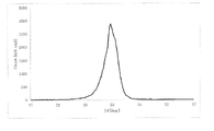
- FIG. 2 shows the XRD pattern results of Example 1.
- the sintered body of the present disclosure will be described below while showing an example of an embodiment.
- the sintered body of the present embodiment not only contains lanthanum (La) in the sintered body, but also a sintered body in which lanthanum is dissolved in zirconia (hereinafter also referred to as "lanthanum solid solution zirconia sintered body"). is.
- the solid solution of lanthanum makes the structure of the crystal grains of the sintered body finer.
- the sintered body of the present embodiment it can be confirmed from the powder X-ray diffraction (hereinafter also referred to as "XRD") pattern that lanthanum is dissolved in zirconia.
- the diffraction intensity in the pattern is the strongest XRD peak. Since the lattice parameter obtained from the main peak is larger than that of the sintered body in which lanthanum is not dissolved, it can be confirmed that lanthanum is dissolved in zirconia in the sintered body of this embodiment.
- the lattice constant of the sintered body containing only 3 mol% yttrium as a stabilizing element and the balance being zirconia is larger than the lattice constant of the crystal.
- the large lattice constant can be confirmed by the shift of the main peak to the low angle side in the XRD pattern.
- the sintered body of the present embodiment does not substantially contain composite oxides and lanthanum oxides (hereinafter also referred to as "lanthanum oxides, etc.") composed of lanthanum and zirconium.
- lanthanum oxides hereinafter also referred to as "lanthanum oxides, etc.”
- the sintered body of the present embodiment becomes a sintered body with higher translucency.
- the absence of lanthanum oxide or the like can be confirmed from the fact that the XRD pattern of the sintered body of the present embodiment does not have any XRD peaks other than those of zirconia.
- La 2 Zr 2 O 7 and La 2 O 3 can be exemplified as lanthanum oxide and the like.
- the lanthanum content of the sintered body of this embodiment is preferably 1 mol % or more. By containing 2 mol % or more of lanthanum, the domains in the crystal grains tend to be fine.
- the lanthanum content (mol%) is the molar ratio of lanthanum in terms of oxide to the total of zirconia in the sintered body, the stabilizing element in terms of oxide, and lanthanum (La 2 O 3 ) in terms of oxide.
- the lanthanum content [mol% ] is obtained as ⁇ La2O3 [ mol ]/( Y2O3 + La2O3 + ZrO2 ) [mol] ⁇ x 100. Just do it.
- the content of lanthanum in the sintered body is preferably 10 mol% or less in order to dissolve all lanthanum in zirconia.
- the lanthanum content is preferably 1 mol % or more, 2 mol % or more, or 3 mol % or more.
- it is preferably 10 mol % or less, 7 mol % or less, or 6.5 mol % or less. Any combination of these upper and lower limits may be used.
- the lanthanum content is 1 mol% or more and 10 mol% or less, further 1 mol% or more and 7 mol% or less, further 2 mol% or more and 10 mol% or less, further 2 mol% or more and 7 mol% or less, or Furthermore, it can be 2 mol % or more and 6.5 mol % or less, or further 3 mol % or more and 6.5 mol % or less.
- the sintered body of the present embodiment preferably does not contain lanthanoid-based rare earth elements other than lanthanum.
- lanthanoid rare earth elements other than lanthanum include europium (Eu), gadolinium (Gd), terbium (Tb), dysprosium (Dy), holonium (Ho), erbium (Er), thulium (Tm), and ytterbium (Yb). and lutetium (Lu).
- Eu europium
- Gd gadolinium
- Tb terbium
- Dy dysprosium
- Ho holonium
- Er erbium
- Tm thulium
- Yb ytterbium
- Lu lutetium
- the sintered body of the present embodiment does not contain lanthanoid rare earth elements other than lanthanum. It can be exemplified that it is 0.6 mol % or less.
- the sintered body of this embodiment contains a stabilizing element.
- the stabilizing element dissolves in zirconia.
- the crystal grains of the sintered body contain cubic and tetragonal domains even in a low-temperature environment such as room temperature.
- a stabilizing element is an element that has the function of stabilizing zirconia.
- the stabilizing element is, for example, preferably at least one selected from the group consisting of yttrium (Y), scandium (Sc), calcium (Ca), magnesium (Mg), and cerium (Ce). and yttrium, more preferably yttrium.
- the content of the stabilizing element contained in the sintered body of the present embodiment is 1 mol % or more and 6 mol % or less in order to partially stabilize zirconia.
- the content of the stabilizing element is preferably 1 mol % or more, or 2 mol % or more. Moreover, it is preferably 6 mol % or less, 5 mol % or less, 4.9 mol % or less, or 4 mol % or less. Any combination of these upper and lower limits may be used. Therefore, the content of the stabilizing element is preferably, for example, 2 mol % or more, and preferably 5 mol % or less, 4.9 mol % or less, or 4 mol % or less.
- the content of the stabilizing element is preferably 2 mol % or more, and is preferably 5 mol % or less, 4.9 mol % or less, or 4 mol % or less.
- the content (mol%) of the stabilizing element is the molar ratio of the stabilizing element to the total of the stabilizing element and lanthanum (La 2 O 3 ) in terms of zirconia and oxide in the sintered body. .
- the stabilizing element content [mol%] is ⁇ (Y 2 O 3 ) [mol]/(Y 2 O 3 +La 2 O 3 +ZrO 2 ) [mol] ⁇ 100. Just ask.
- the sintered body of this embodiment is a so-called zirconia sintered body, which is a sintered body containing zirconia as a matrix (main component). Therefore, the total content of the stabilizing element and lanthanum contained in the sintered body of the present embodiment may be less than 50 mol%, 20 mol% or less or 10 mol% or less, and 1 mol% or more or 2 mol% or more. It is preferable to be Any combination of these upper and lower limits may be used.
- the zirconia content of the sintered body of the present embodiment is preferably more than 50 mol%, 60 mol% or more, 80 mol% or more, 83 mol% or more, or 90 mol% or more.
- the sintered body of this embodiment may contain alumina (Al 2 O 3 ).
- alumina Al 2 O 3
- the inclusion of alumina tends to increase the translucency of a sintered body having particularly high strength.
- the alumina content is 100 mass ppm or more, or 200 mass ppm or more, and 2000 mass ppm or less, or 1000 mass ppm or less. . Any combination of these upper and lower limits may be used. Therefore, the alumina content is preferably, for example, 100 mass ppm or more and 2000 mass ppm or less, more preferably 200 mass ppm or more and 1000 mass ppm or less.
- the content of alumina is the total mass of zirconia in the sintered body, the stabilizing element converted to oxide, lanthanum (La 2 O 3 ), and aluminum (Al 2 O 3 ) converted to oxide. It is a mass ratio of aluminum (Al 2 O 3 ) in terms of oxide.
- the alumina content [mass ppm] is ⁇ Al 2 O 3 [g]/(Y 2 O 3 +La 2 O 3 +Al 2 O 3 +ZrO 2 ) [g] ⁇ 1000000.
- the sintered body of this embodiment may contain unavoidable impurities.
- inevitable impurities include hafnia (HfO 2 ).
- hafnia (HfO 2 ) which is an unavoidable impurity, is regarded as zirconia (ZrO 2 ). Just do it.
- compositions of the sintered body of the present embodiment include the following molar compositions. Zirconia: 90 mol% or more and 95 mol% or less Stabilizing element: 2 mol% or more and 5 mol% or less Lanthanum: 2 mol% or more and 6.5 mol% or less
- a particularly preferred composition of the sintered body of the present embodiment is the following molar composition. Zirconia: 92 mol% or more and 94 mol% or less Stabilizing element: 2 mol% or more and 4 mol% or less Lanthanum: 3 mol% or more and 5 mol% or less
- the stabilizing element in the above composition is preferably yttrium.
- the sintered body of this embodiment has cubic domains and tetragonal domains in crystal grains.
- a domain is at least one of a crystallite in a crystal grain or an aggregate of crystallites, and is a continuous portion of the same crystal structure.
- a cubic domain is a domain having a cubic fluorite crystal structure
- a tetragonal domain is a domain having a tetragonal fluorite crystal structure. It can be confirmed by Rietveld analysis of the XRD pattern that the sintered body of the present embodiment has cubic domains and tetragonal domains in its crystal grains.
- the sintered body of the present embodiment includes crystal grains having cubic and tetragonal domains, and is preferably made of crystal grains having cubic and tetragonal domains.
- the sintered body of the present embodiment has at least crystal grains including domains composed of crystallites having different crystal structures. Therefore, the sintered body of the present embodiment is different from a sintered body composed of crystal grains having a crystal structure of cubic zirconia only and crystal grains having a crystal structure of tetragonal zirconia only.
- the sintered body of the present embodiment includes the domains described above, its crystal structure includes a cubic fluorite structure and a tetragonal fluorite structure. Furthermore, it is preferable that the sintered body of the present embodiment does not substantially contain monoclinic crystals.
- substantially free of monoclinic crystals means that an XRD peak of monoclinic crystals is not confirmed in the XRD pattern.
- the cubic domain and the tetragonal domain may have the same lanthanum concentration.
- the cubic domain may have a higher lanthanum concentration than the tetragonal domain.
- the lanthanum concentration in each domain can be observed by composition analysis in observation with a transmission electron microscope (hereinafter also referred to as "TEM").
- the sintered body of the present embodiment has an average crystallite size calculated from the half width (hereinafter also referred to as "FWHM") of the main peak (hereinafter simply referred to as "average crystallite size”). is preferably 255 nm or less.
- the average crystallite diameter is calculated without distinguishing between cubic crystallites and tetragonal crystallites.
- the average crystallite size is 250 nm or less, further 200 nm or less, further 150 nm or less, or further 130 nm or less, the translucency tends to be high.
- the average crystallite size is 100 nm or less, further 60 nm or less, further 50 nm or less, furthermore 30 nm or less, light scattering is further suppressed. Thereby, the translucency of the sintered body becomes higher.
- the average crystallite size is preferably small, but in the sintered body of the present embodiment, it is 2 nm or more, further 5 nm or more, further 10 nm or more, or further 15 nm or more.
- the average crystallite size of 255 nm or less can be confirmed by the FWHM of 0.1536° or more in the XRD pattern of the sintered body of the present embodiment. Therefore, the FWHM of the sintered body of the present embodiment is preferably 0.1536° or more.
- the larger the FWHM the smaller the average crystallite size.
- FWHM is 0.154° or more when the average crystallite diameter is 250 nm or less, 0.1635° or more when the average crystallite diameter is 200 nm or less, 0.178° or more when the average crystallite diameter is 150 nm or less, and 0.178° or more when the average crystallite diameter is 130 nm or less.
- FWHM is preferably 0.3° or more, more preferably 0.4° or more.
- the FWHM of the main peak of the sintered body of the present embodiment is 1° or less, more preferably 0.7° or less.
- the XRD pattern can be measured using a general powder X-ray diffractometer (for example, Ultima III, manufactured by Rigaku).
- the crystalline XRD peak is a peak whose peak top 2 ⁇ is specified and detected in XRD pattern analysis using general analysis software (eg, JADE7, manufactured by MID).
- the cubic and tetragonal crystallite sizes contained in the crystal grains of the sintered body of the present embodiment can be determined by Rietveld analysis of the XRD pattern of the sintered body of the present embodiment. That is, by Rietveld analysis, the XRD pattern of the sintered body is separated into an XRD peak due to the cubic crystal and an XRD peak due to the tetragonal crystal. The half-value width of the XRD peak of each crystal structure after separation is obtained, and the crystallite size can be obtained from the obtained half-value width according to the following Scherrer formula.
- D K ⁇ /(( ⁇ B) ⁇ cos ⁇ )
- D is the crystallite diameter (nm) of each crystal
- K is the Scherrer constant (1.0)
- ⁇ is the wavelength of CuK ⁇ (0.15418 nm)
- ⁇ is the half width (°)
- B is the device constant ( 0.1177°)
- ⁇ is the diffraction angle (°) of the XRD peak.
- the average crystal grain size (Average Crystal Grain Size) of the sintered body of the present embodiment is preferably 20 ⁇ m or more, or 30 ⁇ m or more. Moreover, it is preferably 100 ⁇ m or less, 90 ⁇ m or less, or 60 ⁇ m or less. Any combination of these upper and lower limits may be used. Therefore, the average crystal grain size of the sintered body is, for example, 20 ⁇ m or more and 100 ⁇ m or less, 30 ⁇ m or more and 90 ⁇ m or less, and further 30 ⁇ m or more and 60 ⁇ m or less. When the average crystal grain size is within this range, the sintered body has high translucency. In this embodiment, the average crystal grain size can be measured by a planimetric method.
- the sintered body of the present embodiment preferably has a high density. Depending on the stabilizing element and the amount of lanthanum, the density will be different.
- the density of the sintered body of this embodiment can be 6.0 g/cm 3 or more and 6.2 g/cm 3 or less, and further 6.0 g/cm 3 or more and 6.12 g/cm 3 or less.
- the sintered body of the present embodiment preferably has a surface arithmetic mean roughness (hereinafter also referred to as "Ra") of 20 nm or more, or 25 nm or more. Moreover, it is preferably 60 nm or less, or 45 nm or less. Any combination of these upper and lower limits may be used. Therefore, the arithmetic mean roughness of the surface is, for example, 20 nm or more and 60 nm or less, preferably 25 nm or more and 45 nm or less. If Ra exceeds 60 nm, the mechanical strength, particularly breaking strength, will be low. Although Ra is preferably as small as possible, Ra of the sintered body is about 20 nm even when polishing treatment or the like is performed.
- Ra surface arithmetic mean roughness
- the sintered body of the present embodiment preferably has a maximum surface height (hereinafter also referred to as "Rz") of 100 nm or more, or 300 nm or more. Also, it is preferably 1000 nm or less, or 900 nm or less. Any combination of these upper and lower limits may be used. Therefore, the maximum surface height is, for example, 100 nm or more and 1000 nm or less, preferably 300 nm or more and 900 nm or less.
- the sintered body of the present embodiment preferably has a surface root-mean-square height (hereinafter also referred to as "Rq") of 10 nm or more, or 20 nm or more. Moreover, it is preferably 100 nm or less, or 50 nm or less. Any combination of these upper and lower limits may be used. Therefore, the root-mean-square height of the surface is, for example, 10 nm or more and 100 nm or less, preferably 20 nm or more and 50 nm or less.
- Ra, Rz and Rq can be measured by a method according to JIS B 0601.
- the sintered body of the present embodiment preferably has no polishing marks on its surface. Since the surface of a sintered body immediately after sintering is usually rough (also referred to as a "hardened surface"), the surface is smoothed by post-treatment such as polishing. However, the post-treatment causes polishing marks on the surface of the sintered body. Polishing marks are generated along with polishing, and include, for example, regular streaky patterns. In contrast, the sintered body of the present embodiment preferably has practical smoothness after sintering. In this case, the above Ra, Rz and Rq are satisfied without polishing marks. Polishing marks can be confirmed by observing the surface of the sintered body with an SEM.
- the sintered body of this embodiment has high translucency.
- the sintered body of this embodiment has a linear transmittance of 35% or more for visible light with a wavelength of 600 nm at a sample thickness of 1 mm.
- a high in-line transmittance is preferable because the sintered body has a higher transparency.
- the in-line transmittance for visible light with a wavelength of 600 nm in a sample thickness of 1 mm of the sintered body of the present embodiment is preferably 40% or more, more preferably 45% or more. It can be exemplified that the linear transmittance is 50% or less, further 48% or less.
- the sintered body of the present embodiment can be used as an orthodontic bracket (hereinafter also referred to as a "bracket") made of the sintered body of the present embodiment, and furthermore, when used as a bracket, it can be attached to the dentition for a long period of time. Even if it does, it is preferable that the esthetics derived from translucency do not give a sense of discomfort.
- the bracket made of the sintered body of this embodiment will be described below with reference to the drawings. It should be noted that, in the drawings below, in order to make each configuration easier to understand, there are cases where the scale, number, etc., of the actual structure and each structure are different.
- the XYZ coordinate system is shown as a three-dimensional orthogonal coordinate system as appropriate.
- the Y-axis direction is the depth direction of the wire slot.
- the X-axis direction is the width direction of the wire slot.
- the Z-axis direction is a direction orthogonal to both the X-axis direction and the Y-axis direction.
- the side indicated by the arrows in the drawing is the + side, and the opposite side is the - side.
- the positive side (+X side) in the X-axis direction is called the "gingival side”
- the negative side (-X side) in the X-axis direction is called the "occlusal side”.
- the positive side (+Z side) in the Z-axis direction is called the "lip/buccal side”
- the negative side (-Z side) in the Z-axis direction is called the "tooth surface side”.
- the shape, structure, etc. of each component of the bracket are not particularly limited, and any shape, structure, etc. of each component of any known bracket can be used.
- FIG. 1 is a schematic perspective view showing an example of the shape of an orthodontic bracket.
- the orthodontic bracket (100) of this embodiment comprises a pair of sidewalls (20) and a pair of sidewalls (20) facing in the gingival-occlusal direction on a base (10) attached to a crown.
- a wire slot (30) is provided for retaining an archwire between the side walls (20).
- the side wall (20) has a gingival side wall (20a) and an occlusal side wall (20b). Further, the sidewall (20) has a pair of recesses (40) facing in the gingival-occlusal direction.
- the recess (40) has a gingival recess (40a) and an occlusal recess (40b).
- the wire slot (30) has a pair of wire slot side surfaces (31) and a wire slot bottom surface (32) facing in the gingival-occlusal direction.
- the wire slot side (31) has a gingival wire slot side (31a) and an occlusal wire slot side (31b).
- FIG. 2 is a schematic plan view showing an example of the shape of an orthodontic bracket.
- the plane (90) is perpendicular to the wire slot depth direction and bisects the wire slot depth width.
- FIG. 3 is a cross-sectional view through plane (90) of the orthodontic bracket of FIG.
- the in-out dimension (hereinafter also referred to as "I/O") refers to the tooth width on the plane orthogonal to the wire slot depth direction and bisecting the wire slot depth width.
- I/O the in-out dimension
- the distance (d1) between the wire slot bottom surface (32) and the tooth surface side surface of the base (10) on the line that bisects the wire slot (30) from the gingival side to the occlusal side Say.
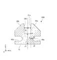
- the thickness of the gingival side wall means the bottom surface of the wire slot ( 32) and the wire slot side surface (31a) on the gingival side is point A, the edge of the gingival recessed portion (40a) closest to the occlusal side is point B, and the wire slot (30) passes through point A If the intersection of a straight line parallel to the line that bisects the side-occlusal side and a perpendicular line passing through point B and perpendicular to the straight line is point C, the distance between point B and point C (d2) Say.
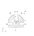
- FIG. 4 is an enlarged view showing a case where the corner where the bottom surface of the wire slot and the side surface of the wire slot on the gingival side intersect has an arc-shaped curved surface portion (R), and is an enlarged view showing the vicinity of the corner.
- the orthodontic bracket (100) in this embodiment has an arc-shaped curved surface portion (R) at the corner where the wire slot bottom surface (32) and the gum-side wire slot side surface (31a) intersect. may have In other words, the wire slot bottom surface (32) and the gum-side wire slot side surface (31a) may have a flat surface portion (P1) and an arcuate curved surface portion (R1).
- the point A which is the corner where the wire slot bottom surface (32) and the gingival-side wire slot side surface (31a) intersect, is the flat portion (P1) and the curved surface portion (R1) of the wire slot gingival side surface (31a). refers to the boundary point between
- the esthetic property derived from the translucency of the bracket made of the sintered body of the present embodiment is, for example, a value obtained by converting the linear transmittance of the wire slot after hot water treatment at 140 ° C. for 72 hours to a sample thickness of 1 mm. (hereinafter also referred to as “converted transmittance”).
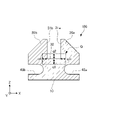
- 5 and 6 are schematic side views for explaining an example of a method of preparing a measurement sample for measuring the converted transmittance of an orthodontic bracket. A measurement sample for measuring the converted transmittance of the bracket was taken out by cutting so as to include the chain-dotted frame region (Q) shown in FIG. 5 or 6 .
- Region (Q) shown in FIG. 5 comprises dimension (q1), dimension (q2), dimension (q3) and dimension (q4).
- the dimension (q1) is 0.1 mm or more, preferably 0.3 mm or more, from the wire slot bottom surface (32) toward the tooth surface side. Moreover, it is preferably 3 mm or less, 2 mm or less, or 1 mm or less. Any combination of these upper and lower limits may be used. Therefore, the dimension (q1) is, for example, 0.1 mm or more and 3 mm or less, preferably 0.1 mm or more and 2 mm or less, more preferably 0.3 mm or more and 1 mm or less from the wire slot bottom surface (32) toward the tooth surface side direction.
- the dimension (q2) is preferably 0.1 mm or more, or 0.3 mm or more from the wire slot bottom surface (32) toward the lip/buccal direction. Moreover, it is preferably 3 mm or less, 2 mm or less, or 1 mm or less. Any combination of these upper and lower limits may be used. Therefore, the dimension (q2) is, for example, 0.1 mm or more and 3 mm or less, preferably 0.1 mm or more and 2 mm or less, more preferably 0.3 mm or more and 1 mm from the wire slot bottom surface (32) toward the lip/buccal direction. It has the following dimensions.
- the dimension (q3) should be 0.1 mm or more, or 0.3 mm or more from the corner where the wire slot bottom surface (32) and the gum-side wire slot side surface (31a) intersect toward the tooth surface side. is preferred. Moreover, it is preferably 3 mm or less, 2 mm or less, or 1 mm or less. Any combination of these upper and lower limits may be used. Accordingly, the dimension (q3) is, for example, 0.1 mm or more and 3 mm or less, preferably 0 .1 mm to 2 mm, more preferably 0.3 mm to 1 mm.
- the dimension (q4) is 0.1 mm or more, or 0.3 mm or more in the occlusal direction from the corner where the wire slot bottom surface (32) and the occlusal side wire slot side surface (31b) intersect.
- it is preferably 3 mm or less, 2 mm or less, or 1 mm or less. Any combination of these upper and lower limits may be used. Therefore, the dimension (q4) is, for example, 0.1 mm or more and 3 mm or less, preferably 0.1 mm or more and 3 mm or less, preferably 0.1 mm or more, toward the occlusion side direction from the corner where the wire slot bottom surface (32) and the occlusion side wire slot side surface (31b) intersect.
- the depth dimension (not shown) of the wire slot (30) in the region (Q) is not particularly limited, and may be, for example, the same dimension as the width of the wire slot (30) of the orthodontic bracket (100). may
- a measurement sample for measuring the converted transmittance should have a surface roughness Ra ⁇ 0.02 ⁇ m.
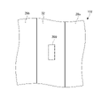
- the linear transmittance in the measurement of the converted transmittance is measured using a general microspectrophotometer (eg, MSV-370, manufactured by JASCO Corporation). Measurement can be performed by irradiating the surface to be bonded (hereinafter also referred to as “bonding surface”) with incident light and adjusting the aperture position so that transmitted light can be obtained from the bottom surface of the wire slot.
- the aperture position refers to an area range through which linear light is transmitted in the measurement of the converted transmittance.
- FIG. 7 is an enlarged view showing the vicinity of the aperture position for explaining the aperture position of the sintered body when measuring the converted transmittance of the orthodontic bracket. As shown in FIG. 7, the aperture (200) location is located within the wire slot bottom surface (32) of the sintered body (102).
- Measurement conditions include the following conditions.
- Light source Halogen lamp Measurement wavelength: 600 nm
- the converted transmittance of the bracket is obtained by measuring the linear transmittance of the measurement sample in the measurement of the converted transmittance described above, and converting it into a linear transmittance at a sample thickness of 1 mm by the following formula (1).
- thickness x mm for example, x is 0.1 to 3, preferably x is 0.2 to 2, more preferably x is 0.3 to 1, more preferably x is 0.3 to 0 .5 or less
- equation (1) the converted transmittance of a sample with a thickness of 1 mm can be calculated.
- T1 ( Tx *0.01) ⁇ (1/x)*100 [%] (1)
- T 1 Converted transmittance [%]
- T x measured value of in-line transmittance at sample thickness x mm [%]
- x measurement sample thickness [mm]
- the measurement sample may be one that has been subjected to aging treatment.
- aging treatment after the surface roughness is Ra ⁇ 0.02 ⁇ m, pure water and the sample are placed in a stainless steel pressure container, which is further placed in an autoclave and held at 140 ° C. for 72 hours. good.
- the converted transmittance is preferably 10% or more, 12% or more, or 14% or more, and preferably 25% or less, or 18% or less.
- the bottom surface of the wire slot means a flat portion.
- the curved surface portion is not included in the wire slot bottom surface.
- the sintered body of this embodiment has high strength.
- the torque strength of the orthodontic bracket made of the sintered body of this embodiment may vary depending on the dimensions of the bracket.
- the torque strength in a bracket depends primarily on the in-out dimensions and gingival sidewall thickness of the bracket. Specifically, the larger the in-out dimension and the thickness of the side wall on the gingival side, the larger the value of the torque strength tends to be.
- the bracket of the present embodiment preferably has a torque strength of 1.0 kgf cm or more when both the in-out dimension and the gingival side wall thickness are 1.0 mm or less, and the in-out dimension and the gingival side wall thickness are When both are 0.6 mm or less, it is more preferably 1.0 kgf ⁇ cm or more.
- the weight is preferably 1.0 kgf ⁇ cm or more.
- the torque strength of the bracket made of the sintered body of this embodiment is obtained by pushing a stainless steel wire into the wire slot and determining the value when the bracket breaks.
- the deviation of torque strength in the bracket is preferably 0.30 or less, further 0.25 or less, or further 0.20 or less, and may be 0.01 or more or 0.05 or more.
- the deviation of the torque strength of the bracket made of the sintered body of this embodiment is obtained by measuring the torque strength of a plurality of brackets (for example, 2 or more and 50 or less). It is the absolute value of the difference from the average value of , and is the largest value.
- the flexural strength of the sintered body of this embodiment is preferably 500 MPa or more, more preferably 600 MPa or more.
- the bending strength of the sintered body of the present embodiment is preferably 800 MPa or more, more preferably 1000 MPa or more, because the applicable applications are widened.
- the sintered body of the present embodiment preferably has a fracture toughness equal to or higher than that of a translucent zirconia sintered body made of cubic zirconia, such as a sintered body containing 8 mol% yttrium and the balance being zirconia. .
- the sintered body of this embodiment can be used as a member in which a conventional translucent zirconia sintered body is used.
- the fracture toughness of the sintered body of the present embodiment is 1.7 MPa m 0.5 or more, further 1.8 MPa m 0.5 or more, further 2 MPa m 0.5 or more, or further 2.2 MPa ⁇ m 0.5 or more, 2.5 MPa ⁇ m 0.5 or less, or 3.0 MPa ⁇ m 0.5 or less.
- the fracture toughness can be measured by either the IF method or the SEPB method according to JIS R1607, and values measured by the SEPB method are particularly preferred.
- the fracture toughness measured by the IF method shows a higher value than the fracture toughness value measured by the SEPB method.
- the sintered body of the present embodiment has both excellent mechanical strength and translucency. It can be used for applications of sintered bodies, and can be particularly suitably used for orthodontic members and orthodontic brackets that require aesthetics.
- a mixing step of mixing a zirconia raw material, a stabilizing element raw material, and a lanthanum raw material to obtain a mixed powder, a molding step of molding the obtained mixed powder to obtain a molded body, and a molded body obtained are described.
- the sintered body of the present embodiment can be manufactured by a manufacturing method characterized by including a temperature decreasing step of decreasing the temperature at a temperature decreasing rate of more than /min.
- the zirconia raw material, the stabilizing element raw material, and the lanthanum raw material are mixed to obtain a mixed powder.
- any mixing method may be used, and either wet mixing or dry mixing may be used.
- the mixing method is preferably wet mixing, more preferably wet mixing by at least one of a wet ball mill and a wet stirring mill, since the resulting mixed powder has higher uniformity.
- the zirconia raw material is zirconia or its precursor, and zirconia powder having a BET specific surface area of 4 m 2 /g or more and 20 m 2 /g or less can be mentioned.
- the stabilizing element raw material is a powder of a compound containing at least one selected from the group of yttrium, scandium, calcium, magnesium and cerium, preferably a powder of a compound containing yttrium or a precursor thereof.
- the zirconia raw material is preferably zirconia powder containing a stabilizing element (hereinafter also referred to as "stabilizing element-containing zirconia").
- a zirconia powder becomes a zirconia raw material and a stabilizing element raw material.
- the stabilizing element contained in the zirconia powder is preferably at least one selected from the group consisting of yttrium, scandium, calcium, magnesium and cerium, more preferably yttrium.
- the stabilizing element-containing zirconia powder is a zirconia powder containing 1 mol % or more and 6 mol % or less of a stabilizing element in terms of oxide, and has a BET specific surface area of 4 m 2 /g or more and 20 m 2 /g and 1 mol % or more and 6 mol % or less. is preferably a zirconia powder containing a stabilizing element of The stabilizing element content of the stabilizing element-containing zirconia powder is preferably 2 mol % or more and 5 mol % or less, more preferably 2 mol % or more and 4 mol % or less, in terms of oxide.
- the lanthanum raw material can include compounds containing lanthanum, and at least one selected from the group consisting of lanthanum oxide, lanthanum hydroxide, lanthanum nitrate, lanthanum sulfate, lanthanum chloride, lanthanum carbonate, and pyrochlore-type La 2 Zr 2 O 7 . preferably at least one selected from the group consisting of lanthanum hydroxide, lanthanum oxide and La 2 Zr 2 O 7 , more preferably at least one of lanthanum hydroxide and lanthanum oxide, still more preferably It is lanthanum hydroxide.
- the mixed powder may contain an alumina raw material.
- Alumina raw materials include compounds containing aluminum, preferably at least one selected from the group consisting of alumina, aluminum hydroxide, aluminum carbonate and spinel, more preferably alumina.
- Preferable alumina includes at least one of ⁇ -type alumina and ⁇ -type alumina, and further ⁇ -type alumina.
- the composition of the mixed powder may be any desired proportion, but in terms of oxide, zirconia should be 84 mol % or more and 98 mol % or less, the stabilizing element should be 1 mol % or more and 6 mol % or less, and the lanthanum should be 1 mol % or more and 10 mol % or less. mentioned.
- Preferred mixed powder compositions include the following molar compositions. Zirconia: 90 mol% or more and 95 mol% or less, preferably 92 mol% or more and 94 mol% or less Stabilizing element: 2 mol% or more and 5 mol% or less, preferably 2 mol% or more and 4 mol% or less Lanthanum: 2 mol% or more and 6.5 mol% or less, preferably is 3 mol% or more and 5 mol% or less
- the stabilizing element in the above composition is preferably yttrium.
- the mixed powder is molded to obtain a compact.
- Any molding method can be used as long as a molded article having a desired shape can be obtained.
- the molding method at least one selected from the group of press molding, injection molding, sheet molding, extrusion molding, and cast molding can be mentioned, and at least one of press molding and injection molding is preferred.
- the shape of the molded body is arbitrary, but for example, it may be discoidal, cylindrical, polyhedral, or the like, orthodontic brackets, semiconductor manufacturing jigs, and other complex shapes, depending on the purpose and application. can be exemplified.
- a sintered body having a highly smooth surface is obtained by placing the compact in the inner container and sintering the inner container in the outer container.
- the container during sintering is designed to prevent the smoothness of the surface of the sintered body from being lowered due to the material being sintered being in direct contact with the flow of the atmosphere medium in the sintering furnace. It is used to avoid an increase in the surface roughness of the sintered body due to the direct exposure of the sintered material to the gas flow.
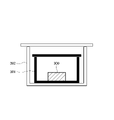
- FIG. 8 is a schematic diagram showing an example of the arrangement of compacts in the sintering process.
- the compact (300) is placed inside an inner container (301), and the inner container (301) is placed inside an outer container (302).
- the inner container may have any shape that allows the molded body to be placed therein, and the outer container may have any shape that allows the inner container to be placed therein.
- the inner container and the outer container may be any container other than a sealed container, that is, a container that does not interrupt the flow of atmospheric gas. It is a container in which the atmosphere in the container does not form a closed system with respect to the atmosphere in the sintering furnace. Specific containers include lidded containers such as lidded crucibles and lidded saggers.
- the inner container (301) and the outer container (302) are each shown as a container with a lid, and the inner container (301) accommodates the object to be sintered.
- the outer container (302) accommodates the inner container (301) and the lid is placed without sealing the outer container (302).
- the material of the inner container is at least one of metal oxides and metal nitrides, preferably metal oxides, more preferably alumina, zirconia, mullite, yttria, spinel, magnesia, silicon nitride and boron nitride. more preferably at least one selected from the group consisting of alumina, zirconia, mullite and yttria, more preferably yttria.
- the material of the outer container is at least one selected from the group consisting of carbon, metal oxides and metal nitrides. Among them, carbon is preferable as the material of the outer container from the viewpoint of obtaining a sintered body having both excellent mechanical strength and translucency and suppressing variations in mechanical strength between sintered bodies. Further, the outer container is preferably made of carbon because it is less expensive than the outer container made of metal oxide or metal nitride and has high industrial utility value. In the production method of the present embodiment, since the container is doubled, the carbon derived from the container does not adhere to the surface of the object to be sintered, and a sintered body having excellent mechanical strength and translucency is easily obtained. Become. Furthermore, the present inventors have found that the use of a carbon outer container suppresses variations in mechanical strength between sintered bodies.
- the primary sintered body may be placed in the inner container instead of the molded body. That is, in the secondary sintering, the primary sintered body may be placed in the inner container, and the inner container may be placed in the outer container and sintered.
- the compact obtained in the molding step is sintered at a sintering temperature of 1650°C or higher.
- a sintering temperature 1650°C or higher.
- the sintering temperature is 1650° C. or higher, preferably 1700° C. or higher, more preferably 1725° C. or higher, and even more preferably 1750° C. or higher.
- the sintering temperature can be exemplified by 2000° C. or less, 1900° C. or less, or 1800° C. or less.
- the sintering method is arbitrary as long as it is sintered at the above sintering temperature.
- Examples of the sintering method include at least one selected from the group of pressureless sintering, pressure sintering and vacuum sintering, and pressureless sintering and pressure sintering are preferred.
- a sintering method performed only by normal pressure sintering (hereinafter also referred to as a “single-step sintering method”), or a primary sintered body by firing the molded body at 1000 ° C. or more and less than 1650 ° C.
- a sintering process including primary sintering to obtain and secondary sintering of sintering the primary sintered body at 1650° C. or higher (hereinafter also referred to as “two-step sintering method”) can be mentioned.
- a sintered body may be obtained by subjecting the sintering process to pressureless sintering.
- Atmospheric sintering is a method of sintering by simply heating the object to be sintered without applying any external force during sintering.
- the molded body obtained in the molding step may be sintered under normal pressure to obtain a sintered body.
- the sintering temperature may be 1600°C or higher, preferably 1700°C or higher and 1900°C or lower.
- the sintering atmosphere may be either an oxidizing atmosphere or a reducing atmosphere. Since it is simple, it is preferable to use an air atmosphere.
- the two-stage sintering method is a method in which a compact is primarily sintered to form a primary sintered body, and the primary sintered body is secondary sintered.
- the compact is preferably sintered at a temperature of 1000°C or higher and lower than 1650°C.
- the atmosphere of the primary sintering is preferably an oxidizing atmosphere or a reducing atmosphere, more preferably an oxidizing atmosphere, and more preferably an air atmosphere.
- Preferable primary sintering includes pressureless sintering in air at a temperature of 1000° C. or higher or 1400° C. or higher and below 1650° C. or 1520° C. or lower.
- the resulting primary sintered body has a fine structure. In addition to this, pores are less likely to form in the crystal grains of the primary sintered body.
- the primary sintered body is sintered at 1650°C or higher, preferably 1700°C or higher, more preferably 1725°C or higher, and even more preferably 1750°C or higher.
- the secondary sintering temperature is 2000° C. or lower, preferably 1900° C. or lower, more preferably 1800° C. or lower. By setting the secondary sintering temperature to 2000° C. or less, coarse crystal grains are less likely to form.
- the secondary sintering is preferably a hot isostatic pressing (hereinafter also referred to as "HIP") treatment.
- HIP hot isostatic pressing
- the HIP treatment time (hereinafter also referred to as "HIP time”) is 10 minutes or more or 30 minutes or more, and 4 hours or less or 2 hours or less. Since the pores of the sintered body are sufficiently removed during the HIP treatment, the HIP time is preferably 10 minutes or longer.
- Argon gas, nitrogen gas, oxygen, etc. can be exemplified as the pressure medium for HIP processing (hereinafter also simply referred to as "pressure medium"), but general argon gas is convenient.
- the pressure of HIP treatment (hereinafter also referred to as "HIP pressure") is preferably 5 MPa or higher, more preferably 50 MPa or higher.
- HIP pressure is preferably 5 MPa or higher, more preferably 50 MPa or higher.
- the HIP pressure is 200 MPa or less when a normal HIP apparatus is used.
- the temperature is lowered from the secondary sintering temperature to 1000°C at a temperature lowering rate of more than 1°C/min.
- the secondary sintering temperature to 1650° C. or higher and the temperature drop rate to be higher than 1° C./min, preferably 5° C./min or higher, and more preferably 8° C./min or higher, the zirconia crystal grains of the sintered body are A sintered body having cubic domains and tetragonal domains and having high translucency can be obtained. If the temperature drop rate is 1° C./min or less, precipitates and monoclinic crystals are formed, so that the resulting sintered body has low translucency.
- the temperature drop rate from the firing temperature to 1000°C is preferably 10°C/min or more, more preferably 15°C/min or more, and still more preferably. is 30° C./min or more, and more preferably 50° C./min or more. Although there is no particular upper limit for the rate of temperature drop, 150° C./min or less or 100° C./min or less can be exemplified.
- the manufacturing method of the present embodiment may have an annealing step of heat-treating the sintered body after the cooling step.
- the annealing step includes treating the sintered body at 900° C. or higher and 1200° C. or lower, preferably 980° C. or higher and 1030° C. or lower in an oxidizing atmosphere.
- the sintered body obtained by the above method tends to have less variation in mechanical strength.
- the torque strength deviation in the bracket-shaped sintered body of the present embodiment is 0.30 or less, further 0.25 or less, or further 0.20 or less, and , 0.01 or more, or 0.05 or more.
- the torque intensity deviation is preferably within the above range, and is more preferably smaller. Since it is possible to effectively suppress the occurrence of strength defects in the bracket, the minimum torque strength of the sintered body is maintained at a high level, improving the reliability of the sintered body. improves.
- the XRD pattern was measured using a general powder X-ray diffractometer (device name: Ultima III, manufactured by Rigaku Corporation).
- the crystalline XRD peak was detected by specifying the 2 ⁇ of the peak top in the analysis of the XRD pattern using general analysis software (product name: JADE7, manufactured by MID).
- the average crystallite size of the sintered body sample was obtained using the Scherrer formula for the XRD pattern obtained by the same measurement method as for the identification of the crystal phase.
- D K ⁇ /(( ⁇ B) ⁇ cos ⁇ )
- K is the Scherrer constant (1.0)
- ⁇ is the wavelength of CuK ⁇ (0.15418 nm)
- ⁇ is the half width (°)
- B is the device constant (0. 1177°)
- ⁇ is the diffraction angle (°) of the main peak.
- the main peak the peak corresponding to the cubic (111) plane of zirconia and the overlapping peak corresponding to the tetragonal (111) plane were regarded as a single peak.
- FWHM was determined using Integral Analysis for Windows (Version 6.0) manufactured by Rigaku.
- a bracket-shaped sample was used to measure the torque strength.
- a bracket was secured to the pedestal as the sample and a stainless steel wire (0.019 x 0.025 inch) was threaded through the wire slot of the sample and secured.
- the surface of the wire slot of the sample was in the state after HIP treatment.
- a stainless steel wire was pushed through the wire slot and the torque strength was measured when the bracket was broken. Measurements were carried out by preparing one or more samples for each example and comparative example. A certain torque intensity deviation was obtained.
- test piece A test piece-shaped sintered body (30 mm ⁇ 25 mm, 1.0 mm thick rectangular plate-shaped molded body, hereinafter simply referred to as "test piece") by a method according to the method of JIS K321-1. rate was measured.
- the linear transmittance was measured by irradiating the measurement sample with visible light having a wavelength of 600 nm and detecting the luminous flux transmitted through the measurement sample with an integrating sphere.
- the linear transmittance thus obtained was defined as "1 mm thickness transmittance”.
- a general haze meter (apparatus name: haze meter NDH2000, manufactured by NIPPON DENSOKU) was used for the measurement. Prior to the measurement, both surfaces of the test piece were surface-ground and then mirror-polished using diamond abrasive grains of 9 ⁇ m, 6 ⁇ m and 1 ⁇ m in order so that the surface roughness Ra was 0.02 ⁇ m or less.
- the converted transmittance was measured using bracket-shaped sintered bodies subjected to aging treatment as samples. Aging was performed by placing pure water and a sample in a stainless steel pressure vessel, further placing this in an autoclave, and holding at 140° C. for 72 hours.
- a microspectrophotometer (device name: MSV-370, manufactured by JASCO Corporation) was used. Incident light was applied to the bonding surface of the measurement sample, and the aperture position was adjusted so that transmitted light was obtained from the bottom surface of the wire slot. The linear transmittance thus obtained was taken as the linear transmittance of the bracket. Measurement was performed under the following conditions. Light source: Halogen lamp Measurement wavelength: 600 nm Aperture size: 400 x 100 ⁇ m (100 ⁇ m is the width direction of the wire slot bottom) Light transmission direction: From the bonding surface (polished finish) to the bottom surface of the wire slot (unprocessed) Number of measurement points: 5 points
- the converted transmittance was determined as the linear transmittance at a sample thickness of 1 mm, that is, the linear transmittance when the sample thickness was converted to 1 mm by the following formula (1).
- T1 ( Tx *0.01) ⁇ (1/x)*100 [%] (1)
- T 1 Converted transmittance [%]
- T x Linear transmittance of bracket at sample thickness x mm [%]
- x measurement sample thickness [mm]
- Example 1 La(OH)3 powder was added to the zirconia powder so that the mass ratio of the La(OH) 3 powder to the 3 mol% yttrium-containing zirconia powder (BET specific surface area: 7 m 2 /g) was 11.7 mass%. was dispersed in pure water to prepare a slurry having a solid content of 50% by mass. The resulting slurry was pulverized by a wet ball mill using zirconia balls with a diameter of 10 mm. The average particle size of the obtained mixed powder was 0.4 ⁇ m. This slurry was dried and granulated with a spray dryer to prepare raw material powder.
- Each of the obtained compacts was heated at 450°C in air and then fired at 1500°C in air for 2 hours to obtain a primary sintered body.
- the obtained primary sintered body was placed inside an inner container made of yttria.
- the inner container containing the primary sintered body was placed inside the outer container made of carbon.
- the primary sintered body was subjected to HIP treatment in a 99.9% argon gas atmosphere at a heating rate of 600°C/h, a HIP temperature of 1750°C, a HIP pressure of 150 MPa, and a holding time of 1 hour.
- the temperature was lowered from the sintering temperature to room temperature to obtain a HIP-treated body.
- the temperature drop rate from the HIP temperature to 1000°C was 45°C/min.
- the obtained HIP-processed body was heat-treated in the air at 1000° C. for 1 hour to obtain a colorless and translucent sintered body.
- the obtained sintered body was a zirconia sintered body in which 4.1 mol % of lanthanum and 2.9 mol % of yttrium were solid-dissolved, and had an average crystal grain size of 45 ⁇ m. From the pattern, the average crystallite size was 27 nm. Since the average crystallite size was smaller than the average crystal grain size, it was confirmed that the obtained sintered body contained tetragonal domains and cubic domains in the crystal grains.
- the test piece-shaped sintered body thus obtained was measured for linear transmittance, and the bracket-shaped sintered body was measured for torque strength and linear transmittance.
- a measurement sample with a sample thickness q1 of 0.3 mm was taken out by polishing cutting, and after aging treatment, the in-line transmittance T 0.3 [%] at a sample thickness of 0.3 mm was measured.
- the in-line transmittance T 1 [%] when the thickness of the sample was 1 mm was calculated according to the formula (1) and used as the converted transmittance.
- Example 2 A sintered body of this example was obtained in the same manner as in Example 1, except that the bracket-shaped compact was injection molded with an I/O of 0.813 mm and a gingival side wall thickness of 0.813 mm. The test piece-shaped sintered body thus obtained was measured for linear transmittance, and the bracket-shaped sintered body was measured for torque strength and converted transmittance.
- alumina orthodontic bracket which is a standard orthodontic bracket, was produced by the following method.
- a high-purity alumina powder (purity 99.99%, BET specific surface area 14 m 2 /g) was mixed with an organic binder containing wax, plasticizer and thermoplastic resin to obtain an alumina compound.
- the obtained alumina compound was injection-molded into a rectangular plate-shaped molded body of 30 mm x 25 mm and a thickness of 1.0 mm, and a bracket-shaped molding having dimensions of I/O: 0.508 mm and side wall thickness on the gingival side: 0.508 mm. got a body
- the obtained molded body After heating the obtained molded body at 450° C. in air, it was fired at 1300° C. in air for 2 hours to obtain a primary sintered body.
- the obtained primary sintered body was subjected to HIP treatment in a 99.9% argon gas atmosphere at a heating rate of 600° C./h, a HIP temperature of 1500° C., a HIP pressure of 150 MPa, and a holding time of 1 hour. After the HIP treatment, the temperature was lowered from the sintering temperature to room temperature to obtain a HIP-treated body, which was used as the sintered body of this comparative example.
- the sintered body of this comparative example was colorless and translucent.
- the test piece-shaped sintered body thus obtained was measured for linear transmittance, and the bracket-shaped sintered body was measured for torque strength and converted transmittance.
- a measurement sample with a sample thickness q1 of 0.3 mm was taken out by polishing cutting, and the linear transmittance T 0.3 [%] at a sample thickness of 0.3 mm was measured.
- the in-line transmittance T 1 [%] when the thickness of the sample was 1 mm was calculated according to (1) and used as the converted transmittance.
- Comparative example 2 A sintered body of this comparative example was obtained in the same manner as in Comparative Example 1, except that the bracket-shaped molded body was injection molded with an I/O of 0.814 mm and a gingival side wall thickness of 0.814 mm. The test piece-shaped sintered body thus obtained was measured for linear transmittance, and the bracket-shaped sintered body was measured for torque strength and converted transmittance.
- Comparative example 3 A sintered body of this comparative example was obtained in the same manner as in comparative example 1 except that the HIP temperature was set to 1300°C.
- the test piece-shaped sintered body thus obtained was measured for linear transmittance, and the bracket-shaped sintered body was measured for torque strength and converted transmittance.
- a measurement sample with a sample thickness q1 of 0.3 mm was taken out by polishing cutting, and the linear transmittance T 0.3 [%] at a sample thickness of 0.3 mm was measured.
- the in-line transmittance T 1 [%] when the thickness of the sample was 1 mm was calculated according to (1) and used as the converted transmittance.
- Comparative example 4 A sintered body of this comparative example was obtained in the same manner as in comparative example 3, except that the shape of the bracket-shaped molded body was injection molded with I/O: 0.814 mm and the thickness of the side wall on the gingival side: 0.814 mm. The test piece-shaped sintered body thus obtained was measured for linear transmittance, and the bracket-shaped sintered body was measured for torque strength and converted transmittance.
- Comparative example 5 No outer container was used, a zirconia container with a lid was used as the inner container, and the shape of the bracket-shaped molded body was I / O: 1.016 mm, the thickness of the side wall on the gingival side: 0.864 mm.
- a sintered body made of zirconia in which 4.1 mol% of lanthanum and 2.9 mol% of yttrium are solid-dissolved was obtained in the same manner as in Example 1, except that the injection molding was performed as a sintered body of this comparative example. It was formed. The test piece-shaped sintered body thus obtained was measured for linear transmittance, and the bracket-shaped sintered body was measured for torque strength.
- Comparative example 6 The outer container made of yttria was used instead of the outer container made of carbon, and the shape of the bracket-shaped molded body was injection-molded with I/O: 1.016 mm and the thickness of the side wall on the gingival side: 0.864 mm. Except for this, a zirconia sintered body in which 4.1 mol % of lanthanum and 2.9 mol % of yttrium are solid-dissolved was obtained in the same manner as in Example 1, and this was used as the sintered body of this comparative example. The test piece-shaped sintered body thus obtained was measured for linear transmittance, and the bracket-shaped sintered body was measured for torque strength.
- Table 1 shows the composition of the sintered body, the dimensions of the orthodontic bracket, and the HIP temperature in Examples and Comparative Examples.
- Table 2 shows the results of the torque strength, linear transmittance and converted transmittance of the sintered bodies in Examples and Comparative Examples.
- Table 3 also shows the torque strength per dimension of the bracket, calculated by dividing the torque strength by the in-out dimension or the thickness of the side wall on the gingival side.
Landscapes
- Chemical & Material Sciences (AREA)
- Engineering & Computer Science (AREA)
- Ceramic Engineering (AREA)
- Manufacturing & Machinery (AREA)
- Health & Medical Sciences (AREA)
- Materials Engineering (AREA)
- Structural Engineering (AREA)
- Organic Chemistry (AREA)
- Composite Materials (AREA)
- Oral & Maxillofacial Surgery (AREA)
- Inorganic Chemistry (AREA)
- Dentistry (AREA)
- Epidemiology (AREA)
- Life Sciences & Earth Sciences (AREA)
- Animal Behavior & Ethology (AREA)
- General Health & Medical Sciences (AREA)
- Public Health (AREA)
- Veterinary Medicine (AREA)
- Dental Tools And Instruments Or Auxiliary Dental Instruments (AREA)
- Compositions Of Oxide Ceramics (AREA)
Priority Applications (5)
| Application Number | Priority Date | Filing Date | Title |
|---|---|---|---|
| EP22811347.8A EP4349800A4 (en) | 2021-05-27 | 2022-05-25 | SINTERED BODY AND METHOD FOR THE PRODUCTION THEREOF AND ORTHODONTIC BRACKET |
| KR1020237041802A KR20240013752A (ko) | 2021-05-27 | 2022-05-25 | 소결체 및 그 제조 방법, 그리고 치열 교정 브래킷 |
| JP2023523501A JPWO2022250077A1 (enExample) | 2021-05-27 | 2022-05-25 | |
| CN202280036946.6A CN117377644A (zh) | 2021-05-27 | 2022-05-25 | 烧结体及其制造方法、以及正畸托槽 |
| US18/562,976 US20240300859A1 (en) | 2021-05-27 | 2022-05-25 | Sintered body, method for producing the same, and orthodontic bracket |
Applications Claiming Priority (2)
| Application Number | Priority Date | Filing Date | Title |
|---|---|---|---|
| JP2021-089267 | 2021-05-27 | ||
| JP2021089267 | 2021-05-27 |
Publications (1)
| Publication Number | Publication Date |
|---|---|
| WO2022250077A1 true WO2022250077A1 (ja) | 2022-12-01 |
Family
ID=84229864
Family Applications (1)
| Application Number | Title | Priority Date | Filing Date |
|---|---|---|---|
| PCT/JP2022/021371 Ceased WO2022250077A1 (ja) | 2021-05-27 | 2022-05-25 | 焼結体及びその製造方法、並びに歯列矯正ブラケット |
Country Status (6)
| Country | Link |
|---|---|
| US (1) | US20240300859A1 (enExample) |
| EP (1) | EP4349800A4 (enExample) |
| JP (1) | JPWO2022250077A1 (enExample) |
| KR (1) | KR20240013752A (enExample) |
| CN (1) | CN117377644A (enExample) |
| WO (1) | WO2022250077A1 (enExample) |
Citations (10)
| Publication number | Priority date | Publication date | Assignee | Title |
|---|---|---|---|---|
| JP2000095564A (ja) * | 1998-09-18 | 2000-04-04 | Daiichi Kigensokagaku Kogyo Co Ltd | ジルコニア質焼結体及びその製造方法ならびに粉砕部材用材料 |
| JP2008050247A (ja) | 2006-07-25 | 2008-03-06 | Tosoh Corp | 高強度ジルコニア焼結体および製造方法 |
| JP2009269812A (ja) | 2008-04-09 | 2009-11-19 | Tosoh Corp | 透光性ジルコニア焼結体及びその製造方法並びに用途 |
| JP2011051881A (ja) * | 2009-08-07 | 2011-03-17 | Tosoh Corp | 透明ジルコニア焼結体及びその製造方法、並びにその用途 |
| JP2013515671A (ja) * | 2009-12-29 | 2013-05-09 | スリーエム イノベイティブ プロパティズ カンパニー | イットリウム及びランタンをドープしたジルコニア系材料 |
| JP2017105689A (ja) | 2015-01-15 | 2017-06-15 | 東ソー株式会社 | 透光性ジルコニア焼結体及びその製造方法並びにその用途 |
| JP2017214266A (ja) * | 2016-05-25 | 2017-12-07 | 東ソー株式会社 | 透光性ジルコニア焼結体及びその製造方法並びにその用途 |
| JP2018002495A (ja) * | 2016-06-27 | 2018-01-11 | 東ソー株式会社 | 着色透光性ジルコニア焼結体及びその製造方法並びにその用途 |
| JP2020001988A (ja) | 2018-07-02 | 2020-01-09 | 東ソー株式会社 | ジルコニア焼結体及びその製造方法 |
| JP2021089267A (ja) | 2020-06-03 | 2021-06-10 | 五郎 五十嵐 | 放射性物質を封入する金属製容器 |
Family Cites Families (3)
| Publication number | Priority date | Publication date | Assignee | Title |
|---|---|---|---|---|
| JP3850564B2 (ja) * | 1998-09-22 | 2006-11-29 | 松下電器産業株式会社 | トイレ装置 |
| JP5125065B2 (ja) * | 2006-02-17 | 2013-01-23 | 東ソー株式会社 | 透明ジルコニア焼結体 |
| JP7473094B2 (ja) * | 2022-01-18 | 2024-04-23 | 東ソー株式会社 | 焼結体及びその製造方法 |
-
2022
- 2022-05-25 JP JP2023523501A patent/JPWO2022250077A1/ja active Pending
- 2022-05-25 KR KR1020237041802A patent/KR20240013752A/ko active Pending
- 2022-05-25 WO PCT/JP2022/021371 patent/WO2022250077A1/ja not_active Ceased
- 2022-05-25 CN CN202280036946.6A patent/CN117377644A/zh active Pending
- 2022-05-25 EP EP22811347.8A patent/EP4349800A4/en active Pending
- 2022-05-25 US US18/562,976 patent/US20240300859A1/en active Pending
Patent Citations (10)
| Publication number | Priority date | Publication date | Assignee | Title |
|---|---|---|---|---|
| JP2000095564A (ja) * | 1998-09-18 | 2000-04-04 | Daiichi Kigensokagaku Kogyo Co Ltd | ジルコニア質焼結体及びその製造方法ならびに粉砕部材用材料 |
| JP2008050247A (ja) | 2006-07-25 | 2008-03-06 | Tosoh Corp | 高強度ジルコニア焼結体および製造方法 |
| JP2009269812A (ja) | 2008-04-09 | 2009-11-19 | Tosoh Corp | 透光性ジルコニア焼結体及びその製造方法並びに用途 |
| JP2011051881A (ja) * | 2009-08-07 | 2011-03-17 | Tosoh Corp | 透明ジルコニア焼結体及びその製造方法、並びにその用途 |
| JP2013515671A (ja) * | 2009-12-29 | 2013-05-09 | スリーエム イノベイティブ プロパティズ カンパニー | イットリウム及びランタンをドープしたジルコニア系材料 |
| JP2017105689A (ja) | 2015-01-15 | 2017-06-15 | 東ソー株式会社 | 透光性ジルコニア焼結体及びその製造方法並びにその用途 |
| JP2017214266A (ja) * | 2016-05-25 | 2017-12-07 | 東ソー株式会社 | 透光性ジルコニア焼結体及びその製造方法並びにその用途 |
| JP2018002495A (ja) * | 2016-06-27 | 2018-01-11 | 東ソー株式会社 | 着色透光性ジルコニア焼結体及びその製造方法並びにその用途 |
| JP2020001988A (ja) | 2018-07-02 | 2020-01-09 | 東ソー株式会社 | ジルコニア焼結体及びその製造方法 |
| JP2021089267A (ja) | 2020-06-03 | 2021-06-10 | 五郎 五十嵐 | 放射性物質を封入する金属製容器 |
Non-Patent Citations (1)
| Title |
|---|
| See also references of EP4349800A4 |
Also Published As
| Publication number | Publication date |
|---|---|
| KR20240013752A (ko) | 2024-01-30 |
| TW202248177A (zh) | 2022-12-16 |
| CN117377644A (zh) | 2024-01-09 |
| JPWO2022250077A1 (enExample) | 2022-12-01 |
| US20240300859A1 (en) | 2024-09-12 |
| EP4349800A4 (en) | 2025-06-04 |
| EP4349800A1 (en) | 2024-04-10 |
Similar Documents
| Publication | Publication Date | Title |
|---|---|---|
| US10273191B2 (en) | Translucent zirconia sintered body, method for manufacturing same, and use thereof | |
| US9902654B2 (en) | ZrO2-Al2O3-based ceramic sintered compact and production method thereof | |
| TWI791473B (zh) | 稀土類氟氧化物燒結體及其製造方法 | |
| US20110027742A1 (en) | Translucent zirconia sintered body, process for producing the same, and use of the same | |
| JP6911290B2 (ja) | 着色透光性ジルコニア焼結体及びその製造方法並びにその用途 | |
| JP6747121B2 (ja) | 透光性ジルコニア焼結体及びその製造方法並びにその用途 | |
| JP7845566B2 (ja) | 仮焼体、及び焼結体の製造方法 | |
| JP2018002528A (ja) | 透光性ジルコニア焼結体及びその製造方法並びにその用途 | |
| US11014855B2 (en) | Transparent AlN sintered body and method for producing the same | |
| JP7135501B2 (ja) | ジルコニア焼結体及びその製造方法 | |
| EP4467527A1 (en) | Sintered body and method for producing same | |
| US20240300859A1 (en) | Sintered body, method for producing the same, and orthodontic bracket | |
| JP6772591B2 (ja) | 透光性ジルコニア焼結体及びその製造方法並びにその用途 | |
| JP7798224B2 (ja) | チタン及びイットリウム固溶ジルコニア焼結体 | |
| WO2026034554A1 (ja) | セラミックス材料、光学部材、ヘッドマウントディスプレイ、及びセラミックス材料の製造方法 | |
| WO2024203161A1 (ja) | リサイクルジルコニアの製造方法 |
Legal Events
| Date | Code | Title | Description |
|---|---|---|---|
| 121 | Ep: the epo has been informed by wipo that ep was designated in this application |
Ref document number: 22811347 Country of ref document: EP Kind code of ref document: A1 |
|
| WWE | Wipo information: entry into national phase |
Ref document number: 202280036946.6 Country of ref document: CN |
|
| WWE | Wipo information: entry into national phase |
Ref document number: 2023523501 Country of ref document: JP |
|
| ENP | Entry into the national phase |
Ref document number: 20237041802 Country of ref document: KR Kind code of ref document: A |
|
| WWE | Wipo information: entry into national phase |
Ref document number: 1020237041802 Country of ref document: KR |
|
| NENP | Non-entry into the national phase |
Ref country code: DE |
|
| WWE | Wipo information: entry into national phase |
Ref document number: 2022811347 Country of ref document: EP |
|
| ENP | Entry into the national phase |
Ref document number: 2022811347 Country of ref document: EP Effective date: 20240102 |