WO2022249787A1 - 基板処理装置および基板処理方法 - Google Patents
基板処理装置および基板処理方法 Download PDFInfo
- Publication number
- WO2022249787A1 WO2022249787A1 PCT/JP2022/017904 JP2022017904W WO2022249787A1 WO 2022249787 A1 WO2022249787 A1 WO 2022249787A1 JP 2022017904 W JP2022017904 W JP 2022017904W WO 2022249787 A1 WO2022249787 A1 WO 2022249787A1
- Authority
- WO
- WIPO (PCT)
- Prior art keywords
- polishing pad
- pad
- amount
- holder
- wear
- Prior art date
- Legal status (The legal status is an assumption and is not a legal conclusion. Google has not performed a legal analysis and makes no representation as to the accuracy of the status listed.)
- Ceased
Links
Images





Classifications
-
- B—PERFORMING OPERATIONS; TRANSPORTING
- B24—GRINDING; POLISHING
- B24B—MACHINES, DEVICES, OR PROCESSES FOR GRINDING OR POLISHING; DRESSING OR CONDITIONING OF ABRADING SURFACES; FEEDING OF GRINDING, POLISHING, OR LAPPING AGENTS
- B24B37/00—Lapping machines or devices; Accessories
- B24B37/04—Lapping machines or devices; Accessories designed for working plane surfaces
- B24B37/07—Lapping machines or devices; Accessories designed for working plane surfaces characterised by the movement of the work or lapping tool
- B24B37/10—Lapping machines or devices; Accessories designed for working plane surfaces characterised by the movement of the work or lapping tool for single side lapping
-
- B—PERFORMING OPERATIONS; TRANSPORTING
- B24—GRINDING; POLISHING
- B24B—MACHINES, DEVICES, OR PROCESSES FOR GRINDING OR POLISHING; DRESSING OR CONDITIONING OF ABRADING SURFACES; FEEDING OF GRINDING, POLISHING, OR LAPPING AGENTS
- B24B37/00—Lapping machines or devices; Accessories
- B24B37/005—Control means for lapping machines or devices
-
- B—PERFORMING OPERATIONS; TRANSPORTING
- B24—GRINDING; POLISHING
- B24B—MACHINES, DEVICES, OR PROCESSES FOR GRINDING OR POLISHING; DRESSING OR CONDITIONING OF ABRADING SURFACES; FEEDING OF GRINDING, POLISHING, OR LAPPING AGENTS
- B24B37/00—Lapping machines or devices; Accessories
- B24B37/11—Lapping tools
- B24B37/20—Lapping pads for working plane surfaces
-
- B—PERFORMING OPERATIONS; TRANSPORTING
- B24—GRINDING; POLISHING
- B24B—MACHINES, DEVICES, OR PROCESSES FOR GRINDING OR POLISHING; DRESSING OR CONDITIONING OF ABRADING SURFACES; FEEDING OF GRINDING, POLISHING, OR LAPPING AGENTS
- B24B49/00—Measuring or gauging equipment for controlling the feed movement of the grinding tool or work; Arrangements of indicating or measuring equipment, e.g. for indicating the start of the grinding operation
- B24B49/10—Measuring or gauging equipment for controlling the feed movement of the grinding tool or work; Arrangements of indicating or measuring equipment, e.g. for indicating the start of the grinding operation involving electrical means
-
- B—PERFORMING OPERATIONS; TRANSPORTING
- B24—GRINDING; POLISHING
- B24B—MACHINES, DEVICES, OR PROCESSES FOR GRINDING OR POLISHING; DRESSING OR CONDITIONING OF ABRADING SURFACES; FEEDING OF GRINDING, POLISHING, OR LAPPING AGENTS
- B24B49/00—Measuring or gauging equipment for controlling the feed movement of the grinding tool or work; Arrangements of indicating or measuring equipment, e.g. for indicating the start of the grinding operation
- B24B49/18—Measuring or gauging equipment for controlling the feed movement of the grinding tool or work; Arrangements of indicating or measuring equipment, e.g. for indicating the start of the grinding operation taking regard of the presence of dressing tools
- B24B49/186—Measuring or gauging equipment for controlling the feed movement of the grinding tool or work; Arrangements of indicating or measuring equipment, e.g. for indicating the start of the grinding operation taking regard of the presence of dressing tools taking regard of the wear of the dressing tools
-
- B—PERFORMING OPERATIONS; TRANSPORTING
- B24—GRINDING; POLISHING
- B24B—MACHINES, DEVICES, OR PROCESSES FOR GRINDING OR POLISHING; DRESSING OR CONDITIONING OF ABRADING SURFACES; FEEDING OF GRINDING, POLISHING, OR LAPPING AGENTS
- B24B53/00—Devices or means for dressing or conditioning abrasive surfaces
- B24B53/017—Devices or means for dressing, cleaning or otherwise conditioning lapping tools
-
- H—ELECTRICITY
- H10—SEMICONDUCTOR DEVICES; ELECTRIC SOLID-STATE DEVICES NOT OTHERWISE PROVIDED FOR
- H10P—GENERIC PROCESSES OR APPARATUS FOR THE MANUFACTURE OR TREATMENT OF DEVICES COVERED BY CLASS H10
- H10P52/00—Grinding, lapping or polishing of wafers, substrates or parts of devices
Definitions
- CMP Chemical Mechanical Polishing
- Patent Document 1 discloses that in a face-up CMP apparatus, a substrate is polished by rotating a polishing pad having a diameter smaller than that of the substrate and bringing it into contact with the substrate. Further, Patent Document 2 discloses measuring the thickness of a polishing pad in a face-up type CMP apparatus.
- the conventional technology does not consider measuring the wear amount of the polishing pad with a simple structure.
- Patent Document 2 measures the thickness of the polishing pad by providing a contact stylus displacement meter in the CMP apparatus. Therefore, a dedicated space is required for arranging the contact stylus displacement gauge, which increases the size and complexity of the entire CMP apparatus.
- one object of the present application is to measure the amount of wear of a polishing pad with a simple structure.
- a table for supporting a substrate with a surface to be polished facing upward, a pad holder for holding a polishing pad for polishing the substrate supported by the table, and the pad holder and an elevating mechanism for elevating the polishing pad held by the elevating mechanism, and the abrasion of the polishing pad based on a value correlated with the behavior of the elevating mechanism until the polishing pad is lowered by the elevating mechanism until it contacts a reference surface and a wear amount measuring member for measuring the amount of wear.
- FIG. 1 is a perspective view schematically showing the overall configuration of a substrate processing apparatus according to one embodiment
- FIG. 1 is a plan view schematically showing the overall configuration of a substrate processing apparatus according to one embodiment
- FIG. 1 is a schematic perspective view of a multi-axis arm according to one embodiment
- FIG. 1 is a schematic perspective view of a pad holder according to one embodiment
- FIG. 4 is a cross-sectional view schematically showing a pad holder according to one embodiment
- FIG. 4 is a diagram schematically showing wear measurement of a polishing pad according to the first embodiment
- 10 is a diagram schematically showing wear measurement of a polishing pad according to a third embodiment
- 9 is a flow chart showing wear measurement of a polishing pad according to the third embodiment
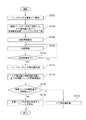
- 9 is a flow chart showing wear measurement of a polishing pad according to the third embodiment
- 10 is a flow chart showing abrasion measurement of a polishing pad according to a modified example of the third embodiment
- FIG. 1 is a perspective view schematically showing the overall configuration of a substrate processing apparatus according to one embodiment.
- FIG. 2 is a plan view schematically showing the overall configuration of the substrate processing apparatus according to one embodiment.
- the substrate processing apparatus 1000 shown in FIGS. 1 and 2 has a table 100, a multi-axis arm 200, support members 300A and 300B, a dresser 500, and a film thickness measuring device (end point detector) 600. Note that the multi-axis arm 200 is omitted in FIG. 1 for clarity of illustration.
- the table 100 is a disc-shaped member for supporting the disc-shaped substrate WF to be processed so that the surface to be polished of the disc-shaped substrate WF faces vertically upward.
- the table 100 has a support surface 100a for supporting the back surface of the substrate WF opposite to the surface to be polished, and is rotatable by a drive mechanism such as a motor (not shown).
- a plurality of holes 102 are formed in the support surface 100 a , and the table 100 is configured to be able to vacuum-suck the substrate WF through the holes 102 .
- the substrate processing apparatus 1000 of this embodiment is a face-up type substrate processing apparatus that polishes a substrate WF with the surface to be polished of the substrate WF facing upward.
- FIG. 3 is a schematic perspective view of a multi-axis arm according to one embodiment.
- the multi-axis arm 200 is a member that holds a plurality of processing tools for performing various types of processing on the substrate WF supported by the table 100, and is adjacent to the table 100. placed.
- the multi-axis arm 200 of this embodiment includes a large-diameter disk-shaped polishing pad 222 for polishing the substrate WF, a disk-shaped cleaning tool 232 for cleaning the substrate WF, and a final polishing of the substrate WF.
- the multi-axis arm 200 is supported by a swing shaft 210 extending in a direction (height direction) perpendicular to the substrate WF, a rotation drive mechanism 212 such as a motor for rotating the swing shaft 210 , and the swing shaft 210 . and a first arm 220 , a second arm 230 , a third arm 240 , and a fourth arm 250 radially disposed about the swing shaft 210 .
- a rotary shaft 224 extending in the height direction is attached to the first arm 220 , and a disk-shaped pad holder 226 is attached to the tip of the rotary shaft 224 .
- a pad holder 226 holds a large-diameter polishing pad 222 .
- the multi-axis arm 200 includes a holder elevating mechanism 227 for elevating the pad holder 226 with respect to the substrate WF.
- the holder elevating mechanism 227 can be implemented by a known mechanism such as a servomotor.
- the multi-axis arm 200 also has a pad rotation mechanism 229 for rotating the pad holder 226 .
- the pad rotation mechanism 229 can be realized by a known mechanism such as a motor, and can rotate the pad holder 226 by rotating the rotary shaft 224 .
- the multi-axis arm 200 has nozzles 228 arranged around a pad holder 226 .
- the nozzle 228 is configured to supply a polishing liquid (slurry) to the substrate WF.
- the nozzles 228 are arranged in the swing path of the first nozzle 228-1 arranged on the swing path of the pad holder 226 and the swing path of the pad holder 226 on the opposite side of the pad holder 226 from the first nozzle 228-1. and a second nozzle 228-2.
- the first nozzle 228-1 and the second nozzle 228-2 are each configured to supply polishing liquid to the surface to be polished of the substrate WF.
- a rotating shaft 234 extending in the height direction is attached to the second arm 230 , and a disk-shaped cleaning tool holder 236 is attached to the tip of the rotating shaft 234 .
- the cleaning tool holder 236 holds the cleaning tool 232 .
- the multi-axis arm 200 includes a holder elevating mechanism 237 for elevating the cleaning tool holder 236 with respect to the substrate WF.
- the holder elevating mechanism 237 can be implemented by a known mechanism such as a servomotor.
- the multi-axis arm 200 also includes a cleaning tool rotation mechanism 239 for rotating the cleaning tool holder 236 .
- the cleaning tool rotating mechanism 239 can be realized by a known mechanism such as a motor, and can rotate the cleaning tool holder 236 by rotating the rotation shaft 234 .
- the multi-axis arm 200 includes an atomizer 238 for supplying cleaning liquid around the cleaning implement holder 236 .
- the atomizers 238 are provided on both sides in the swinging direction of the cleaning tool holder 236 with the cleaning tool holder 236 interposed therebetween, and are configured to discharge the cleaning liquid onto the substrate WF.
- a rotary shaft 244 extending in the height direction is attached to the third arm 240 , and a disk-shaped pad holder 246 is attached to the tip of the rotary shaft 244 .
- a pad holder 246 holds a small-diameter polishing pad 242 .
- the multi-axis arm 200 includes a holder elevating mechanism 247 for elevating the pad holder 246 with respect to the substrate WF.
- the holder elevating mechanism 247 can be implemented by a known mechanism such as a servomotor.
- the multi-axis arm 200 also has a pad rotation mechanism 249 for rotating the pad holder 246 .
- the pad rotating mechanism 249 can be implemented by a known mechanism such as a motor, and can rotate the pad holder 246 by rotating the rotating shaft 244 .
- a photographing member 252 is held by the fourth arm 250 .
- the multi-axis arm 200 has a nozzle 248 for supplying polishing liquid around the pad holder 246 .
- the nozzles 248 are arranged in the swing path of the first nozzle 248-1 arranged on the swing path of the pad holder 246 and the swing path of the pad holder 246 on the side opposite to the first nozzle 248-1 across the pad holder 246. and a second nozzle 248-2.
- the first nozzle 248-1 and the second nozzle 248-2 are configured to supply polishing liquid to the surface to be polished of the substrate WF.
- the first arm 220, the second arm 230, the third arm 240, and the fourth arm 250 swing counterclockwise by 90 degrees in plan view.
- the rotation drive mechanism 212 can move any one of the large-diameter polishing pad 222, the cleaning tool 232, the small-diameter polishing pad 242, and the imaging member 252 onto the substrate WF by rotating the swing shaft 210. can. Further, the rotation drive mechanism 212 can move the polishing pad 222 or the polishing pad 242 onto the dresser 500 by rotating the swing shaft 210 .
- the rotary drive mechanism 212 rotates the swing shaft 210 alternately clockwise and counterclockwise to rotate the first arm 220, the second arm 230, the third arm 240, and the fourth arm. It has the function of a swing mechanism that swings the arm 250 .
- the rotation drive mechanism 212 alternately rotates the swing shaft 210 clockwise and counterclockwise while the polishing pad 222, cleaning tool 232, or polishing pad 242 is positioned on the substrate WF.
- the polishing pad 222 (pad holder 226), cleaning tool 232 (cleaning tool holder 236), or polishing pad 242 (pad holder 246) can be swung with respect to the substrate WF.
- the polishing pad 222, cleaning tool 232, or polishing pad 242 is rotated and oscillated in the radial direction of the substrate WF by the rotation drive mechanism 212, that is, reciprocated along an arc, but is limited to this. not.
- the swing mechanism may have a configuration for linearly swinging the polishing pad 222, cleaning tool 232, or polishing pad 242 in the radial direction of the substrate, that is, reciprocating along a straight line.
- the substrate processing apparatus 1000 rotates the table 100 and the polishing pad 222, and rotates while pressing the polishing pad 222 against the substrate WF by the holder elevating mechanism 227.
- the mechanism 212 swings the polishing pad 222 to polish the substrate WF.
- the substrate processing apparatus 1000 includes a first support member 300A arranged on the swing path of the polishing pad 222 outside the table 100, and a first support member 300A with the table 100 interposed therebetween. 300A and a second support member 300B disposed in the swing path of the polishing pad 222 opposite to 300A.
- the first support member 300A and the second support member 300B are symmetrical with respect to the substrate WF. Therefore, hereinafter, the first support member 300A and the second support member 300B will be collectively referred to as the support member 300 as appropriate.
- the function of the support member 300 in the case of swinging the large-diameter polishing pad 222 with respect to the substrate WF will be described below as an example, but the same applies to the cleaning tool 232 or the small-diameter polishing pad 242. .
- the support member 300 is a member for supporting the polishing pad 222 that is swung to the outside of the table 100 by the rotation of the swing shaft 210 . That is, when polishing the substrate WF, the substrate processing apparatus 1000 rocks (overhangs) the polishing pad 222 to the outside of the substrate WF, thereby uniformly polishing the surface to be polished of the substrate WF. Configured. Here, when the polishing pad 222 is overhanging, the pressure of the polishing pad 222 is concentrated on the peripheral edge of the substrate WF due to various factors such as tilting of the pad holder 226, and the surface to be polished of the substrate WF becomes uniform. It may not be polished. Therefore, the substrate processing apparatus 1000 of this embodiment is provided with support members 300 on both sides of the table 100 for supporting the polishing pad 222 overhanging the outside of the substrate WF.
- the first support member 300A and the second support member 300B respectively have support surfaces 301a and 301b capable of supporting the entire polishing surface 222c of the polishing pad 222 in contact with the substrate WF. That is, each of the support surfaces 301a and 301b has an area larger than the area of the polishing surface 222c of the polishing pad 222. Therefore, even if the polishing pad 222 completely overhangs the outside of the substrate WF, the polishing surface 222c does not reach the polishing surface 222c. The whole is supported by support surfaces 301a and 301b.
- the entire polishing surface of the polishing pad 222 is supported in contact with the substrate WF while the polishing pad 222 is swinging on the substrate WF, and the polishing pad 222 swings to the outside of the table 100. Since the entire polishing surface is supported by the support member 300 even when the substrate WF is being swung, it does not protrude from the areas of the surface to be polished and the support surfaces 301a and 301b of the substrate WF during rocking.
- the substrate processing apparatus 1000 includes a film thickness measuring instrument 600 for measuring the film thickness profile of the polished surface of the substrate WF while polishing the substrate WF.
- the film thickness gauge 600 can be configured with various sensors such as eddy current sensors or optical sensors.
- a rotating shaft 610 extending in the height direction is arranged adjacent to the table 100 .
- Rotating shaft 610 is rotatable about its axis by a rotation driving mechanism such as a motor (not shown).
- a swing arm 620 is attached to the rotating shaft 610 , and the film thickness measuring instrument 600 is attached to the tip of the swing arm 620 .
- the film thickness measuring instrument 600 is configured to swivel around the axis of the rotating shaft 610 as the rotating shaft 610 rotates. Specifically, the film thickness measuring instrument 600 can be swung along the radial direction of the substrate WF by the rotation of the rotary shaft 610 during polishing of the substrate WF. The film thickness measuring instrument 600 swings to a position retracted from the substrate WF when the polishing pad 222 is swinging over the substrate WF, and when the polishing pad 222 is not swinging over the substrate WF, the film thickness measuring device 600 swings. configured to rock on. That is, the film thickness measuring instrument 600 can oscillate on the substrate WF at a timing that does not interfere with the polishing pad 222 oscillating on the substrate WF. A film thickness profile can be measured over time. The film thickness measuring instrument 600 can detect the polishing end point of the substrate WF when the measured film thickness profile of the substrate WF reaches a desired film thickness profile.
- the dresser 500 is arranged in the pivot path of the polishing pads 222 , 242 due to the rotation of the oscillating shaft 210 .
- the dresser 500 is a disc-shaped member having diamond particles or the like strongly electrodeposited on its surface for dressing the polishing pads 222 and 242 .
- Dresser 500 is configured to be rotated by a rotation driving mechanism such as a motor (not shown). Pure water can be supplied to the surface of the dresser 500 from a nozzle (not shown).
- the substrate processing apparatus 1000 rotates the dresser 500 while supplying pure water from a nozzle to the dresser 500 , rotates the polishing pads 222 and 242 , and swings them against the dresser 500 while pressing the polishing pads 222 and 242 against the dresser 500 .
- the polishing pads 222 and 242 are scraped off by the dresser 500 and the polishing surfaces of the polishing pads 222 and 242 are dressed.
- FIG. 4 is a perspective view schematically showing a pad holder according to one embodiment
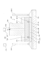
- FIG. 5 is a cross-sectional view schematically illustrating a pad holder according to one embodiment
- the configuration of the pad holder 226 will be described below, and the pad holder 246 has the same configuration.
- the pad holder 226 includes a disk-shaped first holder body 221-1 attached to the lower end of the rotary shaft 224, and a circular holder body 221-1 provided below the first holder body 221-1. and a plate-shaped second holder body 221-2.
- the multi-axis arm 200 has an elevating mechanism 260 for elevating the polishing pad 222 held by the pad holder 226 .
- Lifting mechanism 260 includes holder lifting mechanism 227 , described above, configured to lift polishing pad 222 by raising and lowering pad holder 226 .
- the elevating mechanism 260 also includes a bag member (airbag 223) for elevating the polishing pad 222 by expanding and contracting due to the inflow and outflow of fluid (for example, air).
- the airbag 223 is arranged so as to be sandwiched between the first holder body 221-1 and the second holder body 221-2.
- the airbag 223 is not limited to this embodiment, and may be attached to the pad holder 226 .
- a channel 224a communicating with the airbag 223 is formed in the rotating shaft 224 and the first holder main body 221-1.
- the multi-axis arm 200 is adapted to lower the polishing pad 222 and adjust the pressing force of the polishing pad 222 against the substrate WF by supplying gas from a fluid source (not shown) to the airbag 223 through the flow path 224a. It has become.
- a disk-shaped pad table 225 is attached to the lower surface of the second holder main body 221-2. Specifically, a magnet 221-2a is embedded in the second holder body 221-2, and a magnet 225a is embedded in the pad table 225. As shown in FIG. The pad table 225 is detachably attached to the lower surface of the second holder main body 221-2 by the magnetic force of the magnets 221-2a and 225a. The polishing pad 222 is fixed to the bottom surface of the pad table 225 with an adhesive or the like. By providing the pad table 225, the polishing pad 222 can be easily replaced.
- the substrate processing apparatus 1000 includes a wear amount measuring member 270 for measuring the wear amount of the polishing pad 222 .
- the wear amount measuring member 270 is configured to measure the wear amount of the polishing pad 222 based on a value correlated with the behavior of the lifting mechanism 260 until the polishing pad 222 is lowered by the lifting mechanism 260 until it contacts the reference surface.
- the wear amount measuring member 270 can be configured with a general computer including an input/output device, an arithmetic device, a storage device, and the like. Details of the wear amount measuring member 270 will be described below.
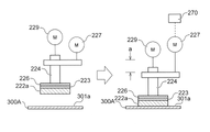
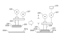
- FIGS. 6A and 6B are diagrams schematically showing wear measurement of the polishing pad according to the first embodiment.
- the wear amount measuring member 270 measures the wear amount of the polishing pad 222 using the support surface of the support member 300 (for example, the support surface 301a of the first support member 300A) as a reference surface. be able to. That is, the wear amount measuring member 270 uses information about the height of the pad holder 226 when the pad holder 226 is lowered by the holder lifting mechanism 227 until the polishing pad 222 contacts the support surface 301a of the first support member 300A. Based on this, the wear amount of the polishing pad 222 is measured.
- the pad holder 226 is arranged at the search start position in a state in which a reference polishing pad 222a (for example, a new polishing pad) is attached to the pad holder 226 .
- the wear amount measuring member 270 measures the lowering amount (a) of the pad holder 226 when the pad holder 226 is lowered by the holder lifting mechanism 227 until the polishing pad 222a contacts the support surface 301a.
- the holder lifting mechanism 227 is a servomotor with a built-in encoder in this embodiment.
- the wear amount measuring member 270 can detect contact of the polishing pad 222a with the support surface 301a based on the change in the torque value of the holder elevating mechanism 227. FIG. Also, the wear amount measuring member 270 can measure the amount of descent of the pad holder 226 based on the absolute value of the encoder of the holder elevating mechanism 227 . In the present embodiment, a new polishing pad is used as an example of the reference polishing pad 222a, but the present invention is not limited to this.
- the pad holder 226 is arranged at the search start position with the polishing pad 222b to be measured (for example, the polishing pad worn by the polishing process) attached to the pad holder 226.
- the wear amount measuring member 270 measures the lowering amount (b) of the pad holder 226 when the pad holder 226 is lowered by the holder lifting mechanism 227 until the polishing pad 222b contacts the supporting surface 301a.
- the wear amount measuring member 270 compares the descending amount (a) of the pad holder 226 with respect to the reference polishing pad 222a and the descending amount (b) of the pad holder 226 with respect to the polishing pad 222b to be measured.
- the wear amount of the polishing pad 222b is configured to measure the wear amount of the polishing pad 222b. Specifically, the amount of descent of the pad holder 226 increases by the amount of wear of the polishing pad 222 , so the amount of descent (b) minus the amount of descent (a) corresponds to the wear amount of the polishing pad 222 .
- measuring the amount of wear of the polishing pad 222 by bringing the polishing pad 222 into contact with the reference surface will be referred to as “pad search” as appropriate.
- FIG. 6 shows an example in which the amount of wear of the polishing pad 222 is measured based on the comparison of the amount of descent of the pad holder 226, the present invention is not limited to this.
- the wear amount measuring member 270 includes, for example, information about the height of the pad holder 226 when the reference polishing pad 222a contacts the support surface 301a, and information about the height of the pad holder 226 when the polishing pad 222b to be measured contacts the support surface 301a.
- the amount of wear of the polishing pad 222 can also be measured based on the comparison with the information regarding the height of the holder 226 .
- the wear amount measuring member 270 uses the support surface of the support member 300 as a reference surface. 222 wear can also be measured. Further, the wear amount measuring member 270 lowers the pad holder 226 from the search start position at the first speed, and then switches to the second speed lower than the first speed to lower the pad holder 226 for polishing. A pad 222 may be in contact with the support surface 301a. By bringing the polishing pad 222 into contact with the support surface 301a at a low speed, it is possible to prevent an excessive load from being applied to the holder elevating mechanism 227. FIG.
- the wear amount measuring member 270 performs pad searches in a plurality of states in which the rotation angle of the pad holder 226 is changed by the pad rotation mechanism 229, and the wear amount of the polishing pad 222 is calculated based on the average value of a plurality of pad searches. can also be measured. As a result, erroneous measurement of the wear amount of the polishing pad 222 due to overlapping of undulations of the polishing pad 222 and the support surface 301a can be suppressed, and the wear amount of the polishing pad 222 can be measured more accurately. .
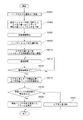
- FIG. 7A and 7B are flow charts showing wear measurement of the polishing pad according to the first embodiment.
- the substrate processing method first moves the pad holder 226 to the search start position on the support member 300A in a state where the reference polishing pad 222a is attached to the pad holder 226 (step 102). .
- the substrate processing method performs a pad search (step 104). Specifically, as described above, the pad holder 226 is lowered until the polishing pad 222a contacts the support surface 301a. to measure Subsequently, in the substrate processing method, the lowering amount (a) of the pad holder 226 at this time is stored in the storage device (step 106).
- the substrate processing method is to attach the polishing pad 222b to be measured to the pad holder 226 as shown in FIG. 7B.
- the holder 226 is moved over the substrate WF (step 202).
- the substrate processing method lowers the pad holder 226 to the polishing start position according to the lowering amount of the pad holder 226 stored in step 106 or step 220 described later (step 204).
- a step 204 lowers the pad holder 226 according to the lowering amount of the pad holder 226 stored in the step 106 when the pad search of the step 212 has never been performed for the polishing pad 222b to be measured.
- step 204 after the pad search in step 212 is performed for the polishing pad 222b to be measured, the pad holder 226 is moved according to the lowering amount of the pad holder 226 stored in step 220 in the most recent pad search. lower. This is to keep the distance between the surface to be polished of the substrate WF and the polishing surface of the polishing pad 222b constant during the polishing process. That is, before the start of polishing, the inside of the airbag 223 is in a contracted state due to the evacuation.
- step 204 the distance between the polishing surface of the polishing pad 222 and the surface to be polished of the substrate WF is kept constant (not in contact) according to the amount of wear of the polishing pad 222 measured by the wear amount measuring member 270.
- the height of the pad holder 226 is controlled. Specifically, since the polishing pad 222b is worn by the polishing process, by adjusting the height position of the pad holder 226 by the amount of wear, the surface to be polished of the substrate WF and the polishing surface of the polishing pad 222b are aligned at the start of polishing. distance can be kept constant. As a result, the force of pressing the polishing pad 222b against the surface to be polished of the substrate WF can be kept constant by the expansion of the airbag 223, so that the substrate WF can be uniformly polished.
- the substrate processing method performs polishing processing of the substrate WF (step 206). Specifically, the substrate processing method supplies the polishing liquid (slurry) from the nozzle 228 and rotates the pad holder 226 and the table 100 . Further, the substrate processing method polishes the substrate WF by swinging the pad holder 226 while pressing the polishing pad 222b against the substrate WF by supplying a fluid (for example, air) to the airbag 223 . As described above, in the substrate processing method, the height of the pad holder 226 is controlled to the polishing start position according to the amount of wear of the polishing pad 222, and then the fluid is flowed into the airbag 223 to inflate the airbag 223.
- a fluid for example, air
- the substrate processing method determines whether or not the polishing of the substrate WF is finished (step 208), and repeats the polishing process until the polishing of the substrate WF is finished.
- step 212 includes a lowering step of lowering pad holder 226 until polishing pad 222b contacts support surface 301a, as described above, with airbag 223 deflated by vacuuming.
- step 212 also includes a measurement step of measuring the amount of descent (b) of the pad holder 226 until the polishing pad 222 contacts the support surface 301a based on the absolute value of the encoder of the holder elevating mechanism 227 .
- the amount of wear of the polishing pad 222b is measured based on the amount of descent (b) of the pad holder 226 (step 214). Specifically, in the measurement step, the descending amount (a) of the pad holder 226 relative to the reference polishing pad 222a is compared with the descending amount (b) of the pad holder 226 relative to the polishing pad 222b to be measured. , the wear amount of the polishing pad 222b is measured.
- the substrate processing method determines whether or not the wear amount of the polishing pad 222b is equal to or greater than a predetermined value (step 216).
- a predetermined value when the wear amount of the polishing pad 222b is equal to or greater than the predetermined value (step 216, Yes), an alarm requesting replacement of the polishing pad 222b is issued (step 218).
- the wear amount of the polishing pad 222b is less than the predetermined value (step 216, No)
- the lowering amount (b) of the pad holder 226 is stored in the storage device (step 220).
- the wear amount measuring member 270 performs pad search using the configuration that the substrate processing apparatus 1000 originally has for the polishing process, so a special configuration for measuring the wear amount is used.
- the wear amount of the polishing pad can be measured with a simple structure.
- the pad search is performed using the hard and flat support surface of the support member 300 (for example, the support surface 301a of the first support member 300A) as a reference surface, the wear amount of the polishing pad 222 is can be measured with high accuracy.
- the pad holder 226 is moved to the polishing start position according to the amount of wear of the polishing pad 222, and then the polishing process is performed.
- the distance from the polishing surface can be kept constant.
- the force of pressing the polishing pad 222b against the surface to be polished of the substrate WF can be kept constant by the expansion of the airbag 223, so that the substrate WF can be uniformly polished.
- FIG. 7A an example of performing a pad search with respect to the polishing pad 222a serving as a reference is shown, but the present invention is not limited to this. For example, if the distance between the reference polishing pad 222a and the reference surface is known when the pad holder 226 is placed at the search start position, the pad search shown in FIG. 7A need not be performed.
- the wear amount measuring member 270 includes a photographing member (camera) 264 for photographing the airbag 223 .
- the wear amount measuring member 270 measures the expansion amount of the airbag 223 until the polishing pad 222 contacts the reference surface (for example, the surface to be polished WF-a of the substrate WF) based on the image captured by the imaging member 264.
- the wear amount of the polishing pad 222 is measured based on the measured swelling amount of the airbag 223 .
- the pad holder 226 is placed at the search start position with the reference polishing pad 222a (for example, a new polishing pad) attached to the pad holder 226 .
- the airbag 223 is deflated by vacuuming. If the search start position is too high, the polishing pad 222a will not come into contact with the surface to be polished WF-a of the substrate WF even if the airbag 223 is inflated to the maximum. It is set according to the allowable expansion amount of the airbag 223 so that it can come into contact with the polished surface WF-a of the WF.
- the wear amount measuring member 270 inflates the airbag 223 by supplying fluid to the airbag 223 . Subsequently, the wear amount measuring member 270 measures the swelling amount (c) of the airbag 223 until the polishing pad 222a contacts the surface to be polished WF-a of the substrate WF based on the image acquired by the photographing member 264. measure.
- the wear amount measuring member 270 can detect contact of the polishing pad 222a with the support surface 301a based on a change in the amount of fluid flowing into the airbag 223 or a change in the torque value of the holder elevating mechanism 227. can.
- the pad holder 226 is placed at the search start position with the polishing pad 222b to be measured (for example, the polishing pad worn by the polishing process) attached to the pad holder 226.
- the wear amount measuring member 270 inflates the airbag 223 by supplying fluid to the airbag 223 .
- the wear amount measuring member 270 measures the swelling amount (d) of the airbag 223 until the polishing pad 222a contacts the surface to be polished WF-a of the substrate WF based on the image acquired by the photographing member 264. measure.
- the wear amount measuring member 270 compares the swelling amount (c) of the airbag 223 with respect to the reference polishing pad 222a and the swelling amount (d) of the airbag 223 with respect to the polishing pad 222b to be measured. is configured to measure the wear amount of the polishing pad 222b. Specifically, since the expansion amount of the airbag 223 increases by the amount of wear of the polishing pad 222 , the expansion amount (d) ⁇ the expansion amount (c) corresponds to the abrasion amount of the polishing pad 222 .
- FIG. 9A and 9B are flow charts showing wear measurement of the polishing pad according to the second embodiment.
- the substrate processing method first moves the pad holder 226 onto the substrate WF with the reference polishing pad 222a attached to the pad holder 226 (step 302). Subsequently, the substrate processing method lowers the pad holder 226 to the search start position (step 304). Subsequently, the substrate processing method performs a pad search (step 306).
- the airbag 223 is inflated until the polishing pad 222a contacts the surface to be polished WF-a of the substrate WF, and the airbag 223 is expanded based on the image acquired by the photographing member 264.
- the swelling amount (c) is measured.
- the inflation amount (c) of the airbag 223 at this time is stored in the storage device (step 308).
- step 402 when polishing the substrate and measuring the wear amount of the polishing pad 222, as shown in FIG.
- the holder 226 is moved over the substrate WF (step 402). Subsequently, in the substrate processing method, the pad holder 226 is lowered to the search start position according to the inflation amount of the airbag 223 stored in step 308 or step 422 (step 404). In step 404, if the pad search in step 408 has never been performed for the polishing pad 222b to be measured, the pad holder 226 is lowered according to the amount of inflation of the airbag 223 stored in step 308.
- step 404 after the pad search in step 408 is performed for the polishing pad 222b to be measured, the pad holder 226 is moved according to the swelling amount of the airbag 223 stored in step 308 in the most recent pad search. lower.
- the following pad search and polishing process can be performed accurately regardless of the wear amount of the polishing pad 222. can.
- the polishing pad 222b will not adhere to the surface to be polished WF-a of the substrate WF. may not come into contact.
- the pad holder 226 is lowered in accordance with the expansion amount of the airbag 223 stored in step 308 or step 422 before executing the pad search and polishing process. Even if the amount of wear of the polishing pad 222 is greater than the allowable amount of expansion of the pad 223, the pad search and polishing process can be performed accurately. Note that if the allowable amount of expansion of the airbag 223 is sufficiently large with respect to the amount of wear of the polishing pad 222, the above concern does not occur. may be placed.
- the substrate processing method starts preparing for polishing processing of the substrate WF (step 406). Specifically, the substrate processing method supplies the polishing liquid (slurry) from the nozzle 228 and rotates the pad holder 226 and the table 100 . Subsequently, the substrate processing method performs a pad search (step 408).
- Step 408 specifically includes a lowering step of flowing fluid into the airbag 223 until the polishing pad 222b contacts the surface to be polished WF-a of the substrate WF.
- Step 408 also includes a measurement step of photographing the airbag 223 with the photographing member 264 while the airbag 223 is inflated, and measuring the expansion amount (d) of the airbag 223 based on the photographed image.
- the substrate processing method adjusts the pad holder 226 to the polishing start position based on the swelling amount (d) of the airbag 223 (step 410). This is to keep the expansion amount of the airbag 223 constant when performing the polishing process. That is, since the polishing pad 222b is worn by the polishing process, by adjusting the position of the pad holder 226 by the amount of wear, the expansion amount of the airbag 223 can be kept constant. As a result, the force of pressing the polishing pad 222b against the surface to be polished WF-a of the substrate WF can be kept constant by the expansion of the airbag 223, so that the substrate WF can be uniformly polished.
- the substrate processing method polishes the substrate WF by swinging the pad holder 226 while pressing the polishing pad 222b against the substrate WF (step 412).
- the substrate processing method determines whether or not the polishing of the substrate WF is finished (step 414), and repeats the polishing process until the polishing of the substrate WF is finished.
- the wear amount of the polishing pad 222b is calculated based on the expansion amount (d) of the airbag 223 and the search start position. is measured (measurement step 416). Specifically, the measurement step 416 compares the expansion amount (c) of the airbag 223 with respect to the reference polishing pad 222a and the expansion amount (d) of the airbag 223 with respect to the polishing pad 222b to be measured. to measure the wear amount of the polishing pad 222b.
- the substrate processing method determines whether or not the wear amount of the polishing pad 222b is equal to or greater than a predetermined value (step 418).
- a predetermined value when the wear amount of the polishing pad 222b is equal to or greater than the predetermined value (step 418, Yes), an alarm requesting replacement of the polishing pad 222b is issued (step 420).
- the wear amount of the polishing pad 222b is less than the predetermined value (step 418, No)
- the inflation amount (d) of the airbag 223 is stored in the storage device (step 422).
- the wear amount measuring member 270 performs pad search using the configuration that the substrate processing apparatus 1000 originally has for the polishing process, so a special configuration for measuring the wear amount is used.
- the wear amount of the polishing pad can be measured with a simple structure.
- the pad holder 226 is moved to the polishing start position according to the amount of wear of the polishing pad 222, and then the polishing process is performed. can be done.
- the force of pressing the polishing pad 222b against the surface to be polished of the substrate WF can be kept constant by the expansion of the airbag 223, so that the substrate WF can be uniformly polished.
- the wear amount measuring member 270 includes a flow meter 262 capable of measuring the amount of fluid flowing into the airbag 223.
- FIG. The wear amount measuring member 270 uses the flow meter 262 to measure the amount of fluid flowing into the airbag 223 until the polishing pad 222 contacts the reference surface (for example, the surface to be polished WF-a of the substrate WF). It is configured to measure the wear amount of the polishing pad 222 based on the amount of fluid inflow.
- the pad holder 226 is placed at the search start position with the reference polishing pad 222a (for example, a new polishing pad) attached to the pad holder 226 .
- the airbag 223 is deflated by vacuuming. If the search start position is too high, the polishing pad 222a will not come into contact with the surface to be polished WF-a of the substrate WF even if the airbag 223 is inflated to the maximum. It is set according to the allowable expansion amount of the airbag 223 so that it can come into contact with the polished surface WF-a of the WF.
- the wear amount measuring member 270 inflates the airbag 223 by supplying fluid to the airbag 223 . Subsequently, the wear amount measuring member 270 measures the inflow amount (e) of the fluid into the airbag 223 until the polishing pad 222a contacts the surface to be polished WF-a of the substrate WF.
- the pad holder 226 is arranged at the search start position with the polishing pad 222b to be measured (for example, the polishing pad worn by the polishing process) attached to the pad holder 226.
- the wear amount measuring member 270 inflates the airbag 223 by supplying fluid to the airbag 223 .
- the wear amount measuring member 270 measures the amount (f) of fluid flowing into the airbag 223 until the polishing pad 222a contacts the surface to be polished WF-a of the substrate WF.
- the wear amount measuring member 270 measures the amount (e) of fluid flowing into the airbag 223 with respect to the reference polishing pad 222a and the amount (f) of fluid flowing into the airbag 223 with respect to the polishing pad 222b to be measured. It is configured to measure the wear amount of the polishing pad 222b to be measured by comparison. Specifically, since the inflow amount (f) of the fluid to the airbag 223 increases by the amount of wear of the polishing pad 222, the amount that correlates with the inflow amount (f) ⁇ the inflow amount (e) is the amount of the polishing pad 222. Corresponds to the amount of wear.
- the polishing pad 222 wear amount can be determined.
- 11A and 11B are flow charts showing polishing pad wear measurement according to the third embodiment.
- the substrate processing method first moves the pad holder 226 onto the substrate WF in a state where the reference polishing pad 222a is attached to the pad holder 226 (step 502). Subsequently, the substrate processing method lowers the pad holder 226 to the search start position (step 504). Subsequently, the substrate processing method performs a pad search (step 506).
- the airbag 223 is inflated until the polishing pad 222a contacts the surface to be polished WF-a of the substrate WF, and the flowmeter 262 measures the inflow amount (e) of the fluid into the airbag 223. to measure Subsequently, the substrate processing method stores the inflow amount (e) of the fluid into the airbag 223 at this time in the storage device (step 508).
- step 602 when polishing the substrate and measuring the wear amount of the polishing pad 222, as shown in FIG.
- the holder 226 is moved over the substrate WF (step 602). Subsequently, the substrate processing method lowers the pad holder 226 to the search start position according to the amount of fluid flowing into the airbag 223 stored in step 508 or step 622 (step 604). In step 604, if the pad search in step 608 has never been performed for the polishing pad 222b to be measured, the pad holder 226 is moved according to the amount of fluid flowing into the airbag 223 stored in step 508. lower.
- step 604 after the pad search in step 608 is performed on the polishing pad 222b to be measured, the pad search is performed according to the amount of fluid flowing into the airbag 223 stored in step 608 in the most recent pad search. Lower the holder 226 . By lowering the pad holder 226 to the search start position according to the amount of fluid flowing into the airbag 223, the wear amount of the polishing pad 222 can The pad search and polishing process can be performed accurately even when .
- the substrate processing method starts preparation for the polishing process of the substrate WF (step 606). Specifically, the substrate processing method supplies the polishing liquid (slurry) from the nozzle 228 and rotates the pad holder 226 and the table 100 . Subsequently, the substrate processing method performs a pad search (step 608). Specifically, step 608 includes a lowering step of injecting fluid into the airbag 223 until the polishing pad 222b contacts the surface to be polished WF-a of the substrate WF. Step 608 also includes a measurement step of measuring the amount of fluid (f) flowing into the airbag 223 with the flow meter 262 while the airbag 223 is being inflated.
- a pad search step 608 includes a lowering step of injecting fluid into the airbag 223 until the polishing pad 222b contacts the surface to be polished WF-a of the substrate WF.
- Step 608 also includes a measurement step of measuring the amount of fluid (f) flowing into the airbag 223 with the flow meter 262 while the air
- the substrate processing method adjusts the pad holder 226 to the polishing start position based on the inflow amount (f) of the fluid into the airbag 223 (step 610).
- the height position of the pad holder 226 can be adjusted so that the inflow rate (f) of the fluid into the airbag 223 becomes a predetermined inflow rate. This is to keep the expansion amount of the airbag 223 constant when performing the polishing process. That is, since the polishing pad 222b is worn by the polishing process, by adjusting the position of the pad holder 226 by the amount of wear, the expansion amount of the airbag 223 can be kept constant.
- the substrate processing method polishes the substrate WF by swinging the pad holder 226 while pressing the polishing pad 222b against the substrate WF (step 612).
- the substrate processing method determines whether or not the polishing of the substrate WF is finished (step 614), and repeats the polishing process until the polishing of the substrate WF is finished.
- the polishing pad 222b is adjusted based on the inflow amount (f) of the fluid to the airbag 223 and the search start position. is measured (measurement step 616). Specifically, in the measuring step 616, the inflow amount (e) of fluid to the airbag 223 for the reference polishing pad 222a and the inflow amount (f) of the fluid to the airbag 223 for the polishing pad 222b to be measured , to measure the wear amount of the polishing pad 222b.
- the substrate processing method determines whether or not the wear amount of the polishing pad 222b is equal to or greater than a predetermined value (step 618).
- a predetermined value when the wear amount of the polishing pad 222b is equal to or greater than the predetermined value (step 618, Yes), an alarm requesting replacement of the polishing pad 222b is issued (step 620).
- the wear amount of the polishing pad 222b is less than the predetermined value (step 618, No)
- the amount of fluid (f) flowing into the airbag 223 is stored in the storage device (step 622). ).
- the wear amount measuring member 270 performs pad search using the configuration that the substrate processing apparatus 1000 originally has for the polishing process, so a special configuration for measuring the wear amount is used.
- the wear amount of the polishing pad can be measured with a simple structure.
- the pad holder 226 is moved to the polishing start position according to the amount of wear of the polishing pad 222, and then the polishing process is performed. can be done.
- the force of pressing the polishing pad 222b against the surface to be polished of the substrate WF can be kept constant by the expansion of the airbag 223, so that the substrate WF can be uniformly polished.
- the amount of wear of the polishing pad 222 is measured based on the amount of fluid flowing into the airbag 223 with respect to the polishing pad 222b to be measured.
- the measuring member 270 can also measure the amount of wear of the polishing pad 222 based on the amount of fluid flowing out from the airbag 223 .
- the flowmeter 262 is configured to be able to measure the flow rate of fluid from the airbag 223 .
- FIG. 11C is a flowchart showing wear measurement of the polishing pad according to the modification of the third embodiment.
- the substrate processing method starts preparing for polishing processing of the substrate WF (step 706). Specifically, the substrate processing method supplies the polishing liquid (slurry) from the nozzle 228 and rotates the pad holder 226 and the table 100 . Subsequently, the substrate processing method polishes the substrate WF by swinging the pad holder 226 while pressurizing the airbag 223 to press the polishing pad 222b against the substrate WF (step 708). The substrate processing method determines whether or not the polishing of the substrate WF is finished (step 710), and repeats the polishing process until the polishing of the substrate WF is finished.
- the substrate processing method determines whether or not the polishing of the substrate WF is finished (step 710), and repeats the polishing process until the polishing of the substrate WF is finished.
- pad search is executed (step 712). Specifically, in the substrate processing method, the outflow amount (g) of the fluid from the airbag 223 is measured by the flow meter 262 while the airbag 223 is contracted from the state where the polishing pad 222b is in contact with the surface to be polished of the substrate WF. measure.
- the wear amount of the polishing pad 222b is measured based on the outflow amount (g) of the fluid from the airbag 223 and the polishing start position (step 714). Specifically, in the substrate processing method, the amount (e) of fluid flowing into the airbag 223 with respect to the reference polishing pad 222a and the amount (g) of fluid flowing out from the airbag 223 with respect to the polishing pad 222b to be measured , to measure the wear amount of the polishing pad 222b.
- the substrate processing method determines whether or not the wear amount of the polishing pad 222b is greater than or equal to a predetermined value (step 716).
- a predetermined value when the wear amount of the polishing pad 222b is equal to or greater than the predetermined value (step 716, Yes), an alarm requesting replacement of the polishing pad 222b is issued (step 718).
- the wear amount of the polishing pad 222b is less than the predetermined value (step 716, No)
- the amount (g) of the fluid flowing out from the airbag 223 is stored in the storage device (step 720).
- the pad search may be performed each time one substrate WF is polished, or may be performed each time a predetermined number of substrates WF are polished.
- the present application provides, as one embodiment, a table for supporting a substrate with the surface to be polished facing upward, a pad holder for holding a polishing pad for polishing the substrate supported by the table, and the pad an elevating mechanism for elevating the polishing pad held by a holder; and a wear amount measuring member for measuring the wear amount.
- the present application further provides, as an embodiment, a rocking mechanism for rocking the pad holder in the radial direction of the substrate, and a polishing pad for supporting the polishing pad rocked to the outside of the table by the rocking mechanism. and a support member having a support surface of , wherein the elevating mechanism includes a holder elevating mechanism for elevating the pad holder, the reference surface is the support surface of the support member, and the wear amount is The measuring member measures the wear amount of the polishing pad based on information about the height of the pad holder when the pad holder is lowered by the holder elevating mechanism until the polishing pad contacts the support surface of the support member.
- a substrate processing apparatus is disclosed that is configured to measure a .
- the elevating mechanism includes a holder elevating mechanism for elevating the pad holder
- the reference surface is a surface to be polished of the substrate
- the wear amount measuring member comprises: The wear amount of the polishing pad is measured based on information about the height of the pad holder when the pad holder is lowered by the holder elevating mechanism until the polishing pad contacts the surface to be polished of the substrate.
- the wear amount measuring member includes information about the height of the pad holder with respect to a reference polishing pad and information about the height of the pad holder with respect to the polishing pad to be measured.
- a substrate processing apparatus configured to measure the wear amount of the polishing pad to be measured by comparison is disclosed.
- the elevating mechanism is a bag member attached to the pad holder for elevating the polishing pad by expanding and contracting due to inflow and outflow of fluid.
- the wear amount measuring member includes a photographing member for photographing the bag member, and based on the image photographed by the photographing member, the polishing pad until it contacts the reference surface.
- a substrate processing apparatus configured to measure the swelling amount of a bag member and to measure the wear amount of the polishing pad based on the measured swelling amount of the bag member.
- the wear amount measuring member compares the swelling amount of the bag member with respect to a reference polishing pad and the swelling amount of the bag member with respect to the polishing pad to be measured.
- a substrate processing apparatus configured to measure the wear amount of the polishing pad to be measured is disclosed.
- the elevating mechanism is a bag member attached to the pad holder for elevating the polishing pad by expanding and contracting due to inflow and outflow of fluid.
- the wear amount measuring member includes a flow meter capable of measuring the amount of fluid flowing into the bag member, and the amount of fluid flowing into the bag member until the polishing pad comes into contact with the reference surface.
- a substrate processing apparatus configured to measure the wear amount of the polishing pad based on the inflow amount is disclosed.
- the wear amount measuring member measures the amount of fluid flowing into the bag member with respect to a reference polishing pad and the amount of fluid flowing into the bag member with respect to a polishing pad to be measured.
- a substrate processing apparatus configured to measure the wear amount of the polishing pad to be measured by comparing .
- the wear amount measuring member is further based on a value correlated to the behavior of the lifting mechanism when the polishing pad is lifted from the state in which the polishing pad is in contact with the reference surface by the lifting mechanism.
- the elevating mechanism is a bag member attached to the pad holder, and expands and contracts due to inflow and outflow of fluid to measure the wear amount of the polishing pad.
- a bag member for raising and lowering the pad is included, and the wear amount measuring member includes a flow meter capable of measuring an outflow amount of fluid from the bag member.
- a substrate processing apparatus configured to measure the amount of wear of the polishing pad based on the amount of outflow of fluid when the member is shrunk.
- the wear amount measuring member measures the amount of fluid flowing out from the bag member with respect to a reference polishing pad and the amount of fluid flowing out from the bag member with respect to a polishing pad to be measured.
- a substrate processing apparatus configured to measure the wear amount of the polishing pad to be measured by comparing .
- the present application further provides, as an embodiment, a lowering step of lowering a polishing pad for polishing a substrate supported on a table with a surface to be polished facing upward until it contacts a reference surface by an elevating mechanism, and the lowering step. measuring the wear amount of the polishing pad based on a value correlated with the behavior of the elevating mechanism until the polishing pad comes into contact with the reference surface.
- the elevating mechanism includes a holder elevating mechanism for elevating a pad holder for holding the polishing pad, and the reference surface is swung outwardly of the table.
- a support surface of a support member for supporting a polishing pad the lowering step is configured to lower the pad holder by the holder elevating mechanism until the polishing pad contacts the support surface, and the measuring step measures the wear amount of the polishing pad based on information about the height of the pad holder when the pad holder is lowered by the holder elevating mechanism until the polishing pad contacts the support surface.
- a substrate processing method is disclosed.
- the elevating mechanism includes a holder elevating mechanism for elevating a pad holder for holding the polishing pad, the reference surface being a surface to be polished of the substrate,
- the lowering step is configured to lower the pad holder by the holder elevating mechanism until the polishing pad contacts the surface to be polished of the substrate.
- a substrate processing method configured to measure the wear amount of the polishing pad based on information about the height of the pad holder when the pad holder is lowered by the holder elevating mechanism until it contacts the .
- the elevating mechanism includes a bag member for elevating the polishing pad by expanding and contracting due to inflow and outflow of fluid
- the lowering step comprises the polishing pad.
- a fluid is caused to flow into the bag member until the pad contacts the reference surface.
- a substrate processing method configured to measure the swelling amount of the bag member until it contacts a reference surface, and measure the wear amount of the polishing pad based on the measured swelling amount of the bag member. .
- the elevating mechanism includes a bag member for elevating the polishing pad by expanding and contracting due to inflow and outflow of fluid
- the lowering step comprises the polishing pad.
- fluid is allowed to flow into the bag member until the pad contacts the reference surface
- the measuring step is based on the amount of fluid flowing into the bag member until the polishing pad contacts the reference surface.
- a substrate processing method configured to measure the amount of wear of the polishing pad by using a substrate.
- the measuring step further comprises: wear of the polishing pad based on a value correlated to behavior of the lifting mechanism when the polishing pad rises from a state in which it is in contact with the reference surface; wherein the lifting mechanism includes a bag member for lifting and lowering the polishing pad by expanding and contracting due to inflow and outflow of fluid; Disclosed is a substrate processing method configured to measure the amount of wear of the polishing pad based on the amount of fluid flowing out from the bag member when the bag member is contracted from a state in which the polishing pad is in contact with the reference surface. do.
Landscapes
- Engineering & Computer Science (AREA)
- Mechanical Engineering (AREA)
- Finish Polishing, Edge Sharpening, And Grinding By Specific Grinding Devices (AREA)
- Constituent Portions Of Griding Lathes, Driving, Sensing And Control (AREA)
- Mechanical Treatment Of Semiconductor (AREA)
Abstract
簡素な構造で研磨パッドの摩耗量を計測する。 基板処理装置1000は、被研磨面を上方に向けた基板WFを支持するためのテーブル100と、テーブル100に支持された基板WFを研磨するための研磨パッド222を保持するためのパッドホルダ226と、パッドホルダ226に保持された研磨パッド222を昇降させるための昇降機構260と、昇降機構260によって研磨パッド222を下降させて基準面に接触するまでの昇降機構260の挙動に相関する値に基づいて研磨パッド222の摩耗量を計測する摩耗量計測部材270と、を備える。
Description
本願は、基板処理装置および基板処理方法に関する。本願は、2021年5月24日出願の日本特許出願番号第2021-087056号に基づく優先権を主張する。日本特許出願番号第2021-087056号の明細書、特許請求の範囲、図面及び要約書を含む全ての開示内容は、参照により全体として本願に援用される。
半導体加工工程において用いられる基板処理装置の一種にCMP(Chemical Mechanical Polishing、化学的機械的研磨)装置が存在する。CMP装置は、基板の被研磨面が向いている方向によって「フェースアップ式(基板の被研磨面が上向きの方式)」と「フェースダウン式(基板の被研磨面が下向きの方式)」に大別され得る。
特許文献1には、フェースアップ式のCMP装置において、基板よりも小径の研磨パッドを回転させながら基板に接触させることによって基板を研磨することが開示されている。また、特許文献2には、フェースアップ式のCMP装置において、研磨パッドの厚みを計測することが開示されている。
しかしながら、従来技術は、簡素な構造で研磨パッドの摩耗量を計測することは考慮されていない。
すなわち、特許文献2に開示された技術は、CMP装置に接触触針変位計を設けて研磨パッドの厚みを計測するものである。したがって、接触触針変位計を配置するための専用スペースが必要であるから、CMP装置全体が大型化するとともに複雑化する。
そこで、本願は、簡素な構造で研磨パッドの摩耗量を計測することを1つの目的としている。
一実施形態によれば、被研磨面を上方に向けた基板を支持するためのテーブルと、前記テーブルに支持された基板を研磨するための研磨パッドを保持するためのパッドホルダと、前記パッドホルダに保持された研磨パッドを昇降させるための昇降機構と、前記昇降機構によって前記研磨パッドを下降させて基準面に接触するまでの前記昇降機構の挙動に相関する値に基づいて前記研磨パッドの摩耗量を計測する摩耗量計測部材と、を備える、基板処理装置が開示される。
以下に、本発明に係る基板処理装置および基板処理方法の実施形態を添付図面とともに説明する。添付図面において、同一または類似の要素には同一または類似の参照符号が付され、各実施形態の説明において同一または類似の要素に関する重複する説明は省略することがある。また、各実施形態で示される特徴は、互いに矛盾しない限り他の実施形態にも適用可能である。
図1は、一実施形態による基板処理装置の全体構成を概略的に示す斜視図である。図2は、一実施形態による基板処理装置の全体構成を概略的に示す平面図である。図1および図2に示される基板処理装置1000は、テーブル100と、多軸アーム200と、支持部材300A,300Bと、ドレッサ500と、膜厚計測器(終点検出器)600と、を有する。なお、図1においては、図示の明瞭化のために、多軸アーム200を省略している。
<テーブル>
テーブル100は、処理対象となる円板形状の基板WFの被研磨面が鉛直方向の上を向くように基板WFを支持するための円板形状の部材である。一実施形態において、テーブル100は、基板WFの被研磨面の反対側の裏面を支持するための支持面100aを有し、図示していないモータなどの駆動機構によって回転可能に構成される。支持面100aには複数の穴102が形成されており、テーブル100は、穴102を介して基板WFを真空吸着することができるように構成される。本実施形態の基板処理装置1000は、基板WFの被研磨面を上に向けて基板WFを研磨するフェースアップ式の基板処理装置である。
テーブル100は、処理対象となる円板形状の基板WFの被研磨面が鉛直方向の上を向くように基板WFを支持するための円板形状の部材である。一実施形態において、テーブル100は、基板WFの被研磨面の反対側の裏面を支持するための支持面100aを有し、図示していないモータなどの駆動機構によって回転可能に構成される。支持面100aには複数の穴102が形成されており、テーブル100は、穴102を介して基板WFを真空吸着することができるように構成される。本実施形態の基板処理装置1000は、基板WFの被研磨面を上に向けて基板WFを研磨するフェースアップ式の基板処理装置である。
<多軸アーム>
図3は、一実施形態による多軸アームを概略的に示す斜視図である。図2および図3に示すように、多軸アーム200は、テーブル100に支持された基板WFに対して各種処理を行うための複数の処理具を保持する部材であり、テーブル100に隣接して配置される。本実施形態の多軸アーム200は、基板WFを研磨するための大径の円板形状の研磨パッド222と、基板WFを洗浄するための円板形状の洗浄具232と、基板WFを仕上げ研磨するための小径の円板形状の研磨パッド242と、基板WFの直径を計測するための撮影部材(カメラ)252と、を保持するように構成される。
図3は、一実施形態による多軸アームを概略的に示す斜視図である。図2および図3に示すように、多軸アーム200は、テーブル100に支持された基板WFに対して各種処理を行うための複数の処理具を保持する部材であり、テーブル100に隣接して配置される。本実施形態の多軸アーム200は、基板WFを研磨するための大径の円板形状の研磨パッド222と、基板WFを洗浄するための円板形状の洗浄具232と、基板WFを仕上げ研磨するための小径の円板形状の研磨パッド242と、基板WFの直径を計測するための撮影部材(カメラ)252と、を保持するように構成される。
多軸アーム200は、基板WFに対して直交する方向(高さ方向)に伸びる揺動シャフト210と、揺動シャフト210を回転駆動するモータなどの回転駆動機構212と、揺動シャフト210に支持されており揺動シャフト210の周りに放射状に配置される第1のアーム220、第2のアーム230、第3のアーム240、および第4のアーム250と、を含む。
第1のアーム220には高さ方向に伸びる回転シャフト224が取り付けられており、回転シャフト224の先端には円板形状のパッドホルダ226が取り付けられている。パッドホルダ226には大径の研磨パッド222が保持される。多軸アーム200は、パッドホルダ226を基板WFに対して昇降させるためのホルダ昇降機構227を備える。ホルダ昇降機構227は、例えばサーボモータなどの公知の機構によって実現することができる。また、多軸アーム200は、パッドホルダ226を回転させるためのパッド回転機構229を備える。パッド回転機構229は、例えばモータなどの公知の機構によって実現することができ、回転シャフト224を回転させることによってパッドホルダ226を回転させることができる。
多軸アーム200は、パッドホルダ226の周囲に配置されたノズル228を備える。ノズル228は、研磨液(スラリー)を基板WFに対して供給するように構成される。ノズル228は、パッドホルダ226の揺動経路に配置された第1のノズル228-1と、パッドホルダ226を挟んで第1のノズル228-1と反対側のパッドホルダ226の揺動経路に配置された第2のノズル228-2と、を備える。第1のノズル228-1および第2のノズル228-2はそれぞれ、基板WFの被研磨面に対して研磨液を供給するように構成される。
第2のアーム230には高さ方向に伸びる回転シャフト234が取り付けられており、回転シャフト234の先端には円板形状の洗浄具ホルダ236が取り付けられている。洗浄具ホルダ236には洗浄具232が保持される。多軸アーム200は、洗浄具ホルダ236を基板WFに対して昇降させるためのホルダ昇降機構237を備える。ホルダ昇降機構237は、例えばサーボモータなどの公知の機構によって実現することができる。また、多軸アーム200は、洗浄具ホルダ236を回転させるための洗浄具回転機構239を備える。洗浄具回転機構239は、例えばモータなどの公知の機構によって実現することができ、回転シャフト234を回転させることによって洗浄具ホルダ236を回転させることができる。
多軸アーム200は、洗浄具ホルダ236の周囲に洗浄液を供給するためのアトマイザ238を備える。アトマイザ238は、洗浄具ホルダ236を挟んで洗浄具ホルダ236の揺動方向の両側に設けられ、洗浄液を基板WFに放出するように構成される。
第3のアーム240には高さ方向に伸びる回転シャフト244が取り付けられており、回転シャフト244の先端には円板形状のパッドホルダ246が取り付けられている。パッドホルダ246には小径の研磨パッド242が保持される。多軸アーム200は、パッドホルダ246を基板WFに対して昇降させるためのホルダ昇降機構247を備える。ホルダ昇降機構247は、例えばサーボモータなどの公知の機構によって実現することができる。また、多軸アーム200は、パッドホルダ246を回転させるためのパッド回転機構249を備える。パッド回転機構249は、例えばモータなどの公知の機構によって実現することができ、回転シャフト244を回転させることによってパッドホルダ246を回転させることができる。第4のアーム250には撮影部材252が保持される。
多軸アーム200は、パッドホルダ246の周囲に研磨液を供給するためのノズル248を備える。ノズル248は、パッドホルダ246の揺動経路に配置された第1のノズル248-1と、パッドホルダ246を挟んで第1のノズル248-1と反対側のパッドホルダ246の揺動経路に配置された第2のノズル248-2と、を備える。第1のノズル248-1および第2のノズル248-2は、基板WFの被研磨面に対して研磨液を供給するように構成される。
図2に示すように、本実施形態では、第1のアーム220、第2のアーム230、第3のアーム240、および第4のアーム250は、平面視で反時計回りに90度ずれて揺動シャフト210の周りに放射状に伸びる。回転駆動機構212は、揺動シャフト210を回転駆動することによって、大径の研磨パッド222、洗浄具232、小径の研磨パッド242、および撮影部材252のいずれかを基板WF上に移動させることができる。また、回転駆動機構212は、揺動シャフト210を回転駆動することによって、研磨パッド222または研磨パッド242をドレッサ500上に移動させることができる。また、回転駆動機構212は、揺動シャフト210を時計回りおよび反時計回りに交互に回転駆動することによって、第1のアーム220、第2のアーム230、第3のアーム240、および第4のアーム250を揺動させる揺動機構の機能を有する。具体的には、回転駆動機構212は、研磨パッド222、洗浄具232、または研磨パッド242が基板WF上に位置している状態で、揺動シャフト210を時計回りおよび反時計回りに交互に回転駆動することによって、研磨パッド222(パッドホルダ226)、洗浄具232(洗浄具ホルダ236)、または研磨パッド242(パッドホルダ246)を基板WFに対して揺動させることができる。本実施形態では、研磨パッド222、洗浄具232、または研磨パッド242を回転駆動機構212によって基板WFの径方向に旋回揺動させる、すなわち円弧に沿って往復運動させる例を示すが、これに限定されない。例えば、揺動機構は、研磨パッド222、洗浄具232、または研磨パッド242を基板の径方向に直線揺動させる、すなわち直線に沿って往復運動させるような構成を有し得る。
基板処理装置1000は、例えば研磨パッド222が基板WF上にある場合には、テーブル100を回転させるとともに研磨パッド222を回転させ、ホルダ昇降機構227によって研磨パッド222を基板WFに押圧しながら回転駆動機構212によって研磨パッド222を揺動させることによって、基板WFの研磨を行うように構成される。
<支持部材>
図1および図2に示すように、基板処理装置1000は、テーブル100の外側の研磨パッド222の揺動経路に配置された第1の支持部材300Aと、テーブル100を挟んで第1の支持部材300Aと反対側の研磨パッド222の揺動経路に配置された第2の支持部材300Bと、を含む。第1の支持部材300Aおよび第2の支持部材300Bは、基板WFを挟んで線対称になっている。このため、以下では、適宜、第1の支持部材300Aおよび第2の支持部材300Bをまとめて支持部材300として説明する。また、以下では、一例として、大径の研磨パッド222を基板WFに対して揺動させる場合の支持部材300の機能について説明を行うが、洗浄具232または小径の研磨パッド242についても同様である。
図1および図2に示すように、基板処理装置1000は、テーブル100の外側の研磨パッド222の揺動経路に配置された第1の支持部材300Aと、テーブル100を挟んで第1の支持部材300Aと反対側の研磨パッド222の揺動経路に配置された第2の支持部材300Bと、を含む。第1の支持部材300Aおよび第2の支持部材300Bは、基板WFを挟んで線対称になっている。このため、以下では、適宜、第1の支持部材300Aおよび第2の支持部材300Bをまとめて支持部材300として説明する。また、以下では、一例として、大径の研磨パッド222を基板WFに対して揺動させる場合の支持部材300の機能について説明を行うが、洗浄具232または小径の研磨パッド242についても同様である。
支持部材300は、揺動シャフト210の回転によってテーブル100の外側へ揺動された研磨パッド222を支持するための部材である。すなわち、基板処理装置1000は、基板WFを研磨する際に研磨パッド222を基板WFの外側に飛び出すまで揺動させる(オーバーハングさせる)ことによって、基板WFの被研磨面を均一に研磨するように構成される。ここで、研磨パッド222をオーバーハングさせた場合には、パッドホルダ226が傾くなど様々な要因によって基板WFの周縁部に研磨パッド222の圧力が集中して、基板WFの被研磨面が均一に研磨されないおそれがある。そこで、本実施形態の基板処理装置1000は、基板WFの外側にオーバーハングした研磨パッド222を支持するための支持部材300をテーブル100の両側に設けている。
第1の支持部材300Aおよび第2の支持部材300Bはそれぞれ、研磨パッド222の基板WFと接触する研磨面222cの全体を支持可能な支持面301a,301bを有する。すなわち、支持面301a,301bはそれぞれ、研磨パッド222の研磨面222cの面積よりも大きな面積を有しているので、研磨パッド222が完全に基板WFの外側までオーバーハングしたとしても研磨面222cの全体が支持面301a,301bに支持される。これにより、本実施形態では、研磨パッド222は、基板WF上を揺動しているときには研磨パッド222の研磨面の全体が基板WFに接触して支持されており、テーブル100の外側まで揺動しているときも研磨面の全体が支持部材300に支持されているので、揺動中に基板WFの被研磨面および支持面301a,301bの領域からはみ出さないようになっている。
<膜厚計測器>
図1および図2に示すように、基板処理装置1000は、基板WFを研磨しながら基板WFの被研磨面の膜厚プロファイルを計測するための膜厚計測器600を含む。膜厚計測器600は、渦電流式センサまたは光学式センサなどの様々なセンサで構成することができる。図1に示すように、高さ方向に伸びる回転シャフト610がテーブル100に隣接して配置されている。回転シャフト610は、図示していないモータなどの回転駆動機構によって回転シャフト610の軸周りに回転可能になっている。回転シャフト610には揺動アーム620が取り付けられおり、膜厚計測器600は、揺動アーム620の先端に取り付けられている。膜厚計測器600は、回転シャフト610の回転によって回転シャフト610の軸周りに旋回揺動するように構成される。具体的には、膜厚計測器600は、基板WFの研磨中に、回転シャフト610の回転によって基板WFの径方向に沿って揺動することができるようになっている。膜厚計測器600は、研磨パッド222が基板WF上を揺動しているときには基板WF上から退避した位置に揺動し、研磨パッド222が基板WF上を揺動していないときに基板WF上を揺動するように構成される。すなわち、膜厚計測器600は、基板WF上を揺動する研磨パッド222と干渉しないタイミングで基板WF上を揺動することができるようになっており、研磨パッド222によって研磨される基板WFの膜厚プロファイルを経時的に計測することができる。膜厚計測器600は、計測した基板WFの膜厚プロファイルが所望の膜厚プロファイルになったら、基板WFの研磨の終点を検出することができる。
図1および図2に示すように、基板処理装置1000は、基板WFを研磨しながら基板WFの被研磨面の膜厚プロファイルを計測するための膜厚計測器600を含む。膜厚計測器600は、渦電流式センサまたは光学式センサなどの様々なセンサで構成することができる。図1に示すように、高さ方向に伸びる回転シャフト610がテーブル100に隣接して配置されている。回転シャフト610は、図示していないモータなどの回転駆動機構によって回転シャフト610の軸周りに回転可能になっている。回転シャフト610には揺動アーム620が取り付けられおり、膜厚計測器600は、揺動アーム620の先端に取り付けられている。膜厚計測器600は、回転シャフト610の回転によって回転シャフト610の軸周りに旋回揺動するように構成される。具体的には、膜厚計測器600は、基板WFの研磨中に、回転シャフト610の回転によって基板WFの径方向に沿って揺動することができるようになっている。膜厚計測器600は、研磨パッド222が基板WF上を揺動しているときには基板WF上から退避した位置に揺動し、研磨パッド222が基板WF上を揺動していないときに基板WF上を揺動するように構成される。すなわち、膜厚計測器600は、基板WF上を揺動する研磨パッド222と干渉しないタイミングで基板WF上を揺動することができるようになっており、研磨パッド222によって研磨される基板WFの膜厚プロファイルを経時的に計測することができる。膜厚計測器600は、計測した基板WFの膜厚プロファイルが所望の膜厚プロファイルになったら、基板WFの研磨の終点を検出することができる。
<ドレッサ>
図1および図2に示すように、ドレッサ500は、揺動シャフト210の回転による研磨パッド222、242の旋回経路に配置される。ドレッサ500は、表面にダイヤモンド粒子などが強固に電着しており、研磨パッド222、242を目立て(ドレッシング)するための円板形状の部材である。ドレッサ500は、図示していないモータなどの回転駆動機構によって回転するように構成される。ドレッサ500の表面には図示していないノズルから純水を供給可能になっている。基板処理装置1000は、ノズルから純水をドレッサ500に供給しながらドレッサ500を回転させるとともに、研磨パッド222、242を回転させ、ドレッサ500に押圧しながらドレッサ500に対して揺動させる。これによって、ドレッサ500により研磨パッド222、242が削り取られ、研磨パッド222、242の研磨面がドレッシングされる。
図1および図2に示すように、ドレッサ500は、揺動シャフト210の回転による研磨パッド222、242の旋回経路に配置される。ドレッサ500は、表面にダイヤモンド粒子などが強固に電着しており、研磨パッド222、242を目立て(ドレッシング)するための円板形状の部材である。ドレッサ500は、図示していないモータなどの回転駆動機構によって回転するように構成される。ドレッサ500の表面には図示していないノズルから純水を供給可能になっている。基板処理装置1000は、ノズルから純水をドレッサ500に供給しながらドレッサ500を回転させるとともに、研磨パッド222、242を回転させ、ドレッサ500に押圧しながらドレッサ500に対して揺動させる。これによって、ドレッサ500により研磨パッド222、242が削り取られ、研磨パッド222、242の研磨面がドレッシングされる。
<パッドホルダ>
図4は、一実施形態によるパッドホルダを概略的に示す斜視図である。図5は、一実施形態によるパッドホルダを概略的に示す断面図である。以下、パッドホルダ226の構成を説明するが、パッドホルダ246も同様の構成を有する。
図4は、一実施形態によるパッドホルダを概略的に示す斜視図である。図5は、一実施形態によるパッドホルダを概略的に示す断面図である。以下、パッドホルダ226の構成を説明するが、パッドホルダ246も同様の構成を有する。
図5に示すように、パッドホルダ226は、回転シャフト224の下端に取り付けられた円板形状の第1のホルダ本体221-1と、第1のホルダ本体221-1の下方に設けられた円板形状の第2のホルダ本体221-2と、を備える。多軸アーム200は、パッドホルダ226に保持された研磨パッド222を昇降させるための昇降機構260を備える。昇降機構260は、パッドホルダ226を昇降させることによって研磨パッド222を昇降させるように構成された、前述のホルダ昇降機構227を含む。また、昇降機構260は、流体(例えば空気)の流入および流出に起因して膨張および収縮することによって研磨パッド222を昇降させるための袋部材(エアバッグ223)を含む。エアバッグ223は、第1のホルダ本体221-1と第2のホルダ本体221-2との間に挟まれるように配置される。ただし、エアバッグ223は、本実施形態に限らず、パッドホルダ226に取り付けられていればよい。回転シャフト224および第1のホルダ本体221-1には、エアバッグ223に連通する流路224aが形成されている。多軸アーム200は、図示していない流体源から流路224aを介してエアバッグ223に気体を供給することによって、研磨パッド222を下降させて基板WFに対する研磨パッド222の押圧力を調整できるようになっている。
図5に示すように、第2のホルダ本体221-2の下面には、円板形状のパッドテーブル225が取り付けられる。具体的には、第2のホルダ本体221-2には磁石221-2aが埋め込まれており、パッドテーブル225には磁石225aが埋め込まれている。パッドテーブル225は、磁石221-2aおよび磁石225aの磁力によって、第2のホルダ本体221-2の下面に着脱可能に取り付けられている。研磨パッド222は、パッドテーブル225の下面に接着剤などによって固定されている。パッドテーブル225を設けることによって、研磨パッド222の交換を容易に行うことができる。
図5に示すように、基板処理装置1000は、研磨パッド222の摩耗量を計測するための摩耗量計測部材270を備える。摩耗量計測部材270は、昇降機構260によって研磨パッド222を下降させて基準面に接触するまでの昇降機構260の挙動に相関する値に基づいて研磨パッド222の摩耗量を計測するように構成される。摩耗量計測部材270は、入出力装置、演算装置、記憶装置などを備える一般的なコンピュータで構成することができる。以下、摩耗量計測部材270の詳細について説明する。
<研磨パッドの摩耗計測>
図6Aおよび図6Bは、第1の実施形態による研磨パッドの摩耗計測を概略的に示す図である。図6Aおよび図6Bに示すように、摩耗量計測部材270は、支持部材300の支持面(例えば第1の支持部材300Aの支持面301a)を基準面として、研磨パッド222の摩耗量を計測することができる。すなわち、摩耗量計測部材270は、第1の支持部材300Aの支持面301aに研磨パッド222が接触するまでホルダ昇降機構227によってパッドホルダ226を下降させたときのパッドホルダ226の高さに関する情報に基づいて研磨パッド222の摩耗量を計測するように構成される。
図6Aおよび図6Bは、第1の実施形態による研磨パッドの摩耗計測を概略的に示す図である。図6Aおよび図6Bに示すように、摩耗量計測部材270は、支持部材300の支持面(例えば第1の支持部材300Aの支持面301a)を基準面として、研磨パッド222の摩耗量を計測することができる。すなわち、摩耗量計測部材270は、第1の支持部材300Aの支持面301aに研磨パッド222が接触するまでホルダ昇降機構227によってパッドホルダ226を下降させたときのパッドホルダ226の高さに関する情報に基づいて研磨パッド222の摩耗量を計測するように構成される。
具体的には、図6Aに示すように、基準となる研磨パッド222a(例えば新品の研磨パッドなど)がパッドホルダ226に取り付けられた状態で、サーチ開始位置にパッドホルダ226が配置される。続いて、摩耗量計測部材270は、支持面301aに研磨パッド222aが接触するまでホルダ昇降機構227によってパッドホルダ226を下降させたときのパッドホルダ226の下降量(a)を計測する。なお、ホルダ昇降機構227は、本実施形態では、エンコーダを内蔵したサーボモータである。摩耗量計測部材270は、ホルダ昇降機構227のトルク値の変化に基づいて支持面301aに研磨パッド222aが接触したことを検出することができる。また、摩耗量計測部材270は、ホルダ昇降機構227のエンコーダの絶対値に基づいてパッドホルダ226の下降量を計測することができる。本実施形態では、基準となる研磨パッド222aの一例として新品の研磨パッドを挙げて説明したが、これに限られない。
次に、図6Bに示すように、計測対象の研磨パッド222b(例えば研磨処理によって摩耗した研磨パッド)がパッドホルダ226に取り付けられた状態で、サーチ開始位置にパッドホルダ226が配置される。続いて、摩耗量計測部材270は、支持面301aに研磨パッド222bが接触するまでホルダ昇降機構227によってパッドホルダ226を下降させたときのパッドホルダ226の下降量(b)を計測する。摩耗量計測部材270は、基準となる研磨パッド222aに対するパッドホルダ226の下降量(a)と、計測対象の研磨パッド222bに対するパッドホルダ226の下降量(b)と、を比較することによって計測対象の研磨パッド222bの摩耗量を計測するように構成される。具体的には、研磨パッド222が摩耗した分だけパッドホルダ226の下降量は増加するので、下降量(b)-下降量(a)が研磨パッド222の摩耗量に相当する。以下、研磨パッド222を基準面に接触させて研磨パッド222の摩耗量を計測することを、適宜「パッドサーチ」という。なお、図6に示した例ではパッドホルダ226の下降量の比較に基づいて研磨パッド222の摩耗量を計測する例を示したが、これに限られない。摩耗量計測部材270は、例えば、基準となる研磨パッド222aが支持面301aに接触したときのパッドホルダ226の高さに関する情報と、計測対象の研磨パッド222bが支持面301aに接触したときのパッドホルダ226の高さに関する情報と、の比較に基づいて研磨パッド222の摩耗量を計測することもできる。
なお、本実施形態では、摩耗量計測部材270は、支持部材300の支持面を基準面とする例を示したが、これに限らず、例えば基板WFの被研磨面を基準面として、研磨パッド222の摩耗量を計測することもできる。また、摩耗量計測部材270は、サーチ開始位置から第1の速度でパッドホルダ226を下降させた後、第1の速度よりも低速の第2の速度に切り替えてパッドホルダ226を下降させて研磨パッド222を支持面301aに接触させてもよい。研磨パッド222を支持面301aに低速で接触させることにより、ホルダ昇降機構227に過大な負荷がかかることを防止することができる。また、摩耗量計測部材270は、パッド回転機構229によってパッドホルダ226の回転角度を異ならせた複数の状態でパッドサーチを行い、複数回のパッドサーチの平均値に基づいて研磨パッド222の摩耗量を計測することもできる。これにより、研磨パッド222および支持面301aの起伏の重なりなどに起因して研磨パッド222の摩耗量が誤計測されるのを抑制し、より正確に研磨パッド222の摩耗量を計測することができる。
次に、第1の実施形態による基板処理方法の手順を説明する。図7Aおよび図7Bは、第1の実施形態による研磨パッドの摩耗計測を示すフローチャートである。図7Aに示すように、基板処理方法は、まず、基準となる研磨パッド222aがパッドホルダ226に取り付けられた状態で、パッドホルダ226を支持部材300A上のサーチ開始位置に移動させる(ステップ102)。続いて、基板処理方法は、パッドサーチを実行する(ステップ104)。具体的には、上述のように、支持面301aに研磨パッド222aが接触するまでパッドホルダ226を下降させ、ホルダ昇降機構227のエンコーダの絶対値に基づいて、パッドホルダ226の下降量(a)を計測する。続いて、基板処理方法は、このときのパッドホルダ226の下降量(a)を記憶装置に記憶する(ステップ106)。
一方、基板の研磨および研磨パッド222の摩耗量の計測を行う場合には、図7Bに示すように、基板処理方法は、計測対象の研磨パッド222bがパッドホルダ226に取り付けられた状態で、パッドホルダ226を基板WF上に移動させる(ステップ202)。続いて、基板処理方法は、ステップ106または後述のステップ220で記憶したパッドホルダ226の下降量に応じた研磨開始位置へパッドホルダ226を下降させる(ステップ204)。ステップ204は、計測対象の研磨パッド222bに対して一度もステップ212のパッドサーチが行われていない場合には、ステップ106で記憶したパッドホルダ226の下降量に応じてパッドホルダ226を下降させる。一方、ステップ204は、計測対象の研磨パッド222bに対してステップ212のパッドサーチが行われた後は、直近のパッドサーチにおけるステップ220で記憶したパッドホルダ226の下降量に応じてパッドホルダ226を下降させる。これは、研磨処理を行う際に基板WFの被研磨面と研磨パッド222bの研磨面との距離を一定に保つためである。すなわち、研磨開始前には、エアバッグ223内部は真空引きにより収縮した状態になっている。ステップ204は、摩耗量計測部材270によって計測された研磨パッド222の摩耗量に応じて、研磨パッド222の研磨面と基板WFの被研磨面との距離が一定(接触していない)になるように、パッドホルダ226の高さを制御する。具体的には、研磨パッド222bは研磨処理によって摩耗するので、摩耗した分だけパッドホルダ226の高さ位置を調整することによって、研磨開始時に基板WFの被研磨面と研磨パッド222bの研磨面との距離を一定に保つことができる。その結果、エアバッグ223の膨張により研磨パッド222bを基板WFの被研磨面に押圧する力を一定に保つことができるので、基板WFを均一に研磨することができる。
続いて、基板処理方法は、基板WFの研磨処理を実行する(ステップ206)。具体的には、基板処理方法は、ノズル228から研磨液(スラリー)を供給するとともに、パッドホルダ226およびテーブル100を回転させる。さらに、基板処理方法は、エアバッグ223に流体(例えば空気)を供給することによって研磨パッド222bを基板WFに押圧しながらパッドホルダ226を揺動させることによって、基板WFを研磨する。上記のように、基板処理方法は、研磨パッド222の摩耗量に応じた研磨開始位置にパッドホルダ226の高さ制御を行った後に、エアバッグ223に流体を流入させてエアバッグ223を膨らませ、研磨パッド222を基板WFに押し付ける。したがって、研磨パッド222が消耗していても、エアバッグ223の膨らみを一定に保つことができるので、常に同じ圧力で基板WFを押圧することができる。基板処理方法は、基板WFの研磨が終了したか否かを判定し(ステップ208)、基板WFの研磨が終了するまで研磨処理を繰り返す。
一方、基板処理方法は、基板WFの研磨が終了したと判定した場合には(ステップ208、Yes)、パッドホルダ226を支持部材300A上のサーチ開始位置に移動させる(ステップ210)。続いて、基板処理方法は、パッドサーチを実行する(ステップ212)。ステップ212は、具体的には、エアバッグ223を真空引きによって収縮させた状態で、上述のように、支持面301aに研磨パッド222bが接触するまでパッドホルダ226を下降させる下降ステップを含む。また、ステップ212は、ホルダ昇降機構227のエンコーダの絶対値に基づいて、研磨パッド222が支持面301aに接触するまでのパッドホルダ226の下降量(b)を計測する計測ステップを含む。計測ステップは、パッドホルダ226の下降量(b)に基づいて、研磨パッド222bの摩耗量を計測する(ステップ214)。具体的には、計測ステップは、基準となる研磨パッド222aに対するパッドホルダ226の下降量(a)と、計測対象の研磨パッド222bに対するパッドホルダ226の下降量(b)と、を比較することによって、研磨パッド222bの摩耗量を計測する。
続いて、基板処理方法は、研磨パッド222bの摩耗量が所定値以上であるか否かを判定する(ステップ216)。基板処理方法は、研磨パッド222bの摩耗量が所定値以上である場合には(ステップ216、Yes)、研磨パッド222bの交換を要求するアラームを発出する(ステップ218)。一方、基板処理方法は、研磨パッド222bの摩耗量が所定値未満である場合には(ステップ216、No)、パッドホルダ226の下降量(b)を記憶装置に記憶する(ステップ220)。
本実施形態によれば、摩耗量計測部材270は、基板処理装置1000が研磨処理のために元々備えている構成を利用してパッドサーチを実行するため、摩耗量の計測のための特別の構成を配置する必要がなく、その結果、簡素な構造で研磨パッドの摩耗量を計測することができる。また、本実施形態によれば、硬質で平坦である支持部材300の支持面(例えば第1の支持部材300Aの支持面301a)を基準面としてパッドサーチを実行するので、研磨パッド222の摩耗量を精度よく計測することができる。また、本実施形態によれば、研磨パッド222の摩耗量に応じた研磨開始位置にパッドホルダ226を移動させてから研磨処理を行うので、研磨開始時に基板WFの被研磨面と研磨パッド222bの研磨面との距離を一定に保つことができる。その結果、エアバッグ223の膨張により研磨パッド222bを基板WFの被研磨面に押圧する力を一定に保つことができるので、基板WFを均一に研磨することができる。なお、本実施形態では、図7Aに示すように基準となる研磨パッド222aに対してパッドサーチを行う例を示したが、これに限定されない。例えば、パッドホルダ226をサーチ開始位置に配置した状態で基準となる研磨パッド222aと基準面との間の距離が既知であれば、図7Aに示すパッドサーチは行わなくてもよい。
次に、第2の実施形態の研磨パッドの摩耗計測について説明する。図8Aおよび図8Bは、第2の実施形態による研磨パッドの摩耗計測を概略的に示す図である。図8Aおよび図8Bに示すように、摩耗量計測部材270は、エアバッグ223を撮影するための撮影部材(カメラ)264を含んでいる。摩耗量計測部材270は、撮影部材264によって撮影された画像に基づいて研磨パッド222が基準面(例えば基板WFの被研磨面WF-a)に接触するまでのエアバッグ223の膨らみ量を計測し、計測されたエアバッグ223の膨らみ量に基づいて研磨パッド222の摩耗量を計測するように構成される。
具体的には、図8Aに示すように、基準となる研磨パッド222a(例えば新品の研磨パッドなど)がパッドホルダ226に取り付けられた状態で、サーチ開始位置にパッドホルダ226が配置される。このとき、エアバッグ223は真空引きにより収縮されている。なお、サーチ開始位置が高すぎるとエアバッグ223を最大限膨張させても研磨パッド222aが基板WFの被研磨面WF-aに接触しないので、図8Aにおけるサーチ開始位置は、研磨パッド222aが基板WFの被研磨面WF-aに接触できるように、エアバッグ223の許容膨張量に応じて設定される。続いて、摩耗量計測部材270は、エアバッグ223に流体を供給することによってエアバッグ223を膨らませる。続いて、摩耗量計測部材270は、撮影部材264によって取得された画像に基づいて、研磨パッド222aが基板WFの被研磨面WF-aに接触するまでのエアバッグ223の膨らみ量(c)を計測する。なお、摩耗量計測部材270は、エアバッグ223への流体の流入量の変化、またはホルダ昇降機構227のトルク値の変化に基づいて支持面301aに研磨パッド222aが接触したことを検出することができる。
次に、図8Bに示すように、計測対象の研磨パッド222b(例えば研磨処理によって摩耗した研磨パッド)がパッドホルダ226に取り付けられた状態で、サーチ開始位置にパッドホルダ226が配置される。続いて、摩耗量計測部材270は、エアバッグ223に流体を供給することによってエアバッグ223を膨らませる。続いて、摩耗量計測部材270は、撮影部材264によって取得された画像に基づいて、研磨パッド222aが基板WFの被研磨面WF-aに接触するまでのエアバッグ223の膨らみ量(d)を計測する。摩耗量計測部材270は、基準となる研磨パッド222aに対するエアバッグ223の膨らみ量(c)と、計測対象の研磨パッド222bに対するエアバッグ223の膨らみ量(d)と、を比較することによって計測対象の研磨パッド222bの摩耗量を計測するように構成される。具体的には、研磨パッド222が摩耗した分だけエアバッグ223の膨らみ量は増加するので、膨らみ量(d)-膨らみ量(c)が研磨パッド222の摩耗量に相当する。
次に、第2の実施形態による基板処理方法の手順を説明する。図9Aおよび図9Bは、第2の実施形態による研磨パッドの摩耗計測を示すフローチャートである。図9Aに示すように、基板処理方法は、まず、基準となる研磨パッド222aがパッドホルダ226に取り付けられた状態で、パッドホルダ226を基板WF上に移動させる(ステップ302)。続いて、基板処理方法は、パッドホルダ226をサーチ開始位置へ下降させる(ステップ304)。続いて、基板処理方法は、パッドサーチを実行する(ステップ306)。具体的には、上述のように、基板WFの被研磨面WF-aに研磨パッド222aが接触するまでエアバッグ223を膨張させ、撮影部材264によって取得された画像に基づいて、エアバッグ223の膨らみ量(c)を計測する。続いて、基板処理方法は、このときのエアバッグ223の膨らみ量(c)を記憶装置に記憶する(ステップ308)。
一方、基板の研磨および研磨パッド222の摩耗量の計測を行う場合には、図9Bに示すように、基板処理方法は、計測対象の研磨パッド222bがパッドホルダ226に取り付けられた状態で、パッドホルダ226を基板WF上に移動させる(ステップ402)。続いて、基板処理方法は、ステップ308または後述のステップ422で記憶したエアバッグ223の膨らみ量に応じたサーチ開始位置へパッドホルダ226を下降させる(ステップ404)。ステップ404は、計測対象の研磨パッド222bに対して一度もステップ408のパッドサーチが行われていない場合には、ステップ308で記憶したエアバッグ223の膨らみ量に応じてパッドホルダ226を下降させる。一方、ステップ404は、計測対象の研磨パッド222bに対してステップ408のパッドサーチが行われた後は、直近のパッドサーチにおけるステップ308で記憶したエアバッグ223の膨らみ量に応じてパッドホルダ226を下降させる。
このように、エアバッグ223の膨らみ量に応じたサーチ開始位置へパッドホルダ226を下降させることによって、研磨パッド222の摩耗量によらず、以下のパッドサーチおよび研磨処理を正確に実行することができる。つまり、パッドホルダ226を毎回固定された所定の高さ位置(絶対値)に配置した状態で以下のパッドサーチおよび研磨処理を実行することも考えられる。この場合、エアバッグ223の許容膨張量に対して研磨パッド222の摩耗量が大きくなったときには、エアバッグ223を最大限膨張させたとしても基板WFの被研磨面WF-aに研磨パッド222bが接触しないおそれがある。すると、以下のパッドサーチおよび研磨処理を実行することができない。これに対して、本実施形態では、パッドサーチおよび研磨処理を実行する前に、ステップ308またはステップ422で記憶したエアバッグ223の膨らみ量に応じてパッドホルダ226を下降させているので、エアバッグ223の許容膨張量に対して研磨パッド222の摩耗量が大きくなった場合であっても、パッドサーチおよび研磨処理を正確に実行することができる。なお、研磨パッド222の摩耗量に対してエアバッグ223の許容膨張量が十分に大きい場合には、上記のような懸念が生じないため、ステップ404では、パッドホルダ226を所定の高さ位置に配置してもよい。
続いて、基板処理方法は、基板WFの研磨処理の準備を開始する(ステップ406)。具体的には、基板処理方法は、ノズル228から研磨液(スラリー)を供給するとともに、パッドホルダ226およびテーブル100を回転させる。続いて、基板処理方法は、パッドサーチを実行する(ステップ408)。ステップ408は、具体的には、基板WFの被研磨面WF-aに研磨パッド222bが接触するまでエアバッグ223に流体を流入する下降ステップを含む。また、ステップ408は、エアバッグ223を膨張させながら、エアバッグ223を撮影部材264によって撮影し、撮影された画像に基づいてエアバッグ223の膨らみ量(d)を計測する計測ステップを含む。
続いて、基板処理方法は、エアバッグ223の膨らみ量(d)に基づいてパッドホルダ226を研磨開始位置へ調整する(ステップ410)。これは、研磨処理を行う際にエアバッグ223の膨らみ量を一定に保つためである。すなわち、研磨パッド222bは研磨処理によって摩耗するので、摩耗した分だけパッドホルダ226の位置を調整することによって、エアバッグ223の膨らみ量を一定に保つことができる。その結果、エアバッグ223の膨張により研磨パッド222bを基板WFの被研磨面WF-aに押圧する力を一定に保つことができるので、基板WFを均一に研磨することができる。続いて、基板処理方法は、研磨パッド222bを基板WFに押圧しながらパッドホルダ226を揺動させることによって、基板WFの研磨を実行する(ステップ412)。基板処理方法は、基板WFの研磨が終了したか否かを判定し(ステップ414)、基板WFの研磨が終了するまで研磨処理を繰り返す。
一方、基板処理方法は、基板WFの研磨が終了したと判定した場合には(ステップ414、Yes)、エアバッグ223の膨らみ量(d)とサーチ開始位置に基づいて、研磨パッド222bの摩耗量を計測する(計測ステップ416)。具体的には、計測ステップ416は、基準となる研磨パッド222aに対するエアバッグ223の膨らみ量(c)と、計測対象の研磨パッド222bに対するエアバッグ223の膨らみ量(d)と、を比較することによって、研磨パッド222bの摩耗量を計測する。
続いて、基板処理方法は、研磨パッド222bの摩耗量が所定値以上であるか否かを判定する(ステップ418)。基板処理方法は、研磨パッド222bの摩耗量が所定値以上である場合には(ステップ418、Yes)、研磨パッド222bの交換を要求するアラームを発出する(ステップ420)。一方、基板処理方法は、研磨パッド222bの摩耗量が所定値未満である場合には(ステップ418、No)、エアバッグ223の膨らみ量(d)を記憶装置に記憶する(ステップ422)。
本実施形態によれば、摩耗量計測部材270は、基板処理装置1000が研磨処理のために元々備えている構成を利用してパッドサーチを実行するため、摩耗量の計測のための特別の構成を配置する必要がなく、その結果、簡素な構造で研磨パッドの摩耗量を計測することができる。また、本実施形態によれば、研磨パッド222の摩耗量に応じた研磨開始位置にパッドホルダ226を移動させてから研磨処理を行うので、研磨開始時にエアバッグ223の膨らみ量を一定に保つことができる。その結果、エアバッグ223の膨張により研磨パッド222bを基板WFの被研磨面に押圧する力を一定に保つことができるので、基板WFを均一に研磨することができる。
次に、第3の実施形態の研磨パッドの摩耗計測について説明する。図10Aおよび図10Bは、第3の実施形態による研磨パッドの摩耗計測を概略的に示す図である。図10Aおよび図10Bに示すように、摩耗量計測部材270は、エアバッグ223への流体の流入量を計測可能な流量計262を含んでいる。摩耗量計測部材270は、研磨パッド222が基準面(例えば基板WFの被研磨面WF-a)に接触するまでのエアバッグ223への流体の流入量を流量計262によって計測し、計測された流体の流入量に基づいて研磨パッド222の摩耗量を計測するように構成される。
具体的には、図10Aに示すように、基準となる研磨パッド222a(例えば新品の研磨パッドなど)がパッドホルダ226に取り付けられた状態で、サーチ開始位置にパッドホルダ226が配置される。このとき、エアバッグ223は真空引きにより収縮されている。なお、サーチ開始位置が高すぎるとエアバッグ223を最大限膨張させても研磨パッド222aが基板WFの被研磨面WF-aに接触しないので、図10Aにおけるサーチ開始位置は、研磨パッド222aが基板WFの被研磨面WF-aに接触できるように、エアバッグ223の許容膨張量に応じて設定される。続いて、摩耗量計測部材270は、エアバッグ223に流体を供給することによってエアバッグ223を膨らませる。続いて、摩耗量計測部材270は、研磨パッド222aが基板WFの被研磨面WF-aに接触するまでのエアバッグ223への流体の流入量(e)を計測する。
次に、図10Bに示すように、計測対象の研磨パッド222b(例えば研磨処理によって摩耗した研磨パッド)がパッドホルダ226に取り付けられた状態で、サーチ開始位置にパッドホルダ226が配置される。続いて、摩耗量計測部材270は、エアバッグ223に流体を供給することによってエアバッグ223を膨らませる。続いて、摩耗量計測部材270は、研磨パッド222aが基板WFの被研磨面WF-aに接触するまでのエアバッグ223への流体の流入量(f)を計測する。摩耗量計測部材270は、基準となる研磨パッド222aに対するエアバッグ223への流体の流入量(e)と、計測対象の研磨パッド222bに対するエアバッグ223への流体の流入量(f)と、を比較することによって計測対象の研磨パッド222bの摩耗量を計測するように構成される。具体的には、研磨パッド222が摩耗した分だけエアバッグ223への流体の流入量(f)は増加するので、流入量(f)-流入量(e)に相関する量が研磨パッド222の摩耗量に相当する。つまり、エアバッグ223への流体の流入量と研磨パッド222の摩耗量(厚さ)との相関関係は予め取得されているので、流入量(f)-流入量(e)が分かれば研磨パッド222の摩耗量を求めることができる。
次に、第3の実施形態による基板処理方法の手順を説明する。図11Aおよび図11Bは、第3の実施形態による研磨パッドの摩耗計測を示すフローチャートである。図11Aに示すように、基板処理方法は、まず、基準となる研磨パッド222aがパッドホルダ226に取り付けられた状態で、パッドホルダ226を基板WF上に移動させる(ステップ502)。続いて、基板処理方法は、パッドホルダ226をサーチ開始位置へ下降させる(ステップ504)。続いて、基板処理方法は、パッドサーチを実行する(ステップ506)。具体的には、上述のように、基板WFの被研磨面WF-aに研磨パッド222aが接触するまでエアバッグ223を膨張させ、流量計262によってエアバッグ223への流体の流入量(e)を計測する。続いて、基板処理方法は、このときのエアバッグ223への流体の流入量(e)を記憶装置に記憶する(ステップ508)。
一方、基板の研磨および研磨パッド222の摩耗量の計測を行う場合には、図11Bに示すように、基板処理方法は、計測対象の研磨パッド222bがパッドホルダ226に取り付けられた状態で、パッドホルダ226を基板WF上に移動させる(ステップ602)。続いて、基板処理方法は、ステップ508または後述のステップ622で記憶したエアバッグ223への流体の流入量に応じたサーチ開始位置へパッドホルダ226を下降させる(ステップ604)。ステップ604は、計測対象の研磨パッド222bに対して一度もステップ608のパッドサーチが行われていない場合には、ステップ508で記憶したエアバッグ223への流体の流入量に応じてパッドホルダ226を下降させる。一方、ステップ604は、計測対象の研磨パッド222bに対してステップ608のパッドサーチが行われた後は、直近のパッドサーチにおけるステップ608で記憶したエアバッグ223への流体の流入量に応じてパッドホルダ226を下降させる。エアバッグ223への流体の流入量に応じたサーチ開始位置へパッドホルダ226を下降させることによって、第2の実施形態と同様に、エアバッグ223の許容膨張量に対して研磨パッド222の摩耗量が大きくなった場合であっても、パッドサーチおよび研磨処理を正確に実行することができる。
続いて、基板処理方法は、基板WFの研磨処理の準備を開始する(ステップ606)。具体的には、基板処理方法は、ノズル228から研磨液(スラリー)を供給するとともに、パッドホルダ226およびテーブル100を回転させる。続いて、基板処理方法は、パッドサーチを実行する(ステップ608)。具体的には、ステップ608は、基板WFの被研磨面WF-aに研磨パッド222bが接触するまでエアバッグ223に流体を流入する下降ステップを含む。また、ステップ608は、エアバッグ223を膨張させながら、流量計262によってエアバッグ223への流体の流入量(f)を計測する計測ステップを含む。
続いて、基板処理方法は、エアバッグ223への流体の流入量(f)に基づいてパッドホルダ226を研磨開始位置へ調整する(ステップ610)。基板処理方法は、例えば、エアバッグ223への流体の流入量(f)が予め設定された所定の流入量になるように、パッドホルダ226の高さ位置を調整することができる。これは、研磨処理を行う際にエアバッグ223の膨らみ量を一定に保つためである。すなわち、研磨パッド222bは研磨処理によって摩耗するので、摩耗した分だけパッドホルダ226の位置を調整することによって、エアバッグ223の膨らみ量を一定に保つことができる。その結果、エアバッグ223の膨張により研磨パッド222bを基板WFの被研磨面WF-aに押圧する力を一定に保つことができるので、基板WFを均一に研磨することができる。続いて、基板処理方法は、研磨パッド222bを基板WFに押圧しながらパッドホルダ226を揺動させることによって、基板WFの研磨を実行する(ステップ612)。基板処理方法は、基板WFの研磨が終了したか否かを判定し(ステップ614)、基板WFの研磨が終了するまで研磨処理を繰り返す。
一方、基板処理方法は、基板WFの研磨が終了したと判定した場合には(ステップ614、Yes)、エアバッグ223への流体の流入量(f)とサーチ開始位置に基づいて、研磨パッド222bの摩耗量を計測する(計測ステップ616)。具体的には、計測ステップ616は、基準となる研磨パッド222aに対するエアバッグ223への流体の流入量(e)と、計測対象の研磨パッド222bに対するエアバッグ223への流体の流入量(f)と、を比較することによって、研磨パッド222bの摩耗量を計測する。
続いて、基板処理方法は、研磨パッド222bの摩耗量が所定値以上であるか否かを判定する(ステップ618)。基板処理方法は、研磨パッド222bの摩耗量が所定値以上である場合には(ステップ618、Yes)、研磨パッド222bの交換を要求するアラームを発出する(ステップ620)。一方、基板処理方法は、研磨パッド222bの摩耗量が所定値未満である場合には(ステップ618、No)、エアバッグ223への流体の流入量(f)を記憶装置に記憶する(ステップ622)。
本実施形態によれば、摩耗量計測部材270は、基板処理装置1000が研磨処理のために元々備えている構成を利用してパッドサーチを実行するため、摩耗量の計測のための特別の構成を配置する必要がなく、その結果、簡素な構造で研磨パッドの摩耗量を計測することができる。また、本実施形態によれば、研磨パッド222の摩耗量に応じた研磨開始位置にパッドホルダ226を移動させてから研磨処理を行うので、研磨開始時にエアバッグ223の膨らみ量を一定に保つことができる。その結果、エアバッグ223の膨張により研磨パッド222bを基板WFの被研磨面に押圧する力を一定に保つことができるので、基板WFを均一に研磨することができる。
なお、第3の実施形態では、計測対象の研磨パッド222bに対するエアバッグ223への流体の流入量に基づいて研磨パッド222の摩耗量を計測する例を示したが、これに限らず、摩耗量計測部材270は、エアバッグ223からの流体の流出量に基づいて研磨パッド222の摩耗量を計測することもできる。この場合、流量計262は、エアバッグ223からの流体の流出量を計測可能に構成される。
図11Cは、第3の実施形態の変形例による研磨パッドの摩耗計測を示すフローチャートである。基板の研磨および研磨パッド222の摩耗量の計測を行う場合には、図11Cに示すように、基板処理方法は、計測対象の研磨パッド222bがパッドホルダ226に取り付けられた状態で、パッドホルダ226を基板WF上に移動させる(ステップ702)。続いて、基板処理方法は、前回パッドサーチを実行したときに記憶したエアバッグ223からの流体の流出量に応じた研磨開始位置へパッドホルダ226を下降させる(ステップ704)。
続いて、基板処理方法は、基板WFの研磨処理の準備を開始する(ステップ706)。具体的には、基板処理方法は、ノズル228から研磨液(スラリー)を供給するとともに、パッドホルダ226およびテーブル100を回転させる。続いて、基板処理方法は、エアバッグ223を加圧して研磨パッド222bを基板WFに押圧しながらパッドホルダ226を揺動させることによって、基板WFの研磨を実行する(ステップ708)。基板処理方法は、基板WFの研磨が終了したか否かを判定し(ステップ710)、基板WFの研磨が終了するまで研磨処理を繰り返す。
一方、基板処理方法は、基板WFの研磨が終了したと判定した場合には(ステップ710、Yes)、パッドサーチを実行する(ステップ712)。具体的には、基板処理方法は、基板WFの被研磨面に研磨パッド222bが接触した状態からエアバッグ223を収縮させながら、流量計262によってエアバッグ223からの流体の流出量(g)を計測する。
続いて、基板処理方法は、エアバッグ223からの流体の流出量(g)と研磨開始位置に基づいて、研磨パッド222bの摩耗量を計測する(ステップ714)。具体的には、基板処理方法は、基準となる研磨パッド222aに対するエアバッグ223への流体の流入量(e)と、計測対象の研磨パッド222bに対するエアバッグ223からの流体の流出量(g)と、を比較することによって、研磨パッド222bの摩耗量を計測する。
続いて、基板処理方法は、研磨パッド222bの摩耗量が所定値以上であるか否かを判定する(ステップ716)。基板処理方法は、研磨パッド222bの摩耗量が所定値以上である場合には(ステップ716、Yes)、研磨パッド222bの交換を要求するアラームを発出する(ステップ718)。一方、基板処理方法は、研磨パッド222bの摩耗量が所定値未満である場合には(ステップ716、No)、エアバッグ223からの流体の流出量(g)を記憶装置に記憶する(ステップ720)。
なお、上記の第1から第3の実施形態について、パッドサーチは、1枚の基板WFを研磨する毎に行ってもよいし、所定枚数の基板WFを研磨する毎に行ってもよい。
以上、いくつかの本発明の実施形態について説明してきたが、上記した発明の実施形態は、本発明の理解を容易にするためのものであり、本発明を限定するものではない。本発明は、その趣旨を逸脱することなく、変更、改良され得るとともに、本発明にはその等価物が含まれることは勿論である。また、上述した課題の少なくとも一部を解決できる範囲、または、効果の少なくとも一部を奏する範囲において、特許請求の範囲および明細書に記載された各構成要素の任意の組み合わせ、または、省略が可能である。
本願は、一実施形態として、被研磨面を上方に向けた基板を支持するためのテーブルと、前記テーブルに支持された基板を研磨するための研磨パッドを保持するためのパッドホルダと、前記パッドホルダに保持された研磨パッドを昇降させるための昇降機構と、前記昇降機構によって前記研磨パッドを下降させて基準面に接触するまでの前記昇降機構の挙動に相関する値に基づいて前記研磨パッドの摩耗量を計測する摩耗量計測部材と、を備える、基板処理装置を開示する。
本願は、さらに、一実施形態として、前記パッドホルダを前記基板の径方向に揺動させるための揺動機構と、前記揺動機構によって前記テーブルの外側へ揺動された研磨パッドを支持するための支持面を有する支持部材と、をさらに含み、前記昇降機構は、前記パッドホルダを昇降させるためのホルダ昇降機構を含み、前記基準面は、前記支持部材の前記支持面であり、前記摩耗量計測部材は、前記支持部材の前記支持面に前記研磨パッドが接触するまで前記ホルダ昇降機構によって前記パッドホルダを下降させたときの前記パッドホルダの高さに関する情報に基づいて前記研磨パッドの摩耗量を計測するように構成される、基板処理装置を開示する。
本願は、さらに、一実施形態として、前記昇降機構は、前記パッドホルダを昇降させるためのホルダ昇降機構を含み、前記基準面は、前記基板の被研磨面であり、前記摩耗量計測部材は、前記基板の被研磨面に前記研磨パッドが接触するまで前記ホルダ昇降機構によって前記パッドホルダを下降させたときの前記パッドホルダの高さに関する情報に基づいて前記研磨パッドの摩耗量を計測するように構成される、基板処理装置を開示する。
本願は、さらに、一実施形態として、前記摩耗量計測部材は、基準となる研磨パッドに対する前記パッドホルダの高さに関する情報と、計測対象の研磨パッドに対する前記パッドホルダの高さに関する情報と、を比較することによって前記計測対象の研磨パッドの摩耗量を計測するように構成される、基板処理装置を開示する。
本願は、さらに、一実施形態として、前記昇降機構は、前記パッドホルダに取り付けられた袋部材であって、流体の流入および流出に起因して膨張および収縮することによって前記研磨パッドを昇降させるための袋部材を含み、前記摩耗量計測部材は、前記袋部材を撮影するための撮影部材を含み、前記撮影部材によって撮影された画像に基づいて前記研磨パッドが前記基準面に接触するまでの前記袋部材の膨らみ量を計測し、計測された前記袋部材の膨らみ量に基づいて前記研磨パッドの摩耗量を計測するように構成される、基板処理装置を開示する。
本願は、さらに、一実施形態として、前記摩耗量計測部材は、基準となる研磨パッドに対する前記袋部材の膨らみ量と、計測対象の研磨パッドに対する前記袋部材の膨らみ量と、を比較することによって前記計測対象の研磨パッドの摩耗量を計測するように構成される、基板処理装置を開示する。
本願は、さらに、一実施形態として、前記昇降機構は、前記パッドホルダに取り付けられた袋部材であって、流体の流入および流出に起因して膨張および収縮することによって前記研磨パッドを昇降させるための袋部材を含み、前記摩耗量計測部材は、前記袋部材への流体の流入量を計測可能な流量計を含み、前記研磨パッドが前記基準面に接触するまでの前記袋部材への流体の流入量に基づいて前記研磨パッドの摩耗量を計測するように構成される、基板処理装置を開示する。
本願は、さらに、一実施形態として、前記摩耗量計測部材は、基準となる研磨パッドに対する前記袋部材への流体の流入量と、計測対象の研磨パッドに対する前記袋部材への流体の流入量と、を比較することによって前記計測対象の研磨パッドの摩耗量を計測するように構成される、基板処理装置を開示する。
本願は、さらに、一実施形態として、前記摩耗量計測部材は、さらに、前記昇降機構によって前記研磨パッドが前記基準面に接触した状態から上昇したときの前記昇降機構の挙動に相関する値に基づいて前記研磨パッドの摩耗量を計測するように構成され、前記昇降機構は、前記パッドホルダに取り付けられた袋部材であって、流体の流入および流出に起因して膨張および収縮することによって前記研磨パッドを昇降させるための袋部材を含み、前記摩耗量計測部材は、前記袋部材からの流体の流出量を計測可能な流量計を含み、前記研磨パッドが前記基準面に接触した状態から前記袋部材を収縮させたときの流体の流出量に基づいて前記研磨パッドの摩耗量を計測するように構成される、基板処理装置を開示する。
本願は、さらに、一実施形態として、前記摩耗量計測部材は、基準となる研磨パッドに対する前記袋部材からの流体の流出量と、計測対象の研磨パッドに対する前記袋部材からの流体の流出量と、を比較することによって前記計測対象の研磨パッドの摩耗量を計測するように構成される、基板処理装置を開示する。
本願は、さらに、一実施形態として、被研磨面を上方に向けてテーブルに支持された基板を研磨するための研磨パッドを昇降機構によって基準面に接触するまで下降させる下降ステップと、前記下降ステップによって前記研磨パッドが前記基準面に接触するまでの前記昇降機構の挙動に相関する値に基づいて前記研磨パッドの摩耗量を計測する計測ステップと、を備える、基板処理方法を開示する。
本願は、さらに、一実施形態として、前記昇降機構は、前記研磨パッドを保持するためのパッドホルダを昇降させるためのホルダ昇降機構を含み、前記基準面は、前記テーブルの外側へ揺動された研磨パッドを支持するための支持部材の支持面であり、前記下降ステップは、前記支持面に前記研磨パッドが接触するまで前記ホルダ昇降機構によって前記パッドホルダを下降させるように構成され、前記計測ステップは、前記支持面に前記研磨パッドが接触するまで前記ホルダ昇降機構によって前記パッドホルダを下降させたときの前記パッドホルダの高さに関する情報に基づいて前記研磨パッドの摩耗量を計測するように構成される、基板処理方法を開示する。
本願は、さらに、一実施形態として、前記昇降機構は、前記研磨パッドを保持するためのパッドホルダを昇降させるためのホルダ昇降機構を含み、前記基準面は、前記基板の被研磨面であり、前記下降ステップは、前記基板の被研磨面に前記研磨パッドが接触するまで前記ホルダ昇降機構によって前記パッドホルダを下降させるように構成され、前記計測ステップは、前記基板の被研磨面に前記研磨パッドが接触するまで前記ホルダ昇降機構によって前記パッドホルダを下降させたときの前記パッドホルダの高さに関する情報に基づいて前記研磨パッドの摩耗量を計測するように構成される、基板処理方法を開示する。
本願は、さらに、一実施形態として、前記昇降機構は、流体の流入および流出に起因して膨張および収縮することによって前記研磨パッドを昇降させるための袋部材を含み、前記下降ステップは、前記研磨パッドが前記基準面に接触するまで前記袋部材に流体を流入するように構成され、前記計測ステップは、前記袋部材を撮影するための撮影部材によって撮影された画像に基づいて前記研磨パッドが前記基準面に接触するまでの前記袋部材の膨らみ量を計測し、計測された前記袋部材の膨らみ量に基づいて前記研磨パッドの摩耗量を計測するように構成される、基板処理方法を開示する。
本願は、さらに、一実施形態として、前記昇降機構は、流体の流入および流出に起因して膨張および収縮することによって前記研磨パッドを昇降させるための袋部材を含み、前記下降ステップは、前記研磨パッドが前記基準面に接触するまで前記袋部材に流体を流入するように構成され、前記計測ステップは、前記研磨パッドが前記基準面に接触するまでの前記袋部材への流体の流入量に基づいて前記研磨パッドの摩耗量を計測するように構成される、基板処理方法を開示する。
本願は、さらに、一実施形態として、前記計測ステップは、さらに、前記研磨パッドが前記基準面に接触した状態から上昇するときの前記昇降機構の挙動に相関する値に基づいて前記研磨パッドの摩耗量を計測するように構成され、前記昇降機構は、流体の流入および流出に起因して膨張および収縮することによって前記研磨パッドを昇降させるための袋部材を含み、前記計測ステップは、前記研磨パッドが前記基準面に接触した状態から前記袋部材を収縮させたときの前記袋部材からの流体の流出量に基づいて前記研磨パッドの摩耗量を計測するように構成される、基板処理方法を開示する。
100 テーブル
100a 支持面
222、242 研磨パッド
222c 研磨面
223 袋部材(エアバッグ)
226、246 パッドホルダ
227、247 ホルダ昇降機構
260 昇降機構
262 流量計
264 撮影部材(カメラ)
270 摩耗量計測部材
300 支持部材
301a,301b 支持面
620 揺動アーム
1000 基板処理装置
WF 基板
WF-a 被研磨面
100a 支持面
222、242 研磨パッド
222c 研磨面
223 袋部材(エアバッグ)
226、246 パッドホルダ
227、247 ホルダ昇降機構
260 昇降機構
262 流量計
264 撮影部材(カメラ)
270 摩耗量計測部材
300 支持部材
301a,301b 支持面
620 揺動アーム
1000 基板処理装置
WF 基板
WF-a 被研磨面
Claims (16)
- 被研磨面を上方に向けた基板を支持するためのテーブルと、
前記テーブルに支持された基板を研磨するための研磨パッドを保持するためのパッドホルダと、
前記パッドホルダに保持された研磨パッドを昇降させるための昇降機構と、
前記昇降機構によって前記研磨パッドを下降させて基準面に接触するまでの前記昇降機構の挙動に相関する値に基づいて前記研磨パッドの摩耗量を計測する摩耗量計測部材と、
を備える、
基板処理装置。 - 前記パッドホルダを前記基板の径方向に揺動させるための揺動機構と、
前記揺動機構によって前記テーブルの外側へ揺動された研磨パッドを支持するための支持面を有する支持部材と、をさらに含み、
前記昇降機構は、前記パッドホルダを昇降させるためのホルダ昇降機構を含み、
前記基準面は、前記支持部材の前記支持面であり、
前記摩耗量計測部材は、前記支持部材の前記支持面に前記研磨パッドが接触するまで前記ホルダ昇降機構によって前記パッドホルダを下降させたときの前記パッドホルダの高さに関する情報に基づいて前記研磨パッドの摩耗量を計測するように構成される、
請求項1に記載の基板処理装置。 - 前記昇降機構は、前記パッドホルダを昇降させるためのホルダ昇降機構を含み、
前記基準面は、前記基板の被研磨面であり、
前記摩耗量計測部材は、前記基板の被研磨面に前記研磨パッドが接触するまで前記ホルダ昇降機構によって前記パッドホルダを下降させたときの前記パッドホルダの高さに関する情報に基づいて前記研磨パッドの摩耗量を計測するように構成される、
請求項1に記載の基板処理装置。 - 前記摩耗量計測部材は、基準となる研磨パッドに対する前記パッドホルダの高さに関する情報と、計測対象の研磨パッドに対する前記パッドホルダの高さに関する情報と、を比較することによって前記計測対象の研磨パッドの摩耗量を計測するように構成される、
請求項2または3に記載の基板処理装置。 - 前記昇降機構は、前記パッドホルダに取り付けられた袋部材であって、流体の流入および流出に起因して膨張および収縮することによって前記研磨パッドを昇降させるための袋部材を含み、
前記摩耗量計測部材は、前記袋部材を撮影するための撮影部材を含み、前記撮影部材によって撮影された画像に基づいて前記研磨パッドが前記基準面に接触するまでの前記袋部材の膨らみ量を計測し、計測された前記袋部材の膨らみ量に基づいて前記研磨パッドの摩耗量を計測するように構成される、
請求項1に記載の基板処理装置。 - 前記摩耗量計測部材は、基準となる研磨パッドに対する前記袋部材の膨らみ量と、計測対象の研磨パッドに対する前記袋部材の膨らみ量と、を比較することによって前記計測対象の研磨パッドの摩耗量を計測するように構成される、
請求項5に記載の基板処理装置。 - 前記昇降機構は、前記パッドホルダに取り付けられた袋部材であって、流体の流入および流出に起因して膨張および収縮することによって前記研磨パッドを昇降させるための袋部材を含み、
前記摩耗量計測部材は、前記袋部材への流体の流入量を計測可能な流量計を含み、前記研磨パッドが前記基準面に接触するまでの前記袋部材への流体の流入量に基づいて前記研磨パッドの摩耗量を計測するように構成される、
請求項1に記載の基板処理装置。 - 前記摩耗量計測部材は、基準となる研磨パッドに対する前記袋部材への流体の流入量と、計測対象の研磨パッドに対する前記袋部材への流体の流入量と、を比較することによって前記計測対象の研磨パッドの摩耗量を計測するように構成される、
請求項7に記載の基板処理装置。 - 前記摩耗量計測部材は、さらに、前記昇降機構によって前記研磨パッドが前記基準面に接触した状態から上昇したときの前記昇降機構の挙動に相関する値に基づいて前記研磨パッドの摩耗量を計測するように構成され、
前記昇降機構は、前記パッドホルダに取り付けられた袋部材であって、流体の流入および流出に起因して膨張および収縮することによって前記研磨パッドを昇降させるための袋部材を含み、
前記摩耗量計測部材は、前記袋部材からの流体の流出量を計測可能な流量計を含み、前記研磨パッドが前記基準面に接触した状態から前記袋部材を収縮させたときの流体の流出量に基づいて前記研磨パッドの摩耗量を計測するように構成される、
請求項1に記載の基板処理装置。 - 前記摩耗量計測部材は、基準となる研磨パッドに対する前記袋部材からの流体の流出量と、計測対象の研磨パッドに対する前記袋部材からの流体の流出量と、を比較することによって前記計測対象の研磨パッドの摩耗量を計測するように構成される、
請求項9に記載の基板処理装置。 - 被研磨面を上方に向けてテーブルに支持された基板を研磨するための研磨パッドを昇降機構によって基準面に接触するまで下降させる下降ステップと、
前記下降ステップによって前記研磨パッドが前記基準面に接触するまでの前記昇降機構の挙動に相関する値に基づいて前記研磨パッドの摩耗量を計測する計測ステップと、
を備える、
基板処理方法。 - 前記昇降機構は、前記研磨パッドを保持するためのパッドホルダを昇降させるためのホルダ昇降機構を含み、
前記基準面は、前記テーブルの外側へ揺動された研磨パッドを支持するための支持部材の支持面であり、
前記下降ステップは、前記支持面に前記研磨パッドが接触するまで前記ホルダ昇降機構によって前記パッドホルダを下降させるように構成され、
前記計測ステップは、前記支持面に前記研磨パッドが接触するまで前記ホルダ昇降機構によって前記パッドホルダを下降させたときの前記パッドホルダの高さに関する情報に基づいて前記研磨パッドの摩耗量を計測するように構成される、
請求項11に記載の基板処理方法。 - 前記昇降機構は、前記研磨パッドを保持するためのパッドホルダを昇降させるためのホルダ昇降機構を含み、
前記基準面は、前記基板の被研磨面であり、
前記下降ステップは、前記基板の被研磨面に前記研磨パッドが接触するまで前記ホルダ昇降機構によって前記パッドホルダを下降させるように構成され、
前記計測ステップは、前記基板の被研磨面に前記研磨パッドが接触するまで前記ホルダ昇降機構によって前記パッドホルダを下降させたときの前記パッドホルダの高さに関する情報に基づいて前記研磨パッドの摩耗量を計測するように構成される、
請求項11に記載の基板処理方法。 - 前記昇降機構は、流体の流入および流出に起因して膨張および収縮することによって前記研磨パッドを昇降させるための袋部材を含み、
前記下降ステップは、前記研磨パッドが前記基準面に接触するまで前記袋部材に流体を流入するように構成され、
前記計測ステップは、前記袋部材を撮影するための撮影部材によって撮影された画像に基づいて前記研磨パッドが前記基準面に接触するまでの前記袋部材の膨らみ量を計測し、計測された前記袋部材の膨らみ量に基づいて前記研磨パッドの摩耗量を計測するように構成される、
請求項11に記載の基板処理方法。 - 前記昇降機構は、流体の流入および流出に起因して膨張および収縮することによって前記研磨パッドを昇降させるための袋部材を含み、
前記下降ステップは、前記研磨パッドが前記基準面に接触するまで前記袋部材に流体を流入するように構成され、
前記計測ステップは、前記研磨パッドが前記基準面に接触するまでの前記袋部材への流体の流入量に基づいて前記研磨パッドの摩耗量を計測するように構成される、
請求項11に記載の基板処理方法。 - 前記計測ステップは、さらに、前記研磨パッドが前記基準面に接触した状態から上昇するときの前記昇降機構の挙動に相関する値に基づいて前記研磨パッドの摩耗量を計測するように構成され、
前記昇降機構は、流体の流入および流出に起因して膨張および収縮することによって前記研磨パッドを昇降させるための袋部材を含み、
前記計測ステップは、前記研磨パッドが前記基準面に接触した状態から前記袋部材を収縮させたときの前記袋部材からの流体の流出量に基づいて前記研磨パッドの摩耗量を計測するように構成される、
請求項11に記載の基板処理方法。
Priority Applications (1)
| Application Number | Priority Date | Filing Date | Title |
|---|---|---|---|
| US18/562,950 US20240261932A1 (en) | 2021-05-24 | 2022-04-15 | Substrate processing apparatus and substrate processing method |
Applications Claiming Priority (2)
| Application Number | Priority Date | Filing Date | Title |
|---|---|---|---|
| JP2021087056A JP7735084B2 (ja) | 2021-05-24 | 2021-05-24 | 基板処理装置および基板処理方法 |
| JP2021-087056 | 2021-05-24 |
Publications (1)
| Publication Number | Publication Date |
|---|---|
| WO2022249787A1 true WO2022249787A1 (ja) | 2022-12-01 |
Family
ID=84229911
Family Applications (1)
| Application Number | Title | Priority Date | Filing Date |
|---|---|---|---|
| PCT/JP2022/017904 Ceased WO2022249787A1 (ja) | 2021-05-24 | 2022-04-15 | 基板処理装置および基板処理方法 |
Country Status (3)
| Country | Link |
|---|---|
| US (1) | US20240261932A1 (ja) |
| JP (1) | JP7735084B2 (ja) |
| WO (1) | WO2022249787A1 (ja) |
Citations (4)
| Publication number | Priority date | Publication date | Assignee | Title |
|---|---|---|---|---|
| JP2004025413A (ja) * | 2002-06-28 | 2004-01-29 | Nikon Corp | 研磨パッド等の寿命・良否判定方法、研磨パッドのコンディショニング方法、研磨装置、半導体デバイス及び半導体デバイス製造方法 |
| JP2005081461A (ja) * | 2003-09-05 | 2005-03-31 | Shikoku Instrumentation Co Ltd | ウェハ等の研磨方法およびその装置 |
| JP5115839B2 (ja) * | 2007-07-20 | 2013-01-09 | 株式会社ニコン | 研磨装置 |
| WO2019195087A1 (en) * | 2018-04-03 | 2019-10-10 | Applied Materials, Inc. | Polishing apparatus using machine learning and compensation for pad thickness |
Family Cites Families (8)
| Publication number | Priority date | Publication date | Assignee | Title |
|---|---|---|---|---|
| US7288165B2 (en) * | 2003-10-24 | 2007-10-30 | Applied Materials, Inc. | Pad conditioning head for CMP process |
| JP4703141B2 (ja) * | 2004-07-22 | 2011-06-15 | 株式会社荏原製作所 | 研磨装置、基板処理装置、基板飛び出し検知方法 |
| US8152594B2 (en) * | 2007-01-30 | 2012-04-10 | Ebara Corporation | Polishing apparatus |
| KR101036605B1 (ko) * | 2008-06-30 | 2011-05-24 | 세메스 주식회사 | 기판 지지 유닛 및 이를 이용한 매엽식 기판 연마 장치 |
| KR101004435B1 (ko) * | 2008-11-28 | 2010-12-28 | 세메스 주식회사 | 기판 연마 장치 및 이를 이용한 기판 연마 방법 |
| JP5306065B2 (ja) * | 2009-06-04 | 2013-10-02 | 株式会社荏原製作所 | ドレッシング装置およびドレッシング方法 |
| KR101170760B1 (ko) * | 2009-07-24 | 2012-08-03 | 세메스 주식회사 | 기판 연마 장치 |
| JP6263445B2 (ja) | 2014-06-06 | 2018-01-17 | 株式会社荏原製作所 | 研磨装置および研磨方法 |
-
2021
- 2021-05-24 JP JP2021087056A patent/JP7735084B2/ja active Active
-
2022
- 2022-04-15 WO PCT/JP2022/017904 patent/WO2022249787A1/ja not_active Ceased
- 2022-04-15 US US18/562,950 patent/US20240261932A1/en active Pending
Patent Citations (4)
| Publication number | Priority date | Publication date | Assignee | Title |
|---|---|---|---|---|
| JP2004025413A (ja) * | 2002-06-28 | 2004-01-29 | Nikon Corp | 研磨パッド等の寿命・良否判定方法、研磨パッドのコンディショニング方法、研磨装置、半導体デバイス及び半導体デバイス製造方法 |
| JP2005081461A (ja) * | 2003-09-05 | 2005-03-31 | Shikoku Instrumentation Co Ltd | ウェハ等の研磨方法およびその装置 |
| JP5115839B2 (ja) * | 2007-07-20 | 2013-01-09 | 株式会社ニコン | 研磨装置 |
| WO2019195087A1 (en) * | 2018-04-03 | 2019-10-10 | Applied Materials, Inc. | Polishing apparatus using machine learning and compensation for pad thickness |
Also Published As
| Publication number | Publication date |
|---|---|
| US20240261932A1 (en) | 2024-08-08 |
| JP7735084B2 (ja) | 2025-09-08 |
| JP2022180125A (ja) | 2022-12-06 |
Similar Documents
| Publication | Publication Date | Title |
|---|---|---|
| JP6955592B2 (ja) | 化学機械研磨のための方法、システム、及び研磨パッド | |
| US8655478B2 (en) | Dressing method, method of determining dressing conditions, program for determining dressing conditions, and polishing apparatus | |
| JP5964262B2 (ja) | 研磨装置に使用される研磨部材のプロファイル調整方法、および研磨装置 | |
| JP6914191B2 (ja) | 追従性のある研磨パッド及び研磨モジュール | |
| JP6193623B2 (ja) | 研磨方法及び研磨装置 | |
| CN103817589B (zh) | 基板保持装置以及研磨装置 | |
| CN108604543B (zh) | 用于化学机械抛光的小型垫的载体 | |
| JP6181622B2 (ja) | 研磨装置および研磨方法 | |
| EP3812094B1 (en) | Polishing method and polishing apparatus | |
| KR102685999B1 (ko) | 기판 프로세싱 시스템을 위한 방법 및 평탄화된 멤브레인 | |
| JP4757580B2 (ja) | 研磨方法及び研磨装置、並びに研磨装置制御用プログラム | |
| CN113211299B (zh) | 基板处理装置及基板处理方法 | |
| JP5291746B2 (ja) | 研磨装置 | |
| JP6121795B2 (ja) | ドレッシング装置、該ドレッシング装置を備えた研磨装置、および研磨方法 | |
| JP6348856B2 (ja) | 研削加工装置 | |
| JP6271339B2 (ja) | 研削研磨装置 | |
| CN116745068B (zh) | 基板处理装置及基板处理方法 | |
| JP2003257911A (ja) | ドレッシング方法及び装置、研磨装置、半導体デバイス並びに半導体デバイス製造方法 | |
| WO2022249787A1 (ja) | 基板処理装置および基板処理方法 | |
| CN113001394A (zh) | 基板处理装置、基板处理方法及基板研磨方法 | |
| JP2023119528A (ja) | 研磨装置及び方法 | |
| JP7835545B2 (ja) | 研磨装置 | |
| JP2020192634A (ja) | 研磨ヘッドの高さを調整する方法および研磨方法 |
Legal Events
| Date | Code | Title | Description |
|---|---|---|---|
| 121 | Ep: the epo has been informed by wipo that ep was designated in this application |
Ref document number: 22811061 Country of ref document: EP Kind code of ref document: A1 |
|
| NENP | Non-entry into the national phase |
Ref country code: DE |
|
| 122 | Ep: pct application non-entry in european phase |
Ref document number: 22811061 Country of ref document: EP Kind code of ref document: A1 |