WO2022249385A1 - カテーテル - Google Patents
カテーテル Download PDFInfo
- Publication number
- WO2022249385A1 WO2022249385A1 PCT/JP2021/020153 JP2021020153W WO2022249385A1 WO 2022249385 A1 WO2022249385 A1 WO 2022249385A1 JP 2021020153 W JP2021020153 W JP 2021020153W WO 2022249385 A1 WO2022249385 A1 WO 2022249385A1
- Authority
- WO
- WIPO (PCT)
- Prior art keywords
- tube
- catheter
- region
- peripheral surface
- tubular portion
- Prior art date
- Legal status (The legal status is an assumption and is not a legal conclusion. Google has not performed a legal analysis and makes no representation as to the accuracy of the status listed.)
- Ceased
Links
Images








Classifications
-
- A—HUMAN NECESSITIES
- A61—MEDICAL OR VETERINARY SCIENCE; HYGIENE
- A61M—DEVICES FOR INTRODUCING MEDIA INTO, OR ONTO, THE BODY; DEVICES FOR TRANSDUCING BODY MEDIA OR FOR TAKING MEDIA FROM THE BODY; DEVICES FOR PRODUCING OR ENDING SLEEP OR STUPOR
- A61M25/00—Catheters; Hollow probes
Definitions
- the present invention relates to catheters.
- Patent Literature 1 discloses a balloon catheter in which a circumferentially expandable balloon is arranged on the outer peripheral portion near the distal end of the shaft body.
- the shaft body may be composed of a plurality of tubes in order to improve safety while improving pushability (pushing force).
- a metal tube is placed on the proximal side near the operator's hand to improve pushability
- a resin tube is placed on the distal side where it is inserted into the body to improve safety. configuration.
- stress concentration occurs due to a sudden change in rigidity at the connecting portion of the two tubes. .
- the present invention has been made to solve at least part of the above-described problems, and an object of the present invention is to suppress stress concentration at the connecting portion of the tubes when a shaft body is composed of a plurality of tubes made of different materials.
- the present invention has been made to solve at least part of the above problems, and can be implemented as the following forms.
- a catheter comprising a first tube made of a metal material, and a second tube connected to the distal end of the first tube and made of a resin material.
- a first cylindrical portion having a first outer diameter provided on the distal side of the first tube, and a second cylindrical portion provided on the proximal side of the first tube and having a second outer diameter larger than the first outer diameter and a tapered portion provided between the first tubular portion and the second tubular portion, the base end portion of the second tube being the first tube, It is fixed to the outer peripheral surface of the first tubular portion.
- the metal first tube includes a first cylindrical portion having a first outer diameter provided on the distal end side and a first cylindrical portion provided on the proximal end side and having a larger outer diameter than the first outer diameter.
- the distal end side of the first tube can be made more flexible than the proximal end side, and safety can be improved.
- the metal first tube has a tapered portion provided between the first tubular portion and the second tubular portion, the first tubular portion and the second tubular portion are directly connected to each other. Compared to the case of connection, the rigidity of the first tube can be changed gradually, and stress concentration due to sudden changes in rigidity can be suppressed.
- the second tube is connected to the second tube.
- the rigidity of the shaft body that is, the first tube and the second tube
- the stress concentration due to sudden changes in rigidity can be suppressed.
- a first tubular portion is provided separately from the tapered portion provided for gradual rigidity change, and the tapered portion (inclined surface ), a stable and high joint strength can be obtained between the first tube and the second tube.
- the outer peripheral surface of the first cylindrical portion has a first region and a second region having a surface roughness greater than that of the first region, and the second region has a surface roughness greater than that of the first region.
- a proximal end portion of the tube may be fixed to at least the second region of the outer peripheral surface of the first tubular portion.
- bonding strength between metals and resins is lower than bonding between metals or resins.
- the outer peripheral surface of the first tubular portion of the first tube has the second region having relatively larger surface roughness than the first region, and the proximal end portion of the second tube is , is fixed to at least the second region of the outer peripheral surface of the first cylindrical portion.
- the first tube and the second It is possible to suppress a decrease in the bonding strength with the tube.
- a catheter having a shaft body composed of a plurality of tubes made of different materials it is possible to suppress a decrease in compressive strength.
- the tapered portion (inclined The surface roughness of the second region can be stabilized compared to the case where a region with large surface roughness is provided on the surface), and a sufficiently stable and high bonding strength between the first tube and the second tube can be obtained.
- the first region may be positioned more distally than the second region and may be adjacent to the second region. good. According to this configuration, the first region is positioned closer to the distal end than the second region to which the proximal end portion of the second tube is fixed. For this reason, another member arranged inside the second tube may be attached to a region of the inner peripheral surface or the outer peripheral surface of the first tubular portion where the first region is formed on the corresponding outer peripheral surface. can be done.
- the first regions may be provided adjacent to the second region on both sides of the second region on the outer peripheral surface of the first cylindrical portion. Since the second region has a surface roughness greater than that of the first region, the rigidity of the portion of the first tubular portion where the second region is provided is lower than the rigidity of the portion where the first region is provided. . According to this configuration, since the first regions are provided on both sides of the second region, the first tubular portion is connected to the tapered portion via the portion where the first regions are provided. Therefore, compared to the case where the first tube is connected to the tapered portion via the portion provided with the second region, the rigidity of the first tube can be changed gradually, and stress concentration due to a sudden change in rigidity can be suppressed. As a result, damage to the first tube due to stress concentration can be suppressed.
- the catheter of the above aspect may further include a core wire disposed inside the second tube and having a proximal end fixed to the distal end of the first tube.
- the catheter comprises a core wire positioned inside the second tube and having its proximal end fixed to the distal end of the first tube, thereby providing a stiff abrupt transition between the first and second tubes. changes can be further mitigated. As a result, breakage of the first tube and the second tube due to stress concentration can be further suppressed.
- the proximal end of the core wire may be fixed to a region of the inner peripheral surface of the first cylindrical portion where the first region is formed on the corresponding outer peripheral surface. good. According to this configuration, the proximal end portion of the core wire is fixed to the region of the inner peripheral surface of the first cylindrical portion where the first region is formed on the corresponding outer peripheral surface, so that the outer diameter of the catheter is reduced. can be made smaller.
- the core wire may be made of a cobalt-chromium alloy. According to this configuration, since the core wire is made of a cobalt-chromium alloy, a rapid change in rigidity between the first tube and the second tube can be prevented compared to the case of using a stainless steel alloy such as SUS304. can be alleviated further. As a result, breakage of the first tube and the second tube due to stress concentration can be further suppressed.
- the first tube may have the same inner diameter at the distal end and the inner diameter at the proximal end.
- the first tube has the same inner diameter at the distal end and the inner diameter at the proximal end.
- the inner diameter of the first tube changes in accordance with the outer diameter. Sufficient fluid flow can be supplied/exhausted through the fluid lumen, and the balloon in/deflation time (the time it takes for the balloon to expand/deflate) can be shortened.
- the catheter of the above configuration further includes an expandable and contractible balloon arranged on the distal end side of the second tube, an inner tube arranged inside the balloon and the second tube, and the inner tube. a distal tip provided at a distal end portion, wherein the distal end portion of the balloon is fixed to the distal tip or the outer peripheral surface of the inner tube, and the proximal end portion of the balloon is fixed to the distal end portion of the second tube. It may be fixed.
- the catheter can be configured as a balloon catheter.
- the present invention can be implemented in various aspects, for example, in the form of catheters, balloon catheters, shaft bodies for catheters, and methods of manufacturing these.
- FIG. 4 is an explanatory diagram illustrating the configuration of a catheter
- FIG. 2 is an explanatory view exemplifying a cross-sectional configuration taken along line AA of FIG. 1
- Fig. 1 is an enlarged view of a connecting portion (Fig. 1: B portion) of a first tube and a second tube
- FIG. 4 is a cross-sectional view of a connecting portion of a first tube and a second tube
- It is a figure explaining surface roughness.
- FIG. 10 is a diagram for explaining the catheter during balloon expansion.
- FIG. 11 is an enlarged view of a connecting portion of the first tube and the second tube of the catheter of the second embodiment;
- FIG. 12 is an enlarged view of a connecting portion of the first tube and the second tube of the catheter of the third embodiment
- FIG. 11 is an enlarged view of a connecting portion of a first tube and a second tube of a catheter of a fourth embodiment
- FIG. 11 is an enlarged view of a connecting portion of a first tube and a second tube of a catheter according to a fifth embodiment
- FIG. 11 is an enlarged view of a connecting portion of a first tube and a second tube of a catheter of a sixth embodiment
- FIG. 14 is an enlarged view of a connecting portion of the first tube and the second tube of the catheter of the seventh embodiment
- FIG. 21 is an explanatory diagram illustrating the configuration of a catheter according to an eighth embodiment
- FIG. 21 is an explanatory diagram illustrating the configuration of a catheter according to a ninth embodiment
- FIG. 20 is an explanatory diagram illustrating the configuration of a catheter according to a tenth embodiment
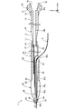
- FIG. 1 is an explanatory diagram illustrating the configuration of the catheter 1.
- a balloon catheter is exemplified as the catheter 1 .
- a balloon catheter 1 is used by being inserted into a blood vessel, and has a balloon that is expanded/contracted by the supply/discharge of fluid.
- the balloon catheter 1 can dilate a constriction or an obstruction in a blood vessel with the balloon to ensure blood flow.
- the balloon catheter 1 may be used by being inserted into biological lumens such as the lymphatic system, the biliary system, the urinary system, the respiratory system, the digestive system, the secretory glands, and the reproductive organs, in addition to the blood vessel system. .
- the balloon catheter 1 is also simply referred to as "catheter 1".
- the catheter 1 includes a first tube 10, a second tube 20, a balloon 30, an inner tube 40, a core wire 50, a distal tip 60, and a connector 70.
- the first tube 10 and the second tube 20 are also collectively called "shaft body". Since the first tube 10 and the second tube 20 have the configurations described later, the catheter 1 can suppress stress concentration at the connecting portion between the first tube 10 and the second tube 20 . Note that FIG. 1 shows a state in which the balloon 30 is deflated.
- FIG. 1 the axis of the catheter 1 that passes through the center of the first tube 10 is represented by the axis O (one-dot chain line).
- FIG. 1 includes a portion in which the relative size ratio of each component is described as different from the actual size. In addition, it includes a portion exaggeratedly describing a part of each constituent member.
- FIG. 1 illustrates XYZ axes that are orthogonal to each other.
- the X-axis corresponds to the longitudinal direction of the catheter 1
- the Y-axis corresponds to the height direction of the catheter 1
- the Z-axis corresponds to the width direction of the catheter 1 .
- distal side of the catheter 1 and each component
- proximal side of the catheter 1 and each component
- distal end one end located on the distal side
- base end one end located on the proximal side
- distal end and base end are referred to as the distal portion
- proximal end and the vicinity thereof are referred to as the “basal end portion”.
- the distal side is inserted into the living body, and the proximal side is operated by an operator such as a doctor.
- the distal tip 60 is a member that is arranged at the distal end portion 1d of the catheter 1 and advances through the blood vessel ahead of other members.
- the distal tip 60 has a hollow shape in which openings are formed at the distal end and the proximal end, respectively, and a lumen communicating between the openings is formed inside.
- the opening on the distal side of the distal tip 60 is also referred to as "the distal side opening 40a".
- the tip-side opening 40a is used for inserting and removing a medical device such as a guide wire into and out of the catheter 1 (specifically, a wire lumen 40L, which will be described later).
- the outer shape of the distal tip 60 is tapered from the proximal side to the distal side in order to facilitate the advancement of the catheter 1 in the living body lumen.
- the outer diameter and length of the distal tip 60 can be arbitrarily determined.
- the distal tip 60 preferably has flexibility, and can be made of a resin material such as polyurethane, polyurethane elastomer, or the like.
- the balloon 30 is a tube-shaped member that can be expanded and contracted in the radial direction (YZ-axis direction) of the catheter 1 and that has open ends on the distal end side and the proximal end side.
- the balloon 30 is deformed out-of-plane by supplying a fluid to the space 30L formed inside, and expands (diameter increases) radially outward.
- the balloon 30 undergoes in-plane deformation by discharging the fluid inside the space 30L, and shrinks (reduces in diameter) radially inward.
- the expansion pressure, outer diameter and length of balloon 30 can be determined arbitrarily.
- the balloon 30 may have a structure in which it is folded in a deflated state.
- the distal end portion 38 of the balloon 30 is fixed to the outer peripheral surface of the distal tip 60 .
- a proximal end portion 39 of the balloon 30 is fixed to the outer peripheral surface of the distal end portion 28 of the second tube 20 .
- the balloon 30 can be made of a material that can be expanded and contracted in response to changes in internal pressure, has flexibility that can suppress damage to the inside of the blood vessel, and has hardness that allows expansion within the lesion.
- the balloon 30 may be made of polyethylene, polypropylene, polyolefin such as ethylene-propylene copolymer, polyester such as polyethylene terephthalate, polyvinyl chloride, ethylene-vinyl acetate copolymer, cross-linked ethylene-vinyl acetate copolymer, polyurethane, or the like.
- thermoplastic resin polyamide elastomer, polyolefin elastomer, silicone rubber, latex rubber, or the like.
- the second tube 20 is an elongated member extending along the axis O.
- the second tube 20 has a hollow, substantially cylindrical shape with openings formed at the distal end and the proximal end, respectively, and a lumen (fluid lumen 20L) communicating between the openings inside.
- the second tube 20 has a large-diameter portion 21, a tapered portion 22, and a small-diameter portion 23 from the distal end side to the proximal end side.
- the large-diameter portion 21 has an outer diameter and an inner diameter that are larger than those of the small-diameter portion 23 .
- the tapered portion 22 is provided between the large-diameter portion 21 and the small-diameter portion 23, and is a portion in which the outer diameter and the inner diameter gradually decrease from the distal end side to the proximal end side.
- the small diameter portion 23 is provided at the proximal end portion of the second tube 20 .
- the side surface of the second tube 20 is formed with a port 40b, which is an opening communicating between the inside and outside of the cylinder.
- the port 40b is used to insert and withdraw a medical device such as a guide wire into and out of the catheter 1 (specifically, a wire lumen 40L, which will be described later).
- the outer diameter and length of the second tube 20, the position, size, shape, etc. of the port 40b can be arbitrarily determined. In the example of FIG. 1, the outer diameter and inner diameter of the second tube 20 on the distal side of the port 40b are different from the outer diameter and inner diameter of the second tube 20 on the proximal side of the port 40b. They may be
- a proximal end portion 39 of the balloon 30 is fixed to the outer peripheral surface of the distal end portion 28 of the second tube 20 .
- the first tube 10 is fixed to the inner peripheral surface of the small diameter portion 23 of the second tube 20 .
- the second tube 20 preferably has antithrombogenicity, flexibility, and biocompatibility, and is made of a resin material such as polyamide resin, polyolefin resin, polyester resin, polyurethane resin, silicone resin, or fluorine resin. there is That is, the second tube 20 is a resin tube.
- the inner tube 40 shown in FIG. 1 is an elongated member extending along the axis O and having a diameter smaller than that of the second tube 20 .
- the inner tube 40 has a hollow, substantially cylindrical shape with openings formed at the distal end and the proximal end, respectively, and a lumen (wire lumen 40L) communicating between the openings inside.
- the inner tube 40 has a body portion 41 and a curved portion 42 from the distal end side to the proximal end side.
- the body portion 41 is a portion that is arranged inside the balloon 30 and the second tube 20 and extends linearly along the axis O. As shown in FIG.
- the curved portion 42 is provided near the proximal end of the inner tube 40, and is a portion of the inner tube 40 curved in a direction away from the axis O (in other words, a direction in which the port 40b is located). be.
- a distal end portion 48 of the inner tube 40 is fixed to a distal tip 60 .
- the base end portion 49 of the inner tube 40 is fixed to the inner peripheral surface of the second tube 20 in a state in which the side opening (port 40b) of the second tube 20 communicates with the wire lumen 40L.
- the outer diameter and length of the inner tube 40 can be determined arbitrarily.
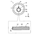
- FIG. 2 is an explanatory diagram illustrating a cross-sectional configuration taken along line AA of FIG.
- An example of the configuration of the inner tube 40 is shown in the broken-line balloon in the lower part of FIG.
- the inner tube 40 of this embodiment has a structure in which a coil body 402 is embedded inside a thick portion 401 .
- the coil body 402 is a single-filament coil formed by winding one wire into a single-filament.
- the coil body 402 may be a multi-strand coil formed by winding a plurality of strands in multiple strands, and may be formed by winding a single strand of a twisted wire obtained by twisting a plurality of strands.
- the thick portion 401 can be made of, for example, a resin material such as polyamide resin, polyolefin resin, polyester resin, polyurethane resin, silicone resin, or fluorine resin.
- the coil body 402 can be made of, for example, a metal material such as stainless steel such as SUS304, a nickel-titanium alloy, or a cobalt-chromium alloy.
- the core wire 50 is an elongated member extending along the axis O and having a smaller diameter than the second tube 20 and the inner tube 40 .
- the core wire 50 has a substantially cylindrical solid shape.
- a tapered portion having a gradually changing outer diameter may be provided between the distal end and the proximal end of the core wire 50 .
- the taper portion may have a configuration in which the outer diameter gradually decreases toward the distal end side.
- the core wire 50 is arranged inside the second tube 20 .
- the distal end of core wire 50 is not fixed to second tube 20 or inner tube 40 .
- a proximal end portion 59 of the core wire 50 is fixed to the inner peripheral surface of the distal end portion of the first tube 10 .
- the outer diameter and length of core wire 50 can be arbitrarily determined.
- the core wire 50 of this embodiment is made of a cobalt-chromium alloy.
- the core wire 50 may be made of a metal material other than the cobalt-chromium alloy, such as stainless steel such as SUS304, nickel-titanium alloy, or the like.
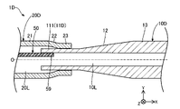
- FIG. 3 is an enlarged view of the connecting portion (FIG. 1: B portion) of the first tube 10 and the second tube 20.
- FIG. FIG. 4 is a cross-sectional view of the connecting portion of the first tube 10 and the second tube 20.
- FIG. 4A illustrates a cross-sectional configuration along line CC of FIG. 3
- FIG. 4B illustrates a cross-sectional configuration along line DD of FIG.
- a "second region 112" of the first tubular portion 11, which will be described later, is hatched to distinguish it from other portions.
- FIG. 1, 3 and 4. the configuration of the first tube 10 will be described with reference to FIGS. 1, 3 and 4.
- the first tube 10 is an elongated member extending along the axis O.
- the first tube 10 has a hollow, substantially cylindrical shape with openings formed at a distal end and a proximal end, respectively, and a lumen (fluid lumen 10L) communicating between the openings.
- the first tube 10 has a first tubular portion 11, a tapered portion 12, and a second tubular portion 13 from the distal side toward the proximal side.
- the first tubular portion 11 is a portion provided on the distal end side of the first tube 10 and having a first outer diameter ⁇ 11 ( FIG. 3 ).
- the second tubular portion 13 is a portion provided on the proximal end side of the first tube 10 and having a second outer diameter ⁇ 13 ( FIG.
- the tapered portion 12 is a portion provided between the first tubular portion 11 and the second tubular portion 13 .
- An outer diameter ⁇ 12 (FIG. 3) of the tapered portion 12 gradually increases from the distal end side to the proximal end side.
- the first tubular portion 11, the tapered portion 12, and the second tubular portion 13 each have the same inner diameter ⁇ 10.
- the terms “identical” and “equal” in this embodiment are not limited to the case of strict matching, but are meant to allow for differences due to manufacturing errors and the like. Further, in this embodiment, when the member (or lumen) has an elliptical cross section, the “outer diameter” and “inner diameter” refer to the length of the longest portion of any given cross section.
- the first tubular portion 11 of the first tube 10 has a first region 111, a second region 112, and a first region 113 from the distal side to the proximal side.
- the first region 111 , the second region 112 , and the first region 113 are regions distinguished by the difference in “surface roughness” of the outer peripheral surface of the first tubular portion 11 .
- Arithmetic mean roughness (Ra) is used in the present embodiment as a scale for defining surface roughness.
- the surface roughness of the second region 112 is greater than the surface roughness of the first region 111 and greater than the surface roughness of the first region 113 .
- the surface roughness of the first region 111 and the surface roughness of the first region 113 may be the same or different as long as they are both smaller than the surface roughness of the second region 112 . That is, in the first tube 10 of the present embodiment, the first regions 111 and 113 are provided on the outer peripheral surface of the first cylindrical portion 11 so as to be adjacent to the second region 112 at both ends of the second region 112 . It is
- FIGS. 5 and 6 are diagrams for explaining the surface roughness.
- FIG. 5A shows an example of an enlarged photograph of the first region 111.
- FIG. 5B shows an example of an enlarged photograph of the second area 112.
- the enlarged photograph shown in FIG. 5 is an image obtained by photographing the first region 111 and the second region 112 of the first tube 10 using a laser microscope.
- FIG. 6A shows an example of a measured cross-sectional curve of the first region 111.
- FIG. FIG. 6B shows an example of a measured cross-sectional curve of the second region 112.
- FIG. The measured cross-sectional curves shown in FIG. 6 are obtained by measuring the first region 111 and the second region 112 of the first tube 10 with a laser microscope.
- the horizontal axis plots the evaluation length ( ⁇ m), and the vertical axis plots the surface height ( ⁇ m) at each position.
- Ra was measured using a multi-line roughness meter (VK-250, manufactured by Keyence Corporation).
- the measurement length (lengthwise direction of the first tube 10) was 286 ⁇ m, and the cutoff value was set at 0.8 ⁇ m.
- the number of peripheral lines was set to 18, and the interval was set to 4 mm (the interval in the image taken at a magnification of 50).
- the surface (outer peripheral surface of the first tubular portion 11) is in a smooth state with little unevenness.
- the surface in the first region 111, there is no significant change in the height of the surface.
- Ra of the first region 111 obtained based on the measured cross-sectional curve shown in FIG. 6A was 0.19 ( ⁇ m).
- the surface in the enlarged photograph of the second region 112, the surface (the outer peripheral surface of the first cylindrical portion 11) has an uneven surface in which a plurality of substantially circular recesses HE are formed. is in a certain state. Further, as shown in FIG.
- the surface roughness of the second region 112 can be set within a range of 10 to 50 times the surface roughness of the first region 111 (and/or the surface roughness of the first region 113). can also be set within the range of By setting the surface roughness of the second region 112 within the above range, the surface roughness of the second region 112 is roughened to the extent that sufficient bonding strength with the second tube 20 is exhibited. Even so, it is possible to suppress the sudden decrease in the stiffness of the first tube 10 at the first cylindrical portion 11 (to achieve a smoother gradual change in stiffness).
- Such a first tube 10 can be produced, for example, as follows. First, a metal tube having a second outer diameter ⁇ 13 (FIG. 3) and an inner diameter ⁇ 10 (FIG. 3) is prepared. A portion of the tip of the tube is ground using a centerless machine to form the first tubular portion 11 and the tapered portion 12 . After that, the second region 112 (recess HE) is formed by performing laser processing on the surface of the substantially central portion of the first cylindrical portion 11 in the longitudinal direction.
- the first tube 10 is made of, for example, a metal material such as stainless steel such as SUS304, nickel-titanium alloy, or cobalt-chromium alloy. That is, the first tube 10 is a metal tube.
- the narrow diameter portion 23 (base end portion) of the second tube 20 described above is fixed to the outer peripheral surface of the first cylindrical portion 11 of the first tube 10. ing. Specifically, the small diameter portion 23 (base end portion) of the second tube 20 is fixed to the second region 112 of the outer peripheral surface of the first cylindrical portion 11 . In the illustrated example, the small diameter portion 23 is fixed only to the second region 112, but it is sufficient that the small diameter portion 23 is fixed to at least the second region 112, and in addition to the second region 112, It may also be fixed to a portion of the first region 111 or the first region 113 . As shown in FIGS.
- the base end portion 59 of the core wire 50 described above is fixed to the inner peripheral surface of the first tubular portion 11 of the first tube 10 .
- the base end portion 59 of the core wire 50 is fixed to a region of the inner peripheral surface of the first tubular portion 11 where the first region 111 is formed on the corresponding outer peripheral surface.
- the connector 70 is a member arranged at the proximal end portion 1p of the catheter 1 and held by the operator.
- the connector 70 has a hollow shape in which openings are formed at the distal end and the proximal end, respectively, and a lumen (fluid lumen 70L) communicating between the openings is formed inside.
- the connector 70 has two wing members 71 that are used when the operator grips the catheter 1 .
- the vane member 71 can be of any shape.
- the blade member 71 may be omitted.
- the connector 70 can be made of, for example, a resin material such as polyamide, polypropylene, polycarbonate, polyacetal, polyethersulfone.
- the base end portion 19 of the first tube 10 is fixed to the connector 70 while the fluid lumen 70L and the fluid lumen 10L are communicated with each other.
- the fluid lumen 70L of the connector 70, the fluid lumen 10L of the first tube 10, and the fluid lumen 20L of the second tube 20 are for supplying/discharging the fluid to/from the space 30L inside the balloon 30. function as a road.
- the above-mentioned members can be fixed together by any method.
- Adhesives such as adhesives
- welding can be used.
- FIG. 7 is a diagram explaining the catheter 1 at the time of delivery.
- Catheter 1 can be used, for example, as follows. First, the operator inserts the guidewire 2 into the patient's blood vessel and delivers the guidewire 2 to the stenosis or occlusion of the blood vessel. The operator inserts the base end of the guide wire 2 into the wire lumen 40L through the distal opening 40a and draws it out from the port 40b. After that, the operator delivers the catheter 1 along the guide wire 2 to the stenosis or occlusion of the blood vessel.
- the catheter 1 since the catheter 1 includes the inner tube 40 connected to the port 40b formed on the side surface of the second tube 20, the catheter 1 can be used as a so-called rapid exchange type catheter. 2 can be inserted quickly.
- FIG. 8 is a diagram explaining the catheter 1 when the balloon 30 is inflated.
- the operator After delivering the catheter 1 (specifically, the balloon 30) to the stenosis or occlusion of the blood vessel, the operator attaches a syringe or the like to the proximal end of the connector 70 to supply fluid. Fluid fills the space 30L inside the balloon 30 through the fluid lumens 70L, 10L, 20L.
- the balloon 30 is deformed out-of-plane and expands radially outward, thereby dilating the stenosed part or the obstructed part.
- the balloon 30 is expanded with the guide wire 2 removed, but the balloon 30 may be expanded while the guide wire 2 is inserted through the wire lumen 40L.
- the metal first tube 10 includes the first tubular portion 11 having a first outer diameter provided on the distal side and the first cylindrical portion 11 provided on the proximal side. and a second tubular portion 13 having a second outer diameter larger than the provided first outer diameter (FIGS. 1 and 3). Therefore, the distal end side of the first tube 10 can be made more flexible than the proximal end side, and safety can be improved.
- the metal first tube 10 also has a tapered portion 12 provided between the first tubular portion 11 and the second tubular portion 13 (FIGS. 1 and 3).
- the rigidity of the first tube 10 can be gradually changed, and the stress concentration caused by the sudden change in rigidity can be reduced. can be suppressed.
- the base end portion (small diameter portion 23) of the second resin tube 20 is fixed to the outer peripheral surface of the first tubular portion 11 having the smallest outer diameter among the first metal tubes 10. (Fig. 3). Therefore, compared to the case where the second tube 20 is fixed to the second tubular portion 13, the rigidity of the shaft body (that is, the first tube 10 and the second tube 20) can be gradually changed, and the rigidity can be improved. Stress concentration due to sudden changes can be suppressed.
- a first cylindrical portion 11 is provided separately from the tapered portion 12 provided for gradual rigidity change. is fixed, compared to the case where the base end portion (small diameter portion 23) is fixed to the tapered portion 12 (inclined surface), a stable and high bonding strength between the first tube 10 and the second tube 20 can be obtained. .
- the bonding strength of metal-resin bonding is lower than that of metal-to-metal bonding or resin-to-resin bonding.
- the outer peripheral surface of the first tubular portion 11 of the first tube 10 has the second region 112 having relatively larger surface roughness than the first regions 111 and 113.
- the base end portion (small diameter portion 23) of the second tube 20 is fixed to at least the second region 112 of the outer peripheral surface of the first tubular portion 11 (FIG. 3).
- first cylindrical portion 11 separately from the tapered portion 12 provided for the gradual rigidity change, and providing the second region 112 having a large surface roughness on the outer peripheral surface of the first cylindrical portion 11,
- the surface roughness of the second region 112 can be stabilized compared to the case where the tapered portion 12 (inclined surface) is provided with a region having a large surface roughness, and the first tube 10 and the second tube 20 can be sufficiently separated from each other. Stable high bonding strength can be obtained.
- the second region 112 has a larger surface roughness than the first regions 111 and 113 (FIGS. 5 and 6). Therefore, in the first tubular portion 11, the rigidity of the portion where the second region 112 is provided is lower than the rigidity of the portions where the first regions 111 and 113 are provided. In this respect, according to the catheter 1 of the first embodiment, since the first regions 111 and 113 are provided on both sides of the second region 112, the first tubular portion 11 is provided with the first region 113. It is connected to the tapered portion 12 through the tapered portion (FIG. 3).
- the rigidity of the first tube 10 can be gradually changed, and the stress concentration caused by the sudden change in rigidity can be reduced. can be suppressed. As a result, breakage of the first tube 10 due to stress concentration can be suppressed.
- the catheter 1 includes the core wire 50 arranged inside the second tube 20 and having the proximal end 59 fixed to the distal end of the first tube 10 (Fig. 1 , Fig. 3). Therefore, the rapid change in stiffness between the first tube 10 and the second tube 20 can be further mitigated. As a result, breakage of the first tube 10 and the second tube 20 due to stress concentration can be further suppressed. Also, the base end portion 59 of the core wire 50 is fixed to a region of the inner peripheral surface of the first cylindrical portion 11 where the first region 111 is formed on the corresponding outer peripheral surface (FIG. 3). Therefore, the outer diameter of the catheter 1 can be reduced.
- the core wire 50 is made of a cobalt-chromium alloy, abrupt changes in rigidity between the first tube 10 and the second tube 20 can be more effectively prevented than when a stainless steel alloy such as SUS304 is used. can be alleviated further. As a result, breakage of the first tube 10 and the second tube 20 due to stress concentration can be further suppressed.
- the first tube 10 has the same inner diameter at the distal end and the inner diameter at the proximal end ( FIG. 3 : ⁇ 10). In other words, it is not necessary to reduce the inner diameter of the first tube 10 in order to gradually change the rigidity of the first tube 10 . Therefore, for example, when the balloon 30 is provided on the distal end side of the second tube 20 and the catheter 1 is configured as a balloon catheter (cases such as those shown in FIGS. 1 and 8), the inner diameter of the first tube 10 is equal to the outer diameter.
- Fluid can be supplied/exhausted at a sufficient flow rate through the fluid lumen 10L of the first tube 10 compared to the case where the in/deflation time of the balloon 30 (the balloon 30 expands/deflates) time required for contraction) can be shortened.
- FIG. 9 is an enlarged view of the connecting portion of the first tube 10A and the second tube 20 of the catheter 1A of the second embodiment.
- 2nd Embodiment demonstrates the example from which the structure of 11 A of 1st cylindrical parts differs.
- a catheter 1A of the second embodiment includes a first tube 10A instead of the first tube 10 in the configuration described in the first embodiment.
- the first tube 10A has a first tubular portion 11A instead of the first tubular portion 11.
- the first cylindrical portion 11A has a first region 111 and a second region 112 from the distal end side to the proximal end side, and does not have the first region 113 described in the first embodiment. do not have.
- the first region 111 is located on the tip side of the second region 112 and is adjacent to the second region 112 .
- the configuration of the first tubular portion 11A can be modified in various ways. good too.
- Such a second embodiment can also provide the same effects as the first embodiment described above.
- the first region 111 is located on the distal side of the second region 112 to which the proximal end portion 59 of the second tube 20 is fixed.
- another member for example, the core wire 50 in FIG. 9 arranged inside the second tube 20 is placed on the corresponding outer peripheral surface of the inner or outer peripheral surface of the first tubular portion 11A. It can be attached to the area where the area 111 is formed.
- FIG. 10 is an enlarged view of the connecting portion of the first tube 10B and the second tube 20B of the catheter 1B of the third embodiment.
- 3rd Embodiment demonstrates the example from which the structure of the 1st cylindrical part 11B differs.
- the catheter 1B of the third embodiment has the configuration described in the first embodiment, with a first tube 10B instead of the first tube 10, a second tube 20B instead of the second tube 20, and a core wire 50 A core wire 50B is provided instead.
- the first tube 10B has a first tubular portion 11B instead of the first tubular portion 11.
- the first tubular portion 11B has a second region 112 and a first region 113 from the distal end side to the proximal end side, and does not have the first region 111 described in the first embodiment. do not have.
- the second region 112 is located on the tip side of the first region 113 and adjacent to the first region 113 .
- the second tube 20B has a small diameter portion 23 (base end portion) fixed to the first region 113 of the outer peripheral surface of the first tubular portion 11B.
- the base end portion 59 of the core wire 50B is fixed to a region of the inner peripheral surface of the first cylindrical portion 11B where the second region 112 is formed on the corresponding outer peripheral surface.
- the configuration of the catheter 1B can be modified in various ways. It may be fixed. Also, the core wire 50B may be fixed to a region of the first tubular portion 11B where the second region 112 is formed on the corresponding outer peripheral surface.
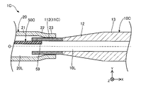
- FIG. 11 is an enlarged view of the connecting portion of the first tube 10C and the second tube 20 of the catheter 1C of the fourth embodiment.
- 4th Embodiment demonstrates the example from which the structure of 11 C of 1st cylindrical parts differs.
- a catheter 1C of the fourth embodiment includes a first tube 10C instead of the first tube 10 and a core wire 50C instead of the core wire 50 in the configuration described in the first embodiment.
- the first tube 10C has a first tubular portion 11C instead of the first tubular portion 11.
- the first tubular portion 11C is entirely the second region 112 and does not have the first regions 111 and 113 described in the first embodiment.
- the second region 112 is a region distinguished from the tapered portion 12 by a difference in “surface roughness”. Specifically, in the fourth embodiment, the surface roughness of the second region 112 is greater than the surface roughness of the tapered portion 12 .
- the base end portion 59 of the core wire 50C is fixed to a region of the inner peripheral surface of the first cylindrical portion 11C where the second region 112 is formed on the corresponding outer peripheral surface.
- the configuration of the catheter 1C can be modified in various ways.
- the entire first tubular portion 11C may be the second region 112 having a surface roughness greater than that of the tapered portion 12.
- the core wire 50C may be fixed at an arbitrary position on the inner peripheral surface of the first tubular portion 11C.
- Such a fourth embodiment can also achieve the same effects as the above-described first embodiment.
- the second region 112 having a large surface roughness is provided over the entire first cylindrical portion 11C, which can be distinguished at a glance because of its small outer diameter. Therefore, the work for fixing the second tube 20C to the first tube 10C can be simplified.
- FIG. 12 is an enlarged view of the connecting portion of the first tube 10D and the second tube 20D of the catheter 1D of the fifth embodiment.
- 5th Embodiment demonstrates the example from which the structure of 1st cylindrical part 11D differs.
- a catheter 1D of the fifth embodiment has a first tube 10D instead of the first tube 10 and a second tube 20D instead of the second tube 20 in the configuration described in the first embodiment.
- the first tube 10D has a first tubular portion 11D instead of the first tubular portion 11.
- the first tubular portion 11D is entirely the first region 111 and does not have the second region 112 and the first region 113 described in the first embodiment.
- the surface roughness of the first region 111 of the first tubular portion 11D may be the same as or different from the surface roughness of the tapered portion 12 .
- the second tube 20D has a small diameter portion 23 (base end portion) fixed to the first region 111 of the outer peripheral surface of the first tubular portion 11D.
- the configuration of the catheter 1D can be modified in various ways.
- the first cylindrical portion 11D does not have the second region 112 with relatively large surface roughness, and the entire first tubular portion 11D It may be area 111 .
- the second tube 20D does not have to have the small diameter portion 23 (base end portion) fixed to the second region 112 having a relatively large surface roughness.
- the same effects as those of the above-described first embodiment can also be obtained by such a fifth embodiment.
- the work for fixing the second tube 20D to the first tube 10D can be simplified.
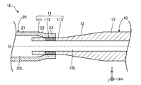
- FIG. 13 is an enlarged view of the connecting portion of the first tube 10 and the second tube 20 of the catheter 1E of the sixth embodiment.
- the catheter 1E of the sixth embodiment does not have the core wire 50 in the configuration described in the first embodiment.
- the configuration of the catheter 1E can be modified in various ways, and may be configured without the core wire 50 as shown in FIG. Alternatively, the configuration may be such that the distal tip 60 described with reference to FIG. 1 is not provided. When the distal tip 60 is omitted, the distal end portion 38 of the balloon 30 may be fixed to the distal end portion of the inner tube 40 .
- Such a sixth embodiment can also achieve the same effect as the above-described first embodiment. Further, according to the catheter 1E of the sixth embodiment, the cost of the catheter 1E can be reduced by omitting some of the constituent members.
- FIG. 14 is an enlarged view of the connecting portion of the first tube 10F and the second tube 20 of the catheter 1F of the seventh embodiment.
- a catheter 1F of the seventh embodiment includes a first tube 10F instead of the first tube 10 in the configuration described in the first embodiment.
- the first tube 10F has a first tubular portion 11, a tapered portion 12F, and a second tubular portion 13F from the distal end side to the proximal end side.
- the configuration of the first tubular portion 11 is the same as that of the first embodiment.
- the second tubular portion 13F is a portion provided on the proximal end side of the first tube 10F.
- the second tubular portion 13F has a second outer diameter ⁇ 13 larger than the first outer diameter ⁇ 11 of the first tubular portion 11 and an inner diameter ⁇ 130 larger than the inner diameter ⁇ 10 of the first tubular portion 11. is doing.
- the tapered portion 12F is a portion provided between the first tubular portion 11 and the second tubular portion 13F.
- An outer diameter ⁇ 12 of the tapered portion 12F gradually increases from the distal end side toward the proximal end side.
- the inner diameter ⁇ 120 of the tapered portion 12F gradually increases from the distal end side to the proximal end side.
- the "outer diameter” and “inner diameter” refer to the length of the longest portion of any cross section when the cross section of the member (or lumen) is elliptical.
- the configuration of the catheter 1F can be modified in various ways.
- the first tube 10F does not have a substantially constant inner diameter ⁇ 10, and the inner diameter varies as well as the outer diameter. good too.
- the same effects as those of the above-described first embodiment can be obtained.
- the catheter 1F of the seventh embodiment since the inner diameter of the fluid lumen 10L can be expanded inside the tapered portion 12F of the first tube 10F and inside the second cylindrical portion 13F, another member is arranged inside. space can be provided for
- FIG. 15 is an explanatory diagram illustrating the configuration of the catheter 1G of the eighth embodiment.
- the catheter 1G of the eighth embodiment includes a second tube 20G instead of the second tube 20, an inner tube 40G instead of the inner tube 40, and an inner tube 40G instead of the connector 70.
- a connector 70G is provided.
- the second tube 20G does not have the side opening (port 40b) described in the first embodiment.
- the inner tube 40G does not have the curved portion 42 described in the first embodiment, and is linearly curved along the axis O inside the balloon 30, the second tube 20G, the first tube 10, and the connector 70G. extended.
- a distal end portion 48 of the inner tube 40G is fixed to a distal tip 60 .
- a proximal end portion 49 of the inner tube 40G is fixed to the connector 70 by a sealing member 77, which will be described later.
- the connector 70G has a branch portion 72, a first branch 73, a second branch 74, a first blade portion 75, a second blade portion 76, and a sealing member 77.
- the branching part 72 is a member configured by two tubular bodies that are connected in a state that the lumens are communicated.
- a branch extending in the X-axis direction is called a first branch 73
- a branch extending in the XY directions is called a second branch 74 .
- a proximal end portion 49 of the inner tube 40G and a sealing member 77 for fixing the proximal end portion 49 of the inner tube 40G to the inner peripheral surface of the first branch 73 are provided in the lumen 73L of the first branch 73. , are placed.
- a first blade portion 75 that is used by the operator to grip the first branch 73 is fixed to the proximal end portion of the first branch 73 .
- the operator can put the guide wire in and out of the inner tube 40 ⁇ /b>G through the opening 1 c provided at the proximal end of the first blade portion 75 .
- a second blade portion 76 that is used by the operator to grip the second branch 74 is fixed to the proximal end portion of the second branch 74 .
- the operator can supply fluid for expanding the balloon 30 to the fluid lumens 10L, 20L, and 74L by attaching a syringe or the like to the opening 1d provided at the proximal end of the second vane portion 76.
- the branch portion 72, the first branch 73, the second branch 74, the first blade portion 75, the second blade portion 76, and the sealing member 77 can be made of any resin material.
- the configuration of the catheter 1G can be changed in various ways, and the catheter 1G may be configured as an over-the-wire type catheter.
- Such an eighth embodiment can also achieve the same effect as the above-described first embodiment.
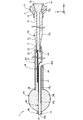
- FIG. 16 is an explanatory diagram illustrating the configuration of the catheter 1H of the ninth embodiment.
- a catheter 1H of the ninth embodiment includes a balloon 30H instead of the balloon 30 in the configuration described in the first embodiment.
- the balloon 30 ⁇ /b>H has a distal end portion 38 fixed to the outer peripheral surface of the inner tube 40 .
- FIG. 17 is an explanatory diagram illustrating the configuration of the catheter 1I of the tenth embodiment.
- the catheter 1I has the second tube 20I instead of the second tube 20 and does not have the balloon 30 in the configuration described in the first embodiment.
- the second tube 20I has a small diameter portion 25, a tapered portion 26, a large diameter portion 21, a tapered portion 22, and a small diameter portion 23 from the distal end side to the proximal end side.
- the small-diameter portion 25 is provided on the most distal side of the second tube 20I, and has a smaller outer diameter and smaller inner diameter than the large-diameter portion 21 .
- the tapered portion 26 is provided between the small-diameter portion 25 and the large-diameter portion 21, and is a portion where the outer diameter and the inner diameter gradually change greatly from the distal end side to the proximal end side.
- the large-diameter portion 21, the tapered portion 22, and the small-diameter portion 23 are as described in the first embodiment.
- the small diameter portion 23 (tip portion) of the second tube 20I is fixed to the outer peripheral surface of the tip 60 .
- the configuration of the catheter 1I can be modified in various ways, and may be configured as a catheter without the balloon 30.
- the example of FIG. 17 illustrates the case where the catheter 1I is a rapid exchange catheter.
- catheter 1I may also be an over-the-wire catheter.
- the inner tube 40G described with reference to FIG. 15 may be adopted.
- the bifurcated connector 70G is not required because a fluid supply port is not required.
- Such a tenth embodiment can also achieve the same effect as the above-described first embodiment.
- each member included in the catheter 1 has at least one of the inner peripheral surface and the outer peripheral surface to improve any one of antithrombogenicity, biocompatibility, lubricity, abrasion resistance, and sliding property. coating may be applied.
- the second tube 20 may be configured by combining a plurality of tubes.
- the port 40b may be formed by using two tubes having different outer diameters and inner diameters and shifting the joints of the two tubes.
- the catheter 1 may have other configurations not described above.
- a radiopaque marker portion provided on the outer peripheral surface of the inner tube 40 inside the balloon 30 can be exemplified.
- a wire lumen 40L, a second inner tube for forming a separate lumen different from the fluid lumens 10L, 20L, 70L, and the like can be exemplified.
- the coil body 402 may not be embedded in the inner tube 40 .
- core wire 50 may be fixed to the outer peripheral surface of first tube 10 .
- the core wire 50 may be configured to have a substantially constant outer diameter from the distal end to the proximal end (in other words, a configuration without the small diameter portion 52).
- the configurations of the first tubular portions 11A to 11D described in any of the second to fifth embodiments may be adopted.
- the configuration of the first cylindrical portions 11A-D described in any one of the second to fifth embodiments may be employed.
Landscapes
- Health & Medical Sciences (AREA)
- Life Sciences & Earth Sciences (AREA)
- Biophysics (AREA)
- Pulmonology (AREA)
- Engineering & Computer Science (AREA)
- Anesthesiology (AREA)
- Biomedical Technology (AREA)
- Heart & Thoracic Surgery (AREA)
- Hematology (AREA)
- Animal Behavior & Ethology (AREA)
- General Health & Medical Sciences (AREA)
- Public Health (AREA)
- Veterinary Medicine (AREA)
- Media Introduction/Drainage Providing Device (AREA)
Abstract
カテーテルは、金属材料により形成された第1チューブと、第1チューブの先端側に接続され、樹脂材料により形成された第2チューブとを備えている。第1チューブは、第1チューブの先端側に設けられ、第1の外径を有する第1筒状部と、第1チューブの基端側に設けられ、第1の外径よりも大きな第2の外径を有する第2筒状部と、第1筒状部と第2筒状部の間に設けられたテーパ部とを有し、第2チューブの基端部は、第1チューブのうち、第1筒状部の外周面に固定されている。
Description
本発明は、カテーテルに関する。
血管内に生じた狭窄部や閉塞部を拡張して、血流を確保するために用いられるバルーンカテーテルが知られている。例えば、特許文献1には、シャフト本体の先端部近傍の外周部に、周方向に拡張可能なバルーンが配置されたバルーンカテーテルが開示されている。
ところで、特許文献1に記載のバルーンカテーテルにおいて、プッシャビリティ(押し込み力)を向上させつつ安全性を向上させるために、シャフト本体を複数のチューブにより構成する場合がある。例えば、シャフト本体について、プッシャビリティ向上のために、術者の手元に近い基端側に金属製チューブを配置し、安全性向上のために、体内に挿入される先端側に樹脂製チューブを配置した構成とする。しかし、このような場合、金属製チューブと樹脂製チューブとの剛性差が大きいことに起因して、2本のチューブの接続部分において、剛性の急激な変化による応力集中が生じるという課題があった。
なお、このような課題は、バルーンを有するバルーンカテーテルに限らず、カテーテルの全般に共通する。また、このような課題は、血管系に限らず、リンパ腺系、胆道系、尿路系、気道系、消化器官系、分泌腺及び生殖器官といった、生体管腔内に挿入されるカテーテルの全般に共通する。
本発明は、上述の課題の少なくとも一部を解決するためになされたものであり、シャフト本体を材料が異なる複数のチューブにより構成する場合において、チューブの接続部分における応力集中を抑制することを目的とする。
本発明は、上述の課題の少なくとも一部を解決するためになされたものであり、以下の形態として実現することが可能である。
(1)本発明の一形態によれば、カテーテルが提供される。このカテーテルは、金属材料により形成された第1チューブと、前記第1チューブの先端側に接続され、樹脂材料により形成された第2チューブと、を備え、前記第1チューブは、前記第1チューブの先端側に設けられ、第1の外径を有する第1筒状部と、前記第1チューブの基端側に設けられ、前記第1の外径よりも大きな第2の外径を有する第2筒状部と、前記第1筒状部と前記第2筒状部の間に設けられたテーパ部と、を有し、前記第2チューブの基端部は、前記第1チューブのうち、前記第1筒状部の外周面に固定されている。
この構成によれば、金属製の第1チューブは、先端側に設けられた第1の外径を有する第1筒状部と、基端側に設けられた第1の外径よりも大きな第2の外径を有する第2筒状部とを有しているため、第1チューブの先端側を基端側よりも柔軟にでき、安全性を向上できる。また、金属製の第1チューブは、第1筒状部と第2筒状部の間に設けられたテーパ部を有しているため、第1筒状部と第2筒状部とを直接接続する場合と比較して、第1チューブの剛性を徐変させることができ、剛性の急激な変化による応力集中を抑制できる。さらに、樹脂製の第2チューブの基端部は、金属製の第1チューブのうち、外径が最も小さい第1筒状部の外周面に固定されているため、第2チューブを第2筒状部に固定する場合と比較して、シャフト本体(すなわち、第1チューブ及び第2チューブ)の剛性を徐変させることができ、剛性の急激な変化による応力集中を抑制できる。この結果、シャフト本体を材料が異なる複数のチューブにより構成したカテーテルにおいて、チューブの接続部分における応力集中を抑制でき、応力集中によるシャフト本体の破損を抑制できる。また、剛性徐変のために設けたテーパ部とは別に第1筒状部を設け、この第1筒状部の外周面に第2チューブの基端部を固定するため、テーパ部(傾斜面)に基端部を固定する場合と比較して、第1チューブと第2チューブとの安定した高い接合強度が得られる。
(2)上記形態のカテーテルにおいて、前記第1筒状部の外周面は、第1領域と、前記第1領域よりも表面粗さが大きい第2領域と、を有しており、前記第2チューブの基端部は、前記第1筒状部の外周面のうち、少なくとも前記第2領域に固定されていてもよい。
例えば、金属同士の接合や樹脂同士の接合と比較して、金属と樹脂との接合は接合強度が低下することが知られている。この構成によれば、第1チューブの第1筒状部の外周面は、第1領域よりも表面粗さが相対的に大きい第2領域を有しており、第2チューブの基端部は、第1筒状部の外周面のうち、少なくとも第2領域に固定されている。このため、本構成のように、樹脂製の第2チューブが、金属製かつ相対的に細径の第1筒状部に接合(固定)される場合であっても、第1チューブと第2チューブとの接合強度の低下を抑制できる。この結果、シャフト本体を材料が異なる複数のチューブにより構成したカテーテルにおいて、耐圧強度の低下を抑制できる。また、剛性徐変のために設けたテーパ部とは別に第1筒状部を設け、この第1筒状部の外周面に表面粗さが大きい第2領域を設けることにより、テーパ部(傾斜面)に表面粗さが大きい領域を設ける場合と比較して、第2領域の表面粗さを安定させることができ、第1チューブと第2チューブとの十分に安定した高い接合強度が得られる。
例えば、金属同士の接合や樹脂同士の接合と比較して、金属と樹脂との接合は接合強度が低下することが知られている。この構成によれば、第1チューブの第1筒状部の外周面は、第1領域よりも表面粗さが相対的に大きい第2領域を有しており、第2チューブの基端部は、第1筒状部の外周面のうち、少なくとも第2領域に固定されている。このため、本構成のように、樹脂製の第2チューブが、金属製かつ相対的に細径の第1筒状部に接合(固定)される場合であっても、第1チューブと第2チューブとの接合強度の低下を抑制できる。この結果、シャフト本体を材料が異なる複数のチューブにより構成したカテーテルにおいて、耐圧強度の低下を抑制できる。また、剛性徐変のために設けたテーパ部とは別に第1筒状部を設け、この第1筒状部の外周面に表面粗さが大きい第2領域を設けることにより、テーパ部(傾斜面)に表面粗さが大きい領域を設ける場合と比較して、第2領域の表面粗さを安定させることができ、第1チューブと第2チューブとの十分に安定した高い接合強度が得られる。
(3)上記形態のカテーテルにおいて、前記第1筒状部の外周面において、前記第1領域は、前記第2領域よりも先端側に位置し、かつ、前記第2領域に隣接していてもよい。
この構成によれば、第1領域は、第2チューブの基端部が固定される第2領域よりも先端側に位置している。このため、第2チューブの内側に配置された他の部材を、第1筒状部の内周面または外周面のうち、対応する外周面に第1領域が形成された領域に対して取り付けることができる。
この構成によれば、第1領域は、第2チューブの基端部が固定される第2領域よりも先端側に位置している。このため、第2チューブの内側に配置された他の部材を、第1筒状部の内周面または外周面のうち、対応する外周面に第1領域が形成された領域に対して取り付けることができる。
(4)上記形態のカテーテルにおいて、前記第1筒状部の外周面において、前記第1領域は、前記第2領域の両側において、それぞれ前記第2領域に隣接して設けられていてもよい。
第2領域は、第1領域よりも表面粗さが大きいため、第1筒状部において、第2領域が設けられた部分の剛性は、第1領域が設けられた部分の剛性よりも低くなる。この構成によれば、第1領域は、第2領域の両側に設けられているため、第1筒状部は、第1領域が設けられた部分を介してテーパ部と接続する。このため、第2領域が設けられた部分を介してテーパ部と接続する場合と比較して、第1チューブの剛性を徐変させることができ、剛性の急激な変化による応力集中を抑制できる。この結果、応力集中による第1チューブの破損を抑制できる。
第2領域は、第1領域よりも表面粗さが大きいため、第1筒状部において、第2領域が設けられた部分の剛性は、第1領域が設けられた部分の剛性よりも低くなる。この構成によれば、第1領域は、第2領域の両側に設けられているため、第1筒状部は、第1領域が設けられた部分を介してテーパ部と接続する。このため、第2領域が設けられた部分を介してテーパ部と接続する場合と比較して、第1チューブの剛性を徐変させることができ、剛性の急激な変化による応力集中を抑制できる。この結果、応力集中による第1チューブの破損を抑制できる。
(5)上記形態のカテーテルでは、さらに、前記第2チューブの内側に配置され、基端部が前記第1チューブの先端部に固定されたコアワイヤを備えていてもよい。
この構成によれば、カテーテルは、第2チューブの内側に配置され、基端部が第1チューブの先端部に固定されたコアワイヤを備えるため、第1チューブと第2チューブの間の剛性の急激な変化をより一層緩和できる。この結果、応力集中による第1チューブ及び第2チューブの破損をより一層抑制できる。
この構成によれば、カテーテルは、第2チューブの内側に配置され、基端部が第1チューブの先端部に固定されたコアワイヤを備えるため、第1チューブと第2チューブの間の剛性の急激な変化をより一層緩和できる。この結果、応力集中による第1チューブ及び第2チューブの破損をより一層抑制できる。
(6)上記形態のカテーテルにおいて、前記コアワイヤの基端部は、前記第1筒状部の内周面のうち、対応する外周面に前記第1領域が形成された領域に固定されていてもよい。
この構成によれば、コアワイヤの基端部は、第1筒状部の内周面のうち、対応する外周面に第1領域が形成された領域に固定されているため、カテーテルの外径を小さくできる。
この構成によれば、コアワイヤの基端部は、第1筒状部の内周面のうち、対応する外周面に第1領域が形成された領域に固定されているため、カテーテルの外径を小さくできる。
(7)上記形態のカテーテルにおいて、前記コアワイヤは、コバルトクロム合金により形成されていてもよい。
この構成によれば、コアワイヤは、コバルトクロム合金により形成されているため、例えばSUS304等のステンレス合金等を用いる場合と比較して、第1チューブと第2チューブの間の剛性の急激な変化をより一層緩和できる。この結果、応力集中による第1チューブ及び第2チューブの破損をより一層抑制できる。
この構成によれば、コアワイヤは、コバルトクロム合金により形成されているため、例えばSUS304等のステンレス合金等を用いる場合と比較して、第1チューブと第2チューブの間の剛性の急激な変化をより一層緩和できる。この結果、応力集中による第1チューブ及び第2チューブの破損をより一層抑制できる。
(8)上記形態のカテーテルにおいて、前記第1チューブは、先端部の内径と基端部の内径とがそれぞれ等しくてもよい。
この構成によれば、第1チューブは、先端部の内径と基端部の内径とがそれぞれ等しい。換言すると、第1チューブの剛性を徐変するために、第1チューブの内径を小さくする必要がない。このため、例えば、第2チューブの先端側にバルーンを設けて、カテーテルをバルーンカテーテルとして構成した場合に、第1チューブの内径が外径にあわせて変化する場合と比較して、第1チューブの流体ルーメンを介して十分な流量で流体を供給/排出することができ、バルーンのイン/デフレーションタイム(バルーンが拡張/収縮するまでに要する時間)を短くできる。
この構成によれば、第1チューブは、先端部の内径と基端部の内径とがそれぞれ等しい。換言すると、第1チューブの剛性を徐変するために、第1チューブの内径を小さくする必要がない。このため、例えば、第2チューブの先端側にバルーンを設けて、カテーテルをバルーンカテーテルとして構成した場合に、第1チューブの内径が外径にあわせて変化する場合と比較して、第1チューブの流体ルーメンを介して十分な流量で流体を供給/排出することができ、バルーンのイン/デフレーションタイム(バルーンが拡張/収縮するまでに要する時間)を短くできる。
(9)上記形態のカテーテルでは、さらに、前記第2チューブの先端側に配置された、拡縮可能なバルーンと、前記バルーン及び前記第2チューブの内側に配置されたインナーチューブと、前記インナーチューブの先端部に設けられた先端チップと、を備え、前記バルーンの先端部は、前記先端チップまたは前記インナーチューブの外周面に固定され、前記バルーンの基端部は、前記第2チューブの先端部に固定されていてもよい。
この構成によれば、カテーテルをバルーンカテーテルとして構成できる。
この構成によれば、カテーテルをバルーンカテーテルとして構成できる。
なお、本発明は、種々の態様で実現することが可能であり、例えば、カテーテル、バルーンカテーテル、カテーテル用のシャフト本体、及びこれらの製造方法などの形態で実現することができる。
<第1実施形態>
図1は、カテーテル1の構成を例示した説明図である。本実施形態では、カテーテル1として、バルーンカテーテルを例示する。バルーンカテーテル1は、血管内に挿入して使用され、流体の供給/排出によって拡張/収縮するバルーンを備えている。バルーンカテーテル1は、このバルーンによって、血管内に生じた狭窄部や閉塞部を拡張して、血流を確保することができる。なお、バルーンカテーテル1は、血管系のほか、リンパ腺系、胆道系、尿路系、気道系、消化器官系、分泌腺及び生殖器官といった、生体管腔内に挿入して使用されてもよい。以降、バルーンカテーテル1を、単に「カテーテル1」とも呼ぶ。
図1は、カテーテル1の構成を例示した説明図である。本実施形態では、カテーテル1として、バルーンカテーテルを例示する。バルーンカテーテル1は、血管内に挿入して使用され、流体の供給/排出によって拡張/収縮するバルーンを備えている。バルーンカテーテル1は、このバルーンによって、血管内に生じた狭窄部や閉塞部を拡張して、血流を確保することができる。なお、バルーンカテーテル1は、血管系のほか、リンパ腺系、胆道系、尿路系、気道系、消化器官系、分泌腺及び生殖器官といった、生体管腔内に挿入して使用されてもよい。以降、バルーンカテーテル1を、単に「カテーテル1」とも呼ぶ。
カテーテル1は、第1チューブ10と、第2チューブ20と、バルーン30と、インナーチューブ40と、コアワイヤ50と、先端チップ60と、コネクタ70と、を備えている。第1チューブ10と第2チューブ20を総称して「シャフト本体」とも呼ぶ。カテーテル1は、第1チューブ10及び第2チューブ20が後述する構成を有することにより、第1チューブ10と第2チューブ20との接続部分における応力集中を抑制できる。なお、図1では、バルーン30が収縮した状態を表す。
図1では、カテーテル1のうち、第1チューブ10の中心を通る軸を軸線O(一点鎖線)で表す。図1では、説明の便宜上、各構成部材の大きさの相対比を実際とは異なるように記載している部分を含んでいる。また、各構成部材の一部を誇張して記載している部分を含んでいる。また、図1には、相互に直交するXYZ軸を図示する。X軸はカテーテル1の長手方向に対応し、Y軸はカテーテル1の高さ方向に対応し、Z軸はカテーテル1の幅方向に対応する。図1の左側(-X軸方向)をカテーテル1及び各構成部材の「先端側」と呼び、図1の右側(+X軸方向)をカテーテル1及び各構成部材の「基端側」と呼ぶ。また、カテーテル1及び各構成部材の長手方向(X軸方向)における両端のうち、先端側に位置する一端を「先端」と呼び、基端側に位置する他端を「基端」と呼ぶ。また、先端及びその近傍を「先端部」と呼び、基端及びその近傍を「基端部」と呼ぶ。先端側は生体内部へ挿入され、基端側は医師等の術者により操作される。これらの点は、図1以降においても共通する。
先端チップ60は、カテーテル1の先端部1dに配置されて、他の部材よりも先行して血管内を進行する部材である。先端チップ60は、先端と基端にそれぞれ開口が形成され、内側に両開口を連通する内腔が形成された中空状である。先端チップ60の先端側の開口を「先端側開口40a」とも呼ぶ。先端側開口40aは、カテーテル1の内部(具体的には、後述するワイヤルーメン40L)に対してガイドワイヤ等の医療デバイスを出し入れするために用いられる。先端チップ60の外側形状は、カテーテル1の生体管腔内での進行をスムーズにするために、基端側から先端側にかけて縮径している。先端チップ60の外径及び長さは任意に決定できる。先端チップ60は、柔軟性を有することが好ましく、例えば、ポリウレタン、ポリウレタンエラストマー等の樹脂材料により形成できる。
バルーン30は、カテーテル1の径方向(YZ軸方向)に拡縮可能であり、かつ、先端側と基端側の両端部が開放したチューブ状の部材である。バルーン30は、内側に形成された空間30Lに流体を供給することによって面外変形して、径方向の外側へ拡張(拡径)する。また、バルーン30は、空間30Lの内部の流体を排出することによって面内変形して、径方向の内側へ収縮(縮径)する。このように、バルーン30は、流体の供給/排出によって、自在に拡張/収縮することができる。バルーン30の拡張圧、外径及び長さは任意に決定できる。なお、バルーン30は、収縮した状態で折り畳まれた構成を有していてもよい。
バルーン30の先端部38は、先端チップ60の外周面に固定されている。バルーン30の基端部39は、第2チューブ20の先端部28の外周面に固定されている。バルーン30は、内圧の変化に伴って拡張、収縮可能であり、かつ、血管内部の損傷を抑制可能な柔軟性と、病変部内で拡張可能な硬さとを備える材料により形成できる。例えば、バルーン30は、ポリエチレン、ポリプロピレン、エチレンープロピレン共重合体などのポリオレフィン、ポリエチレンテレフタレートなどのポリエステル、ポリ塩化ビニル、エチレン-酢酸ビニル共重合体、架橋型エチレン-酢酸ビニル共重合体、ポリウレタンなどの熱可塑性樹脂、ポリアミドエラストマー、ポリオレフィンエラストマー、シリコーンゴム、ラテックスゴム等により形成できる。
第2チューブ20は、軸線Oに沿って延びる長尺状の部材である。第2チューブ20は、先端と基端にそれぞれ開口が形成され、内側に両開口を連通する内腔(流体ルーメン20L)が形成された中空の略円筒形状である。第2チューブ20は、先端側から基端側に向かって、太径部21と、テーパ部22と、細径部23とを有している。太径部21は、細径部23と比較して外径及び内径がそれぞれ大きい部分である。テーパ部22は、太径部21と細径部23の間に設けられており、先端側から基端側に向かって、外径及び内径が徐々に小さく変化する部分である。細径部23は、第2チューブ20の基端部に設けられている。第2チューブ20の側面には、円筒の内外を連通する開口である、ポート40bが形成されている。ポート40bは、カテーテル1の内部(具体的には、後述するワイヤルーメン40L)に対してガイドワイヤ等の医療デバイスを出し入れするために用いられる。第2チューブ20の外径及び長さ、ポート40bの位置、大きさ、及び形状等は任意に決定できる。なお、図1の例では、ポート40bよりも先端側における第2チューブ20の外径及び内径と、ポート40bよりも基端側における第2チューブ20の外径及び内径が相違しているが、これらは同一であってもよい。
第2チューブ20の先端部28の外周面には、バルーン30の基端部39が固定されている。第2チューブ20の細径部23の内周面には、第1チューブ10が固定されている。第2チューブ20は、抗血栓性、可撓性、生体適合性を有することが好ましく、例えば、ポリアミド樹脂、ポリオレフィン樹脂、ポリエステル樹脂、ポリウレタン樹脂、シリコン樹脂、フッ素樹脂等の樹脂材料により形成されている。すなわち、第2チューブ20は、樹脂製チューブである。
図1に示すインナーチューブ40は、軸線Oに沿って延びる長尺状であり、第2チューブ20よりも細径の部材である。インナーチューブ40は、先端と基端にそれぞれ開口が形成され、内側に両開口を連通する内腔(ワイヤルーメン40L)が形成された中空の略円筒形状である。インナーチューブ40は、先端側から基端側に向かって、本体部41と、湾曲部42とを有している。本体部41は、バルーン30及び第2チューブ20の内側に配置され、軸線Oに沿って直線状に延びる部分である。湾曲部42は、インナーチューブ40の基端側の端部近傍に設けられており、軸線Oから遠ざかる方向(換言すれば、ポート40bがある方向)に向かって、インナーチューブ40が湾曲した部分である。インナーチューブ40の先端部48は、先端チップ60に固定されている。インナーチューブ40の基端部49は、第2チューブ20の側面の開口(ポート40b)と、ワイヤルーメン40Lとを連通させた状態で、第2チューブ20の内周面に固定されている。インナーチューブ40の外径及び長さは任意に決定できる。
図2は、図1のA-A線における横断面構成を例示した説明図である。図2下段の破線吹き出し内には、インナーチューブ40の構成の一例を示す。図2下段に示すように、本実施形態のインナーチューブ40は、コイル体402が、肉厚部401の内部に埋設された構成を有している。コイル体402は、1本の素線を単条に巻回して形成される単条コイルである。なお、コイル体402は、複数本の素線を多条に巻回して形成される多条コイルであってもよく、複数本の素線を撚り合せた撚線を単条に巻回して形成される単条撚線コイルであってもよく、複数本の素線を撚り合せた撚線を複数用い、各撚線を多条に巻回して形成される多条撚線コイルであってもよい。このようなインナーチューブ40を用いれば、ワイヤルーメン40Lに対するガイドワイヤの出し入れに伴い、インナーチューブ40が破損することを抑制できる。肉厚部401は、例えば、ポリアミド樹脂、ポリオレフィン樹脂、ポリエステル樹脂、ポリウレタン樹脂、シリコン樹脂、フッ素樹脂等の樹脂材料により形成できる。コイル体402は、例えば、SUS304等のステンレス鋼、ニッケルチタン合金、コバルトクロム合金等の金属材料により形成できる。
コアワイヤ50は、軸線Oに沿って延びる長尺状であり、第2チューブ20及びインナーチューブ40よりも細径の部材である。コアワイヤ50は、中実の略円柱形状である。なお、コアワイヤ50の先端と基端との間には、外径が徐々に変化したテーパ部が設けられていてもよい。テーパ部は、先端側に向かって外径が徐々に小さくなる構成を有していてもよい。
コアワイヤ50は、第2チューブ20の内側に配置されている。コアワイヤ50の先端部は、第2チューブ20やインナーチューブ40には固定されていない。コアワイヤ50の基端部59は、第1チューブ10の先端部の内周面に固定されている。コアワイヤ50の外径及び長さは任意に決定できる。本実施形態のコアワイヤ50は、コバルトクロム合金により形成されている。コアワイヤ50は、コバルトクロム合金以外の金属材料、例えば、SUS304等のステンレス鋼、ニッケルチタン合金等により形成されてもよい。
図3は、第1チューブ10及び第2チューブ20の接続部分(図1:B部分)の拡大図である。図4は、第1チューブ10及び第2チューブ20の接続部分の横断面図である。図4(A)には、図3のC-C線における横断面構成を例示し、図4(B)には、図3のD-D線における横断面構成を例示する。なお、図3及び図4では、第1筒状部11のうち、後述する「第2領域112」について、他の部分と区別するために格子ハッチングを付している。以降、図1、図3及び図4を参照しつつ、第1チューブ10の構成について説明する。
第1チューブ10は、軸線Oに沿って延びる長尺状の部材である。第1チューブ10は、先端と基端にそれぞれ開口が形成され、内側に両開口を連通する内腔(流体ルーメン10L)が形成された中空の略円筒形状である。第1チューブ10は、先端側から基端側に向かって、第1筒状部11と、テーパ部12と、第2筒状部13とを有している。第1筒状部11は、第1チューブ10の先端側に設けられた、第1の外径Φ11(図3)を有する部分である。第2筒状部13は、第1チューブ10の基端側に設けられた、第1の外径Φ11よりも大きな第2の外径Φ13(図3)を有する部分である。テーパ部12は、第1筒状部11と第2筒状部13の間に設けられた部分である。テーパ部12の外径Φ12(図3)は、先端側から基端側に向かって徐々に大きくなっている。一方で、第1筒状部11と、テーパ部12と、第2筒状部13とは、それぞれ同一の内径Φ10を有している。
なお、本実施形態において「同一」及び「等しい」とは、厳密に一致する場合に限らず、製造誤差等に起因した相違を許容する意味である。また、本実施形態において「外径」及び「内径」とは、部材(または内腔)の横断面が楕円形状である場合、任意の横断面において最も長い部分の長さを採用する。
第1チューブ10の第1筒状部11は、先端側から基端側に向かって、第1領域111と、第2領域112と、第1領域113とを有している。ここで、第1領域111、第2領域112、及び第1領域113は、第1筒状部11の外周面の「表面粗さ」の相違によって区別される領域である。表面粗さを規定する尺度として、本実施形態では、算術平均粗さ(Ra)を用いる。本実施形態のカテーテル1において、第2領域112の表面粗さは、第1領域111の表面粗さよりも大きく、かつ、第1領域113の表面粗さよりも大きい。なお、第1領域111の表面粗さと、第1領域113の表面粗さとは、共に、第2領域112よりも小さい限りにおいて同一でもよく、相違していてもよい。すなわち、本実施形態の第1チューブ10において、第1筒状部11の外周面には、第2領域112の両端において、それぞれ第2領域112に隣接した状態で第1領域111,113が設けられている。
図5及び図6は、表面粗さについて説明する図である。図5(A)は、第1領域111の拡大写真の一例を示す。図5(B)は、第2領域112の拡大写真の一例を示す。図5に示す拡大写真は、第1チューブ10の第1領域111や第2領域112を、レーザ顕微鏡を用いて撮影することにより得られた画像である。図6(A)は、第1領域111の測定断面曲線の一例を示す。図6(B)は、第2領域112の測定断面曲線の一例を示す。図6に示す測定断面曲線は、第1チューブ10の第1領域111や第2領域112を、レーザ顕微鏡によって測定することにより得られる。図6の測定断面曲線では、横軸に評価長さ(μm)をプロットし、縦軸に各位置における表面の高さ(μm)をプロットしている。Raは、複数線粗さ計測器(VK-250、株式会社キーエンス製)を用いて測定した。測定長さ(第1チューブ10の長さ方向)は286μmであり、カットオフ値は0.8μmに設定した。また、測定条件として、周囲本数を18本に、間隔を4mm(倍率50倍で撮影した画像における間隔)に設定した。
図5(A)に示すように、第1領域111の拡大写真では、表面(第1筒状部11の外周面)が、凹凸の少ない滑らかな状態である。また、図6(A)に示すように、第1領域111では、表面の高さにも大きな変化が見られない。図6(A)に示す測定断面曲線に基づき求めた第1領域111のRaは、0.19(μm)であった。一方、図5(B)に示すように、第2領域112の拡大写真では、表面(第1筒状部11の外周面)には、略円形状の凹部HEが複数形成された、凹凸のある状態である。また、図6(B)に示すように、第2領域112では、表面の高さが高い部分と、低い部分とが交互に出現している。図6(B)に示す測定断面曲線に基づき求めた第2領域112のRaは、5.28(μm)であった。なお、第1領域113については図示を省略しているが、図5(A)及び図6(A)に示す第1領域111と同様の結果となる。このように、本実施形態のカテーテル1において、第2領域112の表面粗さは、第1領域111,113の表面粗さよりも大きい。なお、テーパ部12の表面粗さと、第2筒状部13の表面粗さとは、任意に決定できる。第2領域112の表面粗さは、第1領域111の表面粗さ(及び/又は第1領域113の表面粗さ)の10~50倍の範囲内に設定することができ、20~40倍の範囲内に設定することもできる。第2領域112の表面粗さを前記の範囲内に設定することにより、第2領域112の表面粗さを、第2チューブ20との十分な接合強度が発揮される程度に粗くした場合であっても、第1チューブ10の剛性が第1筒状部11で急激に低下することを抑制すること(より滑らかな剛性徐変を実現すること)ができる。
このような第1チューブ10は、例えば、次のようにして作製できる。まず、第2の外径Φ13(図3)、かつ、内径Φ10(図3)を有する金属製のチューブを準備する。このチューブの先端側の一部分を、センタレス加工機を用いて研削加工することにより、第1筒状部11と、テーパ部12とを形成する。その後、第1筒状部11のうち、長手方向の略中央部分に対して、表面をレーザ加工することにより、第2領域112(凹部HE)を形成する。第1チューブ10は、例えば、SUS304等のステンレス鋼、ニッケルチタン合金、コバルトクロム合金等の金属材料により形成されている。すなわち、第1チューブ10は、金属製チューブである。
図3及び図4(B)に示すように、上述した第2チューブ20の細径部23(基端部)は、第1チューブ10のうち、第1筒状部11の外周面に固定されている。具体的には、第2チューブ20の細径部23(基端部)は、第1筒状部11の外周面のうち、第2領域112に固定されている。図示の例では、細径部23は、第2領域112のみに固定されているが、細径部23は、少なくとも第2領域112に固定されていれば足り、第2領域112に加えて、第1領域111や第1領域113の一部分にも固定されていてよい。図3及び図4(A)に示すように、上述したコアワイヤ50の基端部59は、第1チューブ10のうち、第1筒状部11の内周面に固定されている。具体的には、コアワイヤ50の基端部59は、第1筒状部11の内周面のうち、対応する外周面に第1領域111が形成された領域に固定されている。
図1に戻り説明を続ける。コネクタ70は、カテーテル1の基端部1pに配置されて、術者によって把持される部材である。コネクタ70は、先端と基端にそれぞれ開口が形成され、内側に両開口を連通する内腔(流体ルーメン70L)が形成された中空状である。コネクタ70は、術者がカテーテル1を把持する際に使用する2枚の羽根部材71を有している。羽根部材71は任意の形状とすることができる。羽根部材71は省略してもよい。コネクタ70は、例えば、ポリアミド、ポリプロピレン、ポリカーボネート、ポリアセタール、ポリエーテルサルフォン等の樹脂材料で形成できる。コネクタ70には、流体ルーメン70Lと流体ルーメン10Lとを連通させた状態で、第1チューブ10の基端部19が固定されている。なお、コネクタ70の流体ルーメン70Lと、第1チューブ10の流体ルーメン10Lと、第2チューブ20の流体ルーメン20Lとは、バルーン30内部の空間30Lに対して、流体を供給/排出するための流路として機能する。
なお、上述した各部材同士の固定は任意の方法で実施でき、例えば、任意の接合剤(例えば、銀ロウ、金ロウ、亜鉛、Sn-Ag合金、Au-Sn合金等の金属はんだや、エポキシ系接着剤などの接着剤)を用いた接合や、溶接を採用できる。
図7は、デリバリ時のカテーテル1について説明する図である。カテーテル1は、例えば、次のようにして使用できる。まず、術者は、患者の血管内にガイドワイヤ2を挿入し、血管の狭窄部や閉塞部までガイドワイヤ2をデリバリする。術者は、ガイドワイヤ2の基端部を、先端側開口40aからワイヤルーメン40Lに挿入し、ポート40bから外部に引き出す。その後、術者は、ガイドワイヤ2に沿わせて、血管の狭窄部や閉塞部までカテーテル1をデリバリする。このように、カテーテル1は、第2チューブ20の側面に形成されたポート40bに繋がるインナーチューブ40を備えているため、カテーテル1を、いわゆるラピッドエクスチェンジ型のカテーテルとして利用でき、カテーテル1に対するガイドワイヤ2の挿通を素早く実施できる。
図8は、バルーン30拡張時のカテーテル1について説明する図である。カテーテル1(具体的にはバルーン30)を、血管の狭窄部や閉塞部までデリバリした後、術者は、コネクタ70の基端部にシリンジ等を取り付けて、流体を供給する。流体は、流体ルーメン70L,10L,20Lを通じて、バルーン30内部の空間30Lに充填される。この結果、図8に示すように、バルーン30が面外変形して、径方向の外側へ拡張することで、狭窄部や閉塞部を拡張することができる。なお、図8の例では、ガイドワイヤ2を抜去した状態でバルーン30を拡張させているが、ワイヤルーメン40Lにガイドワイヤ2が挿通されたままバルーン30を拡張させてもよい。
以上のように、第1実施形態のカテーテル1によれば、金属製の第1チューブ10は、先端側に設けられた第1の外径を有する第1筒状部11と、基端側に設けられた第1の外径よりも大きな第2の外径を有する第2筒状部13とを有している(図1、図3)。このため、第1チューブ10の先端側を基端側よりも柔軟にでき、安全性を向上できる。また、金属製の第1チューブ10は、第1筒状部11と第2筒状部13の間に設けられたテーパ部12を有している(図1、図3)。このため、第1筒状部11と第2筒状部13とを直接接続する場合と比較して、第1チューブ10の剛性を徐変させることができ、剛性の急激な変化による応力集中を抑制できる。さらに、樹脂製の第2チューブ20の基端部(細径部23)は、金属製の第1チューブ10のうち、外径が最も小さい第1筒状部11の外周面に固定されている(図3)。このため、第2チューブ20を第2筒状部13に固定する場合と比較して、シャフト本体(すなわち、第1チューブ10及び第2チューブ20)の剛性を徐変させることができ、剛性の急激な変化による応力集中を抑制できる。この結果、シャフト本体を材料が異なる複数のチューブ10,20により構成したカテーテル1において、チューブ10,20の接続部分における応力集中を抑制でき、応力集中によるシャフト本体の破損を抑制できる。また、剛性徐変のために設けたテーパ部12とは別に第1筒状部11を設け、この第1筒状部11の外周面に第2チューブ20の基端部(細径部23)を固定するため、テーパ部12(傾斜面)に基端部(細径部23)を固定する場合と比較して、第1チューブ10と第2チューブ20との安定した高い接合強度が得られる。
ここで、例えば、金属同士の接合や樹脂同士の接合と比較して、金属と樹脂との接合は接合強度が低下することが知られている。この点、第1実施形態のカテーテル1によれば、第1チューブ10の第1筒状部11の外周面は、第1領域111,113よりも表面粗さが相対的に大きい第2領域112を有しており、第2チューブ20の基端部(細径部23)は、第1筒状部11の外周面のうち、少なくとも第2領域112に固定されている(図3)。このため、第1実施形態のカテーテル1のように、樹脂製の第2チューブ20が、金属製かつ相対的に細径の第1筒状部11に接合(固定)される場合であっても、第1チューブ10と第2チューブ20との接合強度の低下を抑制できる。この結果、シャフト本体を材料が異なる複数のチューブ10,20により構成したカテーテル1において、耐圧強度の低下を抑制できる。また、剛性徐変のために設けたテーパ部12とは別に第1筒状部11を設け、この第1筒状部11の外周面に表面粗さが大きい第2領域112を設けることにより、テーパ部12(傾斜面)に表面粗さが大きい領域を設ける場合と比較して、第2領域112の表面粗さを安定させることができ、第1チューブ10と第2チューブ20との十分に安定した高い接合強度が得られる。
また、第2領域112は、第1領域111,113よりも表面粗さが大きい(図5、図6)。このため、第1筒状部11において、第2領域112が設けられた部分の剛性は、第1領域111,113が設けられた部分の剛性よりも低くなる。この点、第1実施形態のカテーテル1によれば、第1領域111,113は、第2領域112の両側に設けられているため、第1筒状部11は、第1領域113が設けられた部分を介してテーパ部12と接続する(図3)。このため、第2領域112が設けられた部分を介してテーパ部12と接続する場合と比較して、第1チューブ10の剛性を徐変させることができ、剛性の急激な変化による応力集中を抑制できる。この結果、応力集中による第1チューブ10の破損を抑制できる。
さらに、第1実施形態のカテーテル1によれば、カテーテル1は、第2チューブ20の内側に配置され、基端部59が第1チューブ10の先端部に固定されたコアワイヤ50を備える(図1、図3)。このため、第1チューブ10と第2チューブ20の間の剛性の急激な変化をより一層緩和できる。この結果、応力集中による第1チューブ10及び第2チューブ20の破損をより一層抑制できる。また、コアワイヤ50の基端部59は、第1筒状部11の内周面のうち、対応する外周面に第1領域111が形成された領域に固定されている(図3)。このため、カテーテル1の外径を小さくできる。さらに、コアワイヤ50は、コバルトクロム合金により形成されているため、例えばSUS304等のステンレス合金等を用いる場合と比較して、第1チューブ10と第2チューブ20の間の剛性の急激な変化をより一層緩和できる。この結果、応力集中による第1チューブ10及び第2チューブ20の破損をより一層抑制できる。
さらに、第1実施形態のカテーテル1によれば、第1チューブ10は、先端部の内径と基端部の内径とがそれぞれ等しい(図3:Φ10)。換言すると、第1チューブ10の剛性を徐変するために、第1チューブ10の内径を小さくする必要がない。このため、例えば、第2チューブ20の先端側にバルーン30を設けて、カテーテル1をバルーンカテーテルとして構成した場合(図1、図8のような場合)に、第1チューブ10の内径が外径にあわせて変化する場合と比較して、第1チューブ10の流体ルーメン10Lを介して十分な流量で流体を供給/排出することができ、バルーン30のイン/デフレーションタイム(バルーン30が拡張/収縮するまでに要する時間)を短くできる。
<第2実施形態>
図9は、第2実施形態のカテーテル1Aの第1チューブ10A及び第2チューブ20の接続部分の拡大図である。第2実施形態では、第1筒状部11Aの構成が異なる例について説明する。第2実施形態のカテーテル1Aは、第1実施形態で説明した構成において、第1チューブ10に代えて第1チューブ10Aを備える。第1チューブ10Aは、第1筒状部11に代えて第1筒状部11Aを有する。第1筒状部11Aは、先端側から基端側に向かって、第1領域111と、第2領域112とを有しており、第1実施形態で説明した第1領域113は有していない。換言すれば、第1領域111は、第2領域112よりも先端側に位置し、かつ、第2領域112に隣接している。
図9は、第2実施形態のカテーテル1Aの第1チューブ10A及び第2チューブ20の接続部分の拡大図である。第2実施形態では、第1筒状部11Aの構成が異なる例について説明する。第2実施形態のカテーテル1Aは、第1実施形態で説明した構成において、第1チューブ10に代えて第1チューブ10Aを備える。第1チューブ10Aは、第1筒状部11に代えて第1筒状部11Aを有する。第1筒状部11Aは、先端側から基端側に向かって、第1領域111と、第2領域112とを有しており、第1実施形態で説明した第1領域113は有していない。換言すれば、第1領域111は、第2領域112よりも先端側に位置し、かつ、第2領域112に隣接している。
このように、第1筒状部11Aの構成は種々の変更が可能であり、第1筒状部11Aの外周面において、第1領域111は、第2領域112の両端に設けられていなくてもよい。このような第2実施形態によっても、上述した第1実施形態と同様の効果を奏することができる。また、第2実施形態のカテーテル1Aによれば、第1領域111は、第2チューブ20の基端部59が固定される第2領域112よりも先端側に位置している。このため、第2チューブ20の内側に配置された他の部材(例えば、図9のコアワイヤ50)を、第1筒状部11Aの内周面または外周面のうち、対応する外周面に第1領域111が形成された領域に対して取り付けることができる。
<第3実施形態>
図10は、第3実施形態のカテーテル1Bの第1チューブ10B及び第2チューブ20Bの接続部分の拡大図である。第3実施形態では、第1筒状部11Bの構成が異なる例について説明する。第3実施形態のカテーテル1Bは、第1実施形態で説明した構成において、第1チューブ10に代えて第1チューブ10Bを備え、第2チューブ20に代えて第2チューブ20Bを備え、コアワイヤ50に代えてコアワイヤ50Bを備える。
図10は、第3実施形態のカテーテル1Bの第1チューブ10B及び第2チューブ20Bの接続部分の拡大図である。第3実施形態では、第1筒状部11Bの構成が異なる例について説明する。第3実施形態のカテーテル1Bは、第1実施形態で説明した構成において、第1チューブ10に代えて第1チューブ10Bを備え、第2チューブ20に代えて第2チューブ20Bを備え、コアワイヤ50に代えてコアワイヤ50Bを備える。
第1チューブ10Bは、第1筒状部11に代えて第1筒状部11Bを有する。第1筒状部11Bは、先端側から基端側に向かって、第2領域112と、第1領域113とを有しており、第1実施形態で説明した第1領域111は有していない。換言すれば、第2領域112は、第1領域113よりも先端側に位置し、かつ、第1領域113に隣接している。第2チューブ20Bは、細径部23(基端部)が、第1筒状部11Bの外周面のうち、第1領域113に固定されている。コアワイヤ50Bは、基端部59が、第1筒状部11Bの内周面のうち、対応する外周面に第2領域112が形成された領域に固定されている。
このように、カテーテル1Bの構成は種々の変更が可能であり、例えば、第2領域112が第1筒状部11Bの先端に設けられていてもよく、第2チューブ20Bが第1領域113に固定されていてもよい。また、コアワイヤ50Bは第1筒状部11Bのうち、対応する外周面に第2領域112が形成された領域に固定されていてもよい。
<第4実施形態>
図11は、第4実施形態のカテーテル1Cの第1チューブ10C及び第2チューブ20の接続部分の拡大図である。第4実施形態では、第1筒状部11Cの構成が異なる例について説明する。第4実施形態のカテーテル1Cは、第1実施形態で説明した構成において、第1チューブ10に代えて第1チューブ10Cを備え、コアワイヤ50に代えてコアワイヤ50Cを備える。
図11は、第4実施形態のカテーテル1Cの第1チューブ10C及び第2チューブ20の接続部分の拡大図である。第4実施形態では、第1筒状部11Cの構成が異なる例について説明する。第4実施形態のカテーテル1Cは、第1実施形態で説明した構成において、第1チューブ10に代えて第1チューブ10Cを備え、コアワイヤ50に代えてコアワイヤ50Cを備える。
第1チューブ10Cは、第1筒状部11に代えて第1筒状部11Cを有する。第1筒状部11Cは、全体が第2領域112であり、第1実施形態で説明した第1領域111,113を有していない。なお、本実施形態では、第2領域112は、テーパ部12との「表面粗さ」の相違によって区別される領域とする。具体的には、第4実施形態では、第2領域112の表面粗さは、テーパ部12の表面粗さよりも大きい。コアワイヤ50Cは、基端部59が、第1筒状部11Cの内周面のうち、対応する外周面に第2領域112が形成された領域に固定されている。
このように、カテーテル1Cの構成は種々の変更が可能であり、例えば、第1筒状部11Cの全体が、テーパ部12よりも表面粗さの大きい第2領域112であってもよい。また、コアワイヤ50Cは、第1筒状部11Cの内周面の任意の位置に固定されていてもよい。このような第4実施形態によっても、上述した第1実施形態と同様の効果を奏することができる。また、第4実施形態のカテーテル1Cによれば、外径が細いため一見して判別できる第1筒状部11Cの全体に、表面粗さの大きい第2領域112が設けられている。このため、第1チューブ10Cに対して第2チューブ20Cを固定する際の作業を簡単にできる。
<第5実施形態>
図12は、第5実施形態のカテーテル1Dの第1チューブ10D及び第2チューブ20Dの接続部分の拡大図である。第5実施形態では、第1筒状部11Dの構成が異なる例について説明する。第5実施形態のカテーテル1Dは、第1実施形態で説明した構成において、第1チューブ10に代えて第1チューブ10Dを備え、第2チューブ20に代えて第2チューブ20Dを備える。
図12は、第5実施形態のカテーテル1Dの第1チューブ10D及び第2チューブ20Dの接続部分の拡大図である。第5実施形態では、第1筒状部11Dの構成が異なる例について説明する。第5実施形態のカテーテル1Dは、第1実施形態で説明した構成において、第1チューブ10に代えて第1チューブ10Dを備え、第2チューブ20に代えて第2チューブ20Dを備える。
第1チューブ10Dは、第1筒状部11に代えて第1筒状部11Dを有する。第1筒状部11Dは、全体が第1領域111であり、第1実施形態で説明した第2領域112及び第1領域113を有していない。第1筒状部11Dの第1領域111の表面粗さは、テーパ部12の表面粗さと同じであってもよく、相違してもよい。第2チューブ20Dは、細径部23(基端部)が、第1筒状部11Dの外周面のうち、第1領域111に固定されている。
このように、カテーテル1Dの構成は種々の変更が可能であり、例えば、第1筒状部11Dは、表面粗さが相対的に大きい第2領域112を有しておらず、全体が第1領域111であってもよい。また、第2チューブ20Dは、細径部23(基端部)が、表面粗さが相対的に大きい第2領域112に固定されていなくてもよい。このような第5実施形態によっても、上述した第1実施形態と同様の効果を奏することができる。また、第5実施形態のカテーテル1Dによれば、第1チューブ10Dに対して第2チューブ20Dを固定する際の作業を簡単にできる。
<第6実施形態>
図13は、第6実施形態のカテーテル1Eの第1チューブ10及び第2チューブ20の接続部分の拡大図である。第6実施形態のカテーテル1Eは、第1実施形態で説明した構成において、コアワイヤ50を備えていない。
図13は、第6実施形態のカテーテル1Eの第1チューブ10及び第2チューブ20の接続部分の拡大図である。第6実施形態のカテーテル1Eは、第1実施形態で説明した構成において、コアワイヤ50を備えていない。
このように、カテーテル1Eの構成は種々の変更が可能であり、図13のようにコアワイヤ50を備えない構成とされてもよい。また、図1で説明した先端チップ60を備えない構成とされてもよい。先端チップ60を省略する場合、インナーチューブ40の先端部に対して、バルーン30の先端部38を固定すればよい。このような第6実施形態によっても、上述した第1実施形態と同様の効果を奏することができる。また、第6実施形態のカテーテル1Eによれば、構成部材の一部を省略することで、カテーテル1Eを低コスト化できる。
<第7実施形態>
図14は、第7実施形態のカテーテル1Fの第1チューブ10F及び第2チューブ20の接続部分の拡大図である。第7実施形態では、第1チューブ10Fの構成が異なる例について説明する。第7実施形態のカテーテル1Fは、第1実施形態で説明した構成において、第1チューブ10に代えて第1チューブ10Fを備える。
図14は、第7実施形態のカテーテル1Fの第1チューブ10F及び第2チューブ20の接続部分の拡大図である。第7実施形態では、第1チューブ10Fの構成が異なる例について説明する。第7実施形態のカテーテル1Fは、第1実施形態で説明した構成において、第1チューブ10に代えて第1チューブ10Fを備える。
第1チューブ10Fは、先端側から基端側に向かって、第1筒状部11と、テーパ部12Fと、第2筒状部13Fとを有している。第1筒状部11の構成は、第1実施形態と同様である。第2筒状部13Fは、第1チューブ10Fの基端側に設けられた部分である。第2筒状部13Fは、第1筒状部11の第1の外径Φ11よりも大きな第2の外径Φ13を有すると共に、第1筒状部11の内径Φ10よりも大きな内径Φ130を有している。テーパ部12Fは、第1筒状部11と第2筒状部13Fとの間に設けられた部分である。テーパ部12Fの外径Φ12は、先端側から基端側に向かって徐々に大きくなっている。同様に、テーパ部12Fの内径Φ120は、先端側から基端側に向かって徐々に大きくなっている。なお、本実施形態において「外径」及び「内径」とは、部材(または内腔)の横断面が楕円形状である場合、任意の横断面において最も長い部分の長さを採用する。
このように、カテーテル1Fの構成は種々の変更が可能であり、例えば、第1チューブ10Fは、略一定の内径Φ10を有しておらず、外径の変化と同様に、内径も変化してもよい。このような第7実施形態によっても、上述した第1実施形態と同様の効果を奏することができる。また、第7実施形態のカテーテル1Fによれば、第1チューブ10Fのテーパ部12Fの内側や第2筒状部13Fの内側において流体ルーメン10Lの内径を拡張できるため、内側に他の部材を配置するための空間を設けることができる。
<第8実施形態>
図15は、第8実施形態のカテーテル1Gの構成を例示した説明図である。第8実施形態では、カテーテル1Gをオーバーザワイヤ型のカテーテルとして構成する場合について説明する。第8実施形態のカテーテル1Gは、第1実施形態で説明した構成において、第2チューブ20に代えて第2チューブ20Gを備え、インナーチューブ40に代えてインナーチューブ40Gを備え、コネクタ70に代えてコネクタ70Gを備える。
図15は、第8実施形態のカテーテル1Gの構成を例示した説明図である。第8実施形態では、カテーテル1Gをオーバーザワイヤ型のカテーテルとして構成する場合について説明する。第8実施形態のカテーテル1Gは、第1実施形態で説明した構成において、第2チューブ20に代えて第2チューブ20Gを備え、インナーチューブ40に代えてインナーチューブ40Gを備え、コネクタ70に代えてコネクタ70Gを備える。
第2チューブ20Gは、第1実施形態で説明した側面開口(ポート40b)を有していない。インナーチューブ40Gは、第1実施形態で説明した湾曲部42を有しておらず、バルーン30、第2チューブ20G、第1チューブ10、及びコネクタ70Gの内側において、軸線Oに沿って直線状に延びている。インナーチューブ40Gの先端部48は、先端チップ60に固定されている。インナーチューブ40Gの基端部49は、後述する封止部材77によって、コネクタ70に固定されている。
コネクタ70Gは、分岐部72と、第1枝73と、第2枝74と、第1羽根部75と、第2羽根部76、封止部材77とを有している。分岐部72は、内腔を連通させた状態で連結された2本の管状体により構成された部材である。分岐部72のうち、X軸方向に延びる枝を第1枝73と呼び、XY方向に延びる枝を第2枝74と呼ぶ。第1枝73の内腔73Lには、インナーチューブ40Gの基端部49と、第1枝73の内周面に対してインナーチューブ40Gの基端部49を固定するための封止部材77と、が配置されている。第1枝73の基端部には、術者が第1枝73を把持する際に使用する第1羽根部75が固定されている。術者は、第1羽根部75の基端に設けられた開口1cを介して、インナーチューブ40Gに対してガイドワイヤを出し入れできる。また、第2枝74の基端部には、術者が第2枝74を把持する際に使用する第2羽根部76が固定されている。術者は、第2羽根部76の基端に設けられた開口1dに対してシリンジ等を取り付けることで、流体ルーメン10L,20L,74Lに対して、バルーン30を拡張させるための流体を供給できる。なお、分岐部72と、第1枝73と、第2枝74と、第1羽根部75と、第2羽根部76、封止部材77とは、任意の樹脂材料により形成できる。
このように、カテーテル1Gの構成は種々の変更が可能であり、カテーテル1Gをオーバーザワイヤ型のカテーテルとして構成してもよい。このような第8実施形態によっても、上述した第1実施形態と同様の効果を奏することができる。
<第9実施形態>
図16は、第9実施形態のカテーテル1Hの構成を例示した説明図である。第9実施形態では、バルーン30Hの構成が異なる場合について説明する。第9実施形態のカテーテル1Hは、第1実施形態で説明した構成において、バルーン30に代えてバルーン30Hを備える。バルーン30Hは、先端部38がインナーチューブ40の外周面に固定されている。
図16は、第9実施形態のカテーテル1Hの構成を例示した説明図である。第9実施形態では、バルーン30Hの構成が異なる場合について説明する。第9実施形態のカテーテル1Hは、第1実施形態で説明した構成において、バルーン30に代えてバルーン30Hを備える。バルーン30Hは、先端部38がインナーチューブ40の外周面に固定されている。
このように、カテーテル1Hの構成は種々の変更が可能であり、バルーン30Hは、インナーチューブ40に固定されていてもよい。また、図16の構成において、さらに先端チップ60を省略してもよい。このような第9実施形態によっても、上述した第1実施形態と同様の効果を奏することができる。
<第10実施形態>
図17は、第10実施形態のカテーテル1Iの構成を例示した説明図である。第10実施形態では、カテーテル1Iを、バルーンを有さないカテーテルとして構成した場合について説明する。カテーテル1Iは、第1実施形態で説明した構成において、第2チューブ20に代えて第2チューブ20Iを備え、バルーン30を備えていない。
図17は、第10実施形態のカテーテル1Iの構成を例示した説明図である。第10実施形態では、カテーテル1Iを、バルーンを有さないカテーテルとして構成した場合について説明する。カテーテル1Iは、第1実施形態で説明した構成において、第2チューブ20に代えて第2チューブ20Iを備え、バルーン30を備えていない。
第2チューブ20Iは、先端側から基端側に向かって、細径部25と、テーパ部26と、太径部21と、テーパ部22と、細径部23とを有している。細径部25は、第2チューブ20Iの最も先端側に設けられており、太径部21と比較して外径及び内径がそれぞれ小さい部分である。テーパ部26は、細径部25と太径部21との間に設けられており、先端側から基端側に向かって、外径及び内径が徐々に大きく変化する部分である。太径部21、テーパ部22、及び細径部23は、第1実施形態で説明した通りである。第2チューブ20Iの細径部23(先端部)は、先端チップ60の外周面に固定されている。
このように、カテーテル1Iの構成は種々の変更が可能であり、バルーン30を有さないカテーテルとして構成されてもよい。図17の例では、カテーテル1Iがラピッドエクスチェンジ型のカテーテルである場合について例示した。しかし、カテーテル1Iは、オーバーザワイヤ型のカテーテルとされてもよい。この場合、インナーチューブ40に代えて、図15で説明したインナーチューブ40Gを採用すればよい。なお、バルーン30を有さないオーバーザワイヤ型のカテーテルの場合、流体供給口が不要であることから、二股構造のコネクタ70Gは不要である。このような第10実施形態によっても、上述した第1実施形態と同様の効果を奏することができる。
<本実施形態の変形例>
本発明は上記の実施形態に限られるものではなく、その要旨を逸脱しない範囲において種々の態様において実施することが可能であり、例えば次のような変形も可能である。
本発明は上記の実施形態に限られるものではなく、その要旨を逸脱しない範囲において種々の態様において実施することが可能であり、例えば次のような変形も可能である。
[変形例1]
上記第1~10実施形態では、カテーテル1,1A~1Iの構成の一例を示した。しかし、カテーテル1,1A~1Iの構成は種々の変更が可能である。例えば、カテーテル1が備える各部材は、内周面と外周面のうち少なくとも一方において、抗血栓性、生体適合性、潤滑性、耐摩耗性、及び摺動性のうちのいずれかを向上させるためのコーティングが施されてもよい。
上記第1~10実施形態では、カテーテル1,1A~1Iの構成の一例を示した。しかし、カテーテル1,1A~1Iの構成は種々の変更が可能である。例えば、カテーテル1が備える各部材は、内周面と外周面のうち少なくとも一方において、抗血栓性、生体適合性、潤滑性、耐摩耗性、及び摺動性のうちのいずれかを向上させるためのコーティングが施されてもよい。
例えば、第2チューブ20は、複数のチューブを組み合わせることにより構成されていてもよい。具体的には、例えば、外径及び内径の異なる2本のチューブを用いて、当該2本のチューブのつなぎ目をずらすことによって、ポート40bを形成してもよい。
例えば、カテーテル1は、上述しない他の構成を備えていてもよい。他の構成として、例えば、バルーン30の内部において、インナーチューブ40の外周面に設けられた放射線不透過性のマーカー部を例示できる。また、他の構成として、例えば、ワイヤルーメン40Lや、流体ルーメン10L,20L,70Lとは異なる別途のルーメンを形成するための第2インナーチューブ等が例示できる。
例えば、インナーチューブ40には、コイル体402が埋設されていなくてもよい。例えば、コアワイヤ50は、第1チューブ10の外周面に固定されていてもよい。例えば、コアワイヤ50は、先端から基端にかけて略一定の外径を有する構成(換言すれば、細径部52を有さない構成)であってもよい。
[変形例2]
第1~10実施形態のカテーテル1,1A~1Iの構成、及び上記変形例1,2のカテーテル1,1A~1Iの構成は、適宜組み合わせてもよい。例えば、第6実施形態のコアワイヤ50を備えないカテーテルにおいて、第2~第5実施形態のいずれかで説明した第1筒状部11A~Dの構成を採用してもよい。例えば、第7実施形態の第1チューブ10Fを有するカテーテルにおいて、第2~第5実施形態のいずれかで説明した第1筒状部11A~Dの構成を採用してもよい。例えば、第8実施形態のオーバーザワイヤ型としたカテーテルにおいて、第2~第5実施形態のいずれかで説明した第1筒状部11A~Dの構成を採用してもよい。例えば、第9実施形態のバルーン30Hを備えるカテーテルにおいて、第2~第5実施形態のいずれかで説明した第1筒状部11A~Dの構成を採用してもよい。例えば、第10実施形態のバルーン30を備えないカテーテルにおいて、第2~第5実施形態のいずれかで説明した第1筒状部11A~Dの構成を採用してもよい。
第1~10実施形態のカテーテル1,1A~1Iの構成、及び上記変形例1,2のカテーテル1,1A~1Iの構成は、適宜組み合わせてもよい。例えば、第6実施形態のコアワイヤ50を備えないカテーテルにおいて、第2~第5実施形態のいずれかで説明した第1筒状部11A~Dの構成を採用してもよい。例えば、第7実施形態の第1チューブ10Fを有するカテーテルにおいて、第2~第5実施形態のいずれかで説明した第1筒状部11A~Dの構成を採用してもよい。例えば、第8実施形態のオーバーザワイヤ型としたカテーテルにおいて、第2~第5実施形態のいずれかで説明した第1筒状部11A~Dの構成を採用してもよい。例えば、第9実施形態のバルーン30Hを備えるカテーテルにおいて、第2~第5実施形態のいずれかで説明した第1筒状部11A~Dの構成を採用してもよい。例えば、第10実施形態のバルーン30を備えないカテーテルにおいて、第2~第5実施形態のいずれかで説明した第1筒状部11A~Dの構成を採用してもよい。
以上、実施形態、変形例に基づき本態様について説明してきたが、上記した態様の実施の形態は、本態様の理解を容易にするためのものであり、本態様を限定するものではない。本態様は、その趣旨並びに特許請求の範囲を逸脱することなく、変更、改良され得ると共に、本態様にはその等価物が含まれる。また、その技術的特徴が本明細書中に必須なものとして説明されていなければ、適宜、削除することができる。
1,1A~1I…カテーテル
1c,1d…開口
2…ガイドワイヤ
10,10A~10D,10F…第1チューブ
11,11A~11D…第1筒状部
12,12F…テーパ部
13,13F…第2筒状部
20,20B~20D,20G,20I…第2チューブ
21…太径部
22,26…テーパ部
23,25…細径部
30,30H…バルーン
40,40G…インナーチューブ
40a…先端側開口
40b…ポート
41…本体部
42…湾曲部
50,50B,50C…コアワイヤ
60…先端チップ
70,70G…コネクタ
71…羽根部材
72…分岐部
73…第1枝
74…第2枝
75…第1羽根部
76…第2羽根部
77…封止部材
111,113…第1領域
112…第2領域
401…肉厚部
402…コイル体
1c,1d…開口
2…ガイドワイヤ
10,10A~10D,10F…第1チューブ
11,11A~11D…第1筒状部
12,12F…テーパ部
13,13F…第2筒状部
20,20B~20D,20G,20I…第2チューブ
21…太径部
22,26…テーパ部
23,25…細径部
30,30H…バルーン
40,40G…インナーチューブ
40a…先端側開口
40b…ポート
41…本体部
42…湾曲部
50,50B,50C…コアワイヤ
60…先端チップ
70,70G…コネクタ
71…羽根部材
72…分岐部
73…第1枝
74…第2枝
75…第1羽根部
76…第2羽根部
77…封止部材
111,113…第1領域
112…第2領域
401…肉厚部
402…コイル体
Claims (9)
- カテーテルであって、
金属材料により形成された第1チューブと、
前記第1チューブの先端側に接続され、樹脂材料により形成された第2チューブと、
を備え、
前記第1チューブは、
前記第1チューブの先端側に設けられ、第1の外径を有する第1筒状部と、
前記第1チューブの基端側に設けられ、前記第1の外径よりも大きな第2の外径を有する第2筒状部と、
前記第1筒状部と前記第2筒状部の間に設けられたテーパ部と、を有し、
前記第2チューブの基端部は、前記第1チューブのうち、前記第1筒状部の外周面に固定されている、カテーテル。 - 請求項1に記載のカテーテルであって、
前記第1筒状部の外周面は、第1領域と、前記第1領域よりも表面粗さが大きい第2領域と、を有しており、
前記第2チューブの基端部は、前記第1筒状部の外周面のうち、少なくとも前記第2領域に固定されている、カテーテル。 - 請求項2に記載のカテーテルであって、
前記第1筒状部の外周面において、前記第1領域は、前記第2領域よりも先端側に位置し、かつ、前記第2領域に隣接している、カテーテル。 - 請求項2または請求項3に記載のカテーテルであって、
前記第1筒状部の外周面において、前記第1領域は、前記第2領域の両側において、それぞれ前記第2領域に隣接して設けられている、カテーテル。 - 請求項2から請求項4のいずれか一項に記載のカテーテルであって、さらに、
前記第2チューブの内側に配置され、基端部が前記第1チューブの先端部に固定されたコアワイヤを備える、カテーテル。 - 請求項5に記載のカテーテルであって、
前記コアワイヤの基端部は、前記第1筒状部の内周面のうち、対応する外周面に前記第1領域が形成された領域に固定されている、カテーテル。 - 請求項5または請求項6に記載のカテーテルであって、
前記コアワイヤは、コバルトクロム合金により形成されている、カテーテル。 - 請求項1から請求項7のいずれか一項に記載のカテーテルであって、
前記第1チューブは、先端部の内径と基端部の内径とがそれぞれ等しい、カテーテル。 - 請求項1から請求項8のいずれか一項に記載のカテーテルであって、さらに、
前記第2チューブの先端側に配置された、拡縮可能なバルーンと、
前記バルーン及び前記第2チューブの内側に配置されたインナーチューブと、
前記インナーチューブの先端部に設けられた先端チップと、
を備え、
前記バルーンの先端部は、前記先端チップまたは前記インナーチューブの外周面に固定され、前記バルーンの基端部は、前記第2チューブの先端部に固定されている、カテーテル。
Priority Applications (2)
| Application Number | Priority Date | Filing Date | Title |
|---|---|---|---|
| JP2023523853A JP7555487B2 (ja) | 2021-05-27 | 2021-05-27 | カテーテル |
| PCT/JP2021/020153 WO2022249385A1 (ja) | 2021-05-27 | 2021-05-27 | カテーテル |
Applications Claiming Priority (1)
| Application Number | Priority Date | Filing Date | Title |
|---|---|---|---|
| PCT/JP2021/020153 WO2022249385A1 (ja) | 2021-05-27 | 2021-05-27 | カテーテル |
Publications (1)
| Publication Number | Publication Date |
|---|---|
| WO2022249385A1 true WO2022249385A1 (ja) | 2022-12-01 |
Family
ID=84229577
Family Applications (1)
| Application Number | Title | Priority Date | Filing Date |
|---|---|---|---|
| PCT/JP2021/020153 Ceased WO2022249385A1 (ja) | 2021-05-27 | 2021-05-27 | カテーテル |
Country Status (2)
| Country | Link |
|---|---|
| JP (1) | JP7555487B2 (ja) |
| WO (1) | WO2022249385A1 (ja) |
Cited By (1)
| Publication number | Priority date | Publication date | Assignee | Title |
|---|---|---|---|---|
| WO2025219244A1 (en) * | 2024-04-17 | 2025-10-23 | Biotronik Ag | Balloon for a balloon catheter |
Citations (2)
| Publication number | Priority date | Publication date | Assignee | Title |
|---|---|---|---|---|
| US20120232477A1 (en) * | 2009-09-30 | 2012-09-13 | Schaeffer Darin G | Short wire cable catheter |
| JP2021006123A (ja) * | 2019-06-28 | 2021-01-21 | 朝日インテック株式会社 | バルーンカテーテル |
-
2021
- 2021-05-27 JP JP2023523853A patent/JP7555487B2/ja active Active
- 2021-05-27 WO PCT/JP2021/020153 patent/WO2022249385A1/ja not_active Ceased
Patent Citations (2)
| Publication number | Priority date | Publication date | Assignee | Title |
|---|---|---|---|---|
| US20120232477A1 (en) * | 2009-09-30 | 2012-09-13 | Schaeffer Darin G | Short wire cable catheter |
| JP2021006123A (ja) * | 2019-06-28 | 2021-01-21 | 朝日インテック株式会社 | バルーンカテーテル |
Cited By (1)
| Publication number | Priority date | Publication date | Assignee | Title |
|---|---|---|---|---|
| WO2025219244A1 (en) * | 2024-04-17 | 2025-10-23 | Biotronik Ag | Balloon for a balloon catheter |
Also Published As
| Publication number | Publication date |
|---|---|
| JPWO2022249385A1 (ja) | 2022-12-01 |
| JP7555487B2 (ja) | 2024-09-24 |
Similar Documents
| Publication | Publication Date | Title |
|---|---|---|
| US5569200A (en) | Vascular catheter | |
| JP6831335B2 (ja) | バルーンカテーテル、および医療用長尺体 | |
| JP3217806U (ja) | 先端とバルーンの間にフレキシブルな接続部が設けられたバルーンカテーテル | |
| JP6031087B2 (ja) | バルーンカテーテル | |
| EP1374943A1 (en) | Catheter and medical tube | |
| US8551133B2 (en) | Balloon catheter | |
| WO2018096572A1 (ja) | バルーンカテーテル | |
| JP2016165407A (ja) | バルーンカテーテル | |
| WO2022091784A1 (ja) | カテーテル | |
| US20220088354A1 (en) | Balloon catheter | |
| US20110319922A1 (en) | Balloon catheter | |
| WO2022249385A1 (ja) | カテーテル | |
| WO2012035695A1 (ja) | カテーテルおよびそれを用いたカテーテルセット | |
| JP6080838B2 (ja) | バルーンカテーテルおよびステントデリバリーシステム | |
| JP2000126299A (ja) | 医療用拡張カテーテル | |
| JP2012020068A (ja) | チューブおよびカテーテル | |
| US20230129088A1 (en) | Catheter | |
| JP6304886B2 (ja) | バルーンカテーテル | |
| US20250325288A1 (en) | Shaped Inflatable Device | |
| WO2010060888A1 (en) | Medical balloon catheter with hollow wire cable rope guidewire duct | |
| WO2010023108A1 (en) | Multifunction catheter | |
| JP2019213619A (ja) | 医療用チューブおよびその製造方法 | |
| WO2025047651A1 (ja) | カテーテル | |
| WO2026004579A1 (ja) | バルーンカテーテル用バルーン、バルーンカテーテル、およびバルーンカテーテル用バルーンの製造方法 | |
| JP2024141505A (ja) | バルーンカテーテル |
Legal Events
| Date | Code | Title | Description |
|---|---|---|---|
| 121 | Ep: the epo has been informed by wipo that ep was designated in this application |
Ref document number: 21943034 Country of ref document: EP Kind code of ref document: A1 |
|
| WWE | Wipo information: entry into national phase |
Ref document number: 2023523853 Country of ref document: JP |
|
| NENP | Non-entry into the national phase |
Ref country code: DE |
|
| 122 | Ep: pct application non-entry in european phase |
Ref document number: 21943034 Country of ref document: EP Kind code of ref document: A1 |