WO2022249278A1 - 画像処理装置、画像処理方法、およびプログラム - Google Patents
画像処理装置、画像処理方法、およびプログラム Download PDFInfo
- Publication number
- WO2022249278A1 WO2022249278A1 PCT/JP2021/019795 JP2021019795W WO2022249278A1 WO 2022249278 A1 WO2022249278 A1 WO 2022249278A1 JP 2021019795 W JP2021019795 W JP 2021019795W WO 2022249278 A1 WO2022249278 A1 WO 2022249278A1
- Authority
- WO
- WIPO (PCT)
- Prior art keywords
- change
- search
- image
- feature amount
- skeletal structure
- Prior art date
Links
- 238000012545 processing Methods 0.000 title claims abstract description 143
- 238000003672 processing method Methods 0.000 title claims description 7
- 230000008859 change Effects 0.000 claims abstract description 159
- 238000004364 calculation method Methods 0.000 claims abstract description 106
- 238000001514 detection method Methods 0.000 claims abstract description 46
- 210000000988 bone and bone Anatomy 0.000 description 129
- 238000000034 method Methods 0.000 description 87
- 230000036544 posture Effects 0.000 description 69
- 238000010586 diagram Methods 0.000 description 36
- 230000008569 process Effects 0.000 description 27
- 210000002414 leg Anatomy 0.000 description 21
- 238000010606 normalization Methods 0.000 description 16
- 238000005516 engineering process Methods 0.000 description 10
- 238000010801 machine learning Methods 0.000 description 10
- 238000012986 modification Methods 0.000 description 9
- 230000006399 behavior Effects 0.000 description 6
- 210000003127 knee Anatomy 0.000 description 6
- 238000012544 monitoring process Methods 0.000 description 6
- 230000037237 body shape Effects 0.000 description 5
- 239000000284 extract Substances 0.000 description 5
- 238000012937 correction Methods 0.000 description 4
- 238000003384 imaging method Methods 0.000 description 4
- 230000007423 decrease Effects 0.000 description 3
- 230000006870 function Effects 0.000 description 3
- 230000001186 cumulative effect Effects 0.000 description 2
- 230000000694 effects Effects 0.000 description 2
- 238000005401 electroluminescence Methods 0.000 description 2
- 210000001930 leg bone Anatomy 0.000 description 2
- 230000004048 modification Effects 0.000 description 2
- 241001465754 Metazoa Species 0.000 description 1
- 230000009471 action Effects 0.000 description 1
- FFBHFFJDDLITSX-UHFFFAOYSA-N benzyl N-[2-hydroxy-4-(3-oxomorpholin-4-yl)phenyl]carbamate Chemical compound OC1=C(NC(=O)OCC2=CC=CC=C2)C=CC(=C1)N1CCOCC1=O FFBHFFJDDLITSX-UHFFFAOYSA-N 0.000 description 1
- 230000005540 biological transmission Effects 0.000 description 1
- 235000000332 black box Nutrition 0.000 description 1
- 238000007621 cluster analysis Methods 0.000 description 1
- 239000000470 constituent Substances 0.000 description 1
- 230000003247 decreasing effect Effects 0.000 description 1
- 238000013135 deep learning Methods 0.000 description 1
- 210000003414 extremity Anatomy 0.000 description 1
- 230000001815 facial effect Effects 0.000 description 1
- 230000014509 gene expression Effects 0.000 description 1
- 210000002411 hand bone Anatomy 0.000 description 1
- 238000009434 installation Methods 0.000 description 1
- 230000010354 integration Effects 0.000 description 1
- 239000004973 liquid crystal related substance Substances 0.000 description 1
- 229930014626 natural product Natural products 0.000 description 1
- 238000003909 pattern recognition Methods 0.000 description 1
- 239000007787 solid Substances 0.000 description 1
Images


Classifications
-
- G—PHYSICS
- G06—COMPUTING; CALCULATING OR COUNTING
- G06F—ELECTRIC DIGITAL DATA PROCESSING
- G06F16/00—Information retrieval; Database structures therefor; File system structures therefor
- G06F16/50—Information retrieval; Database structures therefor; File system structures therefor of still image data
- G06F16/58—Retrieval characterised by using metadata, e.g. metadata not derived from the content or metadata generated manually
- G06F16/583—Retrieval characterised by using metadata, e.g. metadata not derived from the content or metadata generated manually using metadata automatically derived from the content
-
- G—PHYSICS
- G06—COMPUTING; CALCULATING OR COUNTING
- G06F—ELECTRIC DIGITAL DATA PROCESSING
- G06F16/00—Information retrieval; Database structures therefor; File system structures therefor
- G06F16/70—Information retrieval; Database structures therefor; File system structures therefor of video data
- G06F16/73—Querying
- G06F16/732—Query formulation
-
- G—PHYSICS
- G06—COMPUTING; CALCULATING OR COUNTING
- G06T—IMAGE DATA PROCESSING OR GENERATION, IN GENERAL
- G06T7/00—Image analysis
- G06T7/20—Analysis of motion
-
- G—PHYSICS
- G06—COMPUTING; CALCULATING OR COUNTING
- G06V—IMAGE OR VIDEO RECOGNITION OR UNDERSTANDING
- G06V10/00—Arrangements for image or video recognition or understanding
- G06V10/40—Extraction of image or video features
- G06V10/44—Local feature extraction by analysis of parts of the pattern, e.g. by detecting edges, contours, loops, corners, strokes or intersections; Connectivity analysis, e.g. of connected components
-
- G—PHYSICS
- G06—COMPUTING; CALCULATING OR COUNTING
- G06T—IMAGE DATA PROCESSING OR GENERATION, IN GENERAL
- G06T2207/00—Indexing scheme for image analysis or image enhancement
- G06T2207/20—Special algorithmic details
- G06T2207/20036—Morphological image processing
- G06T2207/20044—Skeletonization; Medial axis transform
Definitions
- the present invention relates to an image processing device, an image processing method, and a program.
- Patent Documents 1 and 2 are known.
- Japanese Patent Application Laid-Open No. 2004-200000 discloses a technique for searching for similar human poses based on key joints such as a person's head and limbs included in a depth image.
- Japanese Patent Application Laid-Open No. 2002-200000 discloses a technique of searching for similar images using posture information such as tilt added to an image, although it is not related to the posture of a person.
- Non-Patent Document 1 is known as a technique related to human skeleton estimation.
- Patent Literature 3 describes that when a reference video serving as a query is input, similar videos are searched using the number of faces of characters and the position, size, and orientation of each character's face. It is
- One of the objects of the present invention is to improve the search accuracy of processing for searching for a moving image containing a desired scene.
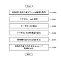
- query acquisition means for acquiring a plurality of time-series first frame images; skeleton structure detection means for detecting key points of an object included in each of the plurality of first frame images; feature quantity calculation means for calculating a feature quantity of the detected key point for each of the first frame images; change calculation means for calculating a direction of change of the feature amount along the time axis of the plurality of time-series first frame images; a search means for searching for a moving image using the calculated direction of change in the feature amount as a key; is provided.
- the computer a query acquisition step of acquiring a plurality of time-series first frame images; a skeletal structure detection step of detecting key points of an object included in each of the plurality of first frame images; a feature quantity calculation step of calculating a feature quantity of the detected key point for each of the first frame images; a change calculation step of calculating a direction of change of the feature amount along the time axis of the plurality of time-series first frame images; a search step of searching for a moving image using the calculated direction of change in the feature quantity as a key;
- An image processing method is provided for performing
- the computer query acquisition means for acquiring a plurality of time-series first frame images; Skeletal structure detection means for detecting key points of an object included in each of the plurality of first frame images; feature quantity calculation means for calculating a feature quantity of the detected key point for each of the first frame images; change calculation means for calculating a direction of change of the feature amount along the time axis of the plurality of time-series first frame images; search means for searching for a moving image using the calculated direction of change in the feature amount as a key;
- a program is provided to act as a
- FIG. 1 is a configuration diagram showing an overview of an image processing apparatus according to an embodiment
- FIG. 1 is a configuration diagram showing the configuration of an image processing apparatus according to Embodiment 1
- FIG. 4 is a flowchart showing an image processing method according to Embodiment 1
- 4 is a flowchart showing a classification method according to Embodiment 1
- 4 is a flowchart showing a search method according to Embodiment 1
- FIG. 5 is a diagram showing an example of detection of a skeletal structure according to Embodiment 1
- 1 is a diagram showing a human body model according to Embodiment 1;
- FIG. 5 is a diagram showing an example of detection of a skeletal structure according to Embodiment 1;
- FIG. 5 is a diagram showing an example of detection of a skeletal structure according to Embodiment 1;
- FIG. 5 is a diagram showing an example of detection of a skeletal structure according to Embodiment 1;
- 5 is a graph showing a specific example of a classification method according to Embodiment 1;
- FIG. 8 is a diagram showing a display example of classification results according to the first embodiment;
- FIG. 2 is a diagram for explaining a search method according to Embodiment 1;
- FIG. FIG. 2 is a diagram for explaining a search method according to Embodiment 1;
- FIG. FIG. 2 is a diagram for explaining a search method according to Embodiment 1;
- FIG. FIG. 2 is a diagram for explaining a search method according to Embodiment 1;
- FIG. FIG. 2 is a diagram for explaining a search method according to Embodiment 1;
- FIG. 2 is a diagram for explaining a search method according to Embodiment 1;
- FIG. FIG. 7 is a diagram showing a display example of search results according to Embodiment 1;
- 2 is a configuration diagram showing the configuration of an image processing apparatus according to Embodiment 2;
- FIG. 9 is a flowchart showing an image processing method according to Embodiment 2;
- 10 is a flowchart showing a specific example 1 of a height pixel number calculation method according to Embodiment 2.
- FIG. 10 is a diagram showing a human body model according to Embodiment 2;
- FIG. 10 is a diagram showing an example of detection of a skeletal structure according to Embodiment 2;
- 10 is a histogram for explaining a height pixel number calculation method according to Embodiment 2;
- FIG. 10 is a diagram showing an example of detection of a skeletal structure according to Embodiment 2;
- FIG. 10 is a diagram showing a three-dimensional human body model according to Embodiment 2;
- FIG. 11 is a diagram for explaining a height pixel number calculation method according to Embodiment 2;
- FIG. FIG. 11 is a diagram for explaining a height pixel number calculation method according to Embodiment 2;
- FIG. 11 is a diagram for explaining a height pixel number calculation method according to Embodiment 2;
- FIG. 10 is a diagram for explaining a normalization method according to Embodiment 2;
- FIG. 10 is a diagram for explaining a normalization method according to Embodiment 2;
- FIG. 10 is a diagram for explaining a normalization method according to Embodiment 2;
- FIG. It is a figure which shows the hardware structural example of an image processing apparatus.
- FIG. 11 is a configuration diagram showing the configuration of an image processing apparatus according to Embodiment 3;
- FIG. 12 is a diagram for explaining query frame selection processing according to the third embodiment;
- FIG. FIG. 12 is a diagram for explaining query frame selection processing according to the third embodiment;
- FIG. 11 is a diagram for explaining a process of calculating a direction of change in feature amount according to the third embodiment;
- FIG. 10 is a flow chart showing an example of the flow of processing of the image processing apparatus according to Embodiment 3;
- FIG. 11 is a configuration diagram showing the configuration of an image processing apparatus according to Embodiment 3;
- 10 is a flow chart showing an example of the flow of processing of the image processing apparatus according to Embodiment 3;
- Non-Patent Document 1 skeleton estimation technology
- Related skeleton estimation techniques such as OpenPose disclosed in Non-Patent Document 1, estimate a person's skeleton by learning various patterns of correct-correct image data.
- OpenPose disclosed in Non-Patent Document 1
- the skeletal structure estimated by skeletal estimation techniques such as OpenPose consists of "keypoints", which are characteristic points such as joints, and "bones (bone links)", which indicate links between keypoints. .
- keypoints characteristic points such as joints
- bones bone links
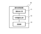
- FIG. 1 shows an overview of an image processing device 10 according to an embodiment.
- the image processing device 10 includes a skeleton detection section 11 , a feature amount calculation section 12 and a recognition section 13 .
- the skeleton detection unit 11 detects two-dimensional skeleton structures of a plurality of persons based on two-dimensional images acquired from a camera or the like.
- the feature amount calculation unit 12 calculates feature amounts of a plurality of two-dimensional skeleton structures detected by the skeleton detection unit 11 .
- the recognition unit 13 performs recognition processing of states of a plurality of persons based on the similarities of the plurality of feature amounts calculated by the feature amount calculation unit 12 .
- Recognition processing includes classification processing, search processing, and the like of a person's state.
- the 2D skeletal structure of a person is detected from a 2D image, and recognition processing such as classification and retrieval of the state of the person is performed based on the feature amount calculated from the 2D skeletal structure.
- recognition processing such as classification and retrieval of the state of the person is performed based on the feature amount calculated from the 2D skeletal structure.
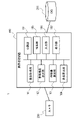
- FIG. 2 shows the configuration of the image processing apparatus 100 according to this embodiment.
- the image processing apparatus 100 constitutes an image processing system 1 together with a camera 200 and a database (DB) 201 .
- An image processing system 1 including an image processing apparatus 100 is a system that classifies and searches for a person's posture, action, or other state based on a person's skeletal structure estimated from an image.
- the camera 200 is an imaging unit such as a surveillance camera that generates a two-dimensional image.
- the camera 200 is installed at a predetermined location and captures an image of a person or the like in an imaging area from the installation location.
- the camera 200 is directly connected or connected via a network or the like so as to be able to output captured images (video) to the image processing apparatus 100 .
- the camera 200 may be provided inside the image processing apparatus 100 .
- the database 201 is a database that stores information (data) necessary for processing of the image processing apparatus 100, processing results, and the like.
- the database 201 contains images acquired by the image acquisition unit 101, detection results of the skeletal structure detection unit 102, data for machine learning, feature amounts calculated by the feature amount calculation unit 103, classification results of the classification unit 104, search unit 105 store search results, etc.
- the database 201 is directly connected to the image processing apparatus 100 so that data can be input/output as needed, or connected via a network or the like.
- the database 201 may be provided inside the image processing apparatus 100 as a nonvolatile memory such as a flash memory, a hard disk device, or the like.
- the image processing apparatus 100 includes an image acquisition unit 101, a skeleton structure detection unit 102, a feature quantity calculation unit 103, a classification unit 104, a search unit 105, an input unit 106, and a display unit 107.
- the configuration of each unit (block) is an example, and may be configured by other units as long as the method (operation) described later is possible.
- the image processing apparatus 100 is realized by a computer device such as a personal computer or a server that executes programs, for example, but may be realized by one device or by a plurality of devices on a network. good.
- the input unit 106, the display unit 107, and the like may be external devices.
- both the classification unit 104 and the search unit 105 may be provided, or only one of them may be provided.
- Both or one of the classification unit 104 and the retrieval unit 105 is a recognition unit that performs recognition processing of the person's state.
- the image acquisition unit 101 acquires a two-dimensional image including a person captured by the camera 200 .
- the image acquisition unit 101 acquires, for example, an image including a person (video including a plurality of images) captured by the camera 200 during a predetermined monitoring period. It should be noted that an image including a person prepared in advance may be acquired from the database 201 or the like instead of being acquired from the camera 200 .
- the skeletal structure detection unit 102 detects the 2D skeletal structure of the person in the image based on the acquired 2D image.
- the skeletal structure detection unit 102 detects skeletal structures of all persons recognized in the acquired image.
- the skeletal structure detection unit 102 detects the skeletal structure of a person based on recognized features such as the joints of the person, using a skeletal structure estimation technique using machine learning.
- the skeleton structure detection unit 102 uses, for example, a skeleton estimation technique such as OpenPose described in Non-Patent Document 1.
- the feature amount calculation unit 103 calculates the feature amount of the detected two-dimensional skeletal structure, associates the calculated feature amount with the image to be processed, and stores it in the database 201 .
- the feature amount of the skeletal structure indicates the features of the skeletal structure of the person, and serves as an element for classifying and retrieving the state of the person based on the skeletal structure of the person.
- this feature quantity includes a plurality of parameters (for example, classification elements to be described later).
- the feature quantity may be the feature quantity of the entire skeletal structure, the feature quantity of a part of the skeletal structure, or may include a plurality of feature quantities such as each part of the skeletal structure.
- the feature amount is a feature amount obtained by machine-learning the skeletal structure, the size of the skeletal structure from the head to the foot on the image, and the like.
- the size of the skeletal structure is the vertical height, area, etc. of the skeletal region containing the skeletal structure on the image.
- the vertical direction (height direction or vertical direction) is the vertical direction (Y-axis direction) in the image, for example, the direction perpendicular to the ground (reference plane).
- the left-right direction (horizontal direction) is the left-right direction (X-axis direction) in the image, for example, the direction parallel to the ground.
- features that are robust to classification and search processing it is preferable to use features that are robust to classification and search processing.
- a feature quantity that is robust to the person's orientation or body shape may be used.
- the classification unit 104 classifies (clusters) a plurality of skeletal structures stored in the database 201 based on the degree of similarity of feature amounts of the skeletal structures. It can be said that the classification unit 104 classifies the states of a plurality of persons based on the feature amount of the skeletal structure as the process of recognizing the states of the persons.
- the degree of similarity is the distance between features of the skeleton structure.
- the classification unit 104 may classify the skeletal structure according to the similarity of the feature amount of the entire skeletal structure, or may classify the skeletal structure according to the similarity of the feature amount of part of the skeletal structure. Both hands) and the second part (both feet, for example) may be classified according to the similarity of feature amounts.
- the posture of the person may be classified based on the feature amount of the skeletal structure of the person in each image, or the behavior of the person may be classified based on the change in the feature amount of the skeletal structure of the person in a plurality of consecutive images in time series. can be classified. That is, the classification unit 104 can classify the state of the person, including the posture and behavior of the person, based on the feature amount of the skeletal structure. For example, the classification unit 104 classifies a plurality of skeletal structures in a plurality of images captured during a predetermined monitoring period. The classification unit 104 obtains the degree of similarity between the feature quantities to be classified, and classifies the skeletal structures with a high degree of similarity into the same cluster (group of similar postures). It should be noted that the user may be allowed to specify the classification condition as in the search. The classification unit 104 stores the classification result of the skeletal structure in the database 201 and displays it on the display unit 107 .
- the search unit 105 searches a plurality of skeleton structures stored in the database 201 for a skeleton structure with a high degree of similarity to the feature quantity of the search query (query state). It can be said that the search unit 105 searches for a person's state corresponding to a search condition (query state) from among a plurality of persons' states based on the feature amount of the skeletal structure as the recognition processing of the person's state. Similar to classification, similarity is the distance between skeletal structure features.
- the search unit 105 may search based on the similarity of the feature amount of the entire skeletal structure, or may search based on the similarity of the feature amount of a part of the skeletal structure.
- Both hands) and the second part may be retrieved based on the similarity of feature amounts.
- the posture of a person may be retrieved based on the feature amount of the skeletal structure of the person in each image, or the behavior of the person may be searched based on changes in the feature amount of the skeletal structure of the person in a plurality of images that are consecutive in time series. can be searched. That is, the search unit 105 can search for a person's state, including the person's posture and behavior, based on the feature amount of the skeletal structure. For example, the search unit 105 searches feature amounts of a plurality of skeletal structures in a plurality of images captured during a predetermined monitoring period, similarly to the classification target.
- the skeleton structure (posture) specified by the user from among the classification results displayed by the classification unit 104 is used as a search query (search key).
- search query may be selected from among a plurality of unclassified skeletal structures, and the user may input a skeletal structure to be the search query.
- the search unit 105 searches for a feature amount having a high degree of similarity with the feature amount of the skeleton structure of the search query from among the feature amounts to be searched.
- the search unit 105 stores the search result of the feature amount in the database 201 and displays it on the display unit 107 .
- the input unit 106 is an input interface that acquires information input by the user who operates the image processing apparatus 100 .
- the user is a surveillance person who monitors a person in a suspicious state from an image of a surveillance camera.
- the input unit 106 is, for example, a GUI (Graphical User Interface), and receives information according to user operations from an input device such as a keyboard, mouse, or touch panel.
- the input unit 106 receives, as a search query, the skeletal structure of a specified person from among the skeletal structures (postures) classified by the classifying unit 104 .
- the display unit 107 is a display unit that displays the result of the operation (processing) of the image processing apparatus 100, and is, for example, a display device such as a liquid crystal display or an organic EL (Electro Luminescence) display.
- a display unit 107 displays the classification result of the classification unit 104 and the search result of the search unit 105 on a GUI according to the degree of similarity or the like.
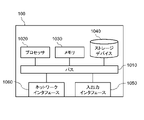
- FIG. 39 is a diagram showing a hardware configuration example of the image processing apparatus 100.
- the image processing apparatus 100 has a bus 1010 , a processor 1020 , a memory 1030 , a storage device 1040 , an input/output interface 1050 and a network interface 1060 .
- the bus 1010 is a data transmission path for the processor 1020, the memory 1030, the storage device 1040, the input/output interface 1050, and the network interface 1060 to exchange data with each other.
- the method of connecting processors 1020 and the like to each other is not limited to bus connection.
- the processor 1020 is a processor realized by a CPU (Central Processing Unit), a GPU (Graphics Processing Unit), or the like.
- the memory 1030 is a main memory implemented by RAM (Random Access Memory) or the like.
- the storage device 1040 is an auxiliary storage device realized by a HDD (Hard Disk Drive), SSD (Solid State Drive), memory card, ROM (Read Only Memory), or the like.
- the storage device 1040 stores program modules for realizing each function of the image processing apparatus 100 (for example, the image acquisition unit 101, the skeleton structure detection unit 102, the feature value calculation unit 103, the classification unit 104, the search unit 105, and the input unit 106). is doing.
- Each function corresponding to the program module is realized by the processor 1020 reading each program module into the memory 1030 and executing it.
- Storage device 1040 may also function as database 201 .
- the input/output interface 1050 is an interface for connecting the image processing apparatus 100 and various input/output devices. If the database 201 is located outside the image processing apparatus 100 , the image processing apparatus 100 may be connected to the database 201 via the input/output interface 1050 .
- a network interface 1060 is an interface for connecting the image processing apparatus 100 to a network.
- This network is, for example, a LAN (Local Area Network) or a WAN (Wide Area Network).
- a method for connecting the network interface 1060 to the network may be a wireless connection or a wired connection.
- Image processing device 100 may communicate with camera 200 via network interface 1060 . If the database 201 is located outside the image processing apparatus 100 , the image processing apparatus 100 may be connected to the database 201 via the network interface 1060 .
- FIG. 3 to 5 show the operation of the image processing apparatus 100 according to this embodiment.
- 3 shows the flow from image acquisition to search processing in the image processing apparatus 100
- FIG. 4 shows the flow of the classification processing (S104) in FIG. 3
- FIG. 5 shows the search processing (S105) in FIG. showing the flow.
- the image processing device 100 acquires an image from the camera 200 (S101).
- the image acquisition unit 101 acquires an image of a person in order to classify or search from the skeletal structure, and stores the acquired image in the database 201 .
- the image acquisition unit 101 acquires, for example, a plurality of images captured during a predetermined monitoring period, and performs subsequent processing on all persons included in the plurality of images.
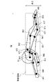
- FIG. 6 shows an example of skeletal structure detection. As shown in FIG. 6, an image acquired from a monitoring camera or the like includes a plurality of persons, and the skeletal structure of each person included in the image is detected.
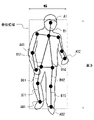
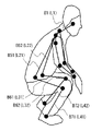
- FIG. 7 shows the skeletal structure of the human body model 300 detected at this time
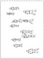
- FIGS. 8 to 10 show detection examples of the skeletal structure.
- a skeleton structure detection unit 102 detects the skeleton structure of a human body model (two-dimensional skeleton model) 300 as shown in FIG.
- the human body model 300 is a two-dimensional model composed of key points such as human joints and bones connecting the key points.
- the skeletal structure detection unit 102 extracts feature points that can be keypoints from the image, refers to information obtained by machine learning the image of the keypoints, and detects each keypoint of the person.
- the key points of the person are head A1, neck A2, right shoulder A31, left shoulder A32, right elbow A41, left elbow A42, right hand A51, left hand A52, right hip A61, left hip A62, right knee A71. , left knee A72, right foot A81, and left foot A82.
- B72 is detected.
- the skeletal structure detection unit 102 stores the detected skeletal structure of the person in the database 201 .
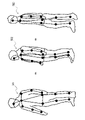
- FIG. 8 is an example of detecting a person standing upright.
- an upright person is imaged from the front, and bones B1, B51 and B52, B61 and B62, and B71 and B72 viewed from the front are detected without overlapping each other.
- the bones B61 and B71 are slightly more bent than the left leg bones B62 and B72.
- Fig. 9 is an example of detecting a person who is crouching.
- a crouching person is imaged from the right side, and bones B1, B51 and B52, B61 and B62, and B71 and B72 are detected from the right side, and the right leg bone B61 is detected. And the bone B71 and the bones B62 and B72 of the left leg are greatly bent and overlapped.
- FIG. 10 is an example of detecting a sleeping person.
- a sleeping person is imaged obliquely from the front left, bones B1, B51 and B52, bones B61 and B62, bones B71 and B72 are detected from the oblique front left, and bones B71 and B72 are detected.
- the bones B61 and B71 of the left leg and the bones B62 and B72 of the left leg are bent and overlapped.
- the image processing apparatus 100 calculates the feature quantity of the detected skeletal structure (S103). For example, when the height and area of a skeletal region are used as feature quantities, the feature quantity calculator 103 extracts a region containing a skeletal structure and obtains the height (number of pixels) and area (pixel area) of that region. The height and area of the skeletal region are obtained from the coordinates of the edge of the extracted skeletal region and the coordinates of the keypoints of the edge. The feature amount calculation unit 103 stores the obtained feature amount of the skeletal structure in the database 201 .
- a skeletal region including all bones is extracted from the skeletal structure of an upright person.
- the upper end of the skeletal region is the head key point A1
- the lower end of the skeletal region is the left leg key point A82
- the left end of the skeletal region is the right elbow key point A41
- the right end of the skeletal region is the left hand key point A52.
- the height of the skeletal region is obtained from the difference between the Y coordinates of the keypoint A1 and the keypoint A82.
- the width of the skeleton region is obtained from the difference between the X coordinates of the key points A41 and A52, and the area is obtained from the height and width of the skeleton region.
- a skeletal region including all bones is extracted from the skeletal structure of a squatting person.
- the upper end of the skeletal region is the head key point A1
- the lower end of the skeletal region is the right leg key point A81
- the left end of the skeletal region is the right hip key point A61
- the right end of the skeletal region is the right hand key point A51.
- the height of the skeletal region is obtained from the difference between the Y coordinates of the keypoints A1 and A81.
- the width of the skeleton region is obtained from the difference between the X coordinates of the key points A61 and A51, and the area is obtained from the height and width of the skeleton region.
- a skeletal region including all bones is extracted from the skeletal structure of a person lying down in the horizontal direction of the image.
- the upper end of the skeletal region is the left shoulder key point A32
- the lower end of the skeletal region is the left hand key point A52
- the left end of the skeletal region is the right hand key point A51
- the right end of the skeletal region is the left foot key point A82. Therefore, the height of the skeletal region is obtained from the difference between the Y coordinates of the keypoints A32 and A52.
- the width of the skeleton region is obtained from the difference between the X coordinates of the key points A51 and A82, and the area is obtained from the height and width of the skeleton region.
- the image processing apparatus 100 performs classification processing (S104).
- the classification unit 104 calculates the similarity of the calculated feature amount of the skeletal structure (S111), and classifies the skeletal structure based on the calculated feature amount (S112). .
- the classification unit 104 obtains the degree of similarity of feature amounts between all the skeletal structures stored in the database 201 to be classified, and classifies (clusters) the skeletal structures (postures) with the highest degree of similarity into the same cluster. . Furthermore, the similarity between the classified clusters is calculated and classified, and the classification is repeated until a predetermined number of clusters is obtained.
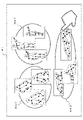
- FIG. 11 shows an image of the classification result of the feature amount of the skeletal structure.
- FIG. 11 is an image of cluster analysis using two-dimensional classification elements.
- the two classification elements are, for example, the height of the skeleton region and the area of the skeleton region.
- a plurality of skeletal structure feature quantities are classified into three clusters C1 to C3.
- Clusters C1 to C3 correspond to postures such as a standing posture, a sitting posture, and a lying posture, and skeletal structures (persons) are classified for each similar posture.
- various classification methods can be used by classifying based on the feature amount of the skeletal structure of a person.
- the classification method may be set in advance, or may be arbitrarily set by the user.
- the classification may be performed by the same method as the retrieval method described later. In other words, classification may be performed using classification conditions similar to the search conditions.
- the classification unit 104 classifies according to the following classification method. Any classification method may be used, or a combination of arbitrarily selected classification methods may be used.
- Classification method 1 Classification according to a plurality of hierarchies Classification is performed by hierarchically combining classification according to the skeletal structure of the whole body, classification according to the skeletal structure of the upper and lower bodies, classification according to the skeletal structure of the arms and legs, and the like. That is, classification may be performed based on the feature amounts of the first portion and the second portion of the skeletal structure, and further, the feature amounts of the first portion and the second portion may be weighted for classification.
- Classification method 2 Classification based on a plurality of images in time series Classification is performed based on the feature amount of the skeletal structure in a plurality of images that are consecutive in time series. For example, feature amounts may be accumulated in the time-series direction and classified based on the cumulative value. Further, the classification may be based on the change (variation amount) of the feature amount of the skeletal structure in a plurality of consecutive images.
- the classification unit 104 displays the classification result of the skeletal structure (S113).
- the classification unit 104 acquires necessary skeletal structures and images of persons from the database 201, and displays the skeletal structures and persons for each similar posture (cluster) on the display unit 107 as a classification result.
- FIG. 12 shows a display example when postures are classified into three. For example, as shown in FIG. 12, posture areas WA1 to WA3 for each posture are displayed in the display window W1, and the skeletal structure and the person (image) of the posture respectively corresponding to the posture areas WA1 to WA3 are displayed.
- the posture area WA1 is, for example, a display area for a standing posture, and displays a skeletal structure and a person that are classified into the cluster C1 and resemble a standing posture.
- the posture area WA2 is, for example, a display area for a sitting posture, and displays a skeletal structure and a person that are classified into the cluster C2 and resemble a sitting posture.
- the posture area WA3 is, for example, a display area of a sleeping posture, and displays a skeletal structure and a person that are classified into the cluster C2 and resemble a sleeping posture.
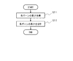
- the image processing apparatus 100 performs search processing (S105).
- the search unit 105 receives input of search conditions (S121), and searches for a skeletal structure based on the search conditions (S122).
- the search unit 105 receives an input of a search query, which is a search condition, from the input unit 106 according to user's operation.
- the user designates (selects) the skeletal structure of the posture to be searched from among the posture areas WA1 to WA3 displayed in the display window W1. .
- the search unit 105 uses the skeleton structure specified by the user as a search query, and searches for skeleton structures with high similarity in feature quantity from among all skeleton structures stored in the database 201 to be searched.
- the search unit 105 calculates the degree of similarity between the feature quantity of the skeleton structure of the search query and the feature quantity of the skeleton structure to be searched, and extracts the skeleton structure with the calculated degree of similarity higher than a predetermined threshold.
- a feature amount calculated in advance may be used, or a feature amount obtained at the time of searching may be used.
- the search query may be input by moving each part of the skeletal structure according to the user's operation, or may be a posture demonstrated by the user in front of the camera as the search query.
- search unit 105 searches using the following search method. Any search method may be used, or any combination of search methods may be selected.
- search may be performed by combining multiple search methods (search conditions) with logical expressions (for example, AND (logical product), OR (logical sum), and NOT (negative)).
- search condition may be "(posture raising right hand) AND (posture raising left leg)".
- search method 2 When a part of the person's body is hidden in the partial search image, the search is performed using only the information of the recognizable part. For example, as in the skeletal structures 511 and 512 in FIG. 14, even if the keypoint of the left foot cannot be detected because the left foot is hidden, it can be searched using the feature amounts of other detected keypoints. Therefore, it can be determined that the skeletal structures 511 and 512 have the same posture at the time of retrieval (at the time of classification). In other words, classification and retrieval can be performed using feature amounts of some keypoints instead of all keypoints. In the example of the skeletal structures 521 and 522 in FIG.
- the feature amount of the upper body key points (A1, A2, A31, A32, A41, A42, A51, A52) is used as the search query. Therefore, it can be determined that they are in the same posture. Also, a portion (feature point) to be searched may be searched with a weight, or the threshold for similarity determination may be changed. When a part of the body is hidden, the hidden part may be ignored, or the hidden part may be taken into account in the search. By searching including hidden parts, it is possible to search postures in which the same part is hidden.
- (Search method 3) Search ignoring the left and right of the skeletal structure
- the skeletal structure of the person whose right and left sides are opposite to each other is searched as the same skeletal structure.
- the skeletal structure 531 and the skeletal structure 532 differ in the positions of the right hand key point A51, the right elbow key point A41, the left hand key point A52, and the left elbow key point A42. are the same.
- Search method 4 Search using vertical and horizontal feature amounts After performing a search using only the person's vertical (Y-axis) feature amount, the obtained result is further used for the person's horizontal (X-axis) feature amount. to search.
- search method 5 Search using a plurality of images in time series A search is performed based on the feature amount of the skeletal structure in a plurality of images that are consecutive in time series. For example, feature amounts may be accumulated in the time-series direction and searched based on the cumulative value. Furthermore, the search may be performed based on the change (variation amount) of the feature amount of the skeletal structure in a plurality of consecutive images.
- the search unit 105 displays the search result of the skeletal structure (S123).
- the search unit 105 acquires necessary skeletal structures and images of persons from the database 201 and displays the skeletal structures and persons obtained as search results on the display unit 107 .
- search results are displayed for each search query.
- FIG. 17 shows a display example when searching by three search queries (postures).
- the skeletal structures and persons of the specified search queries Q10, Q20, and Q30 are displayed on the left end, and each search query is displayed on the right side of the search queries Q10, Q20, and Q30.
- the skeletal structures and persons of the search results Q11, Q21, and Q31 are displayed side by side.
- the order in which the search results are displayed next to the search query may be the order in which the relevant skeletal structure was found, or the order in which the similarity is high.
- the parts (feature points) of the partial search are weighted for retrieval, they may be displayed in the order of similarity calculated by weighting. It may be displayed in the order of similarity calculated only from the portions (feature points) selected by the user. Further, images (frames) before and after the time series may be cut out for a certain period of time and displayed, centering on the image (frame) of the search result.
- the present embodiment it is possible to detect the skeletal structure of a person from a two-dimensional image and perform classification and retrieval based on the feature amount of the detected skeletal structure. As a result, it is possible to classify the postures having a high degree of similarity, and to search for similar postures having a high degree of similarity with the search query (search key).
- search key By classifying and displaying similar postures from the image, the posture of the person in the image can be grasped without the user specifying the posture or the like. Since the user can specify the posture of the search query from among the classification results, even if the user does not know the details of the posture to be searched in advance, it is possible to search for the desired posture.
- classification and retrieval can be performed using the whole or part of a person's skeletal structure as a condition, enabling flexible classification and retrieval.
- Embodiment 2 will be described below with reference to the drawings.
- the feature amount is obtained by normalization using the height of the person. Others are the same as those of the first embodiment.
- FIG. 18 shows the configuration of the image processing apparatus 100 according to this embodiment.
- the image processing apparatus 100 further includes a height calculator 108 in addition to the configuration of the first embodiment. Note that the feature amount calculation unit 103 and the height calculation unit 108 may be integrated into one processing unit.
- a height calculation unit (height estimation unit) 108 calculates the height of a person in a two-dimensional image when standing upright (height in pixels) based on the two-dimensional skeletal structure detected by the skeletal structure detection unit 102 ( presume. It can also be said that the number of height pixels is the height of the person in the two-dimensional image (the length of the whole body of the person in the two-dimensional image space). The height calculation unit 108 obtains the number of height pixels (the number of pixels) from the length of each bone of the detected skeletal structure (the length in the two-dimensional image space).
- specific examples 1 to 3 are used as the method for obtaining the height pixel count. Any one of the methods of Examples 1 to 3 may be used, or a plurality of arbitrarily selected methods may be used in combination.
- the number of height pixels is obtained by totaling the length of the bones from the head to the feet among the bones of the skeletal structure. If the skeletal structure detection unit 102 (skeletal structure estimation technology) does not output the top of the head and the feet, it can be corrected by multiplying by a constant as necessary.
- the number of height pixels is calculated using a human body model that indicates the relationship between the length of each bone and the length of the whole body (height in a two-dimensional image space).
- the number of height pixels is calculated by fitting a three-dimensional human body model to a two-dimensional skeletal structure.
- the feature amount calculation unit 103 of the present embodiment is a normalization unit that normalizes the skeletal structure (skeletal information) of the person based on the calculated number of pixels of the height of the person.
- the feature amount calculation unit 103 stores the normalized feature amount (normalized value) of the skeletal structure in the database 201 .
- the feature amount calculation unit 103 normalizes the height on the image of each key point (feature point) included in the skeletal structure by the number of height pixels.
- the height direction is the vertical direction (Y-axis direction) in the two-dimensional coordinate (XY coordinate) space of the image.
- the height of the keypoint can be obtained from the Y coordinate value (the number of pixels) of the keypoint.
- the height direction may be the direction of the vertical projection axis (vertical projection direction) obtained by projecting the direction of the vertical axis perpendicular to the ground (reference plane) in the three-dimensional coordinate space of the real world onto the two-dimensional coordinate space.
- the height of the keypoint is obtained by calculating the vertical projection axis by projecting the axis perpendicular to the ground in the real world onto the two-dimensional coordinate space based on the camera parameters, and calculating the value along this vertical projection axis (the number of pixels ) can be obtained from
- the camera parameters are imaging parameters of an image.
- the camera parameters are the attitude, position, imaging angle, focal length, etc. of the camera 200 .
- the camera 200 an object whose length and position are known in advance can be imaged, and camera parameters can be obtained from the image. Distortion occurs at both ends of the captured image, and the vertical direction of the real world may not match the vertical direction of the image.
- the parameters of the camera that captured the image it is possible to know how much the vertical direction in the real world is tilted in the image. Therefore, by normalizing the values of the keypoints along the vertical projection axis projected into the image based on the camera parameters by the height, it is possible to convert the keypoints into features considering the deviation between the real world and the image. can.
- the left-right direction is the left-right direction (X-axis direction) in the two-dimensional coordinate (XY coordinate) space of the image, or the direction parallel to the ground in the three-dimensional coordinate space of the real world. is projected onto the two-dimensional coordinate space.
- FIG. 19 to 23 show the operation of the image processing apparatus 100 according to this embodiment.
- FIG. 19 shows the flow from image acquisition to search processing in the image processing apparatus 100
- FIGS. 23 shows the flow of the normalization process (S202) in FIG.
- the image processing apparatus 100 After image acquisition (S101) and skeletal structure detection (S102), the image processing apparatus 100 performs height pixel count calculation processing based on the detected skeletal structure (S201).
- the height of the skeletal structure of the person in the image when standing upright is the number of height pixels (h)
- the height of each keypoint of the skeletal structure in the state of the person in the image is the keypoint. Let the height be (yi). Specific examples 1 to 3 of the height pixel number calculation process will be described below.
- the length of the bone from the head to the foot is used to obtain the number of pixels of the height.
- the height calculation unit 108 acquires the length of each bone (S211), and totals the acquired lengths of each bone (S212).
- the height calculation unit 108 obtains the length of the bones on the two-dimensional image from the head to the feet of the person and obtains the number of pixels of the height. 24, bone B1 (length L1), bone B51 (length L21), bone B61 (length L31) and bone B71 (length L41), or , bone B1 (length L1), bone B52 (length L22), bone B62 (length L32), and bone B72 (length L42).
- the length of each bone can be obtained from the coordinates of each keypoint in the two-dimensional image.
- the height pixel number (h) is calculated by multiplying L1+L21+L31+L41 or L1+L22+L32+L42 by a correction constant.
- the longer value is used as the number of height pixels. That is, each bone has the longest length in the image when the image is taken from the front, and is displayed to be short when the bone is tilted in the depth direction with respect to the camera. Therefore, the longer bones are more likely to be imaged from the front, and are considered to be closer to the true values. Therefore, it is preferable to choose the longer value.
- bone B1, bone B51 and bone B52, bone B61 and bone B62, bone B71 and bone B72 are detected without overlapping each other.
- the sums of these bones, L1+L21+L31+L41 and L1+L22+L32+L42, are calculated, and the value obtained by multiplying L1+L22+L32+L42 on the left leg side where the length of the detected bone is longer by a correction constant is taken as the number of height pixels.
- bone B1, bone B51 and bone B52, bone B61 and bone B62, bone B71 and bone B72 are respectively detected, and bone B61 and bone B71 of the right leg and bone B62 and bone B72 of the left leg are overlapped.
- the sums of these bones, L1+L21+L31+L41 and L1+L22+L32+L42, are calculated, and the value obtained by multiplying L1+L21+L31+L41 on the right leg side where the length of the detected bone is longer by a correction constant is taken as the height pixel number.
- bone B1, bone B51 and bone B52, bone B61 and bone B62, bone B71 and bone B72 are respectively detected, and bone B61 and bone B71 of the right leg and bone B62 and bone B72 of the left leg are overlapped.
- the sums of these bones, L1+L21+L31+L41 and L1+L22+L32+L42, are calculated, and the value obtained by multiplying L1+L22+L32+L42 on the left leg side where the length of the detected bone is longer by a correction constant is taken as the number of height pixels.
- the height can be obtained by totaling the length of the bones from the head to the feet, the number of pixels of the height can be obtained by a simple method.
- the height pixel count can be accurately calculated even when the whole person is not shown in the image, such as when the person is crouching. can be estimated.
- the number of height pixels is obtained using a two-dimensional skeleton model that indicates the relationship between the length of bones included in the two-dimensional skeleton structure and the length of the whole body of a person in the two-dimensional image space.
- FIG. 28 is a human body model (two-dimensional skeleton model) 301 used in Specific Example 2, showing the relationship between the length of each bone on the two-dimensional image space and the length of the whole body on the two-dimensional image space.
- the relationship between the length of each bone of an average person and the length of the whole body is associated with each bone of the human body model 301 .
- the length of the head bone B1 is the length of the whole body x 0.2 (20%)
- the length of the right hand bone B41 is the length of the whole body x 0.15 (15%)
- the length of the right leg is
- the length of bone B71 is the length of the whole body ⁇ 0.25 (25%).
- the average length of the whole body can be obtained from the length of each bone.
- a human body model may be prepared for each person's attributes such as age, sex, and nationality. As a result, the length of the whole body (height) can be obtained appropriately according to the attributes of the person.
- the height calculation unit 108 acquires the length of each bone (S221).
- the height calculator 108 acquires the lengths of all bones (lengths in the two-dimensional image space) in the detected skeletal structure.
- FIG. 29 shows an example in which a skeletal structure is detected by capturing an image of a squatting person from the right rear oblique direction.
- the bones of the head, left arm, and left hand cannot be detected. Therefore, the lengths of the detected bones B21, B22, B31, B41, B51, B52, B61, B62, B71, and B72 are obtained.
- the height calculation unit 108 calculates the number of height pixels from the length of each bone based on the human body model, as shown in FIG. 21 (S222).
- the height calculator 108 refers to a human body model 301 showing the relationship between each bone and the length of the whole body as shown in FIG. 28, and obtains the number of height pixels from the length of each bone.
- the length of the bone B41 on the right hand is the length of the whole body ⁇ 0.15
- the length of the bone B41/0.15 is used to obtain the height pixel number based on the bone B41.
- the length of the bone B71 of the right leg is the length of the whole body ⁇ 0.25, the length of the bone B71/0.25 is used to obtain the height pixel number based on the bone B71.
- the human body model referred to at this time is, for example, the human body model of an average person, but the human body model may be selected according to the attributes of the person, such as age, gender, and nationality. For example, when a person's face is shown in the captured image, the person's attribute is identified based on the face, and a human body model corresponding to the identified attribute is referred to. By referring to machine-learned face information for each attribute, it is possible to recognize a person's attribute from the facial features in the image. Also, when the attributes of a person cannot be identified from the image, an average human body model may be used.
- the height pixel count calculated from the length of the bone may be corrected by camera parameters. For example, if the camera is placed at a high position and the person is shot looking down, the horizontal length of the shoulder bones, etc. in the two-dimensional skeletal structure is not affected by the camera's depression angle, but the vertical length of the neck-waist bones, etc. The length decreases as the depression angle of the camera increases. As a result, the height pixel count calculated from the horizontal length of the shoulder-width bone tends to be larger than the actual number. Therefore, by using the camera parameters, it is possible to know at what angle the person is looking down at the camera. This makes it possible to more accurately calculate the number of height pixels.
- the height calculation unit 108 calculates the optimal value of the number of height pixels, as shown in FIG. 21 (S223).
- the height calculation unit 108 calculates the optimal value of the height pixel count from the height pixel count obtained for each bone. For example, as shown in FIG. 30, a histogram of the number of height pixels obtained for each bone is generated, and the largest number of height pixels is selected. In other words, among the plurality of height pixel numbers obtained based on the plurality of bones, the height pixel number that is longer than the others is selected. For example, the upper 30% are set as effective values, and the number of height pixels by bones B71, B61, and B51 in FIG. 30 is selected.
- the average of the selected height pixel counts may be obtained as the optimum value, or the maximum height pixel count may be obtained as the optimum value. Since the height is calculated from the length of the bones in the two-dimensional image, if the bones are not formed from the front, that is, if the bones are photographed tilted in the depth direction when viewed from the camera, the length of the bones will be measured from the front. shorter than the case. Then, a value with a large height pixel count is more likely to have been captured from the front than a value with a small height pixel count, and is a more plausible value.
- a human body model showing the relationship between bones in a two-dimensional image space and the length of the whole body is used to obtain the number of height pixels based on the bones of the detected skeletal structure. Even if is not obtained, the number of height pixels can be obtained from some bones. In particular, by adopting the larger value among the values obtained from a plurality of bones, the number of height pixels can be estimated with high accuracy.
- a 2D skeletal structure is fitted to a 3D human body model (3D skeletal model), and a whole body skeletal vector is obtained using the number of height pixels of the fitted 3D human body model.
- the height calculation unit 108 first calculates camera parameters based on the image captured by the camera 200 (S231).
- the height calculator 108 extracts an object whose length is known in advance from a plurality of images captured by the camera 200, and obtains camera parameters from the size (number of pixels) of the extracted object. Note that the camera parameters may be obtained in advance, and the obtained camera parameters may be obtained as necessary.
- the height calculation unit 108 adjusts the placement and height of the 3D human body model (S232).
- the height calculation unit 108 prepares a three-dimensional human body model for height pixel number calculation for the detected two-dimensional skeletal structure, and arranges it in the same two-dimensional image based on the camera parameters.
- the "relative positional relationship between the camera and the person in the real world" is specified from the camera parameters and the two-dimensional skeleton structure. For example, if the position of the camera is assumed to be coordinates (0, 0, 0), the coordinates (x, y, z) of the person's standing (or sitting) position are specified. Then, by assuming an image when the 3D human body model is arranged at the same position (x, y, z) as the specified person and captured, the 2D skeletal structure and the 3D human body model are superimposed.
- FIG. 31 is an example of detecting a two-dimensional skeletal structure 401 by capturing an image of a crouching person from the front left diagonally.
- the two-dimensional skeleton structure 401 has two-dimensional coordinate information. It is preferable that all bones are detected, but some bones may not be detected.
- a three-dimensional human body model 402 as shown in FIG. 32 is prepared for this two-dimensional skeletal structure 401 .
- a three-dimensional human body model (three-dimensional skeleton model) 402 is a skeleton model having three-dimensional coordinate information and having the same shape as the two-dimensional skeleton structure 401 .
- a prepared three-dimensional human body model 402 is arranged and superimposed on the detected two-dimensional skeletal structure 401 . Also, the height of the three-dimensional human body model 402 is adjusted so as to match the two-dimensional skeletal structure 401 while being superimposed.
- the three-dimensional human body model 402 prepared at this time may be a model in a state close to the posture of the two-dimensional skeletal structure 401 as shown in FIG. 33, or may be a model in an upright state.
- a technique of estimating a posture in a three-dimensional space from a two-dimensional image using machine learning may be used to generate the three-dimensional human body model 402 with the estimated posture.
- a three-dimensional posture can be estimated from a two-dimensional image by learning joint information in a two-dimensional image and joints in a three-dimensional space.
- the height calculation unit 108 fits the 3D human body model to the 2D skeletal structure as shown in FIG. 22 (S233). As shown in FIG. 34, the height calculation unit 108 calculates the three-dimensional human body model 402 so that the postures of the three-dimensional human body model 402 and the two-dimensional skeletal structure 401 match each other in a state in which the three-dimensional human body model 402 is superimposed on the two-dimensional skeletal structure 401 .
- the dimensional human body model 402 is deformed. That is, the height, body orientation, and joint angles of the three-dimensional human body model 402 are adjusted so that the difference from the two-dimensional skeletal structure 401 is optimized.
- the joints of the three-dimensional human body model 402 are rotated within the human movable range, the entire three-dimensional human body model 402 is rotated, and the overall size is adjusted.
- the fitting between the three-dimensional human body model and the two-dimensional skeletal structure is performed in a two-dimensional space (two-dimensional coordinates). That is, the three-dimensional human body model is mapped into a two-dimensional space, and the three-dimensional human body model is transformed into a two-dimensional skeletal structure in consideration of how the deformed three-dimensional human body model changes in the two-dimensional space (image). Optimize.
- the height calculation unit 108 calculates the number of height pixels of the fitted three-dimensional human body model, as shown in FIG. 22 (S234).
- the difference between the three-dimensional human body model 402 and the two-dimensional skeletal structure 401 disappears and the postures match as shown in FIG.
- the height pixel number is calculated from the bone length (pixel number) from the head to the feet when the three-dimensional human body model 402 is erected.
- the lengths of the bones from the head to the feet of the three-dimensional human body model 402 may be totaled.
- the 3D human body model is fitted to the 2D skeletal structure based on the camera parameters, and the number of height pixels is obtained based on the 3D human body model. That is, even if the error is large because all the bones are projected obliquely, the number of height pixels can be estimated with high accuracy.
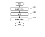
- the image processing apparatus 100 performs normalization processing (S202) following the height pixel count calculation processing.
- the feature amount calculation unit 103 calculates the keypoint height (S241).
- the feature amount calculation unit 103 calculates the keypoint heights (the number of pixels) of all keypoints included in the detected skeletal structure.
- the keypoint height is the length (number of pixels) in the height direction from the lowest end of the skeletal structure (for example, the keypoint of one of the legs) to that keypoint.
- the keypoint height is obtained from the Y coordinate of the keypoint in the image.
- the keypoint height may be obtained from the length in the direction along the vertical projection axis based on the camera parameters.
- the height (yi) of the neck keypoint A2 is the Y coordinate of the keypoint A2 minus the Y coordinate of the right leg keypoint A81 or the left leg keypoint A82.
- a reference point is a reference point for representing the relative height of a keypoint.
- the reference point may be set in advance or may be selected by the user.
- the reference point is preferably the center of the skeletal structure or higher than the center (above in the vertical direction of the image), for example, the coordinates of the neck key point. Note that the coordinates of the head or other key points may be used as the reference point instead of the neck.
- Arbitrary coordinates for example, the center coordinates of the skeleton structure, etc. may be used as the reference point without being limited to the key point.
- the feature amount calculation unit 103 normalizes the keypoint height (yi) by the number of height pixels (S243).
- the feature amount calculation unit 103 normalizes each keypoint using the keypoint height, the reference point, and the height pixel count of each keypoint. Specifically, the feature amount calculation unit 103 normalizes the relative height of the keypoint with respect to the reference point by the number of height pixels.
- the Y coordinate of the reference point (key point of the neck) is set to (yc), and the feature amount (normalized value) is obtained using the following equation (1).
- (yi) and (yc) are converted into values in the direction along the vertical projection axis.
- the coordinates (x0, y0), (x1, y1), . is converted into an 18-dimensional feature amount as follows.
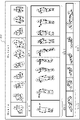
- FIG. 36 shows an example of the feature amount of each keypoint calculated by the feature amount calculation unit 103.
- the feature amount of the key point A2 is 0.0
- the feature amount of the key point A31 of the right shoulder and the key point A32 of the left shoulder at the same height as the neck are also 0.0.
- the feature value of the keypoint A1 of the head higher than the neck is -0.2.
- the right hand keypoint A51 and left hand keypoint A52 lower than the neck have a feature quantity of 0.4
- the right foot keypoint A81 and left foot keypoint A82 have a feature quantity of 0.9.
- the feature amount (normalized value) of the present embodiment indicates the feature in the height direction (Y direction) of the skeletal structure (key point), and influences the change in the lateral direction (X direction) of the skeletal structure. do not receive
- the skeletal structure of a person is detected from a two-dimensional image, and the number of height pixels (height when standing upright in the two-dimensional image space) obtained from the detected skeletal structure is used to Normalize each keypoint of the skeleton structure.
- this normalized feature amount it is possible to improve robustness when performing classification, search, and the like. That is, the feature amount of the present embodiment is not affected by changes in the horizontal direction of the person as described above, and is therefore highly robust against changes in the orientation of the person and the body shape of the person.
- a skeleton estimation technique such as OpenPose
- a skeleton estimation technique such as OpenPose
- by normalizing the key points of the skeletal structure it is possible to obtain clear and easy-to-understand feature quantities, so unlike black-box algorithms such as machine learning, users are highly satisfied with the processing results.
- Embodiment 3 will be described below with reference to the drawings. In this embodiment, a specific example of processing for searching for a moving image including a desired scene will be described.
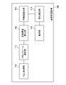
- FIG. 40 shows an example of a functional block diagram of the image processing apparatus 100 of this embodiment.
- the image processing apparatus 100 includes a query acquisition unit 109, a query frame selection unit 112, a skeleton structure detection unit 102, a feature amount calculation unit 103, a change calculation unit 110, and a search unit 111.
- the image processing apparatus 100 may further include other functional units described in the first and second embodiments.
- An example of the hardware configuration of the image processing apparatus 100 of this embodiment is the same as that of the first and second embodiments.
- the query acquisition unit 109 acquires a query video made up of a plurality of time-series first frame images. For example, the query acquisition unit 109 acquires a query moving image (moving image file) input/designated/selected by user operation.
- a query moving image moving image file
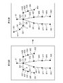
- the query frame selection unit 112 selects at least part of the plurality of first frame images as query frames. As shown in FIGS. 41 and 42, the query frame selection unit 112 can intermittently select query frames from a plurality of time-series first frame images included in the query moving image. The number of first frame images between query frames may be constant or may be random. The query frame selection unit 112 can execute, for example, any one of the following selection processes 1 to 3.
- the query frame selection unit 112 selects a query frame based on user input. That is, the user makes an input designating at least part of the plurality of first frame images as the query frame. Then, the query frame selection unit 112 selects the first frame image specified by the user as the query frame.
- the query frame selection unit 112 selects a query frame according to a predetermined rule.
- the query frame selection unit 112 selects multiple query frames from multiple first frame images at predetermined regular intervals. That is, the query frame selection unit 112 selects a query frame every M frames. Examples of M include 2 or more and 10 or less, but are not limited thereto. M may be predetermined or may be selected by the user.
- the query frame selection unit 112 selects a query frame according to a predetermined rule.
- the query frame selection unit 112 selects one query frame, and then selects between the query frame and each of the first frame images after the query frame in chronological order. Calculate the similarity of Similarity is the same concept as in the first and second embodiments. Then, the query frame selection unit 112 selects, as a new query frame, the first frame image whose similarity is equal to or lower than the reference value and whose chronological order is the earliest.
- the query frame selection unit 112 calculates the degree of similarity between the newly selected query frame and each of the first frame images following the query frame in chronological order. Then, the query frame selection unit 112 selects, as a new query frame, the first frame image whose similarity is equal to or lower than the reference value and whose chronological order is the earliest.
- the query frame selection unit 112 selects a query frame by repeating the process. According to this process, the poses of persons included in adjacent query frames are different to some extent. Therefore, it is possible to select a plurality of query frames showing a characteristic posture of a person while suppressing an increase in the number of query frames.
- the reference value may be predetermined, may be selected by the user, or may be set by other means.
- the skeletal structure detection unit 102 detects key points of a person (object) included in each of a plurality of first frame images.
- the skeletal structure detection unit 102 may subject only the query frame to the detection process, or may subject all the first frame images to the detection process.
- the configuration of the skeletal structure detection unit 102 is the same as in Embodiments 1 and 2, so detailed description thereof will be omitted here.
- the feature amount calculation unit 103 calculates the feature amount of the detected keypoint, that is, the feature amount of the detected two-dimensional skeleton structure for each first frame image.
- the feature amount calculation unit 103 may subject only the query frame to the calculation process, or may subject all the first frame images to the calculation process. Since the configuration of the feature amount calculation unit 103 is the same as that of the first and second embodiments, detailed description thereof is omitted here.
- the change calculation unit 110 calculates the direction of change of the feature amount along the time axis of the plurality of time-series first frame images.
- the change calculation unit 110 calculates, for example, the direction of change in feature quantity between adjacent query frames.
- the feature amount is the feature amount calculated by the feature amount calculation unit 103 .
- the feature quantity is the height, area, etc. of the skeleton region, and is expressed numerically.
- the direction in which the feature amount changes is divided into three directions, for example, "the direction in which the numerical value increases", “the direction in which the numerical value does not change", and "the direction in which the numerical value decreases”. “No numerical value change” may be a case where the absolute value of the amount of change in the feature amount is 0, or a case where the absolute value of the amount of change in the feature amount is equal to or less than the threshold.
- the change calculation unit 110 can calculate time-series data indicating a time-series change in the direction of change in the feature amount.
- the time-series data is, for example, "direction of increasing numerical value” ⁇ "direction of increasing numerical value” ⁇ “direction of increasing numerical value” ⁇ “no change in numerical value” ⁇ “no change in numerical value” ⁇ “higher numerical value direction”.
- “the direction in which the numerical value increases” is expressed as "1”
- “no change in the numerical value” is expressed as "0”
- the direction in which the numerical value decreases” is expressed as "-1”.
- 111001" can be represented by a numerical string.
- the change calculation unit 110 can calculate the direction of change in the feature amount between the two images.
- the search unit 111 searches for moving images using the direction of change in the feature amount calculated by the change calculation unit 110 as a key. Specifically, the search unit 111 searches for a DB video that matches the key from videos stored in the database 201 (hereinafter referred to as DB videos).
- the search unit 111 can execute, for example, one of the following video search processes 1 and 2.
- the search unit 111 can search for DB moving images whose similarity of the time-series data is equal to or higher than a reference value.
- a method for calculating the degree of similarity of time-series data is not particularly limited, and any technique can be adopted.
- time-series data may be created in advance by the same method as described above corresponding to each DB moving image stored in the database 201 and stored in the database.
- the search unit 111 may process each DB moving image stored in the database 201 in the same manner as described above each time a search process is performed, and create the time-series data for each DB moving image.
- the search unit 111 can search for DB moving images indicating the direction of change in the feature amount.
- index data of the direction of change of the feature amount shown in each DB moving image may be created in advance corresponding to each DB moving image stored in the database 201 and stored in the database.
- the search unit 111 processes each of the DB moving images stored in the database 201 in the same manner as described above each time a search process is performed, and determines the direction of change in the feature quantity indicated in each DB moving image for each DB moving image. index data may be created.
- FIG. 1 An example of the processing flow of the image processing apparatus 100 will be described using FIG. The purpose here is to explain the flow of processing. Since the details of each process have been described above, descriptions thereof are omitted here.
- the image processing apparatus 100 acquires a query moving image composed of a plurality of time-series first frame images (S400), it selects at least part of the plurality of first frame images as a query frame (S401).
- the image processing apparatus 100 detects keypoints of objects included in each of the plurality of first frame images (S402). Note that only the query frame selected in S401 may be subject to the processing, or all first frame images may be subject to the processing.
- the image processing apparatus 100 calculates feature amounts of the detected keypoints for each of the plurality of first frame images (S403). Note that only the query frame selected in S401 may be subject to the processing, or all first frame images may be subject to the processing.
- the image processing apparatus 100 calculates the direction of change of the feature amount along the time axis of the plurality of time-series first frame images (S404).
- the image processing apparatus 100 calculates the direction of change in feature amount between adjacent query frames.
- the direction of change is divided into, for example, three directions, namely, "direction of increase in numerical value", “direction of no change in numerical value”, and "direction of decreasing numerical value”.
- the image processing device 100 can calculate time-series data indicating a time-series change in the direction of change in the feature amount.
- the image processing apparatus 100 can calculate the direction of change in feature amount between the two images.
- the image processing apparatus 100 searches for DB moving images using the change direction of the feature amount calculated in S404 as a key (S405). Specifically, the image processing apparatus 100 searches for a DB moving image that matches the key from among the DB moving images stored in the database 201 . The image processing apparatus 100 then outputs the search result.
- the output of search results can be realized by adopting any technology.
- the image processing apparatus 100 of the present embodiment can be configured to employ one or more of Modifications 1 to 7 below.
- the image processing device 100 may not have the query frame selection unit 112 .
- the change calculator 110 can calculate the direction of change in the feature amount between adjacent first frame images.
- the change calculation unit 110 can calculate time-series data indicating a time-series change in the direction of change in the feature amount.
- the change calculation unit 110 can calculate the direction of change in feature amount between the two images.
- FIG. 1 An example of the processing flow of the image processing apparatus 100 in the modification will be described using FIG.
- the purpose here is to explain the flow of processing. Since the details of each process have been described above, descriptions thereof are omitted here.
- the image processing device 100 acquires a query moving image composed of a plurality of time-series first frame images (S300). Next, the image processing apparatus 100 detects keypoints of objects included in each of the plurality of first frame images (S301). Next, the image processing apparatus 100 calculates feature amounts of the detected keypoints for each of the plurality of first frame images (S302).
- the image processing apparatus 100 calculates the direction of change of the feature amount along the time axis of the plurality of time-series first frame images (S303). Specifically, the image processing apparatus 100 calculates the direction of change in feature amount between adjacent first frame images.
- the image processing apparatus 100 searches for DB moving images using the direction of change in the feature amount calculated in S303 as a key (S304). Specifically, the image processing apparatus 100 searches for a DB moving image that matches the key from among the DB moving images stored in the database 201 . The image processing apparatus 100 then outputs the search result.
- the output of search results can be realized by adopting any technology.
- the image processing apparatus 100 detects key points of a person's body, and searches DB moving images using the direction of change as a key.
- the image processing apparatus 100 can detect a key point of an object other than a person, and search DB moving images using the direction of change as a key.
- Objects are not particularly limited, and examples thereof include animals, plants, natural products, artificial objects, and the like.
- the change calculation unit 110 can calculate the magnitude of change in the feature amount in addition to the direction of change in the feature amount.
- the change calculation unit 110 can calculate the magnitude of change in feature quantity between adjacent query frames or between adjacent first frame images.
- the magnitude of change in the feature amount can be represented, for example, by the absolute value of the difference between the numerical values indicating the feature amount.
- the magnitude of change in feature amount may be a value obtained by normalizing the absolute value.
- the change calculation unit 110 calculates a time series that further indicates a time-series change in the magnitude of change in addition to the direction of change in the feature amount. Data can be calculated.
- the change calculation unit 110 can calculate the direction and magnitude of the change in feature amount between the two images.
- the search unit 111 searches the DB video using the change direction and change magnitude calculated by the change calculation unit 110 as keys.
- the search unit 111 can search for DB videos whose similarity of the time-series data is equal to or higher than the reference value.
- a method for calculating the degree of similarity of time-series data is not particularly limited, and any technique can be adopted.
- the search unit 111 retrieves the DB animation showing the direction and magnitude of change in the feature amount. can be searched.
- the change calculation unit 110 can calculate the speed of change of the feature amount in addition to the direction of change of the feature amount.
- This modified example is effective when query frames are selected at random intervals from the first frame image as shown in FIG. 42 and the direction of change in feature amount between adjacent query frames is calculated. In this case, it is possible to search for more similar DB moving images by referring to the speed of change in the feature amount between adjacent query frames.
- the change calculation unit 110 can calculate the speed of change in feature values between adjacent query frames.
- the speed can be calculated by dividing the amount of change in the feature amount by a value indicating the amount of time between adjacent query frames (the number of frames, a value converted into time based on the frame rate, etc.).
- the magnitude of change in the feature amount can be represented, for example, by the absolute value of the difference between the numerical values indicating the feature amount.
- the magnitude of change in feature amount may be a value obtained by normalizing the absolute value.
- the change calculation unit 110 can calculate time-series data that further indicates the speed of change in addition to the direction of change of the feature amount.
- the change calculation unit 110 can calculate the direction and speed of changes in feature amounts between the two images.
- the search unit 111 searches the DB video using the change direction and change speed calculated by the change calculation unit 110 as keys.
- the search unit 111 can search for DB videos whose similarity of the time-series data is equal to or higher than the reference value.
- a method for calculating the degree of similarity of time-series data is not particularly limited, and any technique can be adopted.
- the search unit 111 can search the DB video showing the direction and speed of change in the feature amount.
- the search unit 111 has searched for a DB moving image that matches the key, but may search for a DB moving image that does not match the key. That is, the search unit 111 may search for a DB moving image whose degree of similarity to the time-series data, which is the key, is less than a reference value. Further, the search unit 111 may search for a DB moving image that does not include the direction of change of the key feature amount (which may include magnitude, speed, etc.).
- the search unit 111 may search for DB moving images that match search conditions in which a plurality of keys are connected by arbitrary logical operators.
- the search unit 111 further extracts representative images selected from the first frame images of the query video. It can be used as a key to search DB videos.
- the number of representative images may be one or plural.
- the query frame may be used as the representative image, a frame selected from the query frames by arbitrary means may be used as the representative image, or the representative image may be selected from the first frame images by other means. .
- the search unit 111 calculates the degree of similarity between the DB moving image stored in the database 201 and the query moving image calculated based on the representative image, and the result calculated by the change calculating unit 110 (the direction of change in the special amount, A DB moving image having a total similarity equal to or greater than a reference value, which is obtained by integrating the similarity with the query moving image calculated based on the size, speed, etc., can be retrieved.
- the search unit 111 can calculate the degree of similarity between each DB moving image and the query moving image based on the following criteria.
- the degree of similarity between the representative image and the frame image is calculated based on the posture of the person included in each image. The more similar the poses are, the higher the degree of similarity between the representative image and the frame image.
- the search unit 111 may calculate the degree of similarity of the feature amount of the skeletal structure described in the above embodiment, or use other well-known techniques to calculate the posture of the person. may be calculated.
- the similarity of the time-series data is the similarity between each DB video and the query video.
- the direction of change is the same as that of the query video, and the magnitude and speed of change are shown in the query video. , the similarity of the DB moving image is increased.
- each degree of similarity may be normalized and summed up.
- each degree of similarity may be weighted. That is, the similarity based on the representative image or the value obtained by multiplying the standard value thereof by a predetermined weighting factor, and the similarity based on the result calculated by the change calculation unit 110 (the direction, magnitude, speed, etc. of change in the characteristic amount)
- a value obtained by multiplying the degree or its standard value by a predetermined weighting factor may be calculated as the integration result.
- the image processing apparatus 100 may configure the image processing system 1 together with the camera 200 and database 201 .
- the same effects as those of the first and second embodiments are realized. Further, according to the image processing apparatus 100 of the present embodiment, it is possible to search for moving images using the direction of change in the orientation of an object included in an image, the magnitude of change, the speed of change, and the like as keys. According to the image processing apparatus 100 of this embodiment, it is possible to accurately search for a moving image including a desired scene.
- query acquisition means for acquiring a plurality of time-series first frame images; skeleton structure detection means for detecting key points of an object included in each of the plurality of first frame images; feature quantity calculation means for calculating a feature quantity of the detected key point for each of the first frame images; change calculation means for calculating a direction of change of the feature amount along the time axis of the plurality of time-series first frame images; a search means for searching for a moving image using the calculated direction of change in the feature amount as a key; An image processing device having 2. The change calculation means further calculates the magnitude of the change, 2.
- the image processing apparatus according to 1, wherein the searching means searches for moving images further using the calculated magnitude of change as a key. 3.
- the change calculation means further calculates the speed of the change, 3.
- the image processing apparatus according to 1 or 2 wherein the searching means searches moving images further using the calculated speed of change as a key. 4.
- 4. The image processing apparatus according to any one of 1 to 3, wherein the searching means searches for a moving image further using a representative image among the plurality of first frame images as a key. 5.
- the computer a query acquisition step of acquiring a plurality of time-series first frame images; a skeletal structure detection step of detecting key points of an object included in each of the plurality of first frame images; a feature quantity calculation step of calculating a feature quantity of the detected key point for each of the first frame images; a change calculation step of calculating a direction of change of the feature amount along the time axis of the plurality of time-series first frame images; a search step of searching for a moving image using the calculated direction of change in the feature quantity as a key; An image processing method that performs 7.
- query acquisition means for acquiring a plurality of time-series first frame images
- Skeletal structure detection means for detecting key points of an object included in each of the plurality of first frame images
- feature quantity calculation means for calculating a feature quantity of the detected key point for each of the first frame images
- change calculation means for calculating a direction of change of the feature amount along the time axis of the plurality of time-series first frame images
- search means for searching for a moving image using the calculated direction of change in the feature amount as a key
- a program that acts as a
- image processing system 10 image processing device 11 skeleton detection unit 12 feature quantity calculation unit 13 recognition unit 100 image processing device 101 image acquisition unit 102 skeleton structure detection unit 103 feature quantity calculation unit 104 classification unit 105 search unit 106 input unit 107 display unit 108 height calculation unit 109 query acquisition unit 110 change calculation unit 111 search unit 112 query frame selection unit 200 camera 201 database 300, 301 human body model 401 two-dimensional skeletal structure
Abstract
本発明は、時系列な複数の第1フレーム画像を取得するクエリ取得部(109)と、複数の第1フレーム画像各々に含まれる物体のキーポイントを検出する骨格構造検出部(102)と、第1フレーム画像毎に、検出されたキーポイントの特徴量を算出する特徴量算出部(103)と、時系列な複数の第1フレーム画像の時間軸に沿った特徴量の変化の方向を算出する変化算出部(110)と、算出された特徴量の変化の方向をキーとして用いて動画を検索する検索部(111)と、を有する画像処理装置(100)を提供する。
Description
本発明は、画像処理装置、画像処理方法、およびプログラムに関する。
近年、監視システム等において、監視カメラの画像から人物の姿勢や行動等の状態の検出や検索を行う技術が利用されている。関連する技術として、例えば、特許文献1及び2が知られている。特許文献1には、深さ映像に含まれる人物の頭や手足等のキージョイントに基づいて、類似する人物の姿勢を検索する技術が開示されている。特許文献2には、人物の姿勢と関連しないが、画像に付加された傾き等の姿勢情報を利用して類似画像を検索する技術が開示されている。なお、その他に、人物の骨格推定に関連する技術として、非特許文献1が知られている。
一方、近年は動画をクエリとして利用し、このクエリに類似する動画を検索することも検討されている。例えば特許文献3には、クエリとなる参照映像を入力すると、登場人物の顔の数、並びに各登場人物の顔の位置、大きさ、及び向きを用いて、類似する映像を検索することが記載されている。
Zhe Cao, Tomas Simon, Shih-En Wei, Yaser Sheikh, "Realtime Multi-Person 2D Pose Estimation using Part Affinity Fields", The IEEE Conference on Computer Vision and Pattern Recognition (CVPR), 2017, P. 7291-7299
所望のシーンを含む動画を検索する処理の検索精度を上げることは難しい。本発明の目的の一つは、所望のシーンを含む動画を検索する処理の検索精度を上げることにある。
本発明によれば、
時系列な複数の第1フレーム画像を取得するクエリ取得手段と、
複数の前記第1フレーム画像各々に含まれる物体のキーポイントを検出する骨格構造検出手段と、
前記第1フレーム画像毎に、検出された前記キーポイントの特徴量を算出する特徴量算出手段と、
時系列な複数の前記第1フレーム画像の時間軸に沿った前記特徴量の変化の方向を算出する変化算出手段と、
算出された前記特徴量の変化の方向をキーとして用いて動画を検索する検索手段と、
を有する画像処理装置が提供される。
時系列な複数の第1フレーム画像を取得するクエリ取得手段と、
複数の前記第1フレーム画像各々に含まれる物体のキーポイントを検出する骨格構造検出手段と、
前記第1フレーム画像毎に、検出された前記キーポイントの特徴量を算出する特徴量算出手段と、
時系列な複数の前記第1フレーム画像の時間軸に沿った前記特徴量の変化の方向を算出する変化算出手段と、
算出された前記特徴量の変化の方向をキーとして用いて動画を検索する検索手段と、
を有する画像処理装置が提供される。
また、本発明によれば、
コンピュータが、
時系列な複数の第1フレーム画像を取得するクエリ取得工程と、
複数の前記第1フレーム画像各々に含まれる物体のキーポイントを検出する骨格構造検出工程と、
前記第1フレーム画像毎に、検出された前記キーポイントの特徴量を算出する特徴量算出工程と、
時系列な複数の前記第1フレーム画像の時間軸に沿った前記特徴量の変化の方向を算出する変化算出工程と、
算出された前記特徴量の変化の方向をキーとして用いて動画を検索する検索工程と、
を実行する画像処理方法が提供される。
コンピュータが、
時系列な複数の第1フレーム画像を取得するクエリ取得工程と、
複数の前記第1フレーム画像各々に含まれる物体のキーポイントを検出する骨格構造検出工程と、
前記第1フレーム画像毎に、検出された前記キーポイントの特徴量を算出する特徴量算出工程と、
時系列な複数の前記第1フレーム画像の時間軸に沿った前記特徴量の変化の方向を算出する変化算出工程と、
算出された前記特徴量の変化の方向をキーとして用いて動画を検索する検索工程と、
を実行する画像処理方法が提供される。
また、本発明によれば、
コンピュータを、
時系列な複数の第1フレーム画像を取得するクエリ取得手段、
複数の前記第1フレーム画像各々に含まれる物体のキーポイントを検出する骨格構造検出手段、
前記第1フレーム画像毎に、検出された前記キーポイントの特徴量を算出する特徴量算出手段、
時系列な複数の前記第1フレーム画像の時間軸に沿った前記特徴量の変化の方向を算出する変化算出手段、及び、
算出された前記特徴量の変化の方向をキーとして用いて動画を検索する検索手段、
として機能させるプログラムが提供される。
コンピュータを、
時系列な複数の第1フレーム画像を取得するクエリ取得手段、
複数の前記第1フレーム画像各々に含まれる物体のキーポイントを検出する骨格構造検出手段、
前記第1フレーム画像毎に、検出された前記キーポイントの特徴量を算出する特徴量算出手段、
時系列な複数の前記第1フレーム画像の時間軸に沿った前記特徴量の変化の方向を算出する変化算出手段、及び、
算出された前記特徴量の変化の方向をキーとして用いて動画を検索する検索手段、
として機能させるプログラムが提供される。
本発明によれば、所望のシーンを含む動画を検索する処理の検索精度を上げることができる。
上述した目的、およびその他の目的、特徴および利点は、以下に述べる公的な実施の形態、およびそれに付随する以下の図面によってさらに明らかになる。
実施の形態に係る画像処理装置の概要を示す構成図である。
実施の形態1に係る画像処理装置の構成を示す構成図である。
実施の形態1に係る画像処理方法を示すフローチャートである。
実施の形態1に係る分類方法を示すフローチャートである。
実施の形態1に係る検索方法を示すフローチャートである。
実施の形態1に係る骨格構造の検出例を示す図である。
実施の形態1に係る人体モデルを示す図である。
実施の形態1に係る骨格構造の検出例を示す図である。
実施の形態1に係る骨格構造の検出例を示す図である。
実施の形態1に係る骨格構造の検出例を示す図である。
実施の形態1に係る分類方法の具体例を示すグラフである。
実施の形態1に係る分類結果の表示例を示す図である。
実施の形態1に係る検索方法を説明するための図である。
実施の形態1に係る検索方法を説明するための図である。
実施の形態1に係る検索方法を説明するための図である。
実施の形態1に係る検索方法を説明するための図である。
実施の形態1に係る検索結果の表示例を示す図である。
実施の形態2に係る画像処理装置の構成を示す構成図である。
実施の形態2に係る画像処理方法を示すフローチャートである。
実施の形態2に係る身長画素数算出方法の具体例1を示すフローチャートである。
実施の形態2に係る身長画素数算出方法の具体例2を示すフローチャートである。
実施の形態2に係る身長画素数算出方法の具体例2を示すフローチャートである。
実施の形態2に係る正規化方法を示すフローチャートである。
実施の形態2に係る人体モデルを示す図である。
実施の形態2に係る骨格構造の検出例を示す図である。
実施の形態2に係る骨格構造の検出例を示す図である。
実施の形態2に係る骨格構造の検出例を示す図である。
実施の形態2に係る人体モデルを示す図である。
実施の形態2に係る骨格構造の検出例を示す図である。
実施の形態2に係る身長画素数算出方法を説明するためのヒストグラムである。
実施の形態2に係る骨格構造の検出例を示す図である。
実施の形態2に係る3次元人体モデルを示す図である。
実施の形態2に係る身長画素数算出方法を説明するための図である。
実施の形態2に係る身長画素数算出方法を説明するための図である。
実施の形態2に係る身長画素数算出方法を説明するための図である。
実施の形態2に係る正規化方法を説明するための図である。
実施の形態2に係る正規化方法を説明するための図である。
実施の形態2に係る正規化方法を説明するための図である。
画像処理装置のハードウェア構成例を示す図である。
実施の形態3に係る画像処理装置の構成を示す構成図である。
実施の形態3に係るクエリフレーム選択処理を説明するための図である。
実施の形態3に係るクエリフレーム選択処理を説明するための図である。
実施の形態3に係る特徴量の変化の方向の算出処理を説明するための図である。
実施の形態3に係る画像処理装置の処理の流れの一例を示すフローチャートである。
実施の形態3に係る画像処理装置の構成を示す構成図である。
実施の形態3に係る画像処理装置の処理の流れの一例を示すフローチャートである。
以下、本発明の実施の形態について、図面を用いて説明する。尚、すべての図面において、同様な構成要素には同様の符号を付し、適宜説明を省略する。
(実施の形態に至る検討)
近年、ディープラーニング等の機械学習を活用した画像認識技術が様々なシステムに応用されている。例えば、監視カメラの画像により監視を行う監視システムへの適用が進められている。監視システムに機械学習を活用することで、画像から人物の姿勢や行動等の状態をある程度把握することが可能とされつつある。
近年、ディープラーニング等の機械学習を活用した画像認識技術が様々なシステムに応用されている。例えば、監視カメラの画像により監視を行う監視システムへの適用が進められている。監視システムに機械学習を活用することで、画像から人物の姿勢や行動等の状態をある程度把握することが可能とされつつある。
しかしながら、このような関連する技術では、必ずしもオンデマンドにユーザが望む人物の状態を把握できない場合がある。例えば、ユーザが検索し把握したい人物の状態を事前に特定できている場合もあれば、未知の状態のように具体的に特定できていない場合もある。そうすると、場合によっては、ユーザが検索したい人物の状態を詳細に指定することができない。また、人物の体の一部が隠れているような場合には検索等を行うことができない。関連する技術では、特定の検索条件のみからしか人物の状態を検索できないため、所望の人物の状態を柔軟に検索や分類することが困難である。
そこで、発明者らは、オンデマンドに画像からユーザ所望の人物の状態を認識するため、非特許文献1などの骨格推定技術を利用する方法を検討した。非特許文献1に開示されたOpenPose等のように、関連する骨格推定技術では、様々なパターンの正解付けされた画像データを学習することで、人物の骨格を推定する。以下の実施の形態では、このような骨格推定技術を活用することで、人物の状態を柔軟に認識することを可能とする。
なお、OpenPose等の骨格推定技術により推定される骨格構造は、関節等の特徴的な点である「キーポイント」と、キーポイント間のリンクを示す「ボーン(ボーンリンク)」とから構成される。このため、以下の実施の形態では、骨格構造について「キーポイント」と「ボーン」という用語を用いて説明するが、特に限定されない限り、「キーポイント」は人物の「関節」に対応し、「ボーン」は人物の「骨」に対応している。
(実施の形態の概要)
図1は、実施の形態に係る画像処理装置10の概要を示している。図1に示すように、画像処理装置10は、骨格検出部11、特徴量算出部12、及び認識部13を備えている。骨格検出部11は、カメラ等から取得される2次元画像に基づいて、複数の人物の2次元骨格構造を検出する。特徴量算出部12は、骨格検出部11により検出された複数の2次元骨格構造の特徴量を算出する。認識部13は、特徴量算出部12により算出された複数の特徴量の類似度に基づいて、複数の人物の状態の認識処理を行う。認識処理は、人物の状態の分類処理や検索処理等である。
図1は、実施の形態に係る画像処理装置10の概要を示している。図1に示すように、画像処理装置10は、骨格検出部11、特徴量算出部12、及び認識部13を備えている。骨格検出部11は、カメラ等から取得される2次元画像に基づいて、複数の人物の2次元骨格構造を検出する。特徴量算出部12は、骨格検出部11により検出された複数の2次元骨格構造の特徴量を算出する。認識部13は、特徴量算出部12により算出された複数の特徴量の類似度に基づいて、複数の人物の状態の認識処理を行う。認識処理は、人物の状態の分類処理や検索処理等である。
このように、実施の形態では、2次元画像から人物の2次元骨格構造を検出し、この2次元骨格構造から算出される特徴量に基づいて人物の状態の分類や検索等の認識処理を行うことで、所望の人物の状態を柔軟に認識することができる。
(実施の形態1)
以下、図面を参照して実施の形態1について説明する。図2は、本実施の形態に係る画像処理装置100の構成を示している。画像処理装置100は、カメラ200及びデータベース(DB)201とともに画像処理システム1を構成する。画像処理装置100を含む画像処理システム1は、画像から推定される人物の骨格構造に基づき、人物の姿勢や行動等の状態を分類及び検索するシステムである。
以下、図面を参照して実施の形態1について説明する。図2は、本実施の形態に係る画像処理装置100の構成を示している。画像処理装置100は、カメラ200及びデータベース(DB)201とともに画像処理システム1を構成する。画像処理装置100を含む画像処理システム1は、画像から推定される人物の骨格構造に基づき、人物の姿勢や行動等の状態を分類及び検索するシステムである。
カメラ200は、2次元の画像を生成する監視カメラ等の撮像部である。カメラ200は、所定の箇所に設置されて、設置箇所から撮像領域における人物等を撮像する。カメラ200は、撮像した画像(映像)を画像処理装置100へ出力可能に直接接続、もしくはネットワーク等を介して接続されている。なお、カメラ200を画像処理装置100の内部に設けてもよい。
データベース201は、画像処理装置100の処理に必要な情報(データ)や処理結果等を格納するデータベースである。データベース201は、画像取得部101が取得した画像や、骨格構造検出部102の検出結果、機械学習用のデータ、特徴量算出部103が算出した特徴量、分類部104の分類結果、検索部105の検索結果等を記憶する。データベース201は、画像処理装置100と必要に応じてデータを入出力可能に直接接続、もしくはネットワーク等を介して接続されている。なお、データベース201をフラッシュメモリなどの不揮発性メモリやハードディスク装置等として、画像処理装置100の内部に設けてもよい。
図2に示すように、画像処理装置100は、画像取得部101、骨格構造検出部102、特徴量算出部103、分類部104、検索部105、入力部106、及び表示部107を備えている。なお、各部(ブロック)の構成は一例であり、後述の方法(動作)が可能であれば、その他の各部で構成されてもよい。また、画像処理装置100は、例えば、プログラムを実行するパーソナルコンピュータやサーバ等のコンピュータ装置で実現されるが、1つの装置で実現してもよいし、ネットワーク上の複数の装置で実現してもよい。例えば、入力部106や表示部107等を外部の装置としてもよい。また、分類部104及び検索部105の両方を備えていてもよいし、いずれか一方のみを備えていてもよい。分類部104及び検索部105の両方、もしくは一方は、人物の状態の認識処理を行う認識部である。
画像取得部101は、カメラ200が撮像した人物を含む2次元の画像を取得する。画像取得部101は、例えば、所定の監視期間にカメラ200が撮像した、人物を含む画像(複数の画像を含む映像)を取得する。なお、カメラ200からの取得に限らず、予め用意された人物を含む画像をデータベース201等から取得してもよい。
骨格構造検出部102は、取得された2次元の画像に基づき、画像内の人物の2次元の骨格構造を検出する。骨格構造検出部102は、取得された画像の中で認識される全ての人物について、骨格構造を検出する。骨格構造検出部102は、機械学習を用いた骨格推定技術を用いて、認識される人物の関節等の特徴に基づき人物の骨格構造を検出する。骨格構造検出部102は、例えば、非特許文献1のOpenPose等の骨格推定技術を用いる。
特徴量算出部103は、検出された2次元の骨格構造の特徴量を算出し、算出した特徴量を、処理対象となった画像に紐づけてデータベース201に格納する。骨格構造の特徴量は、人物の骨格の特徴を示しており、人物の骨格に基づいて人物の状態を分類や検索するための要素となる。通常、この特徴量は、複数のパラメータ(例えば後述する分類要素)を含んでいる。そして特徴量は、骨格構造の全体の特徴量でもよいし、骨格構造の一部の特徴量でもよく、骨格構造の各部のように複数の特徴量を含んでもよい。特徴量の算出方法は、機械学習や正規化等の任意の方法でよく、正規化として最小値や最大値を求めてもよい。一例として、特徴量は、骨格構造を機械学習することで得られた特徴量や、骨格構造の頭部から足部までの画像上の大きさ等である。骨格構造の大きさは、画像上の骨格構造を含む骨格領域の上下方向の高さや面積等である。上下方向(高さ方向または縦方向)は、画像における上下の方向(Y軸方向)であり、例えば、地面(基準面)に対し垂直な方向である。また、左右方向(横方向)は、画像における左右の方向(X軸方向)であり、例えば、地面に対し平行な方向である。
なお、ユーザが望む分類や検索を行うためには、分類や検索処理に対しロバスト性を有する特徴量を用いることが好ましい。例えば、ユーザが、人物の向きや体型に依存しない分類や検索を望む場合、人物の向きや体型にロバストな特徴量を使用してもよい。同じ姿勢で様々な方向に向いている人物の骨格や同じ姿勢で様々な体型の人物の骨格を学習することや、骨格の上下方向のみの特徴を抽出することで、人物の向きや体型に依存しない特徴量を得ることができる。
分類部104は、データベース201に格納された複数の骨格構造を、骨格構造の特徴量の類似度に基づいて分類する(クラスタリングする)。分類部104は、人物の状態の認識処理として、骨格構造の特徴量に基づいて複数の人物の状態を分類しているとも言える。類似度は、骨格構造の特徴量間の距離である。分類部104は、骨格構造の全体の特徴量の類似度により分類してもよいし、骨格構造の一部の特徴量の類似度により分類してもよく、骨格構造の第1の部分(例えば両手)及び第2の部分(例えば両足)の特徴量の類似度により分類してもよい。なお、各画像における人物の骨格構造の特徴量に基づいて人物の姿勢を分類してもよいし、時系列に連続する複数の画像における人物の骨格構造の特徴量の変化に基づいて人物の行動を分類してもよい。すなわち、分類部104は、骨格構造の特徴量に基づいて人物の姿勢や行動を含む人物の状態を分類できる。例えば、分類部104は、所定の監視期間に撮像された複数の画像における複数の骨格構造を分類対象とする。分類部104は、分類対象の特徴量間の類似度を求め、類似度の高い骨格構造が同じクラスタ(似た姿勢のグループ)となるように分類する。なお、検索と同様に、分類条件をユーザが指定できるようにしてもよい。分類部104は、骨格構造の分類結果をデータベース201に格納するとともに、表示部107に表示する。
検索部105は、データベース201に格納された複数の骨格構造の中から、検索クエリ(クエリ状態)の特徴量と類似度の高い骨格構造を検索する。検索部105は、人物の状態の認識処理として、骨格構造の特徴量に基づいて複数の人物の状態の中から、検索条件(クエリ状態)に該当する人物の状態を検索しているとも言える。分類と同様に、類似度は、骨格構造の特徴量間の距離である。検索部105は、骨格構造の全体の特徴量の類似度により検索してもよいし、骨格構造の一部の特徴量の類似度により検索してもよく、骨格構造の第1の部分(例えば両手)及び第2の部分(例えば両足)の特徴量の類似度により検索してもよい。なお、各画像における人物の骨格構造の特徴量に基づいて人物の姿勢を検索してもよいし、時系列に連続する複数の画像における人物の骨格構造の特徴量の変化に基づいて人物の行動を検索してもよい。すなわち、検索部105は、骨格構造の特徴量に基づいて人物の姿勢や行動を含む人物の状態を検索できる。例えば、検索部105は、分類対象と同様に、所定の監視期間に撮像された複数の画像における複数の骨格構造の特徴量を検索対象とする。また、分類部104が表示した分類結果の中からユーザが指定した骨格構造(姿勢)を検索クエリ(検索キー)とする。なお、分類結果に限らず、分類されていない複数の骨格構造の中から検索クエリを選択してもよいし、検索クエリとなる骨格構造をユーザが入力してもよい。検索部105は、検索対象の特徴量の中から、検索クエリの骨格構造の特徴量と類似度の高い特徴量を検索する。検索部105は、特徴量の検索結果をデータベース201に格納するとともに、表示部107に表示する。
入力部106は、画像処理装置100を操作するユーザから入力された情報を取得する入力インタフェースである。例えば、ユーザは、監視カメラの画像から不審な状態の人物を監視する監視者である。入力部106は、例えば、GUI(Graphical User Interface)であり、キーボードやマウス、タッチパネル等の入力装置から、ユーザの操作に応じた情報が入力される。例えば、入力部106は、分類部104により分類された骨格構造(姿勢)の中から、指定された人物の骨格構造を検索クエリとして受け付ける。
表示部107は、画像処理装置100の動作(処理)の結果等を表示する表示部であり、例えば、液晶ディスプレイや有機EL(Electro Luminescence)ディスプレイ等のディスプレイ装置である。表示部107は、分類部104の分類結果や検索部105の検索結果を類似度等に応じてGUIに表示する。
図39は、画像処理装置100のハードウェア構成例を示す図である。画像処理装置100は、バス1010、プロセッサ1020、メモリ1030、ストレージデバイス1040、入出力インタフェース1050、及びネットワークインタフェース1060を有する。
バス1010は、プロセッサ1020、メモリ1030、ストレージデバイス1040、入出力インタフェース1050、及びネットワークインタフェース1060が、相互にデータを送受信するためのデータ伝送路である。ただし、プロセッサ1020などを互いに接続する方法は、バス接続に限定されない。
プロセッサ1020は、CPU(Central Processing Unit) やGPU(Graphics Processing Unit)などで実現されるプロセッサである。
メモリ1030は、RAM(Random Access Memory)などで実現される主記憶装置である。
ストレージデバイス1040は、HDD(Hard Disk Drive)、SSD(Solid State Drive)、メモリカード、又はROM(Read Only Memory)などで実現される補助記憶装置である。ストレージデバイス1040は画像処理装置100の各機能(例えば画像取得部101、骨格構造検出部102、特徴量算出部103、分類部104、検索部105、及び入力部106)を実現するプログラムモジュールを記憶している。プロセッサ1020がこれら各プログラムモジュールをメモリ1030上に読み込んで実行することで、そのプログラムモジュールに対応する各機能が実現される。また、ストレージデバイス1040はデータベース201としても機能することもある。
入出力インタフェース1050は、画像処理装置100と各種入出力機器とを接続するためのインタフェースである。データベース201が画像処理装置100の外部に位置する場合、画像処理装置100は、入出力インタフェース1050を介してデータベース201と接続してもよい。
ネットワークインタフェース1060は、画像処理装置100をネットワークに接続するためのインタフェースである。このネットワークは、例えばLAN(Local Area Network)やWAN(Wide Area Network)である。ネットワークインタフェース1060がネットワークに接続する方法は、無線接続であってもよいし、有線接続であってもよい。画像処理装置100は、ネットワークインタフェース1060を介してカメラ200と通信してもよい。データベース201が画像処理装置100の外部に位置する場合、画像処理装置100は、ネットワークインタフェース1060を介してデータベース201と接続してもよい。
図3~図5は、本実施の形態に係る画像処理装置100の動作を示している。図3は、画像処理装置100における画像取得から検索処理までの流れを示し、図4は、図3の分類処理(S104)の流れを示し、図5は、図3の検索処理(S105)の流れを示している。
図3に示すように、画像処理装置100は、カメラ200から画像を取得する(S101)。画像取得部101は、骨格構造から分類や検索を行うために人物を撮像した画像を取得し、取得した画像をデータベース201に格納する。画像取得部101は、例えば、所定の監視期間に撮像された複数の画像を取得し、複数の画像に含まれる全ての人物について以降の処理を行う。
続いて、画像処理装置100は、取得した人物の画像に基づいて人物の骨格構造を検出する(S102)。図6は、骨格構造の検出例を示している。図6に示すように、監視カメラ等から取得した画像には複数の人物が含まれており、画像に含まれる各人物について骨格構造を検出する。
図7は、このとき検出する人体モデル300の骨格構造を示しており、図8~図10は、骨格構造の検出例を示している。骨格構造検出部102は、OpenPose等の骨格推定技術を用いて、2次元の画像から図7のような人体モデル(2次元骨格モデル)300の骨格構造を検出する。人体モデル300は、人物の関節等のキーポイントと、各キーポイントを結ぶボーンから構成された2次元モデルである。
骨格構造検出部102は、例えば、画像の中からキーポイントとなり得る特徴点を抽出し、キーポイントの画像を機械学習した情報を参照して、人物の各キーポイントを検出する。図7の例では、人物のキーポイントとして、頭A1、首A2、右肩A31、左肩A32、右肘A41、左肘A42、右手A51、左手A52、右腰A61、左腰A62、右膝A71、左膝A72、右足A81、左足A82を検出する。さらに、これらのキーポイントを連結した人物の骨として、頭A1と首A2を結ぶボーンB1、首A2と右肩A31及び左肩A32をそれぞれ結ぶボーンB21及びボーンB22、右肩A31及び左肩A32と右肘A41及び左肘A42をそれぞれ結ぶボーンB31及びボーンB32、右肘A41及び左肘A42と右手A51及び左手A52をそれぞれ結ぶボーンB41及びボーンB42、首A2と右腰A61及び左腰A62をそれぞれ結ぶボーンB51及びボーンB52、右腰A61及び左腰A62と右膝A71及び左膝A72をそれぞれ結ぶボーンB61及びボーンB62、右膝A71及び左膝A72と右足A81及び左足A82をそれぞれ結ぶボーンB71及びボーンB72を検出する。骨格構造検出部102は、検出した人物の骨格構造をデータベース201に格納する。
図8は、直立した状態の人物を検出する例である。図8では、直立した人物が正面から撮像されており、正面から見たボーンB1、ボーンB51及びボーンB52、ボーンB61及びボーンB62、ボーンB71及びボーンB72がそれぞれ重ならずに検出され、右足のボーンB61及びボーンB71は左足のボーンB62及びボーンB72よりも多少折れ曲がっている。
図9は、しゃがみ込んでいる状態の人物を検出する例である。図9では、しゃがみ込んでいる人物が右側から撮像されており、右側から見たボーンB1、ボーンB51及びボーンB52、ボーンB61及びボーンB62、ボーンB71及びボーンB72がそれぞれ検出され、右足のボーンB61及びボーンB71と左足のボーンB62及びボーンB72は大きく折れ曲がり、かつ、重なっている。
図10は、寝込んでいる状態の人物を検出する例である。図10では、寝込んでいる人物が左斜め前から撮像されており、左斜め前から見たボーンB1、ボーンB51及びボーンB52、ボーンB61及びボーンB62、ボーンB71及びボーンB72がそれぞれ検出され、右足のボーンB61及びボーンB71と左足のボーンB62及びボーンB72は折れ曲がり、かつ、重なっている。
続いて、図3に示すように、画像処理装置100は、検出された骨格構造の特徴量を算出する(S103)。例えば、骨格領域の高さや面積を特徴量とする場合、特徴量算出部103は、骨格構造を含む領域を抽出し、その領域の高さ(画素数)や面積(画素面積)を求める。骨格領域の高さや面積は、抽出される骨格領域の端部の座標や端部のキーポイントの座標から求められる。特徴量算出部103は、求めた骨格構造の特徴量をデータベース201に格納する。
図8の例では、直立した人物の骨格構造から全てのボーンを含む骨格領域を抽出する。この場合、骨格領域の上端は頭部のキーポイントA1、骨格領域の下端は左足のキーポイントA82、骨格領域の左端は右肘のキーポイントA41、骨格領域の右端は左手のキーポイントA52となる。このため、キーポイントA1とキーポイントA82のY座標の差分から骨格領域の高さを求める。また、キーポイントA41とキーポイントA52のX座標の差分から骨格領域の幅を求め、骨格領域の高さと幅から面積を求める。
図9の例では、しゃがみ込んだ人物の骨格構造から全てのボーンを含む骨格領域を抽出する。この場合、骨格領域の上端は頭部のキーポイントA1、骨格領域の下端は右足のキーポイントA81、骨格領域の左端は右腰のキーポイントA61、骨格領域の右端は右手のキーポイントA51となる。このため、キーポイントA1とキーポイントA81のY座標の差分から骨格領域の高さを求める。また、キーポイントA61とキーポイントA51のX座標の差分から骨格領域の幅を求め、骨格領域の高さと幅から面積を求める。
図10の例では、画像の左右方向に寝込んだ人物の骨格構造から全てのボーンを含む骨格領域を抽出する。この場合、骨格領域の上端は左肩のキーポイントA32、骨格領域の下端は左手のキーポイントA52、骨格領域の左端は右手のキーポイントA51、骨格領域の右端は左足のキーポイントA82となる。このため、キーポイントA32とキーポイントA52のY座標の差分から骨格領域の高さを求める。また、キーポイントA51とキーポイントA82のX座標の差分から骨格領域の幅を求め、骨格領域の高さと幅から面積を求める。
続いて、図3に示すように、画像処理装置100は、分類処理を行う(S104)。分類処理では、図4に示すように、分類部104は、算出された骨格構造の特徴量の類似度を算出し(S111)、算出された特徴量に基づいて骨格構造を分類する(S112)。分類部104は、分類対象であるデータベース201に格納されている全ての骨格構造間の特徴量の類似度を求め、最も類似度が高い骨格構造(姿勢)を同じクラスタに分類する(クラスタリングする)。さらに、分類したクラスタ間の類似度を求めて分類し、所定の数のクラスタとなるまで分類を繰り返す。図11は、骨格構造の特徴量の分類結果のイメージを示している。図11は、2次元の分類要素によるクラスタ分析のイメージであり、2つ分類要素は、例えば、骨格領域の高さと骨格領域の面積等である。図11では、分類の結果、複数の骨格構造の特徴量が3つのクラスタC1~C3に分類されている。クラスタC1~C3は、例えば、立っている姿勢、座っている姿勢、寝ている姿勢のように各姿勢に対応し、似ている姿勢ごとに骨格構造(人物)が分類される。
本実施の形態では、人物の骨格構造の特徴量に基づいて分類することにより、多様な分類方法を用いることができる。なお、分類方法は、予め設定されていてもよいし、ユーザが任意に設定できるようにしてもよい。また、後述する検索方法と同じ方法により分類を行ってもよい。つまり、検索条件と同様の分類条件により分類してもよい。例えば、分類部104は、次の分類方法により分類を行う。いずれかの分類方法を用いてもよいし、任意に選択された分類方法を組み合わせてもよい。
(分類方法1)
複数の階層による分類全身の骨格構造による分類や、上半身や下半身の骨格構造による分類、腕や脚の骨格構造による分類等を階層的に組み合わせて分類する。すなわち、骨格構造の第1の部分や第2の部分の特徴量に基づいて分類し、さらに、第1の部分や第2の部分の特徴量に重みづけを行って分類してもよい。
複数の階層による分類全身の骨格構造による分類や、上半身や下半身の骨格構造による分類、腕や脚の骨格構造による分類等を階層的に組み合わせて分類する。すなわち、骨格構造の第1の部分や第2の部分の特徴量に基づいて分類し、さらに、第1の部分や第2の部分の特徴量に重みづけを行って分類してもよい。
(分類方法2)
時系列に沿った複数枚の画像による分類時系列に連続する複数の画像における骨格構造の特徴量に基づいて分類する。例えば、時系列方向に特徴量を積み重ねて、累積値に基づいて分類してもよい。さらに、連続する複数の画像における骨格構造の特徴量の変化(変化量)に基づいて分類してもよい。
時系列に沿った複数枚の画像による分類時系列に連続する複数の画像における骨格構造の特徴量に基づいて分類する。例えば、時系列方向に特徴量を積み重ねて、累積値に基づいて分類してもよい。さらに、連続する複数の画像における骨格構造の特徴量の変化(変化量)に基づいて分類してもよい。
(分類方法3)
骨格構造の左右を無視した分類人物の右側と左側が反対の骨格構造を同じ骨格構造として分類する。
骨格構造の左右を無視した分類人物の右側と左側が反対の骨格構造を同じ骨格構造として分類する。
さらに、分類部104は、骨格構造の分類結果を表示する(S113)。分類部104は、データベース201から必要な骨格構造や人物の画像を取得し、分類結果として似ている姿勢(クラスタ)ごとに骨格構造及び人物を表示部107に表示する。図12は、姿勢を3つに分類した場合の表示例を示している。例えば、図12に示すように、表示ウィンドウW1に、姿勢ごとの姿勢領域WA1~WA3を表示し、姿勢領域WA1~WA3にそれぞれ該当する姿勢の骨格構造及び人物(イメージ)を表示する。姿勢領域WA1は、例えば立っている姿勢の表示領域であり、クラスタC1に分類された、立っている姿勢に似た骨格構造及び人物を表示する。姿勢領域WA2は、例えば座っている姿勢の表示領域であり、クラスタC2に分類された、座っている姿勢に似た骨格構造及び人物を表示する。姿勢領域WA3は、例えば寝ている姿勢の表示領域であり、クラスタC2に分類された、寝ている姿勢に似た骨格構造及び人物を表示する。
続いて、図3に示すように、画像処理装置100は、検索処理を行う(S105)。検索処理では、図5に示すように、検索部105は、検索条件の入力を受け付け(S121)、検索条件に基づいて骨格構造を検索する(S122)。検索部105は、入力部106から、ユーザの操作に応じて検索条件である検索クエリの入力を受け付ける。分類結果から検索クエリを入力する場合、例えば、図12の表示例では、ユーザは、表示ウィンドウW1に表示されている姿勢領域WA1~WA3の中から検索したい姿勢の骨格構造を指定(選択)する。そうすると、検索部105は、ユーザにより指定された骨格構造を検索クエリとして、検索対象であるデータベース201に格納されている全ての骨格構造の中から特徴量の類似度が高い骨格構造を検索する。検索部105は、検索クエリの骨格構造の特徴量と検索対象の骨格構造の特徴量との類似度を算出し、算出した類似度が所定の閾値よりも高い骨格構造を抽出する。検索クエリの骨格構造の特徴量は、予め算出された特徴量を使用してもよいし、検索時に求めた特徴量を使用してもよい。なお、検索クエリは、ユーザの操作に応じて骨格構造の各部を動かすことで入力してもよいし、ユーザがカメラの前で実演した姿勢を検索クエリとしてもよい。
本実施の形態では、分類方法と同様に、人物の骨格構造の特徴量に基づいて検索することにより、多様な検索方法を用いることができる。なお、検索方法は、予め設定されていてもよいし、ユーザが任意に設定できるようにしてもよい。例えば、検索部105は、次の検索方法により検索を行う。いずれかの検索方法を用いてもよいし、任意に選択された検索方法を組み合わせてもよい。複数の検索方法(検索条件)を論理式(例えばAND(論理積)、OR(論理和)、NOT(否定))により組み合わせて検索してもよい。例えば、検索条件を「(右手を挙げている姿勢)AND(左足を挙げている姿勢)」として検索してもよい。
(検索方法1)
高さ方向の特徴量のみによる検索人物の高さ方向の特徴量のみを用いて検索することで、人物の横方向の変化の影響を抑えることができ、人物の向きや人物の体型の変化に対しロバスト性が向上する。例えば、図13の骨格構造501~503のように、人物の向きや体型が異なる場合でも、高さ方向の特徴量は大きく変化しない。このため、骨格構造501~503では、検索時(分類時)に同じ姿勢であると判断することができる。
高さ方向の特徴量のみによる検索人物の高さ方向の特徴量のみを用いて検索することで、人物の横方向の変化の影響を抑えることができ、人物の向きや人物の体型の変化に対しロバスト性が向上する。例えば、図13の骨格構造501~503のように、人物の向きや体型が異なる場合でも、高さ方向の特徴量は大きく変化しない。このため、骨格構造501~503では、検索時(分類時)に同じ姿勢であると判断することができる。
(検索方法2)
部分検索画像において人物の体の一部が隠れている場合、認識可能な部分の情報のみを用いて検索する。例えば、図14の骨格構造511及び512のように、左足が隠れていることにより、左足のキーポイントが検出できない場合でも、検出されている他のキーポイントの特徴量を使用して検索できる。このため、骨格構造511及び512では、検索時(分類時)に同じ姿勢であると判断することができる。つまり、全てのキーポイントではなく、一部のキーポイントの特徴量を用いて、分類や検索を行うことができる。図15の骨格構造521及び522の例では、両足の向きが異なっているものの、上半身のキーポイント(A1、A2、A31、A32、A41、A42、A51、A52)の特徴量を検索クエリとすることで、同じ姿勢であると判断することができる。また、検索したい部分(特徴点)に対して、重みを付けて検索してもよいし、類似度判定の閾値を変化させてもよい。体の一部が隠れている場合、隠れた部分を無視して検索してもよいし、隠れた部分を加味して検索してもよい。隠れた部分も含めて検索することで、同じ部位が隠れているような姿勢を検索することができる。
部分検索画像において人物の体の一部が隠れている場合、認識可能な部分の情報のみを用いて検索する。例えば、図14の骨格構造511及び512のように、左足が隠れていることにより、左足のキーポイントが検出できない場合でも、検出されている他のキーポイントの特徴量を使用して検索できる。このため、骨格構造511及び512では、検索時(分類時)に同じ姿勢であると判断することができる。つまり、全てのキーポイントではなく、一部のキーポイントの特徴量を用いて、分類や検索を行うことができる。図15の骨格構造521及び522の例では、両足の向きが異なっているものの、上半身のキーポイント(A1、A2、A31、A32、A41、A42、A51、A52)の特徴量を検索クエリとすることで、同じ姿勢であると判断することができる。また、検索したい部分(特徴点)に対して、重みを付けて検索してもよいし、類似度判定の閾値を変化させてもよい。体の一部が隠れている場合、隠れた部分を無視して検索してもよいし、隠れた部分を加味して検索してもよい。隠れた部分も含めて検索することで、同じ部位が隠れているような姿勢を検索することができる。
(検索方法3)
骨格構造の左右を無視した検索人物の右側と左側が反対の骨格構造を同じ骨格構造として検索する。例えば、図16の骨格構造531及び532のように、右手を挙げている姿勢と、左手を挙げている姿勢を同じ姿勢として検索(分類)できる。図16の例では、骨格構造531と骨格構造532は、右手のキーポイントA51、右肘のキーポイントA41、左手のキーポイントA52、左肘のキーポイントA42の位置が異なるものの、その他のキーポイントの位置は同じである。骨格構造531の右手のキーポイントA51及び右肘のキーポイントA41と骨格構造532の左手のキーポイントA52及び左肘のキーポイントA42のうち、一方の骨格構造のキーポイントを左右反転させると、他方の骨格構造のキーポイントと同じ位置となり、また、骨格構造531の左手のキーポイントA52及び左肘のキーポイントA42と骨格構造532の右手のキーポイントA51及び右肘のキーポイントA41のうち、一方の骨格構造のキーポイントを左右反転させると、他方の骨格構造のキーポイントと同じ位置となるため、同じ姿勢と判断する。
骨格構造の左右を無視した検索人物の右側と左側が反対の骨格構造を同じ骨格構造として検索する。例えば、図16の骨格構造531及び532のように、右手を挙げている姿勢と、左手を挙げている姿勢を同じ姿勢として検索(分類)できる。図16の例では、骨格構造531と骨格構造532は、右手のキーポイントA51、右肘のキーポイントA41、左手のキーポイントA52、左肘のキーポイントA42の位置が異なるものの、その他のキーポイントの位置は同じである。骨格構造531の右手のキーポイントA51及び右肘のキーポイントA41と骨格構造532の左手のキーポイントA52及び左肘のキーポイントA42のうち、一方の骨格構造のキーポイントを左右反転させると、他方の骨格構造のキーポイントと同じ位置となり、また、骨格構造531の左手のキーポイントA52及び左肘のキーポイントA42と骨格構造532の右手のキーポイントA51及び右肘のキーポイントA41のうち、一方の骨格構造のキーポイントを左右反転させると、他方の骨格構造のキーポイントと同じ位置となるため、同じ姿勢と判断する。
(検索方法4)
縦方向と横方向の特徴量による検索人物の縦方向(Y軸方向)の特徴量のみで検索を行った後、得られた結果をさらに人物の横方向(X軸方向)の特徴量を用いて検索する。
縦方向と横方向の特徴量による検索人物の縦方向(Y軸方向)の特徴量のみで検索を行った後、得られた結果をさらに人物の横方向(X軸方向)の特徴量を用いて検索する。
(検索方法5)
時系列に沿った複数枚の画像による検索時系列に連続する複数の画像における骨格構造の特徴量に基づいて検索する。例えば、時系列方向に特徴量を積み重ねて、累積値に基づいて検索してもよい。さらに、連続する複数の画像における骨格構造の特徴量の変化(変化量)に基づいて検索してもよい。
時系列に沿った複数枚の画像による検索時系列に連続する複数の画像における骨格構造の特徴量に基づいて検索する。例えば、時系列方向に特徴量を積み重ねて、累積値に基づいて検索してもよい。さらに、連続する複数の画像における骨格構造の特徴量の変化(変化量)に基づいて検索してもよい。
さらに、検索部105は、骨格構造の検索結果を表示する(S123)。検索部105は、データベース201から必要な骨格構造や人物の画像を取得し、検索結果として得られた骨格構造及び人物を表示部107に表示する。例えば、検索クエリ(検索条件)が複数指定されている場合、検索クエリごとに検索結果を表示する。図17は、3つの検索クエリ(姿勢)により検索した場合の表示例を示している。例えば、図17に示すように、表示ウィンドウW2において、左端部に指定された検索クエリQ10、Q20、Q30の骨格構造及び人物を表示し、検索クエリQ10、Q20、Q30の右側に各検索クエリの検索結果Q11、Q21、Q31の骨格構造及び人物を並べて表示する。
検索結果を検索クエリの隣から並べて表示する順番は、該当する骨格構造が見つかった順でもよいし、類似度が高い順でもよい。部分検索の部分(特徴点)に重みを付けて検索した場合に、重み付けて計算した類似度順に表示してもよい。ユーザが選択した部分(特徴点)のみから計算した類似度順に表示してもよい。また、検索結果の画像(フレーム)を中心に、時系列の前後の画像(フレーム)を一定時間分切り出して表示してもよい。
以上のように、本実施の形態では、2次元画像から人物の骨格構造を検出し、検出した骨格構造の特徴量に基づいて分類や検索を行うことを可能とした。これにより、類似度が高い似た姿勢ごとに分類することができ、また、検索クエリ(検索キー)と類似度が高い似た姿勢を検索することができる。画像から似ている姿勢を分類し表示することで、ユーザが姿勢等を指定することなく、画像中の人物の姿勢を把握することができる。分類結果の中からユーザが検索クエリの姿勢を指定できるため、予めユーザが検索したい姿勢を詳細に把握していない場合でも、所望の姿勢を検索することができる。例えば、人物の骨格構造の全体や一部等を条件として分類や検索を行うことができるため、柔軟な分類や検索が可能となる。
(実施の形態2)
以下、図面を参照して実施の形態2について説明する。本実施の形態では、実施の形態1における特徴量算出の具体例について説明する。本実施の形態では、人物の身長を用いて正規化することで特徴量を求める。その他については、実施の形態1と同様である。
以下、図面を参照して実施の形態2について説明する。本実施の形態では、実施の形態1における特徴量算出の具体例について説明する。本実施の形態では、人物の身長を用いて正規化することで特徴量を求める。その他については、実施の形態1と同様である。
図18は、本実施の形態に係る画像処理装置100の構成を示している。図18に示すように、画像処理装置100は、実施の形態1の構成に加えて、さらに身長算出部108を備える。なお、特徴量算出部103と身長算出部108を一つの処理部としてもよい。
身長算出部(身長推定部)108は、骨格構造検出部102により検出された2次元の骨格構造に基づき、2次元の画像内の人物の直立時の高さ(身長画素数という)を算出(推定)する。身長画素数は、2次元の画像における人物の身長(2次元画像空間上の人物の全身の長さ)であるとも言える。身長算出部108は、検出された骨格構造の各ボーンの長さ(2次元画像空間上の長さ)から身長画素数(ピクセル数)を求める。
以下の例では、身長画素数を求める方法として具体例1~3を用いる。なお、具体例1~3のいずれかの方法を用いてもよいし、任意に選択される複数の方法を組み合わせて用いてもよい。具体例1では、骨格構造の各ボーンのうち、頭部から足部までのボーンの長さを合計することで、身長画素数を求める。骨格構造検出部102(骨格推定技術)が頭頂と足元を出力しない場合は、必要に応じて定数を乗じて補正することもできる。具体例2では、各ボーンの長さと全身の長さ(2次元画像空間上の身長)との関係を示す人体モデルを用いて、身長画素数を算出する。具体例3では、3次元人体モデルを2次元骨格構造にフィッティング(あてはめる)することで、身長画素数を算出する。
本実施の形態の特徴量算出部103は、算出された人物の身長画素数に基づいて、人物の骨格構造(骨格情報)を正規化する正規化部である。特徴量算出部103は、正規化した骨格構造の特徴量(正規化値)をデータベース201に格納する。特徴量算出部103は、骨格構造に含まれる各キーポイント(特徴点)の画像上での高さを、身長画素数で正規化する。本実施の形態では、例えば、高さ方向は、画像の2次元座標(X-Y座標)空間における上下の方向(Y軸方向)である。この場合、キーポイントの高さは、キーポイントのY座標の値(画素数)から求めることができる。あるいは、高さ方向は、実世界の3次元座標空間における地面(基準面)に対し垂直な鉛直軸の方向を、2次元座標空間に投影した鉛直投影軸の方向(鉛直投影方向)でもよい。この場合、キーポイントの高さは、実世界における地面に対し垂直な軸を、カメラパラメータに基づいて2次元座標空間に投影した鉛直投影軸を求め、この鉛直投影軸に沿った値(画素数)から求めることができる。なお、カメラパラメータは、画像の撮像パラメータであり、例えば、カメラパラメータは、カメラ200の姿勢、位置、撮像角度、焦点距離等である。カメラ200により、予め長さや位置が分かっている物体を撮像し、その画像からカメラパラメータを求めることができる。撮像された画像の両端ではひずみが発生し、実世界の鉛直方向と画像の上下方向が合わない場合がある。これに対し、画像を撮影したカメラのパラメータを使用することで、実世界の鉛直方向が画像中でどの程度傾いているのかが分かる。このため、カメラパラメータに基づいて画像中に投影した鉛直投影軸に沿ったキーポイントの値を身長で正規化することで、実世界と画像のずれを考慮してキーポイントを特徴量化することができる。なお、左右方向(横方向)は、画像の2次元座標(X-Y座標)空間における左右の方向(X軸方向)であり、または、実世界の3次元座標空間における地面に対し平行な方向を、2次元座標空間に投影した方向である。
図19~図23は、本実施の形態に係る画像処理装置100の動作を示している。図19は、画像処理装置100における画像取得から検索処理までの流れを示し、図20~図22は、図19の身長画素数算出処理(S201)の具体例1~3の流れを示し、図23は、図19の正規化処理(S202)の流れを示している。
図19に示すように、本実施の形態では、実施の形態1における特徴量算出処理(S103)として、身長画素数算出処理(S201)及び正規化処理(S202)を行う。その他については実施の形態1と同様である。
画像処理装置100は、画像取得(S101)及び骨格構造検出(S102)に続いて、検出された骨格構造に基づいて身長画素数算出処理を行う(S201)。この例では、図24に示すように、画像における直立時の人物の骨格構造の高さを身長画素数(h)とし、画像の人物の状態における骨格構造の各キーポイントの高さをキーポイント高さ(yi)とする。以下、身長画素数算出処理の具体例1~3について説明する。
<具体例1>
具体例1では、頭部から足部までのボーンの長さを用いて身長画素数を求める。具体例1では、図20に示すように、身長算出部108は、各ボーンの長さを取得し(S211)、取得した各ボーンの長さを合計する(S212)。
具体例1では、頭部から足部までのボーンの長さを用いて身長画素数を求める。具体例1では、図20に示すように、身長算出部108は、各ボーンの長さを取得し(S211)、取得した各ボーンの長さを合計する(S212)。
身長算出部108は、人物の頭部から足部の2次元の画像上のボーンの長さを取得し、身長画素数を求める。すなわち、骨格構造を検出した画像から、図24のボーンのうち、ボーンB1(長さL1)、ボーンB51(長さL21)、ボーンB61(長さL31)及びボーンB71(長さL41)、もしくは、ボーンB1(長さL1)、ボーンB52(長さL22)、ボーンB62(長さL32)及びボーンB72(長さL42)の各長さ(画素数)を取得する。各ボーンの長さは、2次元の画像における各キーポイントの座標から求めることができる。これらを合計した、L1+L21+L31+L41、もしくは、L1+L22+L32+L42に補正定数を乗じた値を身長画素数(h)として算出する。両方の値を算出できる場合、例えば、長い方の値を身長画素数とする。すなわち、各ボーンは正面から撮像された場合が画像中での長さが最も長くなり、カメラに対して奥行き方向に傾くと短く表示される。従って、長いボーンの方が正面から撮像されている可能性が高く、真実の値に近いと考えられる。このため、長い方の値を選択することが好ましい。
図25の例では、ボーンB1、ボーンB51及びボーンB52、ボーンB61及びボーンB62、ボーンB71及びボーンB72がそれぞれ重ならずに検出されている。これらのボーンの合計である、L1+L21+L31+L41、及び、L1+L22+L32+L42を求め、例えば、検出されたボーンの長さが長い左足側のL1+L22+L32+L42に補正定数を乗じた値を身長画素数とする。
図26の例では、ボーンB1、ボーンB51及びボーンB52、ボーンB61及びボーンB62、ボーンB71及びボーンB72がそれぞれ検出され、右足のボーンB61及びボーンB71と左足のボーンB62及びボーンB72が重なっている。これらのボーンの合計である、L1+L21+L31+L41、及び、L1+L22+L32+L42を求め、例えば、検出されたボーンの長さが長い右足側のL1+L21+L31+L41に補正定数を乗じた値を身長画素数とする。
図27の例では、ボーンB1、ボーンB51及びボーンB52、ボーンB61及びボーンB62、ボーンB71及びボーンB72がそれぞれ検出され、右足のボーンB61及びボーンB71と左足のボーンB62及びボーンB72が重なっている。これらのボーンの合計である、L1+L21+L31+L41、及び、L1+L22+L32+L42を求め、例えば、検出されたボーンの長さが長い左足側のL1+L22+L32+L42に補正定数を乗じた値を身長画素数とする。
具体例1では、頭から足までのボーンの長さを合計することで身長を求めることができるため、簡易な方法で身長画素数を求めることができる。また、機械学習を用いた骨格推定技術により、少なくとも頭から足までの骨格を検出できればよいため、しゃがみ込んでいる状態など、必ずしも人物の全体が画像に写っていない場合でも精度よく身長画素数を推定することができる。
<具体例2>
具体例2では、2次元骨格構造に含まれる骨の長さと2次元画像空間上の人物の全身の長さとの関係を示す2次元骨格モデルを用いて身長画素数を求める。
具体例2では、2次元骨格構造に含まれる骨の長さと2次元画像空間上の人物の全身の長さとの関係を示す2次元骨格モデルを用いて身長画素数を求める。
図28は、具体例2で用いる、2次元画像空間上の各ボーンの長さと2次元画像空間上の全身の長さとの関係を示す人体モデル(2次元骨格モデル)301である。図28に示すように、平均的な人物の各ボーンの長さと全身の長さとの関係(全身の長さに対する各ボーンの長さの割合)を、人体モデル301の各ボーンに対応付ける。例えば、頭のボーンB1の長さは全身の長さ×0.2(20%)であり、右手のボーンB41の長さは全身の長さ×0.15(15%)であり、右足のボーンB71の長さは全身の長さ×0.25(25%)である。このような人体モデル301の情報をデータベース201に記憶しておくことで、各ボーンの長さから平均的な全身の長さを求めることができる。平均的な人物の人体モデルの他に、年代、性別、国籍等の人物の属性ごとに人体モデルを用意してもよい。これにより、人物の属性に応じて適切に全身の長さ(身長)を求めることができる。
具体例2では、図21に示すように、身長算出部108は、各ボーンの長さを取得する(S221)。身長算出部108は、検出された骨格構造において、全てのボーンの長さ(2次元画像空間上の長さ)を取得する。図29は、しゃがみ込んでいる状態の人物を右斜め後ろから撮像し、骨格構造を検出した例である。この例では、人物の顔や左側面が写っていないことから、頭のボーンと左腕及び左手のボーンが検出できていない。このため、検出されているボーンB21、B22、B31、B41、B51、B52、B61、B62、B71、B72の各長さを取得する。
続いて、身長算出部108は、図21に示すように、人体モデルに基づき、各ボーンの長さから身長画素数を算出する(S222)。身長算出部108は、図28のような、各ボーンと全身の長さとの関係を示す人体モデル301を参照し、各ボーンの長さから身長画素数を求める。例えば、右手のボーンB41の長さが全身の長さ×0.15であるため、ボーンB41の長さ/0.15によりボーンB41に基づいた身長画素数を求める。また、右足のボーンB71の長さが全身の長さ×0.25であるため、ボーンB71の長さ/0.25によりボーンB71に基づいた身長画素数を求める。
このとき参照する人体モデルは、例えば、平均的な人物の人体モデルであるが、年代、性別、国籍等の人物の属性に応じて人体モデルを選択してもよい。例えば、撮像した画像に人物の顔が写っている場合、顔に基づいて人物の属性を識別し、識別した属性に対応する人体モデルを参照する。属性ごとの顔を機械学習した情報を参照し、画像の顔の特徴から人物の属性を認識することができる。また、画像から人物の属性が識別できない場合に、平均的な人物の人体モデルを用いてもよい。
また、ボーンの長さから算出した身長画素数をカメラパラメータにより補正してもよい。例えばカメラを高い位置において、人物を見下ろすように撮影した場合、二次元骨格構造において肩幅のボーン等の横の長さはカメラの俯角の影響を受けないが、首-腰のボーン等の縦の長さは、カメラの俯角が大きくなる程小さくなる。そうすると、肩幅のボーン等の横の長さから算出した身長画素数が実際より大きくなる傾向がある。そこで、カメラパラメータを活用すると、人物がどの程度の角度でカメラに見下ろされているかがわかるため、この俯角の情報を使って正面から撮影したような二次元骨格構造に補正することができる。これによって、より正確に身長画素数を算出できる。
続いて、身長算出部108は、図21に示すように、身長画素数の最適値を算出する(S223)。身長算出部108は、ボーンごとに求めた身長画素数から身長画素数の最適値を算出する。例えば、図30に示すような、ボーンごとに求めた身長画素数のヒストグラムを生成し、その中で大きい身長画素数を選択する。つまり、複数のボーンに基づいて求められた複数の身長画素数の中で他よりも長い身長画素数を選択する。例えば、上位30%を有効な値とし、図30ではボーンB71、B61、B51による身長画素数を選択する。選択した身長画素数の平均を最適値として求めてもよいし、最も大きい身長画素数を最適値としてもよい。2次元画像のボーンの長さから身長を求めるため、ボーンを正面からできていない場合、すなわち、ボーンがカメラから見て奥行き方向に傾いて撮像された場合、ボーンの長さが正面から撮像した場合よりも短くなる。そうすると、身長画素数が大きい値は、身長画素数が小さい値よりも、正面から撮像された可能性が高く、より尤もらしい値となることから、より大きい値を最適値とする。
具体例2では、2次元画像空間上のボーンと全身の長さとの関係を示す人体モデルを用いて、検出した骨格構造のボーンに基づき身長画素数を求めるため、頭から足までの全ての骨格が得られない場合でも、一部のボーンから身長画素数を求めることができる。特に、複数のボーンから求められた値のうち、より大きい値を採用することで、精度よく身長画素数を推定することができる。
<具体例3>
具体例3では、2次元骨格構造を3次元人体モデル(3次元骨格モデル)にフィッティングさせて、フィッティングした3次元人体モデルの身長画素数を用いて全身の骨格ベクトルを求める。
具体例3では、2次元骨格構造を3次元人体モデル(3次元骨格モデル)にフィッティングさせて、フィッティングした3次元人体モデルの身長画素数を用いて全身の骨格ベクトルを求める。
具体例3では、図22に示すように、身長算出部108は、まず、カメラ200の撮像した画像に基づき、カメラパラメータを算出する(S231)。身長算出部108は、カメラ200が撮像した複数の画像の中から、予め長さが分かっている物体を抽出し、抽出した物体の大きさ(画素数)からカメラパラメータを求める。なお、カメラパラメータを予め求めておき、求めておいたカメラパラメータを必要に応じて取得してもよい。
続いて、身長算出部108は、3次元人体モデルの配置及び高さを調整する(S232)。身長算出部108は、検出された2次元骨格構造に対し、身長画素数算出用の3次元人体モデルを用意し、カメラパラメータに基づいて、同じ2次元画像内に配置する。具体的には、カメラパラメータと、2次元骨格構造から、「実世界におけるカメラと人物の相対的な位置関係」を特定する。例えば、仮にカメラの位置を座標(0,0,0)としたときに、人物が立っている(または座っている)位置の座標(x,y,z)を特定する。そして、特定した人物と同じ位置(x,y,z)に3次元人体モデルを配置して撮像した場合の画像を想定することで、2次元骨格構造と3次元人体モデルを重ね合わせる。
図31は、しゃがみ込んでいる人物を左斜め前から撮像し、2次元骨格構造401を検出した例である。2次元骨格構造401は、2次元の座標情報を有する。なお、全てのボーンを検出していることが好ましいが、一部のボーンが検出されていなくてもよい。この2次元骨格構造401に対し、図32のような、3次元人体モデル402を用意する。3次元人体モデル(3次元骨格モデル)402は、3次元の座標情報を有し、2次元骨格構造401と同じ形状の骨格のモデルである。そして、図33のように、検出した2次元骨格構造401に対し、用意した3次元人体モデル402を配置し重ね合わせる。また、重ね合わせるとともに、3次元人体モデル402の高さを2次元骨格構造401に合うように調整する。
なお、このとき用意する3次元人体モデル402は、図33のように、2次元骨格構造401の姿勢に近い状態のモデルでもよいし、直立した状態のモデルでもよい。例えば、機械学習を用いて2次元画像から3次元空間の姿勢を推定する技術を用いて、推定した姿勢の3次元人体モデル402を生成してもよい。2次元画像の関節と3次元空間の関節の情報を学習することで、2次元画像から3次元の姿勢を推定することができる。
続いて、身長算出部108は、図22に示すように、3次元人体モデルを2次元骨格構造にフィッティングする(S233)。身長算出部108は、図34のように、3次元人体モデル402を2次元骨格構造401に重ね合わせた状態で、3次元人体モデル402と2次元骨格構造401の姿勢が一致するように、3次元人体モデル402を変形させる。すなわち、3次元人体モデル402の身長、体の向き、関節の角度を調整し、2次元骨格構造401との差異がなくなるように最適化する。例えば、3次元人体モデル402の関節を、人の可動範囲で回転させていき、また、3次元人体モデル402の全体を回転させたり、全体のサイズを調整する。なお、3次元人体モデルと2次元骨格構造のフィッティング(あてはめ)は、2次元空間(2次元座標)上で行う。すなわち、2次元空間に3次元人体モデルを写像し、変形させた3次元人体モデルが2次元空間(画像)でどのように変化するかを考慮して、3次元人体モデルを2次元骨格構造に最適化する。
続いて、身長算出部108は、図22に示すように、フィッティングさせた3次元人体モデルの身長画素数を算出する(S234)。身長算出部108は、図35のように、3次元人体モデル402と2次元骨格構造401の差異がなくなり、姿勢が一致すると、その状態の3次元人体モデル402の身長画素数を求める。最適化された3次元人体モデル402を直立させた状態として、カメラパラメータに基づき、2次元空間上の全身の長さを求める。例えば、3次元人体モデル402を直立させた場合の頭から足までのボーンの長さ(画素数)により身長画素数を算出する。具体例1と同様に、3次元人体モデル402の頭部から足部までのボーンの長さを合計してもよい。
具体例3では、カメラパラメータに基づいて3次元人体モデルを2次元骨格構造にフィッティングさせて、その3次元人体モデルに基づいて身長画素数を求めることで、全てのボーンが正面に写っていない場合、すなわち、全てのボーンが斜めに映っているため誤差が大きい場合でも、精度よく身長画素数を推定することができる。
<正規化処理>
図19に示すように、画像処理装置100は、身長画素数算出処理に続いて、正規化処理(S202)を行う。正規化処理では、図23に示すように、特徴量算出部103は、キーポイント高さを算出する(S241)。特徴量算出部103は、検出された骨格構造に含まれる全てのキーポイントのキーポイント高さ(画素数)を算出する。キーポイント高さは、骨格構造の最下端(例えばいずれかの足のキーポイント)からそのキーポイントまでの高さ方向の長さ(画素数)である。ここでは、一例として、キーポイント高さを、画像におけるキーポイントのY座標から求める。なお、上記のように、キーポイント高さは、カメラパラメータに基づいた鉛直投影軸に沿った方向の長さから求めてもよい。例えば、図24の例で、首のキーポイントA2の高さ(yi)は、キーポイントA2のY座標から右足のキーポイントA81または左足のキーポイントA82のY座標を引いた値である。
図19に示すように、画像処理装置100は、身長画素数算出処理に続いて、正規化処理(S202)を行う。正規化処理では、図23に示すように、特徴量算出部103は、キーポイント高さを算出する(S241)。特徴量算出部103は、検出された骨格構造に含まれる全てのキーポイントのキーポイント高さ(画素数)を算出する。キーポイント高さは、骨格構造の最下端(例えばいずれかの足のキーポイント)からそのキーポイントまでの高さ方向の長さ(画素数)である。ここでは、一例として、キーポイント高さを、画像におけるキーポイントのY座標から求める。なお、上記のように、キーポイント高さは、カメラパラメータに基づいた鉛直投影軸に沿った方向の長さから求めてもよい。例えば、図24の例で、首のキーポイントA2の高さ(yi)は、キーポイントA2のY座標から右足のキーポイントA81または左足のキーポイントA82のY座標を引いた値である。
続いて、特徴量算出部103は、正規化のための基準点を特定する(S242)。基準点は、キーポイントの相対的な高さを表すための基準となる点である。基準点は、予め設定されていてもよいし、ユーザが選択できるようにしてもよい。基準点は、骨格構造の中心もしくは中心よりも高い(画像の上下方向における上である)ことが好ましく、例えば、首のキーポイントの座標を基準点とする。なお、首に限らず頭やその他のキーポイントの座標を基準点としてもよい。キーポイントに限らず、任意の座標(例えば骨格構造の中心座標等)を基準点としてもよい。
続いて、特徴量算出部103は、キーポイント高さ(yi)を身長画素数で正規化する(S243)。特徴量算出部103は、各キーポイントのキーポイント高さ、基準点、身長画素数を用いて、各キーポイントを正規化する。具体的には、特徴量算出部103は、基準点に対するキーポイントの相対的な高さを身長画素数により正規化する。ここでは、高さ方向のみに着目する例として、Y座標のみを抽出し、また、基準点を首のキーポイントとして正規化を行う。具体的には、基準点(首のキーポイント)のY座標を(yc)として、次の式(1)を用いて、特徴量(正規化値)を求める。なお、カメラパラメータに基づいた鉛直投影軸を用いる場合は、(yi)及び(yc)を鉛直投影軸に沿った方向の値に変換する。
例えば、キーポイントが18個の場合、各キーポイントの18点の座標(x0、y0)、(x1、y1)、・・・(x17、y17)を、上記式(1)を用いて、次のように18次元の特徴量に変換する。

図36は、特徴量算出部103が求めた各キーポイントの特徴量の例を示している。この例では、首のキーポイントA2を基準点とするため、キーポイントA2の特徴量は0.0となり、首と同じ高さの右肩のキーポイントA31及び左肩のキーポイントA32の特徴量も0.0である。首よりも高い頭のキーポイントA1の特徴量は-0.2である。首よりも低い右手のキーポイントA51及び左手のキーポイントA52の特徴量は0.4であり、右足のキーポイントA81及び左足のキーポイントA82の特徴量は0.9である。この状態から人物が左手を挙げると、図37のように左手が基準点よりも高くなるため、左手のキーポイントA52の特徴量は-0.4となる。一方で、Y軸の座標のみを用いて正規化を行っているため、図38のように、図36に比べて骨格構造の幅が変わっても特徴量は変わらない。すなわち、本実施の形態の特徴量(正規化値)は、骨格構造(キーポイント)の高さ方向(Y方向)の特徴を示しており、骨格構造の横方向(X方向)の変化に影響を受けない。
以上のように、本実施の形態では、2次元画像から人物の骨格構造を検出し、検出した骨格構造から求めた身長画素数(2次元画像空間上の直立時の高さ)を用いて、骨格構造の各キーポイントを正規化する。この正規化された特徴量を用いることで、分類や検索等を行った場合のロバスト性を向上することができる。すなわち、本実施の形態の特徴量は、上記のように人物の横方向の変化に影響を受けないため、人物の向きや人物の体型の変化に対しロバスト性が高い。
さらに、本実施の形態では、OpenPose等の骨格推定技術を用いて人物の骨格構造を検出することで実現できるため、人物の姿勢等を学習する学習データを用意する必要がない。また、骨格構造のキーポイントを正規化し、データベースに格納しておくことで、人物の姿勢等の分類や検索が可能となるため、未知な姿勢に対しても分類や検索を行うことができる。また、骨格構造のキーポイントを正規化することで、明確でわかりやすい特徴量を得ることができるため、機械学習のようにブラックボックス型のアルゴリズムと異なり、処理結果に対するユーザの納得性が高い。
(実施の形態3)
以下、図面を参照して実施の形態3について説明する。本実施の形態では、所望のシーンを含む動画を検索する処理の具体例について説明する。
以下、図面を参照して実施の形態3について説明する。本実施の形態では、所望のシーンを含む動画を検索する処理の具体例について説明する。
図40に、本実施の形態の画像処理装置100の機能ブロック図の一例を示す。図示するように、画像処理装置100は、クエリ取得部109と、クエリフレーム選択部112と、骨格構造検出部102と、特徴量算出部103と、変化算出部110と、検索部111とを有する。なお、画像処理装置100は、実施の形態1及び2で説明したその他の機能部をさらに備えてもよい。本実施の形態の画像処理装置100のハードウエア構成の一例は、実施の形態1及び2と同様である。
クエリ取得部109は、時系列な複数の第1フレーム画像で構成されるクエリ動画を取得する。例えば、クエリ取得部109は、ユーザ操作により入力/指定/選択されたクエリ動画(動画ファイル)を取得する。
クエリフレーム選択部112は、複数の第1フレーム画像の少なくとも一部をクエリフレームとして選択する。クエリフレーム選択部112は、図41及び図42に示すように、クエリ動画に含まれる時系列な複数の第1フレーム画像の中から、間欠的に、クエリフレームを選択することができる。クエリフレーム間の第1フレーム画像の数は一定であってもよいし、バラバラであってもよい。クエリフレーム選択部112は、例えば以下の選択処理1乃至3のいずれかを実行することができる。
-選択処理1-
選択処理1では、クエリフレーム選択部112は、ユーザ入力に基づきクエリフレームを選択する。すなわち、ユーザが、複数の第1フレーム画像の中の少なくとも一部をクエリフレームとして指定する入力を行う。そして、クエリフレーム選択部112は、ユーザにより指定された第1フレーム画像をクエリフレームとして選択する。
選択処理1では、クエリフレーム選択部112は、ユーザ入力に基づきクエリフレームを選択する。すなわち、ユーザが、複数の第1フレーム画像の中の少なくとも一部をクエリフレームとして指定する入力を行う。そして、クエリフレーム選択部112は、ユーザにより指定された第1フレーム画像をクエリフレームとして選択する。
-選択処理2-
選択処理2では、クエリフレーム選択部112は、予め定められた規則に従ってクエリフレームを選択する。
選択処理2では、クエリフレーム選択部112は、予め定められた規則に従ってクエリフレームを選択する。
具体的には、クエリフレーム選択部112は、図41に示すように、所定の一定間隔で複数の第1フレーム画像の中から複数のクエリフレームを選択する。すなわち、クエリフレーム選択部112は、Mフレームおきに、クエリフレームを選択する。Mは、2以上10以下等が例示されるが、これに限定されない。Mは予め定められていてもよいし、ユーザが選択できてもよい。
-選択処理3-
選択処理3では、クエリフレーム選択部112は、予め定められた規則に従ってクエリフレームを選択する。
選択処理3では、クエリフレーム選択部112は、予め定められた規則に従ってクエリフレームを選択する。
具体的には、クエリフレーム選択部112は、図42に示すように、1つのクエリフレームを選択した後、そのクエリフレームと、時系列順がそのクエリフレーム以降の第1フレーム画像各々との間の類似度を算出する。類似度は、実施の形態1及び2と同じ概念である。そして、クエリフレーム選択部112は、類似度が基準値以下であり、かつ時系列順が最も早い第1フレーム画像を、新たなクエリフレームとして選択する。
次いで、クエリフレーム選択部112は、新たに選択したクエリフレームと、時系列順がそのクエリフレーム以降の第1フレーム画像各々との間の類似度を算出する。そして、クエリフレーム選択部112は、類似度が基準値以下であり、かつ時系列順が最も早い第1フレーム画像を、新たなクエリフレームとして選択する。クエリフレーム選択部112は、当該処理を繰り返して、クエリフレームを選択する。この処理によれば、隣り合うクエリフレームに含まれる人物の姿勢は、互いにある程度異なる。従って、クエリフレームが増加することを抑制しつつ、人物の特徴的な姿勢を示した複数のクエリフレームを選択することができる。上記基準値は予め定められていてもよいし、ユーザが選択できてもよいし、その他の手段で設定されてもよい。
図40に戻り、骨格構造検出部102は、複数の第1フレーム画像各々に含まれる人物(物体)のキーポイントを検出する。骨格構造検出部102は、クエリフレームのみを当該検出処理の対象としてもよいし、全ての第1フレーム画像を当該検出処理の対象としてもよい。骨格構造検出部102の構成は、実施の形態1及び2と同様であるので、ここでの詳細な説明は省略する。
特徴量算出部103は、第1フレーム画像毎に、検出されたキーポイントの特徴量、すなわち検出された2次元骨格構造の特徴量を算出する。特徴量算出部103は、クエリフレームのみを当該算出処理の対象としてもよいし、全ての第1フレーム画像を当該算出処理の対象としてもよい。特徴量算出部103の構成は、実施の形態1及び2と同様であるので、ここでの詳細な説明は省略する。
変化算出部110は、時系列な複数の第1フレーム画像の時間軸に沿った特徴量の変化の方向を算出する。変化算出部110は、例えば隣接するクエリフレーム間で特徴量の変化の方向を算出する。特徴量は、特徴量算出部103により算出された上記特徴量である。特徴量は、骨格領域の高さや面積等であり、数値で表現される。特徴量の変化の方向は、例えば、「数値が大きくなる方向」、「数値の変化なし」、「数値が小さくなる方向」の3つに分かれる。「数値の変化なし」は、特徴量の変化量の絶対値が0の場合であってもよいし、特徴量の変化量の絶対値が閾値以下の場合であってもよい。
図43を用いて一例を説明する。図示する変化前と変化後の画像を比較すると、変化前に下がっていた右腕が変化後に上がっている点で相違する。例えば、キーポイントA2、キーポイントA31及びキーポイントA41のなす角Pが特徴量として算出される。そして、この場合、変化算出部110は、時間軸に沿った特徴量の変化の方向として、数値が大きくなる方向を決定する。
3つ以上のクエリフレームを処理対象とした場合、変化算出部110は、特徴量の変化の方向の時系列な変化を示す時系列データを算出することができる。当該時系列データは、例えば、「数値が大きくなる方向」→「数値が大きくなる方向」→「数値が大きくなる方向」→「数値の変化なし」→「数値の変化なし」→「数値が大きくなる方向」等のようになる。「数値が大きくなる方向」を例えば「1」、「数値の変化なし」を例えば「0」、「数値が小さくなる方向」を例えば「-1」と表すと、当該時系列データは、例えば「111001」のように数値列で表すことができる。
2つのクエリフレームのみを処理対象とした場合、変化算出部110は、その2つの画像間で起きた特徴量の変化の方向を算出することができる。
図40に戻り、検索部111は、変化算出部110により算出された特徴量の変化の方向をキーとして用いて動画を検索する。具体的には、検索部111は、データベース201に記憶されている動画(以下、DB動画)の中から、キーにマッチングするDB動画を検索する。検索部111は、例えば以下の動画検索処理1及び2のいずれかを実行することができる。
-動画検索処理1-
特徴量の変化の方向の時系列データをキーとして用いる場合、検索部111は、当該時系列データの類似度が基準値以上のDB動画を検索することができる。時系列データの類似度の算出方法は特段制限されず、あらゆる技術を採用することができる。
特徴量の変化の方向の時系列データをキーとして用いる場合、検索部111は、当該時系列データの類似度が基準値以上のDB動画を検索することができる。時系列データの類似度の算出方法は特段制限されず、あらゆる技術を採用することができる。
なお、予め、データベース201に記憶されたDB動画各々に対応して上記と同様の手法で上記時系列データが作成され、データベースに記憶されていてもよい。その他、検索部111は、検索処理のたびに、データベース201に記憶されたDB動画各々を上記と同様の手法で処理して、DB動画ごとに上記時系列データを作成してもよい。
-動画検索処理2-
2つのクエリフレーム間で起きた特徴量の変化の方向をキーとして用いる場合、検索部111は、その特徴量の変化の方向を示すDB動画を検索することができる。
2つのクエリフレーム間で起きた特徴量の変化の方向をキーとして用いる場合、検索部111は、その特徴量の変化の方向を示すDB動画を検索することができる。
なお、予め、データベース201に記憶されたDB動画各々に対応して、各DB動画内で示される特徴量の変化の方向のインデックスデータが作成され、データベースに記憶されていてもよい。その他、検索部111は、検索処理のたびに、データベース201に記憶されたDB動画各々を上記と同様の手法で処理して、DB動画ごとに各DB動画内で示される特徴量の変化の方向のインデックスデータを作成してもよい。
次に、図44を用いて、画像処理装置100の処理の流れの一例を説明する。なお、ここでは、処理の流れを説明することを目的とする。各処理の詳細は上述したので、ここでの説明は省略する。
画像処理装置100は、時系列な複数の第1フレーム画像で構成されたクエリ動画を取得すると(S400)、複数の第1フレーム画像の少なくとも一部をクエリフレームとして選択する(S401)。
次いで、画像処理装置100は、複数の第1フレーム画像各々に含まれる物体のキーポイントを検出する(S402)。なお、S401で選択されたクエリフレームのみを当該処理の対象としてもよいし、すべての第1フレーム画像を当該処理の対象としてもよい。
次いで、画像処理装置100は、複数の第1フレーム画像毎に、検出されたキーポイントの特徴量を算出する(S403)。なお、S401で選択されたクエリフレームのみを当該処理の対象としてもよいし、すべての第1フレーム画像を当該処理の対象としてもよい。
次いで、画像処理装置100は、時系列な複数の第1フレーム画像の時間軸に沿った上記特徴量の変化の方向を算出する(S404)。画像処理装置100は、隣接するクエリフレーム間で特徴量の変化の方向を算出する。変化の方向は、例えば、「数値が大きくなる方向」、「数値の変化なし」、「数値が小さくなる方向」の3つに分かれる。
3つ以上のクエリフレームを処理対象とした場合、画像処理装置100は、特徴量の変化の方向の時系列な変化を示す時系列データを算出することができる。2つのクエリフレームのみを処理対象とした場合、画像処理装置100は、その2つの画像間で起きた特徴量の変化の方向を算出することができる。
次いで、画像処理装置100は、S404で算出された特徴量の変化の方向をキーとして用いてDB動画を検索する(S405)。具体的には、画像処理装置100は、データベース201に記憶されているDB動画の中から、キーにマッチングするDB動画を検索する。そして、画像処理装置100は、検索結果を出力する。検索結果の出力は、あらゆる技術を採用して実現できる。
ここで、本実施の形態の変形例を説明する。本実施の形態の画像処理装置100は、以下の変形例1乃至7の中の1つ又は複数を採用した構成とすることができる。
-変形例1-
図45の機能ブロック図に示すように、画像処理装置100は、クエリフレーム選択部112を有さなくてもよい。この場合、変化算出部110は、隣接する第1フレーム画像間で特徴量の変化の方向を算出することができる。そして、3つ以上の第1フレーム画像を処理対象とした場合、変化算出部110は、特徴量の変化の方向の時系列な変化を示す時系列データを算出することができる。2つの第1フレーム画像のみを処理対象とした場合、変化算出部110は、その2つの画像間で起きた特徴量の変化の方向を算出することができる。
図45の機能ブロック図に示すように、画像処理装置100は、クエリフレーム選択部112を有さなくてもよい。この場合、変化算出部110は、隣接する第1フレーム画像間で特徴量の変化の方向を算出することができる。そして、3つ以上の第1フレーム画像を処理対象とした場合、変化算出部110は、特徴量の変化の方向の時系列な変化を示す時系列データを算出することができる。2つの第1フレーム画像のみを処理対象とした場合、変化算出部110は、その2つの画像間で起きた特徴量の変化の方向を算出することができる。
次に、図46を用いて、当該変形例における画像処理装置100の処理の流れの一例を説明する。なお、ここでは、処理の流れを説明することを目的とする。各処理の詳細は上述したので、ここでの説明は省略する。
画像処理装置100は、時系列な複数の第1フレーム画像で構成されたクエリ動画を取得する(S300)。次いで、画像処理装置100は、複数の第1フレーム画像各々に含まれる物体のキーポイントを検出する(S301)。次いで、画像処理装置100は、複数の第1フレーム画像毎に、検出されたキーポイントの特徴量を算出する(S302)。
次いで、画像処理装置100は、時系列な複数の第1フレーム画像の時間軸に沿った上記特徴量の変化の方向を算出する(S303)。具体的には、画像処理装置100は、隣接する第1フレーム画像間で特徴量の変化の方向を算出する。
次いで、画像処理装置100は、S303で算出された特徴量の変化の方向をキーとして用いてDB動画を検索する(S304)。具体的には、画像処理装置100は、データベース201に記憶されているDB動画の中から、キーにマッチングするDB動画を検索する。そして、画像処理装置100は、検索結果を出力する。検索結果の出力は、あらゆる技術を採用して実現できる。
-変形例2-
上記実施の形態では、画像処理装置100は、人物の身体のキーポイントを検出し、その変化の方向をキーとしてDB動画を検索した。変形例2では、画像処理装置100は、人物以外の物体のキーポイントを検出し、その変化の方向をキーとしてDB動画を検索することができる。物体は特段制限されず、例えば動物、植物、天然物、人工物等が例示される。
上記実施の形態では、画像処理装置100は、人物の身体のキーポイントを検出し、その変化の方向をキーとしてDB動画を検索した。変形例2では、画像処理装置100は、人物以外の物体のキーポイントを検出し、その変化の方向をキーとしてDB動画を検索することができる。物体は特段制限されず、例えば動物、植物、天然物、人工物等が例示される。
-変形例3-
変化算出部110は、特徴量の変化の方向に加えて、特徴量の変化の大きさを算出することができる。変化算出部110は、隣接するクエリフレーム間又は隣接する第1フレーム画像間で、特徴量の変化の大きさを算出することができる。特徴量の変化の大きさは、例えば特徴量を示す数値の差分の絶対値で表すことができる。その他、特徴量の変化の大きさは、当該絶対値を規格化した値であってもよい。
変化算出部110は、特徴量の変化の方向に加えて、特徴量の変化の大きさを算出することができる。変化算出部110は、隣接するクエリフレーム間又は隣接する第1フレーム画像間で、特徴量の変化の大きさを算出することができる。特徴量の変化の大きさは、例えば特徴量を示す数値の差分の絶対値で表すことができる。その他、特徴量の変化の大きさは、当該絶対値を規格化した値であってもよい。
3つ以上の画像(クエリフレーム又は第1フレーム画像)を処理対象とした場合、変化算出部110は、特徴量の変化の方向に加えて変化の大きさの時系列な変化をさらに示す時系列データを算出することができる。
2つの画像(クエリフレーム又は第1フレーム画像)のみを処理対象とした場合、変化算出部110は、その2つの画像間で起きた特徴量の変化の方向及び大きさを算出することができる。
検索部111は、変化算出部110により算出された変化の方向及び変化の大きさをキーとして用いてDB動画を検索する。
特徴量の変化の方向及び大きさの時系列データをキーとして用いる場合、検索部111は、当該時系列データの類似度が基準値以上のDB動画を検索することができる。時系列データの類似度の算出方法は特段制限されず、あらゆる技術を採用することができる。
2つの画像(クエリフレーム又は第1フレーム画像)間で起きた特徴量の変化の方向及び大きさをキーとして用いる場合、検索部111は、その特徴量の変化の方向及び大きさを示すDB動画を検索することができる。
-変形例4-
変化算出部110は、特徴量の変化の方向に加えて、特徴量の変化のスピードを算出することができる。当該変形例は、図42に示すように第1フレーム画像からバラバラな間隔でクエリフレームを選択し、隣接するクエリフレーム間で特徴量の変化の方向を算出する場合に有効である。この場合、隣接するクエリフレーム間の特徴量の変化のスピードを参照することで、より類似するDB動画を検索することが可能となる。
変化算出部110は、特徴量の変化の方向に加えて、特徴量の変化のスピードを算出することができる。当該変形例は、図42に示すように第1フレーム画像からバラバラな間隔でクエリフレームを選択し、隣接するクエリフレーム間で特徴量の変化の方向を算出する場合に有効である。この場合、隣接するクエリフレーム間の特徴量の変化のスピードを参照することで、より類似するDB動画を検索することが可能となる。
変化算出部110は、隣接するクエリフレーム間で、特徴量の変化のスピードを算出することができる。当該スピードは、特徴量の変化の大きさを、隣接するクエリフレーム間の時間の大きさを示す値(フレーム数や、フレームレートに基づき時間に換算した値等)で割ることで算出できる。特徴量の変化の大きさは、例えば特徴量を示す数値の差分の絶対値で表すことができる。その他、特徴量の変化の大きさは、当該絶対値を規格化した値であってもよい。
3つ以上のクエリフレームを処理対象とした場合、変化算出部110は、特徴量の変化の方向に加えて変化のスピードをさらに示す時系列データを算出することができる。
2つのクエリフレームのみを処理対象とした場合、変化算出部110は、その2つの画像間で起きた特徴量の変化の方向及びスピードを算出することができる。
検索部111は、変化算出部110により算出された変化の方向及び変化のスピードをキーとして用いてDB動画を検索する。
特徴量の変化の方向及びスピードの時系列データをキーとして用いる場合、検索部111は、当該時系列データの類似度が基準値以上のDB動画を検索することができる。時系列データの類似度の算出方法は特段制限されず、あらゆる技術を採用することができる。
2つのクエリフレーム間で起きた特徴量の変化の方向及びスピードをキーとして用いる場合、検索部111は、その特徴量の変化の方向及びスピードを示すDB動画を検索することができる。
-変形例5-
ここまでは、検索部111は、キーとマッチングするDB動画を検索したが、キーとマッチングしないDB動画を検索してもよい。すなわち、検索部111は、キーである上記時系列データとの類似度が基準値未満のDB動画を検索してもよい。また、検索部111は、キーである特徴量の変化の方向(大きさ、スピード等を含んでもよい)を含まないDB動画を検索してもよい。
ここまでは、検索部111は、キーとマッチングするDB動画を検索したが、キーとマッチングしないDB動画を検索してもよい。すなわち、検索部111は、キーである上記時系列データとの類似度が基準値未満のDB動画を検索してもよい。また、検索部111は、キーである特徴量の変化の方向(大きさ、スピード等を含んでもよい)を含まないDB動画を検索してもよい。
また、検索部111は、複数のキーを任意の論理演算子で接続した検索条件に合致するDB動画を検索してもよい。
-変形例6-
検索部111は、変化算出部110により算出された結果(特量量の変化の方向、大きさ、スピード等)に加えて、クエリ動画の第1フレーム画像の中から選択された代表画像をさらにキーとして用いてDB動画を検索することができる。代表画像は1つでもよいし、複数でもよい。例えばクエリフレームを代表画像としてもよいし、クエリフレームの中から任意の手段で選択したフレームを代表画像としてもよいし、その他の手段で第1フレーム画像の中から代表画像を選択してもよい。
検索部111は、変化算出部110により算出された結果(特量量の変化の方向、大きさ、スピード等)に加えて、クエリ動画の第1フレーム画像の中から選択された代表画像をさらにキーとして用いてDB動画を検索することができる。代表画像は1つでもよいし、複数でもよい。例えばクエリフレームを代表画像としてもよいし、クエリフレームの中から任意の手段で選択したフレームを代表画像としてもよいし、その他の手段で第1フレーム画像の中から代表画像を選択してもよい。
検索部111は、データベース201に記憶されているDB動画の中から、代表画像に基づき算出したクエリ動画との類似度と、変化算出部110により算出された結果(特量量の変化の方向、大きさ、スピード等)に基づき算出したクエリ動画との類似度とを統合したトータル類似度が基準値以上のDB動画を、検索することができる。
ここで、代表画像に基づく類似度の算出方法を説明する。検索部111は、以下の基準に基づき、DB動画各々とクエリ動画との類似度を算出することができる。
・代表画像との類似度が基準値以上のフレーム画像を含むDB動画の類似度を高くする。
・代表画像が複数である場合、より多くの代表画像と類似する(類似度が基準値以上)フレーム画像を含むDB動画の類似度を高くする。
・代表画像が複数である場合、複数の代表画像の時系列順と、複数の代表画像各々に類似するフレーム画像の時系列順とが類似するほどDB動画の類似度を高くする。
・代表画像が複数である場合、より多くの代表画像と類似する(類似度が基準値以上)フレーム画像を含むDB動画の類似度を高くする。
・代表画像が複数である場合、複数の代表画像の時系列順と、複数の代表画像各々に類似するフレーム画像の時系列順とが類似するほどDB動画の類似度を高くする。
代表画像とフレーム画像の類似度は、各画像に含まれる人物の姿勢に基づき算出される。当該姿勢が類似しているほど、代表画像とフレーム画像の類似度は高くなる。検索部111は、代表画像とフレーム画像の類似度として、上記実施の形態で説明した骨格構造の特徴量の類似度を算出してもよいし、その他の周知の技術を利用して人物の姿勢の類似度を算出してもよい。
次に、変化算出部110により算出された結果(特量量の変化の方向、大きさ、スピード等)に基づく類似度の算出方法を説明する。特徴量の変化の方向の時系列データ(さらに、特徴量の変化の大きさやスピードを示してもよい)を利用する場合、その時系列データの類似度を、DB動画各々とクエリ動画との類似度として算出することができる。
2つのクエリフレーム間で起きた特徴量の変化の方向や、変化の大きさや、変化のスピードを利用する場合、クエリ動画と同一の変化の方向を示し、変化の大きさや変化のスピードがクエリ動画で示されるものと類似しているほど、そのDB動画の類似度を高くする。
代表画像に基づく類似度と、変化算出部110により算出された結果(特量量の変化の方向、大きさ、スピード等)に基づく類似度とを統合する手法は様々である。例えば、各々の類似度を規格化し、それらを足し合わせてもよい。この場合、各類似度に重みを付してもよい。すなわち、代表画像に基づく類似度又はその規格値に所定の重み係数を掛けた値と、変化算出部110により算出された結果(特量量の変化の方向、大きさ、スピード等)に基づく類似度又はその規格値に所定の重み係数を掛けた値と、を足し合わせた値を、統合結果として算出してもよい。
-変形例7-
実施の形態1及び2と同様、画像処理装置100は、カメラ200及びデータベース201とともに画像処理システム1を構成してもよい。
実施の形態1及び2と同様、画像処理装置100は、カメラ200及びデータベース201とともに画像処理システム1を構成してもよい。
以上、本実施の形態の画像処理装置100によれば、実施の形態1及び2と同様の作用効果が実現される。また、本実施の形態の画像処理装置100によれば、画像に含まれる物体の姿勢の変化の方向や、変化の大きさや、変化のスピード等をキーとして動画を検索することができる。このような本実施の形態の画像処理装置100によれば、所望のシーンを含む動画を精度よく検索することが可能となる。
以上、図面を参照して本発明の実施の形態について述べたが、これらは本発明の例示であり、上記以外の様々な構成を採用することもできる。
また、上述の説明で用いた複数のフローチャートでは、複数の工程(処理)が順番に記載されているが、各実施の形態で実行される工程の実行順序は、その記載の順番に制限されない。各実施の形態では、図示される工程の順番を内容的に支障のない範囲で変更することができる。また、上述の各実施の形態は、内容が相反しない範囲で組み合わせることができる。
上記の実施の形態の一部または全部は、以下の付記のようにも記載されうるが、以下に限られない。
1. 時系列な複数の第1フレーム画像を取得するクエリ取得手段と、
複数の前記第1フレーム画像各々に含まれる物体のキーポイントを検出する骨格構造検出手段と、
前記第1フレーム画像毎に、検出された前記キーポイントの特徴量を算出する特徴量算出手段と、
時系列な複数の前記第1フレーム画像の時間軸に沿った前記特徴量の変化の方向を算出する変化算出手段と、
算出された前記特徴量の変化の方向をキーとして用いて動画を検索する検索手段と、
を有する画像処理装置。
2. 前記変化算出手段は、前記変化の大きさをさらに算出し、
前記検索手段は、算出された前記変化の大きさをさらにキーとして用いて動画を検索する1に記載の画像処理装置。
3. 前記変化算出手段は、前記変化のスピードをさらに算出し、
前記検索手段は、算出された前記変化のスピードをさらにキーとして用いて動画を検索する1又は2に記載の画像処理装置。
4. 前記検索手段は、複数の前記第1フレーム画像の中の代表画像をさらにキーとして用いて動画を検索する1から3のいずれかに記載の画像処理装置。
5. 前記検索手段は、前記代表画像から算出された前記特徴量を用いて動画を検索する4に記載の画像処理装置。
6. コンピュータが、
時系列な複数の第1フレーム画像を取得するクエリ取得工程と、
複数の前記第1フレーム画像各々に含まれる物体のキーポイントを検出する骨格構造検出工程と、
前記第1フレーム画像毎に、検出された前記キーポイントの特徴量を算出する特徴量算出工程と、
時系列な複数の前記第1フレーム画像の時間軸に沿った前記特徴量の変化の方向を算出する変化算出工程と、
算出された前記特徴量の変化の方向をキーとして用いて動画を検索する検索工程と、
を実行する画像処理方法。
7. コンピュータを、
時系列な複数の第1フレーム画像を取得するクエリ取得手段、
複数の前記第1フレーム画像各々に含まれる物体のキーポイントを検出する骨格構造検出手段、
前記第1フレーム画像毎に、検出された前記キーポイントの特徴量を算出する特徴量算出手段、
時系列な複数の前記第1フレーム画像の時間軸に沿った前記特徴量の変化の方向を算出する変化算出手段、及び、
算出された前記特徴量の変化の方向をキーとして用いて動画を検索する検索手段、
として機能させるプログラム。
1 画像処理システム
10 画像処理装置
11 骨格検出部
12 特徴量算出部
13 認識部
100 画像処理装置
101 画像取得部
102 骨格構造検出部
103 特徴量算出部
104 分類部
105 検索部
106 入力部
107 表示部
108 身長算出部
109 クエリ取得部
110 変化算出部
111 検索部
112 クエリフレーム選択部
200 カメラ
201 データベース
300、301 人体モデル
401 2次元骨格構造
10 画像処理装置
11 骨格検出部
12 特徴量算出部
13 認識部
100 画像処理装置
101 画像取得部
102 骨格構造検出部
103 特徴量算出部
104 分類部
105 検索部
106 入力部
107 表示部
108 身長算出部
109 クエリ取得部
110 変化算出部
111 検索部
112 クエリフレーム選択部
200 カメラ
201 データベース
300、301 人体モデル
401 2次元骨格構造
Claims (7)
- 時系列な複数の第1フレーム画像を取得するクエリ取得手段と、
複数の前記第1フレーム画像各々に含まれる物体のキーポイントを検出する骨格構造検出手段と、
前記第1フレーム画像毎に、検出された前記キーポイントの特徴量を算出する特徴量算出手段と、
時系列な複数の前記第1フレーム画像の時間軸に沿った前記特徴量の変化の方向を算出する変化算出手段と、
算出された前記特徴量の変化の方向をキーとして用いて動画を検索する検索手段と、
を有する画像処理装置。 - 前記変化算出手段は、前記変化の大きさをさらに算出し、
前記検索手段は、算出された前記変化の大きさをさらにキーとして用いて動画を検索する請求項1に記載の画像処理装置。 - 前記変化算出手段は、前記変化のスピードをさらに算出し、
前記検索手段は、算出された前記変化のスピードをさらにキーとして用いて動画を検索する請求項1又は2に記載の画像処理装置。 - 前記検索手段は、複数の前記第1フレーム画像の中の代表画像をさらにキーとして用いて動画を検索する請求項1から3のいずれか1項に記載の画像処理装置。
- 前記検索手段は、前記代表画像から算出された前記特徴量を用いて動画を検索する請求項4に記載の画像処理装置。
- コンピュータが、
時系列な複数の第1フレーム画像を取得するクエリ取得工程と、
複数の前記第1フレーム画像各々に含まれる物体のキーポイントを検出する骨格構造検出工程と、
前記第1フレーム画像毎に、検出された前記キーポイントの特徴量を算出する特徴量算出工程と、
時系列な複数の前記第1フレーム画像の時間軸に沿った前記特徴量の変化の方向を算出する変化算出工程と、
算出された前記特徴量の変化の方向をキーとして用いて動画を検索する検索工程と、
を実行する画像処理方法。 - コンピュータを、
時系列な複数の第1フレーム画像を取得するクエリ取得手段、
複数の前記第1フレーム画像各々に含まれる物体のキーポイントを検出する骨格構造検出手段、
前記第1フレーム画像毎に、検出された前記キーポイントの特徴量を算出する特徴量算出手段、
時系列な複数の前記第1フレーム画像の時間軸に沿った前記特徴量の変化の方向を算出する変化算出手段、及び、
算出された前記特徴量の変化の方向をキーとして用いて動画を検索する検索手段、
として機能させるプログラム。
Priority Applications (3)
| Application Number | Priority Date | Filing Date | Title |
|---|---|---|---|
| JP2023523758A JPWO2022249278A1 (ja) | 2021-05-25 | 2021-05-25 | |
| PCT/JP2021/019795 WO2022249278A1 (ja) | 2021-05-25 | 2021-05-25 | 画像処理装置、画像処理方法、およびプログラム |
| US18/275,693 US20240119087A1 (en) | 2021-05-25 | 2021-05-25 | Image processing apparatus, image processing method, and non-transitory storage medium |
Applications Claiming Priority (1)
| Application Number | Priority Date | Filing Date | Title |
|---|---|---|---|
| PCT/JP2021/019795 WO2022249278A1 (ja) | 2021-05-25 | 2021-05-25 | 画像処理装置、画像処理方法、およびプログラム |
Publications (1)
| Publication Number | Publication Date |
|---|---|
| WO2022249278A1 true WO2022249278A1 (ja) | 2022-12-01 |
Family
ID=84229560
Family Applications (1)
| Application Number | Title | Priority Date | Filing Date |
|---|---|---|---|
| PCT/JP2021/019795 WO2022249278A1 (ja) | 2021-05-25 | 2021-05-25 | 画像処理装置、画像処理方法、およびプログラム |
Country Status (3)
| Country | Link |
|---|---|
| US (1) | US20240119087A1 (ja) |
| JP (1) | JPWO2022249278A1 (ja) |
| WO (1) | WO2022249278A1 (ja) |
Citations (3)
| Publication number | Priority date | Publication date | Assignee | Title |
|---|---|---|---|---|
| JP2011194073A (ja) * | 2010-03-19 | 2011-10-06 | Konami Digital Entertainment Co Ltd | ゲーム装置、ゲーム装置の制御方法、及びプログラム |
| JP2020135747A (ja) * | 2019-02-25 | 2020-08-31 | 株式会社日立ソリューションズ | 行動分析装置および行動分析方法 |
| CN109308438B (zh) * | 2017-07-28 | 2020-11-27 | 上海形趣信息科技有限公司 | 动作识别库的建立方法、电子设备、存储介质 |
-
2021
- 2021-05-25 JP JP2023523758A patent/JPWO2022249278A1/ja active Pending
- 2021-05-25 US US18/275,693 patent/US20240119087A1/en active Pending
- 2021-05-25 WO PCT/JP2021/019795 patent/WO2022249278A1/ja active Application Filing
Patent Citations (3)
| Publication number | Priority date | Publication date | Assignee | Title |
|---|---|---|---|---|
| JP2011194073A (ja) * | 2010-03-19 | 2011-10-06 | Konami Digital Entertainment Co Ltd | ゲーム装置、ゲーム装置の制御方法、及びプログラム |
| CN109308438B (zh) * | 2017-07-28 | 2020-11-27 | 上海形趣信息科技有限公司 | 动作识别库的建立方法、电子设备、存储介质 |
| JP2020135747A (ja) * | 2019-02-25 | 2020-08-31 | 株式会社日立ソリューションズ | 行動分析装置および行動分析方法 |
Also Published As
| Publication number | Publication date |
|---|---|
| JPWO2022249278A1 (ja) | 2022-12-01 |
| US20240119087A1 (en) | 2024-04-11 |
Similar Documents
| Publication | Publication Date | Title |
|---|---|---|
| EP4053791A1 (en) | Image processing device, image processing method, and non-transitory computer-readable medium having image processing program stored thereon | |
| JP7416252B2 (ja) | 画像処理装置、画像処理方法、及びプログラム | |
| JP7409499B2 (ja) | 画像処理装置、画像処理方法、及びプログラム | |
| WO2021229751A1 (ja) | 画像選択装置、画像選択方法、およびプログラム | |
| JP7435781B2 (ja) | 画像選択装置、画像選択方法、及びプログラム | |
| WO2022079794A1 (ja) | 画像選択装置、画像選択方法、及びプログラム | |
| WO2022009279A1 (ja) | 画像選択装置、画像選択方法、及びプログラム | |
| WO2022249278A1 (ja) | 画像処理装置、画像処理方法、およびプログラム | |
| JP7396364B2 (ja) | 画像処理装置、画像処理方法及び画像処理プログラム | |
| WO2022249331A1 (ja) | 画像処理装置、画像処理方法、およびプログラム | |
| JP7302741B2 (ja) | 画像選択装置、画像選択方法、およびプログラム | |
| JP7375921B2 (ja) | 画像分類装置、画像分類方法、およびプログラム | |
| JP7435754B2 (ja) | 画像選択装置、画像選択方法、及びプログラム | |
| WO2021229750A1 (ja) | 画像選択装置、画像選択方法、およびプログラム | |
| JP7468642B2 (ja) | 画像処理装置、画像処理方法、及びプログラム | |
| JP7364077B2 (ja) | 画像処理装置、画像処理方法、及びプログラム | |
| WO2022079795A1 (ja) | 画像選択装置、画像選択方法、及びプログラム | |
| WO2022003854A1 (ja) | 画像処理装置、画像処理方法、及びプログラム | |
| WO2023152974A1 (ja) | 画像処理装置、画像処理方法、およびプログラム | |
| WO2023152977A1 (ja) | 画像処理装置、画像処理方法、およびプログラム | |
| WO2023112321A1 (ja) | 画像処理システム、画像処理方法及び非一時的なコンピュータ可読媒体 | |
| WO2023152841A1 (ja) | 画像処理システム、画像処理方法及び非一時的なコンピュータ可読媒体 | |
| WO2023152971A1 (ja) | 画像処理装置、画像処理方法、およびプログラム | |
| WO2023152973A1 (ja) | 画像処理装置、画像処理方法、およびプログラム | |
| WO2023089690A1 (ja) | 検索装置、検索方法、およびプログラム |
Legal Events
| Date | Code | Title | Description |
|---|---|---|---|
| 121 | Ep: the epo has been informed by wipo that ep was designated in this application |
Ref document number: 21942934 Country of ref document: EP Kind code of ref document: A1 |
|
| WWE | Wipo information: entry into national phase |
Ref document number: 18275693 Country of ref document: US |
|
| WWE | Wipo information: entry into national phase |
Ref document number: 2023523758 Country of ref document: JP |
|
| NENP | Non-entry into the national phase |
Ref country code: DE |