WO2021229751A1 - 画像選択装置、画像選択方法、およびプログラム - Google Patents
画像選択装置、画像選択方法、およびプログラム Download PDFInfo
- Publication number
- WO2021229751A1 WO2021229751A1 PCT/JP2020/019256 JP2020019256W WO2021229751A1 WO 2021229751 A1 WO2021229751 A1 WO 2021229751A1 JP 2020019256 W JP2020019256 W JP 2020019256W WO 2021229751 A1 WO2021229751 A1 WO 2021229751A1
- Authority
- WO
- WIPO (PCT)
- Prior art keywords
- search
- image
- posture information
- posture
- query
- Prior art date
Links
Images


Classifications
-
- G—PHYSICS
- G06—COMPUTING; CALCULATING OR COUNTING
- G06V—IMAGE OR VIDEO RECOGNITION OR UNDERSTANDING
- G06V40/00—Recognition of biometric, human-related or animal-related patterns in image or video data
- G06V40/10—Human or animal bodies, e.g. vehicle occupants or pedestrians; Body parts, e.g. hands
- G06V40/103—Static body considered as a whole, e.g. static pedestrian or occupant recognition
-
- G—PHYSICS
- G06—COMPUTING; CALCULATING OR COUNTING
- G06F—ELECTRIC DIGITAL DATA PROCESSING
- G06F16/00—Information retrieval; Database structures therefor; File system structures therefor
- G06F16/50—Information retrieval; Database structures therefor; File system structures therefor of still image data
- G06F16/58—Retrieval characterised by using metadata, e.g. metadata not derived from the content or metadata generated manually
- G06F16/583—Retrieval characterised by using metadata, e.g. metadata not derived from the content or metadata generated manually using metadata automatically derived from the content
- G06F16/5854—Retrieval characterised by using metadata, e.g. metadata not derived from the content or metadata generated manually using metadata automatically derived from the content using shape and object relationship
-
- G—PHYSICS
- G06—COMPUTING; CALCULATING OR COUNTING
- G06F—ELECTRIC DIGITAL DATA PROCESSING
- G06F16/00—Information retrieval; Database structures therefor; File system structures therefor
- G06F16/50—Information retrieval; Database structures therefor; File system structures therefor of still image data
- G06F16/53—Querying
- G06F16/538—Presentation of query results
-
- G—PHYSICS
- G06—COMPUTING; CALCULATING OR COUNTING
- G06F—ELECTRIC DIGITAL DATA PROCESSING
- G06F3/00—Input arrangements for transferring data to be processed into a form capable of being handled by the computer; Output arrangements for transferring data from processing unit to output unit, e.g. interface arrangements
- G06F3/14—Digital output to display device ; Cooperation and interconnection of the display device with other functional units
-
- G—PHYSICS
- G06—COMPUTING; CALCULATING OR COUNTING
- G06T—IMAGE DATA PROCESSING OR GENERATION, IN GENERAL
- G06T7/00—Image analysis
- G06T7/70—Determining position or orientation of objects or cameras
-
- G—PHYSICS
- G06—COMPUTING; CALCULATING OR COUNTING
- G06T—IMAGE DATA PROCESSING OR GENERATION, IN GENERAL
- G06T7/00—Image analysis
- G06T7/70—Determining position or orientation of objects or cameras
- G06T7/73—Determining position or orientation of objects or cameras using feature-based methods
- G06T7/75—Determining position or orientation of objects or cameras using feature-based methods involving models
-
- G—PHYSICS
- G06—COMPUTING; CALCULATING OR COUNTING
- G06V—IMAGE OR VIDEO RECOGNITION OR UNDERSTANDING
- G06V10/00—Arrangements for image or video recognition or understanding
- G06V10/70—Arrangements for image or video recognition or understanding using pattern recognition or machine learning
- G06V10/74—Image or video pattern matching; Proximity measures in feature spaces
- G06V10/761—Proximity, similarity or dissimilarity measures
-
- G—PHYSICS
- G06—COMPUTING; CALCULATING OR COUNTING
- G06T—IMAGE DATA PROCESSING OR GENERATION, IN GENERAL
- G06T2207/00—Indexing scheme for image analysis or image enhancement
- G06T2207/20—Special algorithmic details
- G06T2207/20036—Morphological image processing
- G06T2207/20044—Skeletonization; Medial axis transform
-
- G—PHYSICS
- G06—COMPUTING; CALCULATING OR COUNTING
- G06T—IMAGE DATA PROCESSING OR GENERATION, IN GENERAL
- G06T2207/00—Indexing scheme for image analysis or image enhancement
- G06T2207/30—Subject of image; Context of image processing
- G06T2207/30196—Human being; Person
-
- G—PHYSICS
- G06—COMPUTING; CALCULATING OR COUNTING
- G06T—IMAGE DATA PROCESSING OR GENERATION, IN GENERAL
- G06T2207/00—Indexing scheme for image analysis or image enhancement
- G06T2207/30—Subject of image; Context of image processing
- G06T2207/30232—Surveillance
-
- G—PHYSICS
- G06—COMPUTING; CALCULATING OR COUNTING
- G06V—IMAGE OR VIDEO RECOGNITION OR UNDERSTANDING
- G06V2201/00—Indexing scheme relating to image or video recognition or understanding
- G06V2201/10—Recognition assisted with metadata
Definitions
- the present invention relates to an image selection device, an image selection method, and a program.
- Patent Documents 1 and 2 are known.
- Patent Document 1 discloses a technique for searching the posture of a similar person based on key joints such as the head and limbs of the person included in the depth image.
- Patent Document 2 discloses a technique for searching for a similar image by using posture information such as tilt added to the image, although it is not related to the posture of the person.
- Non-Patent Document 1 is known as a technique related to the estimation of the skeleton of a person.
- Patent Document 3 describes that images are displayed in descending order of similarity to the image to be a query.
- the present inventor considered that when searching for an image including a person based on the posture of the person, the reliability of the posture estimation result of the image to be searched affects the validity of the search result.
- One of the problems to be solved by the present invention is that when searching for an image including a person based on the posture of the person, the reliability of the posture estimation result of the image to be searched gives the validity of the search result. The purpose is to make it easier for the user to recognize the impact.
- a query acquisition means for acquiring query posture information indicating the posture of a person, which is information to be a query.
- Search information acquisition means for acquiring a plurality of search posture information indicating the posture of a person included in the target image, which is information generated for each of a plurality of target images to be searched.
- a selection means for selecting two or more of the search posture information having a similarity to the query posture information based on the criteria, and a selection means for selecting the search posture information.
- the target image corresponding to each of the two or more search posture information selected by the selection means is displayed on the display means, and the display position of the target image is set by using the reliability of the search posture information. Display control means and An image selection device comprising the above is provided.
- the computer Information that serves as a query which is information generated for each of a plurality of target images to be searched by acquiring query posture information indicating the posture of a person, and is a search indicating the posture of a person included in the target image.
- Acquire multiple posture information From the plurality of search posture information, two or more of the search posture information whose similarity to the query posture information satisfies the criterion is selected.
- the target image corresponding to each of the two or more search posture information selected by the selection means is displayed on the display means, and the display position of the target image is set by using the reliability of the search posture information.
- An image selection method is provided.
- the computer A query acquisition function that acquires query posture information that indicates the posture of a person, which is information that becomes a query.
- a search information acquisition function that acquires a plurality of search posture information indicating the posture of a person included in the target image, which is information generated for each of a plurality of target images to be searched.
- the target image corresponding to each of the two or more search posture information selected by the selection means is displayed on the display means, and the display position of the target image is set by using the reliability of the search posture information. Display control function and Is provided.
- the user when searching for an image containing an object based on the posture of the person, the user is made to recognize the influence of the reliability of the posture estimation result of the image to be searched on the validity of the search result. It will be easier.
- FIG. 1 It is a block diagram which shows the outline of the image processing apparatus which concerns on embodiment. It is a block diagram which shows the structure of the image processing apparatus which concerns on Embodiment 1.
- FIG. It is a flowchart which shows the image processing method which concerns on Embodiment 1. It is a flowchart which shows the classification method which concerns on Embodiment 1. It is a flowchart which shows the search method which concerns on Embodiment 1.
- FIG. It is a figure which shows the human body model which concerns on Embodiment 1. It is a figure which shows the detection example of the skeleton structure which concerns on Embodiment 1.
- FIG. 1 It is a block diagram which shows the outline of the image processing apparatus which concerns on embodiment. It is a block diagram which shows the structure of the image processing apparatus which concerns on Embodiment 1.
- FIG. It is a flowchart which shows the image processing method which concerns on Embodi
- FIG. It is a figure which shows the detection example of the skeleton structure which concerns on Embodiment 1.
- FIG. It is a figure which shows the detection example of the skeleton structure which concerns on Embodiment 1.
- FIG. It is a graph which shows the specific example of the classification method which concerns on Embodiment 1.
- FIG. It is a figure which shows the display example of the classification result which concerns on Embodiment 1.
- FIG. It is a figure for demonstrating the search method which concerns on Embodiment 1. It is a figure for demonstrating the search method which concerns on Embodiment 1. It is a figure for demonstrating the search method which concerns on Embodiment 1. It is a figure for demonstrating the search method which concerns on Embodiment 1. It is a figure for demonstrating the search method which concerns on Embodiment 1.
- FIG. It is a block diagram which shows the structure of the image processing apparatus which concerns on Embodiment 2. It is a flowchart which shows the image processing method which concerns on Embodiment 2. It is a flowchart which shows the specific example 1 of the height pixel number calculation method which concerns on Embodiment 2. It is a flowchart which shows the specific example 2 of the height pixel number calculation method which concerns on Embodiment 2. It is a flowchart which shows the specific example 2 of the height pixel number calculation method which concerns on Embodiment 2. It is a flowchart which shows the specific example 2 of the height pixel number calculation method which concerns on Embodiment 2. It is a flowchart which shows the normalization method which concerns on Embodiment 2.
- Non-Patent Document 1 a skeleton estimation technique such as Non-Patent Document 1 in order to recognize the state of a person desired by a user from an image on demand.
- a related skeleton estimation technique such as OpenPose disclosed in Non-Patent Document 1
- OpenPose disclosed in Non-Patent Document 1
- the skeletal structure estimated by a skeletal estimation technique is composed of "key points” which are characteristic points of joints and the like and “bones (bone links)" which indicate links between key points. .. Therefore, in the following embodiments, the skeletal structure will be described using the terms “key point” and “bone”, but unless otherwise specified, the "key point” corresponds to the “joint” of a person, and “ “Bone” corresponds to the "bone” of a person. And the position of the "key point” is an example of joint information.
- FIG. 1 shows an outline of the image processing apparatus 10 according to the embodiment.
- the image processing device 10 includes a skeleton detection unit 11, a feature amount calculation unit 12, and a recognition unit 13.
- the skeleton detection unit 11 detects the two-dimensional skeleton structure of a plurality of people based on the two-dimensional image acquired from a camera or the like.
- the feature amount calculation unit 12 calculates the feature amount of the plurality of two-dimensional skeleton structures detected by the skeleton detection unit 11.
- the recognition unit 13 performs a recognition process for the states of a plurality of persons based on the similarity of the plurality of feature amounts calculated by the feature amount calculation unit 12.
- the recognition process is a classification process of a person's state, a search process (selection process), or the like. Therefore, the image processing device 10 also functions as an image selection device.
- the two-dimensional skeleton structure of the person is detected from the two-dimensional image, and the recognition process such as classification and examination of the state of the person is performed based on the feature amount calculated from the two-dimensional skeleton structure. This makes it possible to flexibly recognize the state of a desired person.
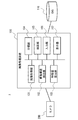
- FIG. 2 shows the configuration of the image processing apparatus 100 according to the present embodiment.
- the image processing device 100 constitutes the image processing system 1 together with the camera 200 and the database (DB) 110.
- the image processing system 1 including the image processing device 100 is a system for classifying and searching states such as posture and behavior of a person based on the skeleton structure of the person estimated from the image.
- the image processing device 100 also functions as an image selection device.
- the camera 200 is an image pickup unit such as a surveillance camera that generates a two-dimensional image.
- the camera 200 is installed at a predetermined location and captures a person or the like in the imaging region from the installation location.
- the camera 200 is directly connected so that the captured image (video) can be output to the image processing device 100, or is connected via a network or the like.
- the camera 200 may be provided inside the image processing device 100.
- the database 110 is a database that stores information (data), processing results, and the like necessary for processing of the image processing apparatus 100.
- the database 110 includes an image acquired by the image acquisition unit 101, a detection result of the skeletal structure detection unit 102, data for machine learning, a feature amount calculated by the feature amount calculation unit 103, a classification result of the classification unit 104, and a search unit 105. The search results etc. of are memorized.
- the database 110 is directly connected to the image processing device 100 so that data can be input / output as needed, or is connected via a network or the like.
- the database 110 may be provided inside the image processing device 100 as a non-volatile memory such as a flash memory, a hard disk device, or the like.
- the image processing device 100 includes an image acquisition unit 101, a skeleton structure detection unit 102, a feature amount calculation unit 103, a classification unit 104, a search unit 105, an input unit 106, and a display unit 107. ..
- the configuration of each part (block) is an example, and may be composed of other parts as long as the method (operation) described later is possible.
- the image processing device 100 is realized by, for example, a computer device such as a personal computer or a server that executes a program, but it may be realized by one device or by a plurality of devices on a network. good.
- the input unit 106, the display unit 107, and the like may be used as an external device.
- both the classification unit 104 and the search unit 105 may be provided, or only one of them may be provided.
- Both or one of the classification unit 104 and the search unit 105 is a recognition unit that performs recognition processing of the state of a person.
- the image acquisition unit 101 acquires a two-dimensional image including a person captured by the camera 200.
- the image acquisition unit 101 acquires, for example, an image including a person (a video including a plurality of images) captured by the camera 200 during a predetermined monitoring period.
- an image including a person prepared in advance may be acquired from the database 110 or the like.
- the skeleton structure detection unit 102 detects the two-dimensional skeleton structure of a person in the image based on the acquired two-dimensional image.
- the skeleton structure detection unit 102 detects the skeleton structure of all the persons recognized in the acquired image.
- the skeleton structure detection unit 102 detects the skeleton structure of a person based on the characteristics such as the joints of the person to be recognized by using the skeleton estimation technique using machine learning.
- the skeleton structure detection unit 102 uses, for example, a skeleton estimation technique such as OpenPose of Non-Patent Document 1.
- the feature amount calculation unit 103 calculates the feature amount of the detected two-dimensional skeletal structure, associates the calculated feature amount with the image to be processed, and stores it in the database 110.
- the feature amount of the skeletal structure indicates the characteristics of the skeleton of the person, and is an element for classifying or searching the state of the person based on the skeleton of the person. Usually, this feature quantity includes a plurality of parameters (for example, classification elements described later).
- the feature amount may be an entire feature amount of the skeletal structure, a partial feature amount of the skeletal structure, or a plurality of feature amounts such as each part of the skeletal structure.
- the feature amount may be calculated by any method such as machine learning or normalization, and the minimum value or the maximum value may be obtained as the normalization.
- the feature amount is a feature amount obtained by machine learning the skeletal structure, a size on an image of the skeletal structure from the head to the foot, and the like.
- the size of the skeleton structure is the vertical height and area of the skeleton region including the skeleton structure on the image.
- the vertical direction (height direction or vertical direction) is a vertical direction (Y-axis direction) in the image, and is, for example, a direction perpendicular to the ground (reference plane).
- the left-right direction (horizontal direction) is a left-right direction (X-axis direction) in the image, and is, for example, a direction parallel to the ground.
- a feature amount having robustness for the classification and search processing it is preferable to use a feature amount having robustness for the classification and search processing.
- a robust feature amount may be used for the orientation or body shape of the person. It depends on the orientation and body shape of the person by learning the skeleton of a person who is facing in various directions with the same posture and the skeleton of a person with various body shapes in the same posture, and by extracting the characteristics of the skeleton only in the vertical direction. It is possible to obtain a feature amount that does not.
- the classification unit 104 classifies (clusters) a plurality of skeletal structures stored in the database 110 based on the similarity of the feature amounts of the skeletal structures. It can be said that the classification unit 104 classifies the states of a plurality of persons based on the feature amount of the skeletal structure as the process of recognizing the state of the person. Similarity is the distance between features of the skeletal structure.
- the classification unit 104 may be classified according to the similarity of the features of the whole skeleton structure, or may be classified according to the similarity of the features of a part of the skeleton structure, and the first part of the skeleton structure (for example, for example). It may be classified according to the similarity of the features of both hands) and the second part (for example, both feet).
- the posture of the person may be classified based on the feature amount of the skeletal structure of the person in each image, or the behavior of the person based on the change in the feature amount of the skeletal structure of the person in a plurality of consecutive images in time series. May be classified. That is, the classification unit 104 can classify the state of the person including the posture and behavior of the person based on the feature amount of the skeletal structure. For example, the classification unit 104 targets a plurality of skeletal structures in a plurality of images captured during a predetermined monitoring period. The classification unit 104 obtains the degree of similarity between the features to be classified, and classifies the skeletal structures having a high degree of similarity into the same cluster (group with similar postures). As with the search, the user may be able to specify the classification conditions. The classification unit 104 stores the classification result of the skeletal structure in the database 110 and displays it on the display unit 107.
- the search unit 105 searches for a skeleton structure having a high degree of similarity to the feature amount of the search query (query state) from a plurality of skeleton structures stored in the database 110. It can be said that the search unit 105 searches for the state of a person who corresponds to the search condition (query state) from among the states of a plurality of people based on the feature amount of the skeleton structure as the process of recognizing the state of the person. Similar to classification, similarity is the distance between features of the skeletal structure.
- the search unit 105 may search by the similarity of the features of the whole skeleton structure, or may search by the similarity of the features of a part of the skeleton structure, and may search by the similarity of the first part of the skeleton structure (for example,). You may search by the similarity of the features of both hands) and the second part (for example, both feet).
- the posture of the person may be searched based on the feature amount of the skeletal structure of the person in each image, or the behavior of the person may be searched based on the change of the feature amount of the skeletal structure of the person in a plurality of consecutive images in time series. You may search for.
- the search unit 105 can search the state of the person including the posture and behavior of the person based on the feature amount of the skeletal structure. For example, the search unit 105 searches for features of a plurality of skeletal structures in a plurality of images captured during a predetermined monitoring period, similarly to the classification target. Further, the skeleton structure (posture) specified by the user from the classification results displayed by the classification unit 104 is used as a search query (search key). Not limited to the classification result, the search query may be selected from a plurality of unclassified skeleton structures, or the user may input the skeleton structure to be the search query.
- the search unit 105 searches for a feature amount having a high degree of similarity to the feature amount of the skeleton structure of the search query from the feature amount of the search target.
- the search unit 105 stores the search result of the feature amount in the database 110 and displays it on the display unit 107.
- the input unit 106 is an input interface for acquiring information input from a user who operates the image processing device 100.
- a user is a monitor who monitors a person in a suspicious state from an image of a surveillance camera.
- the input unit 106 is, for example, a GUI (Graphical User Interface), and information according to a user's operation is input from an input device such as a keyboard, a mouse, or a touch panel.
- the input unit 106 accepts the skeleton structure of a designated person from the skeleton structures (postures) classified by the classification unit 104 as a search query.
- the display unit 107 is a display unit that displays the result of the operation (processing) of the image processing device 100, and is, for example, a display device such as a liquid crystal display or an organic EL (ElectroLuminescence) display.
- the display unit 107 displays the classification result of the classification unit 104 and the search result of the search unit 105 on the GUI according to the degree of similarity and the like.
- FIG. 39 is a diagram showing a hardware configuration example of the image processing device 100.
- the image processing device 100 includes a bus 1010, a processor 1020, a memory 1030, a storage device 1040, an input / output interface 1050, and a network interface 1060.
- the bus 1010 is a data transmission path for the processor 1020, the memory 1030, the storage device 1040, the input / output interface 1050, and the network interface 1060 to transmit and receive data to each other.
- the method of connecting the processors 1020 and the like to each other is not limited to the bus connection.
- the processor 1020 is a processor realized by a CPU (Central Processing Unit), a GPU (Graphics Processing Unit), or the like.
- the memory 1030 is a main storage device realized by a RAM (RandomAccessMemory) or the like.
- the storage device 1040 is an auxiliary storage device realized by an HDD (Hard Disk Drive), SSD (Solid State Drive), memory card, ROM (Read Only Memory), or the like.
- the storage device 1040 stores a program module that realizes each function of the image processing device 100 (for example, an image acquisition unit 101, a skeleton structure detection unit 102, a feature amount calculation unit 103, a classification unit 104, a search unit 105, and an input unit 106). doing.
- the processor 1020 reads each of these program modules into the memory 1030 and executes them, each function corresponding to the program module is realized.
- the storage device 1040 may also function as a database 110.
- the input / output interface 1050 is an interface for connecting the image processing device 100 and various input / output devices.
- the image processing device 100 may connect to the database 110 via the input / output interface 1050.
- the network interface 1060 is an interface for connecting the image processing device 100 to the network.
- This network is, for example, LAN (Local Area Network) or WAN (Wide Area Network).
- the method of connecting the network interface 1060 to the network may be a wireless connection or a wired connection.
- the image processing device 100 may communicate with the camera 200 via the network interface 1060.
- the image processing device 100 may connect to the database 110 via the network interface 1060.
- FIG. 3 to 5 show the operation of the image processing apparatus 100 according to the present embodiment.
- FIG. 3 shows a flow from image acquisition to search processing in the image processing apparatus 100
- FIG. 4 shows a flow of classification processing (S104) in FIG. 3
- FIG. 5 shows a flow of search processing (S105) in FIG. It shows the flow.
- the image processing device 100 acquires an image from the camera 200 (S101).
- the image acquisition unit 101 acquires an image of a person in order to classify or search from the skeleton structure, and stores the acquired image in the database 110.
- the image acquisition unit 101 acquires, for example, a plurality of images captured during a predetermined monitoring period, and performs subsequent processing on all the persons included in the plurality of images.
- FIG. 6 shows an example of detecting a skeletal structure.
- an image acquired from a surveillance camera or the like contains a plurality of persons, and the skeleton structure is detected for each person included in the image.
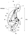
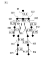
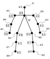
- FIG. 7 shows the skeleton structure of the human body model 300 detected at this time
- FIGS. 8 to 10 show an example of detecting the skeleton structure.
- the skeleton structure detection unit 102 detects the skeleton structure of the human body model (two-dimensional skeleton model) 300 as shown in FIG. 7 from the two-dimensional image by using a skeleton estimation technique such as OpenPose.
- the human body model 300 is a two-dimensional model composed of key points such as joints of a person and bones connecting the key points.
- the skeleton structure detection unit 102 extracts feature points that can be key points from an image, and detects each key point of a person by referring to information obtained by machine learning the image of the key points.
- the key points of the person are head A1, neck A2, right shoulder A31, left shoulder A32, right elbow A41, left elbow A42, right hand A51, left hand A52, right hip A61, left hip A62, and right knee A71.
- Left knee A72, right foot A81, left foot A82 are detected.
- Bone B31 and B32 connecting the elbow A41 and the left elbow A42, respectively, connecting the right elbow A41 and the left elbow A42 to the right hand A51 and the left hand A52, respectively, and connecting the neck A2 to the right waist A61 and the left waist A62, respectively.
- B72 is detected.
- the skeleton structure detection unit 102 stores the detected skeleton structure of the person in the database 110.
- FIG. 8 is an example of detecting an upright person.
- an upright person is imaged from the front, and bones B1, bone B51 and bone B52, bones B61 and bone B62, bones B71 and bone B72 viewed from the front are detected without overlapping, respectively, and the right foot.
- Bone B61 and Bone B71 are slightly bent more than Bone B62 and Bone B72 of the left foot.
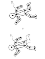
- FIG. 9 is an example of detecting a person in a crouched state.
- a crouching person is imaged from the right side, bone B1, bone B51 and bone B52, bone B61 and bone B62, bone B71 and bone B72, respectively, viewed from the right side, and bone B61 on the right foot.
- the bone B71 and the bone B62 and the bone B72 of the left foot are greatly bent and overlapped.
- FIG. 10 is an example of detecting a person who is sleeping.
- a sleeping person is imaged from diagonally left front, and bone B1, bone B51 and bone B52, bone B61 and bone B62, bone B71 and bone B72 viewed from diagonally left front are detected, respectively, and the right foot.
- the bones B61 and B71 of the left foot and the bones B62 and B72 of the left foot are bent and overlapped.
- the image processing apparatus 100 calculates the detected feature amount of the skeletal structure (S103). For example, when the height or area of the skeleton region is used as the feature amount, the feature amount calculation unit 103 extracts a region including the skeleton structure and obtains the height (number of pixels) or area (pixel area) of the region. The height and area of the skeletal region can be obtained from the coordinates of the end of the extracted skeleton region and the coordinates of the key points at the ends. The feature amount calculation unit 103 stores the obtained feature amount of the skeletal structure in the database 110.
- the feature amount of this skeletal structure is also used as posture information indicating the posture of a person. Further, the feature amount of this skeletal structure is the reliability of the feature amount and the reliability of the feature amount stored in the database 110 is the certainty that the feature amount is the feature amount (that is, the probability that the estimation result of the posture is correct). Shows. When the reliability of a certain feature is high, the probability of that feature is high.
- the reliability of the feature amount is calculated by using, for example, the number of key points used when setting the feature amount of the skeleton structure and the reliability of the key points. For example, as the number of joints increases, the reliability of the feature quantity increases. Further, the higher the reliability of the key point, the higher the reliability of the feature quantity.
- the skeletal region including all bones is extracted from the skeletal structure of an upright person.
- the upper end of the skeletal region is the key point A1 of the head
- the lower end of the skeletal region is the key point A82 of the left foot
- the left end of the skeletal region is the key point A41 of the right elbow
- the right end of the skeletal region is the key point A52 of the left hand. .. Therefore, the height of the skeleton region is obtained from the difference between the Y coordinates of the key point A1 and the key point A82.
- the width of the skeleton region is obtained from the difference between the X coordinates of the key point A41 and the key point A52, and the area is obtained from the height and width of the skeleton region.
- the skeletal region including all bones is extracted from the skeletal structure of a crouched person.
- the upper end of the skeletal region is the key point A1 of the head
- the lower end of the skeletal region is the key point A81 of the right foot
- the left end of the skeletal region is the key point A61 of the right hip
- the right end of the skeletal region is the key point A51 of the right hand. .. Therefore, the height of the skeleton region is obtained from the difference between the Y coordinates of the key point A1 and the key point A81.
- the width of the skeleton region is obtained from the difference between the X coordinates of the key point A61 and the key point A51, and the area is obtained from the height and width of the skeleton region.
- a skeletal region including all bones is extracted from the skeletal structure of a person who has fallen in the left-right direction of the image.
- the upper end of the skeleton region is the key point A32 of the left shoulder
- the lower end of the skeleton region is the key point A52 of the left hand
- the left end of the skeleton region is the key point A51 of the right hand
- the right end of the skeleton region is the key point A82 of the left foot. Therefore, the height of the skeleton region is obtained from the difference between the Y coordinates of the key point A32 and the key point A52.
- the width of the skeleton region is obtained from the difference between the X coordinates of the key point A51 and the key point A82, and the area is obtained from the height and width of the skeleton region.
- the image processing apparatus 100 performs classification processing (S104).
- the classification unit 104 calculates the similarity of the calculated feature amount of the skeletal structure (S111), and classifies the skeletal structure based on the calculated feature amount (S112). ..
- the classification unit 104 obtains the similarity of the features between all the skeletal structures stored in the database 110 to be classified, and classifies (clusters) the skeletal structures (postures) having the highest similarity into the same cluster. .. Further, the similarity between the classified clusters is obtained and classified, and the classification is repeated until a predetermined number of clusters are obtained.
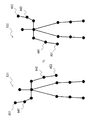
- FIG. 11 shows an image of the classification result of the feature amount of the skeletal structure.
- the feature quantities of the plurality of skeletal structures are classified into three clusters C1 to C3.
- the clusters C1 to C3 correspond to each posture such as a standing posture, a sitting posture, and a sleeping posture, and the skeletal structure (person) is classified for each similar posture.
- various classification methods can be used by classifying based on the feature amount of the skeletal structure of a person.
- the classification method may be set in advance or may be arbitrarily set by the user. Further, the classification may be performed by the same method as the search method described later. That is, it may be classified according to the same classification conditions as the search conditions.
- the classification unit 104 classifies by the following classification method. Any classification method may be used, or an arbitrarily selected classification method may be combined.
- Classification method 1 Classification by multiple layers Classification by skeletal structure of the whole body, classification by skeletal structure of upper body and lower body, classification by skeletal structure of arms and legs, etc. are classified in a hierarchical combination. That is, the classification may be performed based on the feature amounts of the first portion and the second portion of the skeletal structure, and further, the feature amounts of the first portion and the second portion may be weighted and classified.
- Classification method 2 Classification by multiple images along the time series Classification is based on the feature amount of the skeletal structure in a plurality of images continuous in the time series.
- the feature quantities may be stacked in the time series direction and classified based on the cumulative value. Further, it may be classified based on the change (change amount) of the feature amount of the skeletal structure in a plurality of continuous images.
- Classification method 3 Classification ignoring the left and right sides of the skeletal structure Classify the skeletal structures whose right and left sides are opposite to each other as the same skeletal structure.
- the classification unit 104 displays the classification result of the skeletal structure (S113).
- the classification unit 104 acquires images of necessary skeleton structures and people from the database 110, and displays the skeleton structure and people on the display unit 107 for each posture (cluster) similar as a classification result.
- FIG. 12 shows a display example when the postures are classified into three. For example, as shown in FIG. 12, the posture regions WA1 to WA3 for each posture are displayed in the display window W1, and the skeletal structure and the person (image) of the posture corresponding to each of the posture regions WA1 to WA3 are displayed.
- the posture region WA1 is, for example, a display region of a standing posture, and displays a skeletal structure and a person similar to a standing posture classified into cluster C1.
- the posture area WA2 is, for example, a sitting posture display area, and displays a skeletal structure and a person similar to the sitting posture classified into cluster C2.
- the posture area WA3 is, for example, a display area of a sleeping posture, and displays a skeletal structure and a person similar to the sleeping posture classified into cluster C2.
- the image processing apparatus 100 performs a search process (S105).
- the search unit 105 accepts the input of the search condition (S121) and searches for the skeleton structure based on the search condition (S122).
- the search unit 105 receives input of a search query, which is a search condition, from the input unit 106 according to the user's operation.
- the user specifies (selects) the skeleton structure of the posture to be searched from the posture areas WA1 to WA3 displayed in the display window W1. ..
- the search unit 105 uses the skeleton structure specified by the user as a search query to search for a skeleton structure having a high degree of similarity in the feature amount from all the skeleton structures stored in the database 110 to be searched.
- the search unit 105 calculates the similarity between the feature amount of the skeletal structure of the search query and the feature amount of the skeletal structure to be searched, and extracts the skeletal structure whose calculated similarity is higher than a predetermined threshold value.
- the feature amount of the skeleton structure of the search query the feature amount calculated in advance may be used, or the feature amount obtained at the time of search may be used.
- the search query may be input by moving each part of the skeleton structure according to the operation of the user, or the posture demonstrated by the user in front of the camera may be used as the search query.
- search method can be used by searching based on the feature amount of the skeletal structure of the person.
- the search method may be preset or may be arbitrarily set by the user.
- the search unit 105 searches by the following search method. Either search method may be used, or an arbitrarily selected search method may be combined.
- a plurality of search methods search conditions may be combined and searched by a logical expression (for example, AND (logical product), OR (logical sum), NOT (negation)).
- search condition may be searched as "(posture in which the right hand is raised) AND (posture in which the left foot is raised)".
- (Search method 1) Search by only the feature amount in the height direction By searching using only the feature amount in the height direction of the person, the influence of the lateral change of the person can be suppressed, and the direction of the person and the person can be suppressed. Improves robustness against changes in body shape. For example, as in the skeletal structures 501 to 503 of FIG. 13, even if the orientation and body shape of the person are different, the feature amount in the height direction does not change significantly. Therefore, in the skeletal structures 501 to 503, it can be determined that the postures are the same at the time of searching (at the time of classification).
- search method 2 If a part of the person's body is hidden in the partial search image, search using only the information of the recognizable part. For example, as in the skeletal structures 511 and 512 of FIG. 14, even if the key point of the left foot cannot be detected due to the hiding of the left foot, the feature amount of other detected key points can be used for the search. Therefore, in the skeletal structures 511 and 512, it can be determined that the postures are the same at the time of searching (at the time of classification). That is, it is possible to perform classification and search using the features of some key points instead of all the key points. In the examples of the skeletal structures 521 and 522 of FIG.
- the feature quantities of the key points of the upper body (A1, A2, A31, A32, A41, A42, A51, A52) are used as the search query. Therefore, it can be determined that the posture is the same. Further, the portion (feature point) to be searched may be weighted and searched, or the threshold value for determining the similarity may be changed. When a part of the body is hidden, the hidden part may be ignored and the search may be performed, or the hidden part may be added to the search. By searching including hidden parts, it is possible to search for postures in which the same part is hidden.
- (Search method 3) Search ignoring the left and right sides of the skeleton structure Search for the same skeleton structure on the right and left sides of the person.
- the posture in which the right hand is raised and the posture in which the left hand is raised can be searched (classified) as the same posture.
- the skeletal structure 531 and the skeletal structure 532 have different positions of the right hand key point A51, the right elbow key point A41, the left hand key point A52, and the left elbow key point A42, but other key points. The position of is the same.
- Search method 4 Search by features in the vertical and horizontal directions After searching only with the features in the vertical direction (Y-axis direction) of the person, the obtained results are further added to the horizontal direction (X-axis direction) of the person. Search using the features of.
- search method 5 Search by multiple images along the time series Search based on the feature quantity of the skeletal structure in a plurality of images continuous in the time series.
- the feature quantities may be stacked in the time series direction and searched based on the cumulative value.
- the search may be performed based on the change (change amount) of the feature amount of the skeletal structure in a plurality of consecutive images.
- the search unit 105 displays the search result of the skeletal structure (S123).
- the search unit 105 acquires images of necessary skeleton structures and people from the database 110, and displays the skeleton structures and people obtained as search results on the display unit 107. For example, when multiple search queries (search conditions) are specified, the search results are displayed for each search query.
- FIG. 17 shows a display example when a search is performed using three search queries (postures). For example, as shown in FIG. 17, in the display window W2, the skeleton structure and the person of the search queries Q10, Q20, and Q30 specified at the left end are displayed, and each search query is displayed on the right side of the search queries Q10, Q20, and Q30.
- the skeletal structures and people of the search results Q11, Q21, and Q31 are displayed side by side.
- the order in which the search results are displayed side by side from the side of the search query may be the order in which the corresponding skeletal structure is found or the order in which the degree of similarity is high.
- the weighted and calculated similarity may be displayed in order. It may be displayed in the order of similarity calculated from only the part (feature point) selected by the user. Further, the images (frames) before and after the time series may be cut out and displayed for a certain period of time, centering on the image (frame) of the search result.
- Search method 6 In this search method, a plurality of searched images are set using the reliability of the posture information of the images.
- FIG. 40 is a diagram showing an example of the functional configuration of the search unit 105 according to this search method.
- the search unit 105 includes a query acquisition unit 610, a search information acquisition unit 620, a selection unit 630, and a display control unit 640.
- the query acquisition unit 610 acquires posture information (hereinafter referred to as query posture information) indicating the posture of a person, which is information to be a query.
- posture information hereinafter referred to as query posture information
- the search information acquisition unit 620 acquires a plurality of search posture information.
- the search posture information is posture information of an image to be searched (hereinafter referred to as a target image), and is stored in the database 110 for each of a plurality of target images.
- the selection unit 630 selects two or more search posture information whose similarity to the query posture information satisfies the criteria among the plurality of search posture information.
- This selection process is substantially a process of selecting a target image similar to an image corresponding to the posture information for query (hereinafter referred to as a query image).
- the display control unit 640 displays the target image corresponding to each of the two or more search posture information selected by the selection unit 630 on the display unit 107, and displays the display position of these target images on the reliability of the search posture information. Set using. This reliability is stored in the database 110 as described above.
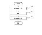
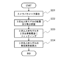
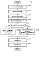
- FIG. 41 is a flowchart showing an example of the processing performed by the search unit 105 according to the present search method.
- the query acquisition unit 610 acquires query posture information (step S300).
- the query acquisition unit 610 acquires query posture information from the database 110.
- the user inputs an input for specifying the query image to the query acquisition unit 610.
- the query acquisition unit 610 reads the query posture information corresponding to the query image from the database 110.
- the query acquisition unit 610 may acquire an image to be a query from an external device.
- the skeletal structure detection unit 102 and the feature amount calculation unit 103 process this image to calculate the feature amount of the skeletal structure. Then, the query acquisition unit 610 acquires the feature amount of this skeletal structure as the posture information for query.
- the search information acquisition unit 620 acquires a plurality of posture information stored in the database 110 as search information (step S310).
- the selection unit 630 selects two or more search posture information having a similarity to the query posture information as a criterion from the plurality of search posture information (step S320).
- the processing performed here is performed using, for example, at least one of the above-mentioned search methods 1 to 5, but may be performed using another method.
- the display control unit 640 reads out the target image corresponding to the search posture information selected in step S320 from the database 110. Since two or more search posture information are selected in step S320, the display control unit 640 also reads two or more target images from the database 110. At this time, the display control unit 640 also reads the reliability of each target image from the database 110 (step S330).
- the display control unit 640 sets the display position of each target image using the reliability of the target image (step S340).
- the reliability indicates the probability that the posture estimation result is correct. Therefore, if the reliability is high, the possibility that the target image is similar to the query image is high. Therefore, if the display position of the target image is set using the reliability of the target image, the user can be made to recognize the influence of the reliability of each target image on the validity of the selection result in step S320.
- the display control unit 640 causes the display unit 107 to display the target image read in step S330. At this time, the display control unit 640 displays each target image at the display position determined in step S340 (step S350).
- the selection unit 630 stores the selection result of step S320 in the database 110 (step S360).
- the selection unit 630 may store the target image read in step S330 in the database 110 as one cluster, or the target image already stored in the database 110 may be stored in the database 110 as a query image. It may be associated with a flag indicating that they are similar.
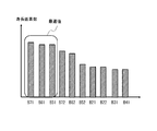
- FIG. 42 is a diagram showing an example of a method for determining a display position of a target image, which is performed in step S340.
- the display control unit 640 displays the target images on the display unit 107 in descending order of reliability.
- the order of the target images is not limited to this example.
- the display control unit 640 causes the display unit 107 to display the target image together with the reliability of the search posture information of the target image. By doing so, the user can directly confirm the reliability of the selected target image, and thus can grasp the reliability required to obtain a reasonable selection result.
- FIG. 43 is a flowchart showing a modification 1 of FIG. 41.
- the display control unit 640 determines the display position of the target image, in addition to the reliability of the target image, the similarity between the target image and the query image, that is, the posture information for search and the query It is the same as in FIG. 41 except that the similarity of the posture information is also used (step S342).
- the display control unit 640 determines the order of the target images using the above-mentioned reliability and similarity. For example, the display control unit 640 calculates the evaluation value using the above-mentioned function with the reliability and the similarity as parameters, and displays the target images in descending order of the evaluation value (or in ascending order).
- An example of this function is to calculate the sum of reliability and similarity after adding predetermined weighting coefficients to each of them.
- FIG. 44 is a flowchart showing a modification 2 of FIG. 41.
- the display control unit 640 determines the display position of the target image on condition that a predetermined condition is satisfied (step S332: Yes), in addition to the reliability of the target image.
- the similarity between the target image and the query image is also used instead of this reliability (step S344).
- step S342 The process when the similarity between the target image and the query image is used in addition to the reliability of the target image is the same as step S342 in FIG. 43. Further, the process when the similarity between the target image and the query image is used instead of the reliability of the target image is the same as step S340 in FIG. 41 except that the similarity is used.
- the present embodiment it is possible to detect the skeletal structure of a person from a two-dimensional image and perform classification and search based on the feature amount of the detected skeletal structure. As a result, it is possible to classify by similar postures having a high degree of similarity, and it is possible to search for similar postures having a high degree of similarity with a search query (search key).
- search key search key
- the posture of the person in the image can be grasped without the user specifying the posture or the like. Since the user can specify the posture of the search query from the classification results, the desired posture can be searched even if the user does not know the posture to be searched in detail in advance. For example, since it is possible to perform classification and search on the condition of the whole or part of the skeleton structure of a person, flexible classification and search is possible.
- the display position of the target image is set using the reliability of the target image. Therefore, the user can be made aware of the influence of the reliability of each target image on the validity of the selection result.
- FIG. 18 shows the configuration of the image processing apparatus 100 according to the present embodiment.
- the image processing apparatus 100 further includes a height calculation unit 108 in addition to the configuration of the first embodiment.
- the feature amount calculation unit 103 and the height calculation unit 108 may be combined into one processing unit.
- the height calculation unit (height estimation unit) 108 calculates the height of the person in the two-dimensional image when standing upright (referred to as the number of height pixels) based on the two-dimensional skeleton structure detected by the skeleton structure detection unit 102 (referred to as the number of height pixels). presume. It can also be said that the number of height pixels is the height of the person in the two-dimensional image (the length of the whole body of the person in the two-dimensional image space). The height calculation unit 108 obtains the number of height pixels (number of pixels) from the length (length on the two-dimensional image space) of each bone of the detected skeleton structure.
- specific examples 1 to 3 are used as a method for obtaining the number of height pixels.
- any of the methods of Specific Examples 1 to 3 may be used, or a plurality of arbitrarily selected methods may be used in combination.
- the number of height pixels is obtained by summing the lengths of the bones from the head to the foot among the bones of the skeletal structure. If the skeleton structure detection unit 102 (skeleton estimation technique) does not output the top of the head and the feet, it can be corrected by multiplying by a constant as necessary.
- the number of height pixels is calculated using a human body model showing the relationship between the length of each bone and the length of the whole body (height on a two-dimensional image space).
- the number of height pixels is calculated by fitting (fitting) a three-dimensional human body model to a two-dimensional skeleton structure.
- the feature amount calculation unit 103 of the present embodiment is a normalization unit that normalizes the skeletal structure (skeleton information) of a person based on the calculated number of height pixels of the person.
- the feature amount calculation unit 103 stores the feature amount (normalized value) of the normalized skeletal structure in the database 110.
- the feature amount calculation unit 103 normalizes the height of each key point (feature point) included in the skeleton structure on the image by the number of height pixels.
- the height direction is the vertical direction (Y-axis direction) in the two-dimensional coordinate (XY coordinate) space of the image. In this case, the height of the key point can be obtained from the value (number of pixels) of the Y coordinate of the key point.
- the height direction may be the direction of the vertical axis perpendicular to the ground (reference plane) in the three-dimensional coordinate space in the real world, and the direction of the vertical projection axis projected onto the two-dimensional coordinate space (vertical projection direction).
- the height of the key point is the vertical projection axis obtained by projecting the axis perpendicular to the ground in the real world onto the two-dimensional coordinate space based on the camera parameters, and the value along this vertical projection axis (number of pixels). ) Can be obtained.
- the camera parameters are image imaging parameters, and for example, the camera parameters are the posture, position, imaging angle, focal length, and the like of the camera 200.
- the camera 200 can take an image of an object whose length and position are known in advance, and obtain camera parameters from the image. Distortion occurs at both ends of the captured image, and the vertical direction of the real world may not match the vertical direction of the image. On the other hand, by using the parameters of the camera that took the image, you can see how much the vertical direction in the real world is tilted in the image. Therefore, by normalizing the value of the key point along the vertical projection axis projected in the image based on the camera parameters by height, it is possible to quantify the key point in consideration of the deviation between the real world and the image. can.
- the left-right direction is the left-right direction (X-axis direction) in the two-dimensional coordinate (XY coordinates) space of the image, or the direction parallel to the ground in the three-dimensional coordinate space in the real world. Is the direction projected onto the two-dimensional coordinate space.
- 19 to 23 show the operation of the image processing device 100 according to the present embodiment.
- 19 shows a flow from image acquisition to search processing in the image processing apparatus 100
- FIGS. 20 to 22 show the flow of specific examples 1 to 3 of the height pixel number calculation process (S201) of FIG. 23 shows the flow of the normalization process (S202) of FIG.
- the height pixel number calculation process (S201) and the normalization process (S202) are performed as the feature amount calculation process (S103) in the first embodiment. Others are the same as those in the first embodiment.
- the image processing device 100 performs height pixel number calculation processing based on the detected skeleton structure (S201) following the image acquisition (S101) and the skeleton structure detection (S102).
- the height of the skeleton structure of the person standing upright in the image is the height pixel number (h)
- the height of each key point of the skeleton structure in the state of the person in the image is the key point. Let it be the height (yi).
- specific examples 1 to 3 of the height pixel number calculation process will be described.
- Specific Example 1 the number of height pixels is obtained using the length of the bone from the head to the foot.
- the height calculation unit 108 acquires the length of each bone (S211) and totals the lengths of the acquired bones (S212).
- the height calculation unit 108 acquires the length of the bone on the two-dimensional image of the foot from the head of the person, and obtains the number of height pixels. That is, from the image in which the skeletal structure is detected, among the bones of FIG. 24, bone B1 (length L1), bone B51 (length L21), bone B61 (length L31) and bone B71 (length L41), or , Bone B1 (length L1), bone B52 (length L22), bone B62 (length L32), and bone B72 (length L42) are acquired. The length of each bone can be obtained from the coordinates of each key point in the two-dimensional image.
- the longer value is taken as the number of height pixels. That is, each bone has the longest length in the image when it is imaged from the front, and it is displayed short when it is tilted in the depth direction with respect to the camera. Therefore, it is more likely that the longer bone is imaged from the front, which is considered to be closer to the true value. Therefore, it is preferable to select the longer value.
- bone B1, bone B51 and bone B52, bone B61 and bone B62, bone B71 and bone B72 are detected without overlapping.
- the total of these bones, L1 + L21 + L31 + L41 and L1 + L22 + L32 + L42, is obtained, and for example, the value obtained by multiplying L1 + L22 + L32 + L42 on the left foot side where the detected bone length is long by a correction constant is taken as the height pixel number.
- bone B1, bone B51 and bone B52, bone B61 and bone B62, bone B71 and bone B72 are detected, respectively, and the right foot bone B61 and bone B71 and the left foot bone B62 and bone B72 overlap each other. ..
- the total of these bones, L1 + L21 + L31 + L41 and L1 + L22 + L32 + L42, is obtained, and for example, the value obtained by multiplying L1 + L21 + L31 + L41 on the right foot side where the detected bone length is long by a correction constant is taken as the height pixel number.
- bone B1, bone B51 and bone B52, bone B61 and bone B62, bone B71 and bone B72 are detected, respectively, and the right foot bone B61 and bone B71 and the left foot bone B62 and bone B72 overlap each other. ..
- the total of these bones, L1 + L21 + L31 + L41 and L1 + L22 + L32 + L42, is obtained, and for example, the value obtained by multiplying L1 + L22 + L32 + L42 on the left foot side where the detected bone length is long by a correction constant is taken as the height pixel number.
- the height can be calculated by summing the lengths of the bones from the head to the feet, so the number of height pixels can be calculated by a simple method.
- the number of height pixels can be accurately calculated even when the entire person is not always shown in the image, such as when crouching down. Can be estimated.
- Specific Example 2 the number of height pixels is obtained using a two-dimensional skeleton model showing the relationship between the length of the bone included in the two-dimensional skeleton structure and the length of the whole body of the person in the two-dimensional image space.
- FIG. 28 is a human body model (two-dimensional skeleton model) 301 showing the relationship between the length of each bone in the two-dimensional image space and the length of the whole body in the two-dimensional image space used in the second embodiment.
- the relationship between the length of each bone of an average person and the length of the whole body is associated with each bone of the human body model 301.
- the length of the bone B1 of the head is the length of the whole body ⁇ 0.2 (20%)
- the length of the bone B41 of the right hand is the length of the whole body ⁇ 0.15 (15%)
- the length of the right foot is the length of the whole body ⁇ 0.25 (25%).
- the average whole body length can be obtained from the length of each bone.
- a human body model may be prepared for each attribute of the person such as age, gender, and nationality. As a result, the length (height) of the whole body can be appropriately obtained according to the attributes of the person.
- the height calculation unit 108 acquires the length of each bone (S221).
- the height calculation unit 108 acquires the lengths (lengths in the two-dimensional image space) of all the bones in the detected skeleton structure.
- FIG. 29 is an example in which a person in a crouched state is imaged from diagonally right behind and the skeletal structure is detected. In this example, since the face and left side of the person are not shown, the bones of the head, the left arm, and the bones of the left hand cannot be detected. Therefore, the lengths of the detected bones B21, B22, B31, B41, B51, B52, B61, B62, B71, and B72 are acquired.
- the height calculation unit 108 calculates the number of height pixels from the length of each bone based on the human body model (S222).
- the height calculation unit 108 refers to the human body model 301 showing the relationship between each bone and the length of the whole body as shown in FIG. 28, and obtains the number of height pixels from the length of each bone. For example, since the length of the bone B41 on the right hand is the length of the whole body ⁇ 0.15, the number of height pixels based on the bone B41 is obtained from the length of the bone B41 / 0.15. Further, since the length of the bone B71 of the right foot is the length of the whole body ⁇ 0.25, the number of height pixels based on the bone B71 is obtained from the length of the bone B71 / 0.25.
- the human body model referred to at this time is, for example, a human body model of an average person, but a human body model may be selected according to the attributes of the person such as age, gender, and nationality. For example, when a person's face is shown in the captured image, the attribute of the person is identified based on the face, and the human body model corresponding to the identified attribute is referred to. It is possible to recognize a person's attributes from the facial features of the image by referring to the information obtained by machine learning the face for each attribute. Further, when the attribute of the person cannot be identified from the image, the human body model of the average person may be used.
- the number of height pixels calculated from the length of the bone may be corrected by the camera parameter. For example, when the camera is taken at a high position and looking down at a person, the horizontal length of the shoulder-width bones, etc. is not affected by the depression angle of the camera in the two-dimensional skeletal structure, but the vertical length of the neck-waist bones, etc. The length decreases as the depression angle of the camera increases. Then, the number of height pixels calculated from the horizontal length of the shoulder-width bones and the like tends to be larger than the actual number.
- the height calculation unit 108 calculates the optimum value of the number of height pixels as shown in FIG. 21 (S223).
- the height calculation unit 108 calculates the optimum value of the number of height pixels from the number of height pixels obtained for each bone. For example, as shown in FIG. 30, a histogram of the number of height pixels obtained for each bone is generated, and a large number of height pixels is selected from the histogram. That is, the number of height pixels longer than the others is selected from the plurality of height pixels obtained based on the plurality of bones. For example, the upper 30% is set as a valid value, and in FIG. 30, the number of height pixels by bones B71, B61, and B51 is selected.
- the average number of selected height pixels may be obtained as the optimum value, or the largest number of height pixels may be used as the optimum value. Since the height is calculated from the length of the bone in the 2D image, the length of the bone is taken from the front when the bone is not made from the front, that is, when the bone is tilted in the depth direction when viewed from the camera. It will be shorter than the case. Then, a value having a large number of height pixels is more likely to be captured from the front than a value having a small number of height pixels, and is a more plausible value. Therefore, a larger value is set as the optimum value.
- the number of height pixels is calculated based on the detected bones of the skeleton structure using a human body model showing the relationship between the bones in the two-dimensional image space and the length of the whole body, so that all the skeletons from the head to the feet are obtained. Even if is not obtained, the number of height pixels can be obtained from some bones. In particular, the number of height pixels can be estimated accurately by adopting a larger value among the values obtained from a plurality of bones.
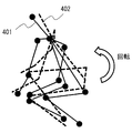
- Specific Example 3 the two-dimensional skeletal structure is fitted to the three-dimensional human body model (three-dimensional skeletal model), and the skeletal vector of the whole body is obtained using the number of height pixels of the fitted three-dimensional human body model.
- the height calculation unit 108 first calculates the camera parameters based on the image captured by the camera 200 (S231).
- the height calculation unit 108 extracts an object whose length is known in advance from a plurality of images captured by the camera 200, and obtains a camera parameter from the size (number of pixels) of the extracted object.
- the camera parameters may be obtained in advance, and the obtained camera parameters may be acquired as needed.
- the height calculation unit 108 adjusts the arrangement and height of the three-dimensional human body model (S232).
- the height calculation unit 108 prepares a three-dimensional human body model for calculating the number of height pixels for the detected two-dimensional skeleton structure, and arranges the three-dimensional human body model in the same two-dimensional image based on the camera parameters.
- the "relative positional relationship between the camera and the person in the real world" is specified from the camera parameters and the two-dimensional skeleton structure. For example, assuming that the position of the camera is the coordinates (0, 0, 0), the coordinates (x, y, z) of the position where the person is standing (or sitting) are specified. Then, by assuming an image in which a three-dimensional human body model is placed at the same position (x, y, z) as the specified person and captured, the two-dimensional skeleton structure and the three-dimensional human body model are superimposed.
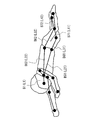
- FIG. 31 is an example in which a crouching person is imaged diagonally from the front left and the two-dimensional skeleton structure 401 is detected.
- the two-dimensional skeleton structure 401 has two-dimensional coordinate information. It is preferable that all bones are detected, but some bones may not be detected.
- a three-dimensional human body model 402 as shown in FIG. 32 is prepared.
- the three-dimensional human body model (three-dimensional skeleton model) 402 has three-dimensional coordinate information and is a model of a skeleton having the same shape as the two-dimensional skeleton structure 401.
- the prepared three-dimensional human body model 402 is arranged and superimposed on the detected two-dimensional skeleton structure 401.
- the height of the three-dimensional human body model 402 is adjusted so as to match the two-dimensional skeleton structure 401.
- the three-dimensional human body model 402 prepared at this time may be a model in a state close to the posture of the two-dimensional skeleton structure 401 as shown in FIG. 33, or may be a model in an upright state.
- a 3D human body model 402 of the estimated posture may be generated by using a technique of estimating the posture of the 3D space from the 2D image using machine learning. By learning the information of the joints in the 2D image and the joints in the 3D space, the 3D posture can be estimated from the 2D image.
- the height calculation unit 108 fits the three-dimensional human body model into the two-dimensional skeletal structure as shown in FIG. 22 (S233). As shown in FIG. 34, the height calculation unit 108 superimposes the three-dimensional human body model 402 on the two-dimensional skeletal structure 401 so that the postures of the three-dimensional human body model 402 and the two-dimensional skeletal structure 401 match.
- the dimensional human body model 402 is transformed. That is, the height, body orientation, and joint angle of the three-dimensional human body model 402 are adjusted and optimized so that there is no difference from the two-dimensional skeletal structure 401.
- the joints of the three-dimensional human body model 402 are rotated within the range of movement of the person, the entire three-dimensional human body model 402 is rotated, and the overall size is adjusted.
- the fitting of the three-dimensional human body model and the two-dimensional skeletal structure is performed in the two-dimensional space (two-dimensional coordinates). That is, the 3D human body model is mapped to the 2D space, and the 3D human body model is converted into a 2D skeletal structure in consideration of how the deformed 3D human body model changes in the 2D space (image). Optimize.
- the height calculation unit 108 calculates the number of height pixels of the fitted three-dimensional human body model as shown in FIG. 22 (S234). As shown in FIG. 35, the height calculation unit 108 obtains the number of height pixels of the three-dimensional human body model 402 in that state when the difference between the three-dimensional human body model 402 and the two-dimensional skeleton structure 401 disappears and the postures match. With the optimized 3D human body model 402 upright, the length of the whole body in 2D space is obtained based on the camera parameters. For example, the height pixel number is calculated from the bone length (number of pixels) from the head to the foot when the three-dimensional human body model 402 is upright. Similar to the first embodiment, the lengths of the bones from the head to the foot of the three-dimensional human body model 402 may be totaled.
- the image processing device 100 performs a normalization process (S202) following the height pixel number calculation process.
- the feature amount calculation unit 103 calculates the key point height (S241).
- the feature amount calculation unit 103 calculates the key point height (number of pixels) of all the key points included in the detected skeleton structure.
- the key point height is the length (number of pixels) in the height direction from the lowest end of the skeleton structure (for example, the key point of any foot) to the key point.
- the height of the key point is obtained from the Y coordinate of the key point in the image.
- the key point height may be obtained from the length in the direction along the vertical projection axis based on the camera parameters.
- the height (y) of the key point A2 of the neck is a value obtained by subtracting the Y coordinate of the key point A81 of the right foot or the Y coordinate of the key point A82 of the left foot from the Y coordinate of the key point A2.
- the reference point is a reference point for expressing the relative height of the key point.
- the reference point may be preset or may be selectable by the user.
- the reference point is preferably the center or higher than the center of the skeletal structure (upper and lower in the vertical direction of the image), and for example, the coordinates of the key point of the neck are used as the reference point.
- the coordinates of the head and other key points, not limited to the neck, may be used as the reference point.
- any coordinate for example, the center coordinate of the skeleton structure may be used as a reference point.
- the feature amount calculation unit 103 normalizes the key point height (yi) by the number of height pixels (S243).
- the feature amount calculation unit 103 normalizes each key point by using the key point height, the reference point, and the number of height pixels of each key point. Specifically, the feature amount calculation unit 103 normalizes the relative height of the key point with respect to the reference point by the number of height pixels.
- the feature amount (normalized value) is obtained by using the following equation (1) with the Y coordinate of the reference point (key point of the neck) as (yc).
- (yi) and (yc) are converted into values in the direction along the vertical projection axis.
- the coordinates (x0, y0), (x1, y1), ... (X17, y17) of the 18 points of each key point are set to the following using the above equation (1). It is converted into an 18-dimensional feature amount as in.
- FIG. 36 shows an example of the feature amount of each key point obtained by the feature amount calculation unit 103.
- the feature amount of the key point A2 is 0.0
- the feature amount of the key point A31 on the right shoulder and the key point A32 on the left shoulder at the same height as the neck are also. It is 0.0.
- the feature amount of the key point A1 of the head higher than the neck is -0.2.
- the feature amount of the right hand key point A51 and the left hand key point A52 lower than the neck is 0.4, and the feature amount of the right foot key point A81 and the left foot key point A82 is 0.9.
- the feature amount of the key point A52 of the left hand is ⁇ 0.4.
- the feature amount (normalized value) of the present embodiment shows the characteristics of the skeleton structure (key point) in the height direction (Y direction), and affects the change of the skeleton structure in the lateral direction (X direction). Do not receive.
- the skeleton structure of a person is detected from the two-dimensional image, and the number of height pixels (height when standing upright on the two-dimensional image space) obtained from the detected skeleton structure is used. Normalize each key point in the skeletal structure. By using this normalized feature amount, it is possible to improve the robustness when classification, search, or the like is performed. That is, since the feature amount of the present embodiment is not affected by the lateral change of the person as described above, it is highly robust to the change of the direction of the person and the body shape of the person.
- a query acquisition method for acquiring query posture information indicating the posture of a person, which is information that serves as a query.
- Search information acquisition means for acquiring a plurality of search posture information indicating the posture of a person included in the target image, which is information generated for each of a plurality of target images to be searched.
- a selection means for selecting two or more of the search posture information having a similarity to the query posture information based on the criteria, and a selection means for selecting the search posture information.
- the target image corresponding to each of the two or more search posture information selected by the selection means is displayed on the display means, and the display position of the target image is set by using the reliability of the search posture information.
- Display control means and An image selection device comprising. 2. 2. In the image selection device described in 1 above, The display control means is an image selection device that causes a display means to display the reliability of the search posture information together with the target image corresponding to the search posture information. 3. 3. In the image selection device according to 1 or 2 above, The display control means is an image selection device that further determines a display position of the target image using the similarity. 4. In the image selection device according to 1 or 2 above, When the display control means satisfies a predetermined condition, when determining the display position of the target image, the image selection using the similarity degree instead of the search posture information or together with the search posture information. Device. 5.
- the query acquisition means is an image selection device that acquires posture information corresponding to the query image as the query posture information when the information for specifying the query image, which is an image including a person, is acquired.
- the search posture information is set using the positions of each of the plurality of joints.
- the reliability is an image selection device calculated by using the number of joints used when setting the search posture information and the reliability of the joints. 7.
- the computer causes the display means to display the reliability of the search posture information together with the target image corresponding to the search posture information, which is an image selection method.
- the computer further uses the similarity to determine the display position of the target image, which is an image selection method.
- the display control when the computer satisfies a predetermined condition, when determining the display position of the target image, the similarity is obtained in place of the search posture information or together with the search posture information. Image selection method to be used.
- the computer when the computer acquires information for specifying a query image which is an image including a person, an image selection method for acquiring posture information corresponding to the query image as the query posture information. 12.
- the search posture information is set using the positions of each of the plurality of joints.
- the reliability is an image selection method calculated by using the number of joints used when setting the search posture information and the reliability of the joints. 13.
- a query acquisition function that acquires query posture information that indicates the posture of a person, which is information that becomes a query.
- a search information acquisition function that acquires a plurality of search posture information indicating the posture of a person included in the target image, which is information generated for each of a plurality of target images to be searched.
- a selection function for selecting two or more of the search posture information having a similarity to the query posture information based on the criteria, and a selection function for selecting the search posture information.
- the target image corresponding to each of the two or more search posture information selected by the selection means is displayed on the display means, and the display position of the target image is set by using the reliability of the search posture information.
- the display control function is a program that causes a display means to display the reliability of the search posture information together with the target image corresponding to the search posture information. 15.
- the display control function is a program that further determines a display position of the target image using the similarity.
- the display control function is a program that uses the similarity degree in place of the search posture information or together with the search posture information when determining the display position of the target image when a predetermined condition is satisfied.
- the query acquisition function is a program that acquires posture information corresponding to the query image as the query posture information when the information for specifying the query image, which is an image including a person, is acquired.
- the search posture information is set using the positions of each of the plurality of joints.
- the reliability is a program calculated by using the number of joints used when setting the search posture information and the reliability of the joints.
- Image processing system 10 Image processing device (image selection device) 11 Skeleton detection unit 12 Feature amount calculation unit 13 Recognition unit 100 Image processing device (image selection device) 101 Image acquisition unit 102 Skeleton structure detection unit 103 Feature amount calculation unit 104 Classification unit 105 Search unit 106 Input unit 107 Display unit 108 Height calculation unit 110 Database 200 Camera 300, 301 Human body model 401 Two-dimensional skeleton structure 610 Query acquisition unit 620 Search Information acquisition unit 630 Selection unit 640 Display control unit
Abstract
クエリ取得部(610)は、クエリとなる情報であって、人物の姿勢を示す姿勢情報(以下、クエリ用姿勢情報と記載)を取得する。検索用情報取得部(620)は、複数の検索用姿勢情報を取得する。検索用姿勢情報は、検索対象となる画像(以下、対象画像と記載)の姿勢情報であり、複数の対象画像別にデータベースに記憶されている。選択部(630)は、複数の検索用姿勢情報のうちクエリ用姿勢情報に対する類似度が基準を満たす2つ以上の検索用姿勢情報を選択する。この選択処理は、実質的には、クエリ用姿勢情報に対応する画像(以下、クエリ画像と記載)に類似する対象画像を選択する処理になる。
Description
本発明は、画像選択装置、画像選択方法、およびプログラムに関する。
近年、監視システム等において、監視カメラの画像から人物の姿勢や行動等の状態の検出や検索を行う技術が利用されている。関連する技術として、例えば、特許文献1及び2が知られている。特許文献1には、深さ映像に含まれる人物の頭や手足等のキージョイントに基づいて、類似する人物の姿勢を検索する技術が開示されている。特許文献2には、人物の姿勢と関連しないが、画像に付加された傾き等の姿勢情報を利用して類似画像を検索する技術が開示されている。なお、その他に、人物の骨格推定に関連する技術として、非特許文献1が知られている。
一方、クエリとなる画像に類似する画像を検索する場合、検索結果には複数の画像が含まれることが多い。特許文献3には、クエリとなる画像に対する類似の度合いが高い順に画像を表示することが記載されている。
Zhe Cao, Tomas Simon, Shih-En Wei, Yaser Sheikh, "Realtime Multi-Person 2D Pose Estimation using Part Affinity Fields", The IEEE Conference on Computer Vision and Pattern Recognition (CVPR), 2017, P. 7291-7299
本発明者は、人物を含む画像を当該人物の姿勢を基準に検索する場合、検索対象となる画像の姿勢推定結果の信頼度が検索結果の妥当性に影響を与えると考えた。本発明が解決しようとする課題の一つは、人物を含む画像を当該人物の姿勢を基準に検索する場合において、検索対象となる画像の姿勢推定結果の信頼度が検索結果の妥当性に与える影響を、ユーザに認識させやすくすることにある。
本発明によれば、クエリとなる情報であって、人物の姿勢を示すクエリ用姿勢情報を取得するクエリ取得手段と、
検索対象となる複数の対象画像毎に生成された情報であって、当該対象画像に含まれる人物の姿勢を示す検索用姿勢情報を複数取得する検索用情報取得手段と、
前記複数の検索用姿勢情報のうち前記クエリ用姿勢情報に対する類似度が基準を満たす2つ以上の前記検索用姿勢情報を選択する選択手段と、
前記選択手段によって選択された前記2つ以上の検索用姿勢情報それぞれに対応する前記対象画像を表示手段に表示させるとともに、前記対象画像の表示位置を前記検索用姿勢情報の信頼度を用いて設定する表示制御手段と、
を備える画像選択装置が提供される。
検索対象となる複数の対象画像毎に生成された情報であって、当該対象画像に含まれる人物の姿勢を示す検索用姿勢情報を複数取得する検索用情報取得手段と、
前記複数の検索用姿勢情報のうち前記クエリ用姿勢情報に対する類似度が基準を満たす2つ以上の前記検索用姿勢情報を選択する選択手段と、
前記選択手段によって選択された前記2つ以上の検索用姿勢情報それぞれに対応する前記対象画像を表示手段に表示させるとともに、前記対象画像の表示位置を前記検索用姿勢情報の信頼度を用いて設定する表示制御手段と、
を備える画像選択装置が提供される。
本発明によれば、コンピュータが、
クエリとなる情報であって、人物の姿勢を示すクエリ用姿勢情報を取得し
検索対象となる複数の対象画像毎に生成された情報であって、当該対象画像に含まれる人物の姿勢を示す検索用姿勢情報を複数取得し、
前記複数の検索用姿勢情報のうち前記クエリ用姿勢情報に対する類似度が基準を満たす2つ以上の前記検索用姿勢情報を選択し、
前記選択手段によって選択された前記2つ以上の検索用姿勢情報それぞれに対応する前記対象画像を表示手段に表示させるとともに、前記対象画像の表示位置を前記検索用姿勢情報の信頼度を用いて設定する、画像選択方法が提供される。
クエリとなる情報であって、人物の姿勢を示すクエリ用姿勢情報を取得し
検索対象となる複数の対象画像毎に生成された情報であって、当該対象画像に含まれる人物の姿勢を示す検索用姿勢情報を複数取得し、
前記複数の検索用姿勢情報のうち前記クエリ用姿勢情報に対する類似度が基準を満たす2つ以上の前記検索用姿勢情報を選択し、
前記選択手段によって選択された前記2つ以上の検索用姿勢情報それぞれに対応する前記対象画像を表示手段に表示させるとともに、前記対象画像の表示位置を前記検索用姿勢情報の信頼度を用いて設定する、画像選択方法が提供される。
本発明によれば、コンピュータに、
クエリとなる情報であって、人物の姿勢を示すクエリ用姿勢情報を取得するクエリ取得機能と、
検索対象となる複数の対象画像毎に生成された情報であって、当該対象画像に含まれる人物の姿勢を示す検索用姿勢情報を複数取得する検索用情報取得機能と、
前記複数の検索用姿勢情報のうち前記クエリ用姿勢情報に対する類似度が基準を満たす2つ以上の前記検索用姿勢情報を選択する選択機能と、
前記選択手段によって選択された前記2つ以上の検索用姿勢情報それぞれに対応する前記対象画像を表示手段に表示させるとともに、前記対象画像の表示位置を前記検索用姿勢情報の信頼度を用いて設定する表示制御機能と、
を持たせるプログラムが提供される。
本発明によれば、物を含む画像を当該人物の姿勢を基準に検索する場合において、検索対象となる画像の姿勢推定結果の信頼度が検索結果の妥当性に与える影響を、ユーザに認識させやすくなる。
上述した目的、およびその他の目的、特徴および利点は、以下に述べる好適な実施の形態、およびそれに付随する以下の図面によってさらに明らかになる。
以下、本発明の実施の形態について、図面を用いて説明する。尚、すべての図面において、同様な構成要素には同様の符号を付し、適宜説明を省略する。
(実施の形態に至る検討)
近年、ディープラーニング等の機械学習を活用した画像認識技術が様々なシステムに応用されている。例えば、監視カメラの画像により監視を行う監視システムへの適用が進められている。監視システムに機械学習を活用することで、画像から人物の姿勢や行動等の状態をある程度把握することが可能とされつつある。
近年、ディープラーニング等の機械学習を活用した画像認識技術が様々なシステムに応用されている。例えば、監視カメラの画像により監視を行う監視システムへの適用が進められている。監視システムに機械学習を活用することで、画像から人物の姿勢や行動等の状態をある程度把握することが可能とされつつある。
しかしながら、このような関連する技術では、必ずしもオンデマンドにユーザが望む人物の状態を把握できない場合がある。例えば、ユーザが検索し把握したい人物の状態を事前に特定できている場合もあれば、未知の状態のように具体的に特定できていない場合もある。そうすると、場合によっては、ユーザが検索したい人物の状態を詳細に指定することができない。また、人物の体の一部が隠れているような場合には検索等を行うことができない。関連する技術では、特定の検索条件のみからしか人物の状態を検索できないため、所望の人物の状態を柔軟に検索や分類することが困難である。
そこで、発明者らは、オンデマンドに画像からユーザ所望の人物の状態を認識するため、非特許文献1などの骨格推定技術を利用する方法を検討した。非特許文献1に開示されたOpenPose等のように、関連する骨格推定技術では、様々なパターンの正解付けされた画像データを学習することで、人物の骨格を推定する。以下の実施の形態では、このような骨格推定技術を活用することで、人物の状態を柔軟に認識することを可能とする。
なお、OpenPose等の骨格推定技術により推定される骨格構造は、関節等の特徴的な点である「キーポイント」と、キーポイント間のリンクを示す「ボーン(ボーンリンク)」とから構成される。このため、以下の実施の形態では、骨格構造について「キーポイント」と「ボーン」という用語を用いて説明するが、特に限定されない限り、「キーポイント」は人物の「関節」に対応し、「ボーン」は人物の「骨」に対応している。そして「キーポイント」の位置は関節情報の一例になる。
(実施の形態の概要)
図1は、実施の形態に係る画像処理装置10の概要を示している。図1に示すように、画像処理装置10は、骨格検出部11、特徴量算出部12、及び認識部13を備えている。骨格検出部11は、カメラ等から取得される2次元画像に基づいて、複数の人物の2次元骨格構造を検出する。特徴量算出部12は、骨格検出部11により検出された複数の2次元骨格構造の特徴量を算出する。認識部13は、特徴量算出部12により算出された複数の特徴量の類似度に基づいて、複数の人物の状態の認識処理を行う。認識処理は、人物の状態の分類処理や検索処理(選択処理)等である。このため、画像処理装置10は画像選択装置としても機能する。
図1は、実施の形態に係る画像処理装置10の概要を示している。図1に示すように、画像処理装置10は、骨格検出部11、特徴量算出部12、及び認識部13を備えている。骨格検出部11は、カメラ等から取得される2次元画像に基づいて、複数の人物の2次元骨格構造を検出する。特徴量算出部12は、骨格検出部11により検出された複数の2次元骨格構造の特徴量を算出する。認識部13は、特徴量算出部12により算出された複数の特徴量の類似度に基づいて、複数の人物の状態の認識処理を行う。認識処理は、人物の状態の分類処理や検索処理(選択処理)等である。このため、画像処理装置10は画像選択装置としても機能する。
このように、実施の形態では、2次元画像から人物の2次元骨格構造を検出し、この2次元骨格構造から算出される特徴量に基づいて人物の状態の分類や検討等の認識処理を行うことで、所望の人物の状態を柔軟に認識することができる。
(実施の形態1)以下、図面を参照して実施の形態1について説明する。図2は、本実施の形態に係る画像処理装置100の構成を示している。画像処理装置100は、カメラ200及びデータベース(DB)110とともに画像処理システム1を構成する。画像処理装置100を含む画像処理システム1は、画像から推定される人物の骨格構造に基づき、人物の姿勢や行動等の状態を分類及び検索するシステムである。なお、画像処理装置100も、画像選択装置としても機能する。
カメラ200は、2次元の画像を生成する監視カメラ等の撮像部である。カメラ200は、所定の箇所に設置されて、設置個所から撮像領域における人物等を撮像する。カメラ200は、撮像した画像(映像)を画像処理装置100へ出力可能に直接接続、もしくはネットワーク等を介して接続されている。なお、カメラ200を画像処理装置100の内部に設けてもよい。
データベース110は、画像処理装置100の処理に必要な情報(データ)や処理結果等を格納するデータベースである。データベース110は、画像取得部101が取得した画像や、骨格構造検出部102の検出結果、機械学習用のデータ、特徴量算出部103が算出した特徴量、分類部104の分類結果、検索部105の検索結果等を記憶する。データベース110は、画像処理装置100と必要に応じてデータを入出力可能に直接接続、もしくはネットワーク等を介して接続されている。なお、データベース110をフラッシュメモリなどの不揮発性メモリやハードディスク装置等として、画像処理装置100の内部に設けてもよい。
図2に示すように、画像処理装置100は、画像取得部101、骨格構造検出部102、特徴量算出部103、分類部104、検索部105、入力部106、及び表示部107を備えている。なお、各部(ブロック)の構成は一例であり、後述の方法(動作)が可能であれば、その他の各部で構成されてもよい。また、画像処理装置100は、例えば、プログラムを実行するパーソナルコンピュータやサーバ等のコンピュータ装置で実現されるが、1つの装置で実現してもよいし、ネットワーク上の複数の装置で実現してもよい。例えば、入力部106や表示部107等を外部の装置としてもよい。また、分類部104及び検索部105の両方を備えていてもよいし、いずれか一方のみを備えていてもよい。分類部104及び検索部105の両方、もしくは一方は、人物の状態の認識処理を行う認識部である。
画像取得部101は、カメラ200が撮像した人物を含む2次元の画像を取得する。画像取得部101は、例えば、所定の監視期間にカメラ200が撮像した、人物を含む画像(複数の画像を含む映像)を取得する。なお、カメラ200からの取得に限らず、予め用意された人物を含む画像をデータベース110等から取得してもよい。
骨格構造検出部102は、取得された2次元の画像に基づき、画像内の人物の2次元の骨格構造を検出する。骨格構造検出部102は、取得された画像の中で認識される全ての人物について、骨格構造を検出する。骨格構造検出部102は、機械学習を用いた骨格推定技術を用いて、認識される人物の関節等の特徴に基づき人物の骨格構造を検出する。骨格構造検出部102は、例えば、非特許文献1のOpenPose等の骨格推定技術を用いる。
特徴量算出部103は、検出された2次元の骨格構造の特徴量を算出し、算出した特徴量を、処理対象となった画像に紐づけてデータベース110に格納する。骨格構造の特徴量は、人物の骨格の特徴を示しており、人物の骨格に基づいて人物の状態を分類や検索するための要素となる。通常、この特徴量は、複数のパラメータ(例えば後述する分類要素)を含んでいる。そして特徴量は、骨格構造の全体の特徴量でもよいし、骨格構造の一部の特徴量でもよく、骨格構造の各部のように複数の特徴量を含んでもよい。特徴量の算出方法は、機械学習や正規化等の任意の方法でよく、正規化として最小値や最大値を求めてもよい。一例として、特徴量は、骨格構造を機械学習することで得られた特徴量や、骨格構造の頭部から足部までの画像上の大きさ等である。骨格構造の大きさは、画像上の骨格構造を含む骨格領域の上下方向の高さや面積等である。上下方向(高さ方向または縦方向)は、画像における上下の方向(Y軸方向)であり、例えば、地面(基準面)に対し垂直な方向である。また、左右方向(横方向)は、画像における左右の方向(X軸方向)であり、例えば、地面に対し平行な方向である。
なお、ユーザが望む分類や検索を行うためには、分類や検索処理に対しロバスト性を有する特徴量を用いることが好ましい。例えば、ユーザが、人物の向きや体型に依存しない分類や検索を望む場合、人物の向きや体型にロバストな特徴量を使用してもよい。同じ姿勢で様々な方向に向いている人物の骨格や同じ姿勢で様々な体型の人物の骨格を学習することや、骨格の上下方向のみの特徴を抽出することで、人物の向きや体型に依存しない特徴量を得ることができる。
分類部104は、データベース110に格納された複数の骨格構造を、骨格構造の特徴量の類似度に基づいて分類する(クラスタリングする)。分類部104は、人物の状態の認識処理として、骨格構造の特徴量に基づいて複数の人物の状態を分類しているとも言える。類似度は、骨格構造の特徴量間の距離である。分類部104は、骨格構造の全体の特徴量の類似度により分類してもよいし、骨格構造の一部の特徴量の類似度により分類してもよく、骨格構造の第1の部分(例えば両手)及び第2の部分(例えば両足)の特徴量の類似度により分類してもよい。なお、各画像における人物の骨格構造の特徴量に基づいて人物の姿勢を分類してもよいし、時系列に連続する複数の画像における人物の骨格構造の特徴量の変化に基づいて人物の行動を分類してもよい。すなわち、分類部104は、骨格構造の特徴量に基づいて人物の姿勢や行動を含む人物の状態を分類できる。例えば、分類部104は、所定の監視期間に撮像された複数の画像における複数の骨格構造を分類対象とする。分類部104は、分類対象の特徴量間の類似度を求め、類似度の高い骨格構造が同じクラスタ(似た姿勢のグループ)となるように分類する。なお、検索と同様に、分類条件をユーザが指定できるようにしてもよい。分類部104は、骨格構造の分類結果をデータベース110に格納するとともに、表示部107に表示する。
検索部105は、データベース110に格納された複数の骨格構造の中から、検索クエリ(クエリ状態)の特徴量と類似度の高い骨格構造を検索する。検索部105は、人物の状態の認識処理として、骨格構造の特徴量に基づいて複数の人物の状態の中から、検索条件(クエリ状態)に該当する人物の状態を検索しているとも言える。分類と同様に、類似度は、骨格構造の特徴量間の距離である。検索部105は、骨格構造の全体の特徴量の類似度により検索してもよいし、骨格構造の一部の特徴量の類似度により検索してもよく、骨格構造の第1の部分(例えば両手)及び第2の部分(例えば両足)の特徴量の類似度により検索してもよい。なお、各画像における人物の骨格構造の特徴量に基づいて人物の姿勢を検索してもよいし、時系列に連続する複数の画像における人物の骨格構造の特徴量の変化に基づいて人物の行動を検索してもよい。すなわち、検索部105は、骨格構造の特徴量に基づいて人物の姿勢や行動を含む人物の状態を検索できる。例えば、検索部105は、分類対象と同様に、所定の監視期間に撮像された複数の画像における複数の骨格構造の特徴量を検索対象とする。また、分類部104が表示した分類結果の中からユーザが指定した骨格構造(姿勢)を検索クエリ(検索キー)とする。なお、分類結果に限らず、分類されていない複数の骨格構造の中から検索クエリを選択してもよいし、検索クエリとなる骨格構造をユーザが入力してもよい。検索部105は、検索対象の特徴量の中から、検索クエリの骨格構造の特徴量と類似度の高い特徴量を検索する。検索部105は、特徴量の検索結果をデータベース110に格納するとともに、表示部107に表示する。
入力部106は、画像処理装置100を操作するユーザから入力された情報を取得する入力インタフェースである。例えば、ユーザは、監視カメラの画像から不審な状態の人物を監視する監視者である。入力部106は、例えば、GUI(Graphical User Interface)であり、キーボードやマウス、タッチパネル等の入力装置から、ユーザの操作に応じた情報が入力される。例えば、入力部106は、分類部104により分類された骨格構造(姿勢)の中から、指定された人物の骨格構造を検索クエリとして受け付ける。
表示部107は、画像処理装置100の動作(処理)の結果等を表示する表示部であり、例えば、液晶ディスプレイや有機EL(Electro Luminescence)ディスプレイ等のディスプレイ装置である。表示部107は、分類部104の分類結果や検索部105の検索結果を類似度等に応じてGUIに表示する。
図39は、画像処理装置100のハードウェア構成例を示す図である。画像処理装置100は、バス1010、プロセッサ1020、メモリ1030、ストレージデバイス1040、入出力インタフェース1050、及びネットワークインタフェース1060を有する。
バス1010は、プロセッサ1020、メモリ1030、ストレージデバイス1040、入出力インタフェース1050、及びネットワークインタフェース1060が、相互にデータを送受信するためのデータ伝送路である。ただし、プロセッサ1020などを互いに接続する方法は、バス接続に限定されない。
プロセッサ1020は、CPU(Central Processing Unit) やGPU(Graphics Processing Unit)などで実現されるプロセッサである。
メモリ1030は、RAM(Random Access Memory)などで実現される主記憶装置である。
ストレージデバイス1040は、HDD(Hard Disk Drive)、SSD(Solid State Drive)、メモリカード、又はROM(Read Only Memory)などで実現される補助記憶装置である。ストレージデバイス1040は画像処理装置100の各機能(例えば画像取得部101、骨格構造検出部102、特徴量算出部103、分類部104、検索部105、及び入力部106)を実現するプログラムモジュールを記憶している。プロセッサ1020がこれら各プログラムモジュールをメモリ1030上に読み込んで実行することで、そのプログラムモジュールに対応する各機能が実現される。また、ストレージデバイス1040はデータベース110としても機能することもある。
入出力インタフェース1050は、画像処理装置100と各種入出力機器とを接続するためのインタフェースである。データベース110が画像処理装置100の外部に位置する場合、画像処理装置100は、入出力インタフェース1050を介してデータベース110と接続してもよい。
ネットワークインタフェース1060は、画像処理装置100をネットワークに接続するためのインタフェースである。このネットワークは、例えばLAN(Local Area Network)やWAN(Wide Area Network)である。ネットワークインタフェース1060がネットワークに接続する方法は、無線接続であってもよいし、有線接続であってもよい。画像処理装置100は、ネットワークインタフェース1060を介してカメラ200と通信してもよい。データベース110が画像処理装置100の外部に位置する場合、画像処理装置100は、ネットワークインタフェース1060を介してデータベース110と接続してもよい。
図3~図5は、本実施の形態に係る画像処理装置100の動作を示している。図3は、画像処理装置100における画像取得から検索処理までの流れを示し、図4は、図3の分類処理(S104)の流れを示し、図5は、図3の検索処理(S105)の流れを示している。
図3に示すように、画像処理装置100は、カメラ200から画像を取得する(S101)。画像取得部101は、骨格構造から分類や検索を行うために人物を撮像した画像を取得し、取得した画像をデータベース110に格納する。画像取得部101は、例えば、所定の監視期間に撮像された複数の画像を取得し、複数の画像に含まれる全ての人物について以降の処理を行う。
続いて、画像処理装置100は、取得した人物の画像に基づいて人物の骨格構造を検出する(S102)。図6は、骨格構造の検出例を示している。図6に示すように、監視カメラ等から取得した画像には複数の人物が含まれており、画像に含まれる各人物について骨格構造を検出する。
図7は、このとき検出する人体モデル300の骨格構造を示しており、図8~図10は、骨格構造の検出例を示している。骨格構造検出部102は、OpenPose等の骨格推定技術を用いて、2次元の画像から図7のような人体モデル(2次元骨格モデル)300の骨格構造を検出する。人体モデル300は、人物の関節等のキーポイントと、各キーポイントを結ぶボーンから構成された2次元モデルである。
骨格構造検出部102は、例えば、画像の中からキーポイントとなり得る特徴点を抽出し、キーポイントの画像を機械学習した情報を参照して、人物の各キーポイントを検出する。図7の例では、人物のキーポイントとして、頭A1、首A2、右肩A31、左肩A32、右肘A41、左肘A42、右手A51、左手A52、右腰A61、左腰A62、右膝A71、左膝A72、右足A81、左足A82を検出する。さらに、これらのキーポイントを連結した人物の骨として、頭A1と首A2を結ぶボーンB1、首A2と右肩A31及び左肩A32をそれぞれ結ぶボーンB21及びボーンB22、右肩A31及び左肩A32と右肘A41及び左肘A42をそれぞれ結ぶボーンB31及びボーンB32、右肘A41及び左肘A42と右手A51及び左手A52をそれぞれ結ぶボーンB41及びボーンB42、首A2と右腰A61及び左腰A62をそれぞれ結ぶボーンB51及びボーンB52、右腰A61及び左腰A62と右膝A71及び左膝A72をそれぞれ結ぶボーンB61及びボーンB62、右膝A71及び左膝A72と右足A81及び左足A82をそれぞれ結ぶボーンB71及びボーンB72を検出する。骨格構造検出部102は、検出した人物の骨格構造をデータベース110に格納する。
図8は、直立した状態の人物を検出する例である。図8では、直立した人物が正面から撮像されており、正面から見たボーンB1、ボーンB51及びボーンB52、ボーンB61及びボーンB62、ボーンB71及びボーンB72がそれぞれ重ならずに検出され、右足のボーンB61及びボーンB71は左足のボーンB62及びボーンB72よりも多少折れ曲がっている。
図9は、しゃがみ込んでいる状態の人物を検出する例である。図9では、しゃがみ込んでいる人物が右側から撮像されており、右側から見たボーンB1、ボーンB51及びボーンB52、ボーンB61及びボーンB62、ボーンB71及びボーンB72がそれぞれ検出され、右足のボーンB61及びボーンB71と左足のボーンB62及びボーンB72は大きく折れ曲がり、かつ、重なっている。
図10は、寝込んでいる状態の人物を検出する例である。図10では、寝込んでいる人物が左斜め前から撮像されており、左斜め前から見たボーンB1、ボーンB51及びボーンB52、ボーンB61及びボーンB62、ボーンB71及びボーンB72がそれぞれ検出され、右足のボーンB61及びボーンB71と左足のボーンB62及びボーンB72は折れ曲がり、かつ、重なっている。
続いて、図3に示すように、画像処理装置100は、検出された骨格構造の特徴量を算出する(S103)。例えば、骨格領域の高さや面積を特徴量とする場合、特徴量算出部103は、骨格構造を含む領域を抽出し、その領域の高さ(画素数)や面積(画素面積)を求める。骨格領域の高さや面積は、抽出される骨格領域の端部の座標や端部のキーポイントの座標から求められる。特徴量算出部103は、求めた骨格構造の特徴量をデータベース110に格納する。
なお、この骨格構造の特徴量は、人物の姿勢を示す姿勢情報としても用いられる。また、この骨格構造の特徴量は、その特徴量の信頼度とともにデータベース110に格納される特徴量の信頼度は、その特徴量であることの確からしさ(すなわち姿勢の推定結果が正しい確率)を示している。ある特徴量の信頼度が高い場合、その特徴量である確率は高くなる。なお、特徴量の信頼度は、例えばその骨格構造の特徴量を設定する際に用いられたキーポイントの数、及び当該キーポイントの信頼度を用いて算出されている。例えば関節の数が多くなるにつれて、特徴量の信頼度は高くなる。さらに、キーポイントの信頼度が高くなると、特徴量の信頼度は高くなる。
図8の例では、直立した人物の骨格構造から全てのボーンを含む骨格領域を抽出する。この場合、骨格領域の上端は頭部のキーポイントA1、骨格領域の下端は左足のキーポイントA82、骨格領域の左端は右肘のキーポイントA41、骨格領域の右端は左手のキーポイントA52となる。このため、キーポイントA1とキーポイントA82のY座標の差分から骨格領域の高さを求める。また、キーポイントA41とキーポイントA52のX座標の差分から骨格領域の幅を求め、骨格領域の高さと幅から面積を求める。
図9の例では、しゃがみ込んだ人物の骨格構造から全てのボーンを含む骨格領域を抽出する。この場合、骨格領域の上端は頭部のキーポイントA1、骨格領域の下端は右足のキーポイントA81、骨格領域の左端は右腰のキーポイントA61、骨格領域の右端は右手のキーポイントA51となる。このため、キーポイントA1とキーポイントA81のY座標の差分から骨格領域の高さを求める。また、キーポイントA61とキーポイントA51のX座標の差分から骨格領域の幅を求め、骨格領域の高さと幅から面積を求める。
図10の例では、画像の左右方向に寝込んだ人物の骨格構造から全てのボーンを含む骨格領域を抽出する。この場合、骨格領域の上端は左肩のキーポイントA32、骨格領域の下端は左手のキーポイントA52、骨格領域の左端は右手のキーポイントA51、骨格領域の右端は左足のキーポイントA82となる。このため、キーポイントA32とキーポイントA52のY座標の差分から骨格領域の高さを求める。また、キーポイントA51とキーポイントA82のX座標の差分から骨格領域の幅を求め、骨格領域の高さと幅から面積を求める。
続いて、図3に示すように、画像処理装置100は、分類処理を行う(S104)。分類処理では、図4に示すように、分類部104は、算出された骨格構造の特徴量の類似度を算出し(S111)、算出された特徴量に基づいて骨格構造を分類する(S112)。分類部104は、分類対象であるデータベース110に格納されている全ての骨格構造間の特徴量の類似度を求め、最も類似度が高い骨格構造(姿勢)を同じクラスタに分類する(クラスタリングする)。さらに、分類したクラスタ間の類似度を求めて分類し、所定の数のクラスタとなるまで分類を繰り返す。図11は、骨格構造の特徴量の分類結果のイメージを示している。図11は、2次元の分類要素によるクラスタ分析のイメージであり、2つ分類要素は、例えば、骨格領域の高さと骨格領域の面積等である。図11では、分類の結果、複数の骨格構造の特徴量が3つのクラスタC1~C3に分類されている。クラスタC1~C3は、例えば、立っている姿勢、座っている姿勢、寝ている姿勢のように各姿勢に対応し、似ている姿勢ごとに骨格構造(人物)が分類される。
本実施の形態では、人物の骨格構造の特徴量に基づいて分類することにより、多様な分類方法を用いることができる。なお、分類方法は、予め設定されていてもよいし、ユーザが任意に設定できるようにしてもよい。また、後述する検索方法と同じ方法により分類を行ってもよい。つまり、検索条件と同様の分類条件により分類してもよい。例えば、分類部104は、次の分類方法により分類を行う。いずれかの分類方法を用いてもよいし、任意に選択された分類方法を組み合わせてもよい。
(分類方法1)複数の階層による分類全身の骨格構造による分類や、上半身や下半身の骨格構造による分類、腕や脚の骨格構造による分類等を階層的に組み合わせて分類する。すなわち、骨格構造の第1の部分や第2の部分の特徴量に基づいて分類し、さらに、第1の部分や第2の部分の特徴量に重みづけを行って分類してもよい。
(分類方法2)時系列に沿った複数枚の画像による分類時系列に連続する複数の画像における骨格構造の特徴量に基づいて分類する。例えば、時系列方向に特徴量を積み重ねて、累積値に基づいて分類してもよい。さらに、連続する複数の画像における骨格構造の特徴量の変化(変化量)に基づいて分類してもよい。
(分類方法3)骨格構造の左右を無視した分類人物の右側と左側が反対の骨格構造を同じ骨格構造として分類する。
さらに、分類部104は、骨格構造の分類結果を表示する(S113)。分類部104は、データベース110から必要な骨格構造や人物の画像を取得し、分類結果として似ている姿勢(クラスタ)ごとに骨格構造及び人物を表示部107に表示する。図12は、姿勢を3つに分類した場合の表示例を示している。例えば、図12に示すように、表示ウィンドウW1に、姿勢ごとの姿勢領域WA1~WA3を表示し、姿勢領域WA1~WA3にそれぞれ該当する姿勢の骨格構造及び人物(イメージ)を表示する。姿勢領域WA1は、例えば立っている姿勢の表示領域であり、クラスタC1に分類された、立っている姿勢に似た骨格構造及び人物を表示する。姿勢領域WA2は、例えば座っている姿勢の表示領域であり、クラスタC2に分類された、座っている姿勢に似た骨格構造及び人物を表示する。姿勢領域WA3は、例えば寝ている姿勢の表示領域であり、クラスタC2に分類された、寝ている姿勢に似た骨格構造及び人物を表示する。
続いて、図3に示すように、画像処理装置100は、検索処理を行う(S105)。検索処理では、図5に示すように、検索部105は、検索条件の入力を受け付け(S121)、検索条件に基づいて骨格構造を検索する(S122)。検索部105は、入力部106から、ユーザの操作に応じて検索条件である検索クエリの入力を受け付ける。分類結果から検索クエリを入力する場合、例えば、図12の表示例では、ユーザは、表示ウィンドウW1に表示されている姿勢領域WA1~WA3の中から検索したい姿勢の骨格構造を指定(選択)する。そうすると、検索部105は、ユーザにより指定された骨格構造を検索クエリとして、検索対象であるデータベース110に格納されている全ての骨格構造の中から特徴量の類似度が高い骨格構造を検索する。検索部105は、検索クエリの骨格構造の特徴量と検索対象の骨格構造の特徴量との類似度を算出し、算出した類似度が所定の閾値よりも高い骨格構造を抽出する。検索クエリの骨格構造の特徴量は、予め算出された特徴量を使用してもよいし、検索時に求めた特徴量を使用してもよい。なお、検索クエリは、ユーザの操作に応じて骨格構造の各部を動かすことで入力してもよいし、ユーザがカメラの前で実演した姿勢を検索クエリとしてもよい。
本実施の形態では、分類方法と同様に、人物の骨格構造の特徴量に基づいて検索することにより、多様な検索方法を用いることができる。なお、検索方法は、予め設定されていてもよいし、ユーザが任意に設定できるようにしてもよい。例えば、検索部105は、次の検索方法により検索を行う。いずれかの検索方法を用いてもよいし、任意に選択された検索方法を組み合わせてもよい。複数の検索方法(検索条件)を論理式(例えばAND(論理積)、OR(論理和)、NOT(否定))により組み合わせて検索してもよい。例えば、検索条件を「(右手を挙げている姿勢)AND(左足を挙げている姿勢)」として検索してもよい。
(検索方法1)高さ方向の特徴量のみによる検索人物の高さ方向の特徴量のみを用いて検索することで、人物の横方向の変化の影響を抑えることができ、人物の向きや人物の体型の変化に対しロバスト性が向上する。例えば、図13の骨格構造501~503のように、人物の向きや体型が異なる場合でも、高さ方向の特徴量は大きく変化しない。このため、骨格構造501~503では、検索時(分類時)に同じ姿勢であると判断することができる。
(検索方法2)部分検索画像において人物の体の一部が隠れている場合、認識可能な部分の情報のみを用いて検索する。例えば、図14の骨格構造511及び512のように、左足が隠れていることにより、左足のキーポイントが検出できない場合でも、検出されている他のキーポイントの特徴量を使用して検索できる。このため、骨格構造511及び512では、検索時(分類時)に同じ姿勢であると判断することができる。つまり、全てのキーポイントではなく、一部のキーポイントの特徴量を用いて、分類や検索を行うことができる。図15の骨格構造521及び522の例では、両足の向きが異なっているものの、上半身のキーポイント(A1、A2、A31、A32、A41、A42、A51、A52)の特徴量を検索クエリとすることで、同じ姿勢であると判断することができる。また、検索したい部分(特徴点)に対して、重みを付けて検索してもよいし、類似度判定の閾値を変化させてもよい。体の一部が隠れている場合、隠れた部分を無視して検索してもよいし、隠れた部分を加味して検索してもよい。隠れた部分も含めて検索することで、同じ部位が隠れているような姿勢を検索することができる。
(検索方法3)骨格構造の左右を無視した検索人物の右側と左側が反対の骨格構造を同じ骨格構造として検索する。例えば、図16の骨格構造531及び532のように、右手を挙げている姿勢と、左手を挙げている姿勢を同じ姿勢として検索(分類)できる。図16の例では、骨格構造531と骨格構造532は、右手のキーポイントA51、右肘のキーポイントA41、左手のキーポイントA52、左肘のキーポイントA42の位置が異なるものの、その他のキーポイントの位置は同じである。骨格構造531の右手のキーポイントA51及び右肘のキーポイントA41と骨格構造532の左手のキーポイントA52及び左肘のキーポイントA42のうち、一方の骨格構造のキーポイントを左右反転させると、他方の骨格構造のキーポイントと同じ位置となり、また、骨格構造531の左手のキーポイントA52及び左肘のキーポイントA42と骨格構造532の右手のキーポイントA51及び右肘のキーポイントA41のうち、一方の骨格構造のキーポイントを左右反転させると、他方の骨格構造のキーポイントと同じ位置となるため、同じ姿勢と判断する。
(検索方法4)縦方向と横方向の特徴量による検索人物の縦方向(Y軸方向)の特徴量のみで検索を行った後、得られた結果をさらに人物の横方向(X軸方向)の特徴量を用いて検索する。
(検索方法5)時系列に沿った複数枚の画像による検索時系列に連続する複数の画像における骨格構造の特徴量に基づいて検索する。例えば、時系列方向に特徴量を積み重ねて、累積値に基づいて検索してもよい。さらに、連続する複数の画像における骨格構造の特徴量の変化(変化量)に基づいて検索してもよい。
さらに、検索部105は、骨格構造の検索結果を表示する(S123)。検索部105は、データベース110から必要な骨格構造や人物の画像を取得し、検索結果として得られた骨格構造及び人物を表示部107に表示する。例えば、検索クエリ(検索条件)が複数指定されている場合、検索クエリごとに検索結果を表示する。図17は、3つの検索クエリ(姿勢)により検索した場合の表示例を示している。例えば、図17に示すように、表示ウィンドウW2において、左端部に指定された検索クエリQ10、Q20、Q30の骨格構造及び人物を表示し、検索クエリQ10、Q20、Q30の右側に各検索クエリの検索結果Q11、Q21、Q31の骨格構造及び人物を並べて表示する。
検索結果を検索クエリの隣から並べて表示する順番は、該当する骨格構造が見つかった順でもよいし、類似度が高い順でもよい。部分検索の部分(特徴点)に重みを付けて検索した場合に、重み付けて計算した類似度順に表示してもよい。ユーザが選択した部分(特徴点)のみから計算した類似度順に表示してもよい。また、検索結果の画像(フレーム)を中心に、時系列の前後の画像(フレーム)を一定時間分切り出して表示してもよい。
(検索方法6)本検索方法において、検索された複数の画像は、当該画像の姿勢情報の信頼度を用いて設定される。
図40は、本検索方法に係る検索部105の機能構成の一例を示す図である。本図に示す例において、検索部105は、クエリ取得部610、検索用情報取得部620、選択部630、及び表示制御部640を備えている。
クエリ取得部610は、クエリとなる情報であって、人物の姿勢を示す姿勢情報(以下、クエリ用姿勢情報と記載)を取得する。
検索用情報取得部620は、複数の検索用姿勢情報を取得する。検索用姿勢情報は、検索対象となる画像(以下、対象画像と記載)の姿勢情報であり、複数の対象画像別にデータベース110に記憶されている。
選択部630は、複数の検索用姿勢情報のうちクエリ用姿勢情報に対する類似度が基準を満たす2つ以上の検索用姿勢情報を選択する。この選択処理は、実質的には、クエリ用姿勢情報に対応する画像(以下、クエリ画像と記載)に類似する対象画像を選択する処理になる。
表示制御部640は、選択部630によって選択された2つ以上の検索用姿勢情報それぞれに対応する対象画像を表示部107に表示させるとともに、これら対象画像の表示位置を検索用姿勢情報の信頼度を用いて設定する。この信頼度は、上記したようにデータベース110に記憶されている。
成
図41は、本検索方法に係る検索部105が行う処理の一例を示すフローチャートである。まずクエリ取得部610はクエリ用姿勢情報を取得する(ステップS300)。一例として、クエリ取得部610は、データベース110からクエリ用姿勢情報を取得する。この場合、例えばユーザは、クエリ画像を特定するための入力をクエリ取得部610に行う。するとクエリ取得部610は、このクエリ画像に対応するクエリ用姿勢情報をデータベース110から読み出す。
図41は、本検索方法に係る検索部105が行う処理の一例を示すフローチャートである。まずクエリ取得部610はクエリ用姿勢情報を取得する(ステップS300)。一例として、クエリ取得部610は、データベース110からクエリ用姿勢情報を取得する。この場合、例えばユーザは、クエリ画像を特定するための入力をクエリ取得部610に行う。するとクエリ取得部610は、このクエリ画像に対応するクエリ用姿勢情報をデータベース110から読み出す。
またクエリ取得部610は、クエリとなる画像を外部の装置から取得してもよい。この場合、骨格構造検出部102及び特徴量算出部103は、この画像を処理して骨格構造の特徴量を算出する。そしてクエリ取得部610は、この骨格構造の特徴量をクエリ用姿勢情報として取得する。
次いで検索用情報取得部620は、データベース110に記憶されている複数の姿勢情報を、検索用情報として取得する(ステップS310)。次いで選択部630は、複数の検索用姿勢情報のうちクエリ用姿勢情報に対する類似度が基準を満たす2つ以上の検索用姿勢情報を選択する(ステップS320)。ここで行われる処理は、例えば、上記した検索方法1~5の少なくとも一つを用いて行われるが、他の方法を用いて行われてもよい。
次いで表示制御部640は、ステップS320において選択された検索用姿勢情報に対応する対象画像をデータベース110から読み出す。ステップS320において2つ以上の検索用姿勢情報が選択されているため、表示制御部640も、2つ以上の対象画像をデータベース110から読み出す。この際、表示制御部640は、各対象画像の信頼度もデータベース110から読み出す(ステップS330)。
次いで表示制御部640は、各対象画像の表示位置を、当該対象画像の信頼度を用いて設定する(ステップS340)。上記したように、信頼度は姿勢の推定結果が正しい確率を示している。このため、信頼度が高い場合、その対象画像がクエリ画像に類似している可能性は高くなる。従って、対象画像の表示位置をその対象画像の信頼度を用いて設定すると、ステップS320における選択結果の妥当性に各対象画像の信頼度が与える影響を、ユーザに認識させることができる。
そして表示制御部640は、ステップS330で読み出した対象画像を表示部107に表示させる。この際、表示制御部640は、ステップS340で決定した表示位置に、各対象画像を表示させる(ステップS350)。
また選択部630は、ステップS320の選択結果をデータベース110に記憶させる(ステップS360)。ここで選択部630は、ステップS330で読み出された対象画像を一つのクラスタとしてデータベース110に記憶させてもよいし、すでにデータベース110に記憶されている対象画像を、当該対象画像がクエリ画像に類似することを示すフラグに紐づけてもよい。
図42は、ステップS340で行われる、対象画像の表示位置の決定方法の一例を示す図である。本図に示す例において、表示制御部640は、対象画像を、信頼度が高い順に並べて表示部107に表示させる。ただし、対象画像の並び順はこの例に限定されない。
また表示制御部640は、対象画像を、その対象画像の検索用姿勢情報の信頼度とともに表示部107に表示させる。このようにすると、ユーザは、選択された対象画像の信頼度を直接確認することができるため、妥当な選択結果を得るために必要な信頼度を把握することができる。
図43は、図41の変形例1を示すフローチャートである。本図に示す例は、表示制御部640が、対象画像の表示位置を決定するときに、対象画像の信頼度に加えて、対象画像とクエリ画像の類似度、すなわち検索用姿勢情報とクエリ用姿勢情報の類似度も用いる(ステップS342)点を除いて、図41と同様である。
一例として、表示制御部640は、上記した信頼度及び類似度を用いて対象画像の並び順を決定する。例えば表示制御部640は、上記した信頼度及び類似度をパラメータとした関数を用いて評価値を算出し、この評価値が大きい順(又は小さい順)に対象画像を表示させる。この関数の一例は、例えば信頼度及び類似度のそれぞれに所定の重みづけ係数を加えたうえで、これらの和を算出するものである。
図44は、図41の変形例2を示すフローチャートである。本図に示す例は、表示制御部640が、所定の条件が満たされたことを条件として(ステップS332:Yes)、対象画像の表示位置を決定するときに、対象画像の信頼度に加えて又はこの信頼度の代わりに、対象画像とクエリ画像の類似度も用いる(ステップS344)点を除いて、図41と同様である。
対象画像の信頼度に加えて対象画像とクエリ画像の類似度を用いるときの処理は、図43のステップS342と同様である。また、対象画像の信頼度の代わりに対象画像とクエリ画像の類似度を用いるときの処理は、類似度を用いる点を除いて、図41のステップS340と同様である。
以上のように、本実施の形態では、2次元画像から人物の骨格構造を検出し、検出した骨格構造の特徴量に基づいて分類や検索を行うことを可能とした。これにより、類似度が高い似た姿勢ごとに分類することができ、また、検索クエリ(検索キー)と類似度が高い似た姿勢を検索することができる。画像から似ている姿勢を分類し表示することで、ユーザが姿勢等を指定することなく、画像中の人物の姿勢を把握することができる。分類結果の中からユーザが検索クエリの姿勢を指定できるため、予めユーザが検索したい姿勢を詳細に把握していない場合でも、所望の姿勢を検索することができる。例えば、人物の骨格構造の全体や一部等を条件として分類や検索を行うことができるため、柔軟な分類や検索が可能となる。
また、検索方法6によれば、少なくとも2つの画像(対象画像)が選択されたときに、対象画像の表示位置をその対象画像の信頼度を用いて設定する。このため、選択結果の妥当性に各対象画像の信頼度が与える影響を、ユーザに認識させることができる。
(実施の形態2)以下、図面を参照して実施の形態2について説明する。本実施の形態では、実施の形態1における特徴量算出の具体例について説明する。本実施の形態では、人物の身長を用いて正規化することで特徴量を求める。その他については、実施の形態1と同様である。
図18は、本実施の形態に係る画像処理装置100の構成を示している。図18に示すように、画像処理装置100は、実施の形態1の構成に加えて、さらに身長算出部108を備える。なお、特徴量算出部103と身長算出部108を一つの処理部としてもよい。
身長算出部(身長推定部)108は、骨格構造検出部102により検出された2次元の骨格構造に基づき、2次元の画像内の人物の直立時の高さ(身長画素数という)を算出(推定)する。身長画素数は、2次元の画像における人物の身長(2次元画像空間上の人物の全身の長さ)であるとも言える。身長算出部108は、検出された骨格構造の各ボーンの長さ(2次元画像空間上の長さ)から身長画素数(ピクセル数)を求める。
以下の例では、身長画素数を求める方法として具体例1~3を用いる。なお、具体例1~3のいずれかの方法を用いてもよいし、任意に選択される複数の方法を組み合わせて用いてもよい。具体例1では、骨格構造の各ボーンのうち、頭部から足部までのボーンの長さを合計することで、身長画素数を求める。骨格構造検出部102(骨格推定技術)が頭頂と足元を出力しない場合は、必要に応じて定数を乗じて補正することもできる。具体例2では、各ボーンの長さと全身の長さ(2次元画像空間上の身長)との関係を示す人体モデルを用いて、身長画素数を算出する。具体例3では、3次元人体モデルを2次元骨格構造にフィッティング(あてはめる)することで、身長画素数を算出する。
本実施の形態の特徴量算出部103は、算出された人物の身長画素数に基づいて、人物の骨格構造(骨格情報)を正規化する正規化部である。特徴量算出部103は、正規化した骨格構造の特徴量(正規化値)をデータベース110に格納する。特徴量算出部103は、骨格構造に含まれる各キーポイント(特徴点)の画像上での高さを、身長画素数で正規化する。本実施の形態では、例えば、高さ方向は、画像の2次元座標(X-Y座標)空間における上下の方向(Y軸方向)である。この場合、キーポイントの高さは、キーポイントのY座標の値(画素数)から求めることができる。あるいは、高さ方向は、実世界の3次元座標空間における地面(基準面)に対し垂直な鉛直軸の方向を、2次元座標空間に投影した鉛直投影軸の方向(鉛直投影方向)でもよい。この場合、キーポイントの高さは、実世界における地面に対し垂直な軸を、カメラパラメータに基づいて2次元座標空間に投影した鉛直投影軸を求め、この鉛直投影軸に沿った値(画素数)から求めることができる。なお、カメラパラメータは、画像の撮像パラメータであり、例えば、カメラパラメータは、カメラ200の姿勢、位置、撮像角度、焦点距離等である。カメラ200により、予め長さや位置が分かっている物体を撮像し、その画像からカメラパラメータを求めることができる。撮像された画像の両端ではひずみが発生し、実世界の鉛直方向と画像の上下方向が合わない場合がある。これに対し、画像を撮影したカメラのパラメータを使用することで、実世界の鉛直方向が画像中でどの程度傾いているのかが分かる。このため、カメラパラメータに基づいて画像中に投影した鉛直投影軸に沿ったキーポイントの値を身長で正規化することで、実世界と画像のずれを考慮してキーポイントを特徴量化することができる。なお、左右方向(横方向)は、画像の2次元座標(X-Y座標)空間における左右の方向(X軸方向)であり、または、実世界の3次元座標空間における地面に対し平行な方向を、2次元座標空間に投影した方向である。
図19~図23は、本実施の形態に係る画像処理装置100の動作を示している。図19は、画像処理装置100における画像取得から検索処理までの流れを示し、図20~図22は、図19の身長画素数算出処理(S201)の具体例1~3の流れを示し、図23は、図19の正規化処理(S202)の流れを示している。
図19に示すように、本実施の形態では、実施の形態1における特徴量算出処理(S103)として、身長画素数算出処理(S201)及び正規化処理(S202)を行う。その他については実施の形態1と同様である。
画像処理装置100は、画像取得(S101)及び骨格構造検出(S102)に続いて、検出された骨格構造に基づいて身長画素数算出処理を行う(S201)。この例では、図24に示すように、画像における直立時の人物の骨格構造の高さを身長画素数(h)とし、画像の人物の状態における骨格構造の各キーポイントの高さをキーポイント高さ(yi)とする。以下、身長画素数算出処理の具体例1~3について説明する。
<具体例1>具体例1では、頭部から足部までのボーンの長さを用いて身長画素数を求める。具体例1では、図20に示すように、身長算出部108は、各ボーンの長さを取得し(S211)、取得した各ボーンの長さを合計する(S212)。
身長算出部108は、人物の頭部から足部の2次元の画像上のボーンの長さを取得し、身長画素数を求める。すなわち、骨格構造を検出した画像から、図24のボーンのうち、ボーンB1(長さL1)、ボーンB51(長さL21)、ボーンB61(長さL31)及びボーンB71(長さL41)、もしくは、ボーンB1(長さL1)、ボーンB52(長さL22)、ボーンB62(長さL32)及びボーンB72(長さL42)の各長さ(画素数)を取得する。各ボーンの長さは、2次元の画像における各キーポイントの座標から求めることができる。これらを合計した、L1+L21+L31+L41、もしくは、L1+L22+L32+L42に補正定数を乗じた値を身長画素数(h)として算出する。両方の値を算出できる場合、例えば、長い方の値を身長画素数とする。すなわち、各ボーンは正面から撮像された場合が画像中での長さが最も長くなり、カメラに対して奥行き方向に傾くと短く表示される。従って、長いボーンの方が正面から撮像されている可能性が高く、真実の値に近いと考えられる。このため、長い方の値を選択することが好ましい。
図25の例では、ボーンB1、ボーンB51及びボーンB52、ボーンB61及びボーンB62、ボーンB71及びボーンB72がそれぞれ重ならずに検出されている。これらのボーンの合計である、L1+L21+L31+L41、及び、L1+L22+L32+L42を求め、例えば、検出されたボーンの長さが長い左足側のL1+L22+L32+L42に補正定数を乗じた値を身長画素数とする。
図26の例では、ボーンB1、ボーンB51及びボーンB52、ボーンB61及びボーンB62、ボーンB71及びボーンB72がそれぞれ検出され、右足のボーンB61及びボーンB71と左足のボーンB62及びボーンB72が重なっている。これらのボーンの合計である、L1+L21+L31+L41、及び、L1+L22+L32+L42を求め、例えば、検出されたボーンの長さが長い右足側のL1+L21+L31+L41に補正定数を乗じた値を身長画素数とする。
図27の例では、ボーンB1、ボーンB51及びボーンB52、ボーンB61及びボーンB62、ボーンB71及びボーンB72がそれぞれ検出され、右足のボーンB61及びボーンB71と左足のボーンB62及びボーンB72が重なっている。これらのボーンの合計である、L1+L21+L31+L41、及び、L1+L22+L32+L42を求め、例えば、検出されたボーンの長さが長い左足側のL1+L22+L32+L42に補正定数を乗じた値を身長画素数とする。
具体例1では、頭から足までのボーンの長さを合計することで身長を求めることができるため、簡易な方法で身長画素数を求めることができる。また、機械学習を用いた骨格推定技術により、少なくとも頭から足までの骨格を検出できればよいため、しゃがみ込んでいる状態など、必ずしも人物の全体が画像に写っていない場合でも精度よく身長画素数を推定することができる。
<具体例2>具体例2では、2次元骨格構造に含まれる骨の長さと2次元画像空間上の人物の全身の長さとの関係を示す2次元骨格モデルを用いて身長画素数を求める。
図28は、具体例2で用いる、2次元画像空間上の各ボーンの長さと2次元画像空間上の全身の長さとの関係を示す人体モデル(2次元骨格モデル)301である。図28に示すように、平均的な人物の各ボーンの長さと全身の長さとの関係(全身の長さに対する各ボーンの長さの割合)を、人体モデル301の各ボーンに対応付ける。例えば、頭のボーンB1の長さは全身の長さ×0.2(20%)であり、右手のボーンB41の長さは全身の長さ×0.15(15%)であり、右足のボーンB71の長さは全身の長さ×0.25(25%)である。このような人体モデル301の情報をデータベース110に記憶しておくことで、各ボーンの長さから平均的な全身の長さを求めることができる。平均的な人物の人体モデルの他に、年代、性別、国籍等の人物の属性ごとに人体モデルを用意してもよい。これにより、人物の属性に応じて適切に全身の長さ(身長)を求めることができる。
具体例2では、図21に示すように、身長算出部108は、各ボーンの長さを取得する(S221)。身長算出部108は、検出された骨格構造において、全てのボーンの長さ(2次元画像空間上の長さ)を取得する。図29は、しゃがみ込んでいる状態の人物を右斜め後ろから撮像し、骨格構造を検出した例である。この例では、人物の顔や左側面が写っていないことから、頭のボーンと左腕及び左手のボーンが検出できていない。このため、検出されているボーンB21、B22、B31、B41、B51、B52、B61、B62、B71、B72の各長さを取得する。
続いて、身長算出部108は、図21に示すように、人体モデルに基づき、各ボーンの長さから身長画素数を算出する(S222)。身長算出部108は、図28のような、各ボーンと全身の長さとの関係を示す人体モデル301を参照し、各ボーンの長さから身長画素数を求める。例えば、右手のボーンB41の長さが全身の長さ×0.15であるため、ボーンB41の長さ/0.15によりボーンB41に基づいた身長画素数を求める。また、右足のボーンB71の長さが全身の長さ×0.25であるため、ボーンB71の長さ/0.25によりボーンB71に基づいた身長画素数を求める。
このとき参照する人体モデルは、例えば、平均的な人物の人体モデルであるが、年代、性別、国籍等の人物の属性に応じて人体モデルを選択してもよい。例えば、撮像した画像に人物の顔が写っている場合、顔に基づいて人物の属性を識別し、識別した属性に対応する人体モデルを参照する。属性ごとの顔を機械学習した情報を参照し、画像の顔の特徴から人物の属性を認識することができる。また、画像から人物の属性が識別できない場合に、平均的な人物の人体モデルを用いてもよい。
また、ボーンの長さから算出した身長画素数をカメラパラメータにより補正してもよい。例えばカメラを高い位置において、人物を見下ろすように撮影した場合、二次元骨格構造において肩幅のボーン等の横の長さはカメラの俯角の影響を受けないが、首-腰のボーン等の縦の長さは、カメラの俯角が大きくなる程小さくなる。そうすると、肩幅のボーン等の横の長さから算出した身長画素数が実際より大きくなる傾向がある。そこで、カメラパラメータを活用すると、人物がどの程度の角度でカメラに見下ろされているかがわかるため、この俯角の情報を使って正面から撮影したような二次元骨格構造に補正することができる。これによって、より正確に身長画素数を算出できる。
続いて、身長算出部108は、図21に示すように、身長画素数の最適値を算出する(S223)。身長算出部108は、ボーンごとに求めた身長画素数から身長画素数の最適値を算出する。例えば、図30に示すような、ボーンごとに求めた身長画素数のヒストグラムを生成し、その中で大きい身長画素数を選択する。つまり、複数のボーンに基づいて求められた複数の身長画素数の中で他よりも長い身長画素数を選択する。例えば、上位30%を有効な値とし、図30ではボーンB71、B61、B51による身長画素数を選択する。選択した身長画素数の平均を最適値として求めてもよいし、最も大きい身長画素数を最適値としてもよい。2次元画像のボーンの長さから身長を求めるため、ボーンを正面からできていない場合、すなわち、ボーンがカメラから見て奥行き方向に傾いて撮像された場合、ボーンの長さが正面から撮像した場合よりも短くなる。そうすると、身長画素数が大きい値は、身長画素数が小さい値よりも、正面から撮像された可能性が高く、より尤もらしい値となることから、より大きい値を最適値とする。
具体例2では、2次元画像空間上のボーンと全身の長さとの関係を示す人体モデルを用いて、検出した骨格構造のボーンに基づき身長画素数を求めるため、頭から足までの全ての骨格が得られない場合でも、一部のボーンから身長画素数を求めることができる。特に、複数のボーンから求められた値のうち、より大きい値を採用することで、精度よく身長画素数を推定することができる。
<具体例3>具体例3では、2次元骨格構造を3次元人体モデル(3次元骨格モデル)にフィッティングさせて、フィッティングした3次元人体モデルの身長画素数を用いて全身の骨格ベクトルを求める。
具体例3では、図22に示すように、身長算出部108は、まず、カメラ200の撮像した画像に基づき、カメラパラメータを算出する(S231)。身長算出部108は、カメラ200が撮像した複数の画像の中から、予め長さが分かっている物体を抽出し、抽出した物体の大きさ(画素数)からカメラパラメータを求める。なお、カメラパラメータを予め求めておき、求めておいたカメラパラメータを必要に応じて取得してもよい。
続いて、身長算出部108は、3次元人体モデルの配置及び高さを調整する(S232)。身長算出部108は、検出された2次元骨格構造に対し、身長画素数算出用の3次元人体モデルを用意し、カメラパラメータに基づいて、同じ2次元画像内に配置する。具体的には、カメラパラメータと、2次元骨格構造から、「実世界におけるカメラと人物の相対的な位置関係」を特定する。例えば、仮にカメラの位置を座標(0,0,0)としたときに、人物が立っている(または座っている)位置の座標(x,y,z)を特定する。そして、特定した人物と同じ位置(x,y,z)に3次元人体モデルを配置して撮像した場合の画像を想定することで、2次元骨格構造と3次元人体モデルを重ね合わせる。
図31は、しゃがみ込んでいる人物を左斜め前から撮像し、2次元骨格構造401を検出した例である。2次元骨格構造401は、2次元の座標情報を有する。なお、全てのボーンを検出していることが好ましいが、一部のボーンが検出されていなくてもよい。この2次元骨格構造401に対し、図32のような、3次元人体モデル402を用意する。3次元人体モデル(3次元骨格モデル)402は、3次元の座標情報を有し、2次元骨格構造401と同じ形状の骨格のモデルである。そして、図33のように、検出した2次元骨格構造401に対し、用意した3次元人体モデル402を配置し重ね合わせる。また、重ね合わせるとともに、3次元人体モデル402の高さを2次元骨格構造401に合うように調整する。
なお、このとき用意する3次元人体モデル402は、図33のように、2次元骨格構造401の姿勢に近い状態のモデルでもよいし、直立した状態のモデルでもよい。例えば、機械学習を用いて2次元画像から3次元空間の姿勢を推定する技術を用いて、推定した姿勢の3次元人体モデル402を生成してもよい。2次元画像の関節と3次元空間の関節の情報を学習することで、2次元画像から3次元の姿勢を推定することができる。
続いて、身長算出部108は、図22に示すように、3次元人体モデルを2次元骨格構造にフィッティングする(S233)。身長算出部108は、図34のように、3次元人体モデル402を2次元骨格構造401に重ね合わせた状態で、3次元人体モデル402と2次元骨格構造401の姿勢が一致するように、3次元人体モデル402を変形させる。すなわち、3次元人体モデル402の身長、体の向き、関節の角度を調整し、2次元骨格構造401との差異がなくなるように最適化する。例えば、3次元人体モデル402の関節を、人の可動範囲で回転させていき、また、3次元人体モデル402の全体を回転させたり、全体のサイズを調整する。なお、3次元人体モデルと2次元骨格構造のフィッティング(あてはめ)は、2次元空間(2次元座標)上で行う。すなわち、2次元空間に3次元人体モデルを写像し、変形させた3次元人体モデルが2次元空間(画像)でどのように変化するかを考慮して、3次元人体モデルを2次元骨格構造に最適化する。
続いて、身長算出部108は、図22に示すように、フィッティングさせた3次元人体モデルの身長画素数を算出する(S234)。身長算出部108は、図35のように、3次元人体モデル402と2次元骨格構造401の差異がなくなり、姿勢が一致すると、その状態の3次元人体モデル402の身長画素数を求める。最適化された3次元人体モデル402を直立させた状態として、カメラパラメータに基づき、2次元空間上の全身の長さを求める。例えば、3次元人体モデル402を直立させた場合の頭から足までのボーンの長さ(画素数)により身長画素数を算出する。具体例1と同様に、3次元人体モデル402の頭部から足部までのボーンの長さを合計してもよい。
具体例3では、カメラパラメータに基づいて3次元人体モデルを2次元骨格構造にフィッティングさせて、その3次元人体モデルに基づいて身長画素数を求めることで、全てのボーンが正面に写っていない場合、すなわち、全てのボーンが斜めに映っているため誤差が大きい場合でも、精度よく身長画素数を推定することができる。
<正規化処理>図19に示すように、画像処理装置100は、身長画素数算出処理に続いて、正規化処理(S202)を行う。正規化処理では、図23に示すように、特徴量算出部103は、キーポイント高さを算出する(S241)。特徴量算出部103は、検出された骨格構造に含まれる全てのキーポイントのキーポイント高さ(画素数)を算出する。キーポイント高さは、骨格構造の最下端(例えばいずれかの足のキーポイント)からそのキーポイントまでの高さ方向の長さ(画素数)である。ここでは、一例として、キーポイント高さを、画像におけるキーポイントのY座標から求める。なお、上記のように、キーポイント高さは、カメラパラメータに基づいた鉛直投影軸に沿った方向の長さから求めてもよい。例えば、図24の例で、首のキーポイントA2の高さ(yi)は、キーポイントA2のY座標から右足のキーポイントA81または左足のキーポイントA82のY座標を引いた値である。
続いて、特徴量算出部103は、正規化のための基準点を特定する(S242)。基準点は、キーポイントの相対的な高さを表すための基準となる点である。基準点は、予め設定されていてもよいし、ユーザが選択できるようにしてもよい。基準点は、骨格構造の中心もしくは中心よりも高い(画像の上下方向における上である)ことが好ましく、例えば、首のキーポイントの座標を基準点とする。なお、首に限らず頭やその他のキーポイントの座標を基準点としてもよい。キーポイントに限らず、任意の座標(例えば骨格構造の中心座標等)を基準点としてもよい。
続いて、特徴量算出部103は、キーポイント高さ(yi)を身長画素数で正規化する(S243)。特徴量算出部103は、各キーポイントのキーポイント高さ、基準点、身長画素数を用いて、各キーポイントを正規化する。具体的には、特徴量算出部103は、基準点に対するキーポイントの相対的な高さを身長画素数により正規化する。ここでは、高さ方向のみに着目する例として、Y座標のみを抽出し、また、基準点を首のキーポイントとして正規化を行う。具体的には、基準点(首のキーポイント)のY座標を(yc)として、次の式(1)を用いて、特徴量(正規化値)を求める。なお、カメラパラメータに基づいた鉛直投影軸を用いる場合は、(yi)及び(yc)を鉛直投影軸に沿った方向の値に変換する。

例えば、キーポイントが18個の場合、各キーポイントの18点の座標(x0、y0)、(x1、y1)、・・・(x17、y17)を、上記式(1)を用いて、次のように18次元の特徴量に変換する。

図36は、特徴量算出部103が求めた各キーポイントの特徴量の例を示している。この例では、首のキーポイントA2を基準点とするため、キーポイントA2の特徴量は0.0となり、首と同じ高さの右肩のキーポイントA31及び左肩のキーポイントA32の特徴量も0.0である。首よりも高い頭のキーポイントA1の特徴量は-0.2である。首よりも低い右手のキーポイントA51及び左手のキーポイントA52の特徴量は0.4であり、右足のキーポイントA81及び左足のキーポイントA82の特徴量は0.9である。この状態から人物が左手を挙げると、図37のように左手が基準点よりも高くなるため、左手のキーポイントA52の特徴量は-0.4となる。一方で、Y軸の座標のみを用いて正規化を行っているため、図38のように、図36に比べて骨格構造の幅が変わっても特徴量は変わらない。すなわち、本実施の形態の特徴量(正規化値)は、骨格構造(キーポイント)の高さ方向(Y方向)の特徴を示しており、骨格構造の横方向(X方向)の変化に影響を受けない。
以上のように、本実施の形態では、2次元画像から人物の骨格構造を検出し、検出した骨格構造から求めた身長画素数(2次元画像空間上の直立時の高さ)を用いて、骨格構造の各キーポイントを正規化する。この正規化された特徴量を用いることで、分類や検索等を行った場合のロバスト性を向上することができる。すなわち、本実施の形態の特徴量は、上記のように人物の横方向の変化に影響を受けないため、人物の向きや人物の体型の変化に対しロバスト性が高い。
さらに、本実施の形態では、OpenPose等の骨格推定技術を用いて人物の骨格構造を検出することで実現できるため、人物の姿勢等を学習する学習データを用意する必要がない。また、骨格構造のキーポイントを正規化し、データベースに格納しておくことで、人物の姿勢等の分類や検索が可能となるため、未知な姿勢に対しても分類や検索を行うことができる。また、骨格構造のキーポイントを正規化することで、明確でわかりやすい特徴量を得ることができるため、機械学習のようにブラックボックス型のアルゴリズムと異なり、処理結果に対するユーザの納得性が高い。
以上、図面を参照して本発明の実施形態について述べたが、これらは本発明の例示であり、上記以外の様々な構成を採用することもできる。
また、上述の説明で用いた複数のフローチャートでは、複数の工程(処理)が順番に記載されているが、各実施形態で実行される工程の実行順序は、その記載の順番に制限されない。各実施形態では、図示される工程の順番を内容的に支障のない範囲で変更することができる。また、上述の各実施形態は、内容が相反しない範囲で組み合わせることができる。
上記の実施形態の一部または全部は、以下の付記のようにも記載されうるが、以下に限られない。
1.クエリとなる情報であって、人物の姿勢を示すクエリ用姿勢情報を取得するクエリ取得手段と、
検索対象となる複数の対象画像毎に生成された情報であって、当該対象画像に含まれる人物の姿勢を示す検索用姿勢情報を複数取得する検索用情報取得手段と、
前記複数の検索用姿勢情報のうち前記クエリ用姿勢情報に対する類似度が基準を満たす2つ以上の前記検索用姿勢情報を選択する選択手段と、
前記選択手段によって選択された前記2つ以上の検索用姿勢情報それぞれに対応する前記対象画像を表示手段に表示させるとともに、前記対象画像の表示位置を前記検索用姿勢情報の信頼度を用いて設定する表示制御手段と、
を備える画像選択装置。
2.上記1に記載の画像選択装置において、
前記表示制御手段は、前記検索用姿勢情報の信頼度を当該検索用姿勢情報に対応する前記対象画像とともに表示手段に表示させる、画像選択装置。
3.上記1又は2に記載の画像選択装置において、
前記表示制御手段は、さらに前記類似度を用いて前記対象画像の表示位置を決める、画像選択装置。
4.上記1又は2に記載の画像選択装置において、
前記表示制御手段は、所定の条件を満たしたときに、前記対象画像の表示位置を決めるときに、前記検索用姿勢情報に代えて、又は前記検索用姿勢情報と共に、前記類似度を用いる画像選択装置。
5.上記1~4のいずれか一項に記載の画像選択装置において、
前記クエリ取得手段は、人物を含む画像であるクエリ画像を特定する情報を取得すると、当該クエリ画像に対応する姿勢情報を、前記クエリ用姿勢情報として取得する画像選択装置。
6.上記1~5のいずれか一項に記載の画像選択装置において、
前記検索用姿勢情報は複数の関節それぞれの位置を用いて設定されており、
前記信頼度は、当該検索用姿勢情報を設定する際に用いられた関節の数、及び当該関節の信頼度を用いて算出されている、画像選択装置。
7.コンピュータが、
クエリとなる情報であって、人物の姿勢を示すクエリ用姿勢情報を取得する呉李取得処理と、
検索対象となる複数の対象画像毎に生成された情報であって、当該対象画像に含まれる人物の姿勢を示す検索用姿勢情報を複数取得する検索用情報取得処理と、
前記複数の検索用姿勢情報のうち前記クエリ用姿勢情報に対する類似度が基準を満たす2つ以上の前記検索用姿勢情報を選択する選択処理と、
前記選択された前記2つ以上の検索用姿勢情報それぞれに対応する前記対象画像を表示手段に表示させるとともに、前記対象画像の表示位置を前記検索用姿勢情報の信頼度を用いて設定する表示制御処理と、
を行う画像選択方法。
8.上記7に記載の画像選択方法において、
前記表示制御処理において、前記コンピュータは、前記検索用姿勢情報の信頼度を当該検索用姿勢情報に対応する前記対象画像とともに表示手段に表示させる、画像選択方法。
9.上記7又は8に記載の画像選択方法において、
前記表示制御において、前記コンピュータは、さらに前記類似度を用いて前記対象画像の表示位置を決める、画像選択方法。
10.上記7又は8に記載の画像選択方法において、
前記表示制御において、前記コンピュータは、所定の条件を満たしたときに、前記対象画像の表示位置を決めるときに、前記検索用姿勢情報に代えて、又は前記検索用姿勢情報と共に、前記類似度を用いる画像選択方法。
11.上記7~10のいずれか一項に記載の画像選択方法において、
前記クエリ取得において、前記コンピュータは、人物を含む画像であるクエリ画像を特定する情報を取得すると、当該クエリ画像に対応する姿勢情報を、前記クエリ用姿勢情報として取得する画像選択方法。
12.上記7~11のいずれか一項に記載の画像選択方法において、
前記検索用姿勢情報は複数の関節それぞれの位置を用いて設定されており、
前記信頼度は、当該検索用姿勢情報を設定する際に用いられた関節の数、及び当該関節の信頼度を用いて算出されている、画像選択方法。
13.コンピュータに、
クエリとなる情報であって、人物の姿勢を示すクエリ用姿勢情報を取得するクエリ取得機能と、
検索対象となる複数の対象画像毎に生成された情報であって、当該対象画像に含まれる人物の姿勢を示す検索用姿勢情報を複数取得する検索用情報取得機能と、
前記複数の検索用姿勢情報のうち前記クエリ用姿勢情報に対する類似度が基準を満たす2つ以上の前記検索用姿勢情報を選択する選択機能と、
前記選択手段によって選択された前記2つ以上の検索用姿勢情報それぞれに対応する前記対象画像を表示手段に表示させるとともに、前記対象画像の表示位置を前記検索用姿勢情報の信頼度を用いて設定する表示制御機能と、
を持たせるプログラム。
14.上記13に記載のプログラムにおいて、
前記表示制御機能は、前記検索用姿勢情報の信頼度を当該検索用姿勢情報に対応する前記対象画像とともに表示手段に表示させる、プログラム。
15.上記13又は14に記載のプログラムにおいて、
前記表示制御機能は、さらに前記類似度を用いて前記対象画像の表示位置を決める、プログラム。
16.上記13又は14に記載のプログラムにおいて、
前記表示制御機能は、所定の条件を満たしたときに、前記対象画像の表示位置を決めるときに、前記検索用姿勢情報に代えて、又は前記検索用姿勢情報と共に、前記類似度を用いるプログラム。
17.上記13~16のいずれか一項に記載のプログラムにおいて、
前記クエリ取得機能は、人物を含む画像であるクエリ画像を特定する情報を取得すると、当該クエリ画像に対応する姿勢情報を、前記クエリ用姿勢情報として取得するプログラム。
18.上記13~17のいずれか一項に記載のプログラムにおいて、
前記検索用姿勢情報は複数の関節それぞれの位置を用いて設定されており、
前記信頼度は、当該検索用姿勢情報を設定する際に用いられた関節の数、及び当該関節の信頼度を用いて算出されている、プログラム。
1 画像処理システム
10 画像処理装置(画像選択装置)
11 骨格検出部
12 特徴量算出部
13 認識部
100 画像処理装置(画像選択装置)
101 画像取得部
102 骨格構造検出部
103 特徴量算出部
104 分類部
105 検索部
106 入力部
107 表示部
108 身長算出部
110 データベース
200 カメラ
300、301 人体モデル
401 2次元骨格構造
610 クエリ取得部
620 検索用情報取得部
630 選択部
640 表示制御部
10 画像処理装置(画像選択装置)
11 骨格検出部
12 特徴量算出部
13 認識部
100 画像処理装置(画像選択装置)
101 画像取得部
102 骨格構造検出部
103 特徴量算出部
104 分類部
105 検索部
106 入力部
107 表示部
108 身長算出部
110 データベース
200 カメラ
300、301 人体モデル
401 2次元骨格構造
610 クエリ取得部
620 検索用情報取得部
630 選択部
640 表示制御部
Claims (8)
- クエリとなる情報であって、人物の姿勢を示すクエリ用姿勢情報を取得するクエリ取得手段と、
検索対象となる複数の対象画像毎に生成された情報であって、当該対象画像に含まれる人物の姿勢を示す検索用姿勢情報を複数取得する検索用情報取得手段と、
前記複数の検索用姿勢情報のうち前記クエリ用姿勢情報に対する類似度が基準を満たす2つ以上の前記検索用姿勢情報を選択する選択手段と、
前記選択手段によって選択された前記2つ以上の検索用姿勢情報それぞれに対応する前記対象画像を表示手段に表示させるとともに、前記対象画像の表示位置を前記検索用姿勢情報の信頼度を用いて設定する表示制御手段と、
を備える画像選択装置。 - 請求項1に記載の画像選択装置において、
前記表示制御手段は、前記検索用姿勢情報の信頼度を当該検索用姿勢情報に対応する前記対象画像とともに表示手段に表示させる、画像選択装置。 - 請求項1又は2に記載の画像選択装置において、
前記表示制御手段は、さらに前記類似度を用いて前記対象画像の表示位置を決める、画像選択装置。 - 請求項1又は2に記載の画像選択装置において、
前記表示制御手段は、所定の条件を満たしたときに、前記対象画像の表示位置を決めるときに、前記検索用姿勢情報に代えて、又は前記検索用姿勢情報と共に、前記類似度を用いる画像選択装置。 - 請求項1~4のいずれか一項に記載の画像選択装置において、
前記クエリ取得手段は、人物を含む画像であるクエリ画像を特定する情報を取得すると、当該クエリ画像に対応する姿勢情報を、前記クエリ用姿勢情報として取得する画像選択装置。 - 請求項1~5のいずれか一項に記載の画像選択装置において、
前記検索用姿勢情報は複数の関節それぞれの位置を用いて設定されており、
前記信頼度は、当該検索用姿勢情報を設定する際に用いられた関節の数、及び当該関節の信頼度を用いて算出されている、画像選択装置。 - コンピュータが、
クエリとなる情報であって、人物の姿勢を示すクエリ用姿勢情報を取得し
検索対象となる複数の対象画像毎に生成された情報であって、当該対象画像に含まれる人物の姿勢を示す検索用姿勢情報を複数取得し、
前記複数の検索用姿勢情報のうち前記クエリ用姿勢情報に対する類似度が基準を満たす2つ以上の前記検索用姿勢情報を選択し、
前記選択された前記2つ以上の検索用姿勢情報それぞれに対応する前記対象画像を表示手段に表示させるとともに、前記対象画像の表示位置を前記検索用姿勢情報の信頼度を用いて設定する、画像選択方法。 - コンピュータに、
クエリとなる情報であって、人物の姿勢を示すクエリ用姿勢情報を取得するクエリ取得機能と、
検索対象となる複数の対象画像毎に生成された情報であって、当該対象画像に含まれる人物の姿勢を示す検索用姿勢情報を複数取得する検索用情報取得機能と、
前記複数の検索用姿勢情報のうち前記クエリ用姿勢情報に対する類似度が基準を満たす2つ以上の前記検索用姿勢情報を選択する選択機能と、
前記選択機能によって選択された前記2つ以上の検索用姿勢情報それぞれに対応する前記対象画像を表示手段に表示させるとともに、前記対象画像の表示位置を前記検索用姿勢情報の信頼度を用いて設定する表示制御機能と、
を持たせるプログラム。
Priority Applications (3)
| Application Number | Priority Date | Filing Date | Title |
|---|---|---|---|
| PCT/JP2020/019256 WO2021229751A1 (ja) | 2020-05-14 | 2020-05-14 | 画像選択装置、画像選択方法、およびプログラム |
| JP2022522435A JPWO2021229751A1 (ja) | 2020-05-14 | 2020-05-14 | |
| US17/923,705 US20230185845A1 (en) | 2020-05-14 | 2020-05-14 | Image selection apparatus, image selection method, and non-transitory computer-readable medium |
Applications Claiming Priority (1)
| Application Number | Priority Date | Filing Date | Title |
|---|---|---|---|
| PCT/JP2020/019256 WO2021229751A1 (ja) | 2020-05-14 | 2020-05-14 | 画像選択装置、画像選択方法、およびプログラム |
Publications (1)
| Publication Number | Publication Date |
|---|---|
| WO2021229751A1 true WO2021229751A1 (ja) | 2021-11-18 |
Family
ID=78525542
Family Applications (1)
| Application Number | Title | Priority Date | Filing Date |
|---|---|---|---|
| PCT/JP2020/019256 WO2021229751A1 (ja) | 2020-05-14 | 2020-05-14 | 画像選択装置、画像選択方法、およびプログラム |
Country Status (3)
| Country | Link |
|---|---|
| US (1) | US20230185845A1 (ja) |
| JP (1) | JPWO2021229751A1 (ja) |
| WO (1) | WO2021229751A1 (ja) |
Cited By (2)
| Publication number | Priority date | Publication date | Assignee | Title |
|---|---|---|---|---|
| WO2023152971A1 (ja) * | 2022-02-14 | 2023-08-17 | 日本電気株式会社 | 画像処理装置、画像処理方法、およびプログラム |
| WO2023209955A1 (ja) * | 2022-04-28 | 2023-11-02 | 日本電気株式会社 | 情報処理装置、情報処理方法及び記録媒体 |
Citations (3)
| Publication number | Priority date | Publication date | Assignee | Title |
|---|---|---|---|---|
| JP2011118790A (ja) * | 2009-12-07 | 2011-06-16 | Nippon Telegr & Teleph Corp <Ntt> | 類似画像検索装置,類似画像検索方法および類似画像検索プログラム |
| JP2019091138A (ja) * | 2017-11-13 | 2019-06-13 | 株式会社日立製作所 | 画像検索装置、画像検索方法、及び、それに用いる設定画面 |
| JP2019096113A (ja) * | 2017-11-24 | 2019-06-20 | Kddi株式会社 | キーポイントデータに関する加工装置、方法及びプログラム |
-
2020
- 2020-05-14 JP JP2022522435A patent/JPWO2021229751A1/ja active Pending
- 2020-05-14 WO PCT/JP2020/019256 patent/WO2021229751A1/ja active Application Filing
- 2020-05-14 US US17/923,705 patent/US20230185845A1/en active Pending
Patent Citations (3)
| Publication number | Priority date | Publication date | Assignee | Title |
|---|---|---|---|---|
| JP2011118790A (ja) * | 2009-12-07 | 2011-06-16 | Nippon Telegr & Teleph Corp <Ntt> | 類似画像検索装置,類似画像検索方法および類似画像検索プログラム |
| JP2019091138A (ja) * | 2017-11-13 | 2019-06-13 | 株式会社日立製作所 | 画像検索装置、画像検索方法、及び、それに用いる設定画面 |
| JP2019096113A (ja) * | 2017-11-24 | 2019-06-20 | Kddi株式会社 | キーポイントデータに関する加工装置、方法及びプログラム |
Cited By (2)
| Publication number | Priority date | Publication date | Assignee | Title |
|---|---|---|---|---|
| WO2023152971A1 (ja) * | 2022-02-14 | 2023-08-17 | 日本電気株式会社 | 画像処理装置、画像処理方法、およびプログラム |
| WO2023209955A1 (ja) * | 2022-04-28 | 2023-11-02 | 日本電気株式会社 | 情報処理装置、情報処理方法及び記録媒体 |
Also Published As
| Publication number | Publication date |
|---|---|
| JPWO2021229751A1 (ja) | 2021-11-18 |
| US20230185845A1 (en) | 2023-06-15 |
Similar Documents
| Publication | Publication Date | Title |
|---|---|---|
| WO2021084677A1 (ja) | 画像処理装置、画像処理方法及び画像処理プログラムが格納された非一時的なコンピュータ可読媒体 | |
| WO2022009301A1 (ja) | 画像処理装置、画像処理方法、及びプログラム | |
| WO2021229751A1 (ja) | 画像選択装置、画像選択方法、およびプログラム | |
| WO2021250808A1 (ja) | 画像処理装置、画像処理方法、及びプログラム | |
| WO2022079794A1 (ja) | 画像選択装置、画像選択方法、及びプログラム | |
| WO2022009279A1 (ja) | 画像選択装置、画像選択方法、及びプログラム | |
| WO2022009327A1 (ja) | 画像選択装置、画像選択方法、及びプログラム | |
| JP7396364B2 (ja) | 画像処理装置、画像処理方法及び画像処理プログラム | |
| WO2021234935A1 (ja) | 画像選択装置、画像選択方法、およびプログラム | |
| WO2021229750A1 (ja) | 画像選択装置、画像選択方法、およびプログラム | |
| WO2021220365A1 (ja) | 画像分類装置、画像分類方法、およびプログラム | |
| WO2022079795A1 (ja) | 画像選択装置、画像選択方法、及びプログラム | |
| WO2021224994A1 (ja) | 画像選択装置、画像選択方法、及びプログラム | |
| WO2022003854A1 (ja) | 画像処理装置、画像処理方法、及びプログラム | |
| JP7364077B2 (ja) | 画像処理装置、画像処理方法、及びプログラム | |
| WO2022249278A1 (ja) | 画像処理装置、画像処理方法、およびプログラム | |
| WO2021250809A1 (ja) | 画像処理装置、画像処理方法、及びプログラム | |
| WO2022249331A1 (ja) | 画像処理装置、画像処理方法、およびプログラム | |
| WO2023152974A1 (ja) | 画像処理装置、画像処理方法、およびプログラム | |
| WO2023152977A1 (ja) | 画像処理装置、画像処理方法、およびプログラム | |
| WO2023112321A1 (ja) | 画像処理システム、画像処理方法及び非一時的なコンピュータ可読媒体 | |
| Rasouli et al. | Dynamic posture estimation in a network of depth sensors using sample points | |
| WO2023152973A1 (ja) | 画像処理装置、画像処理方法、およびプログラム | |
| WO2023152971A1 (ja) | 画像処理装置、画像処理方法、およびプログラム | |
| WO2021095095A1 (ja) | カメラ校正装置、カメラ校正方法及びカメラ校正プログラムが格納された非一時的なコンピュータ可読媒体 |
Legal Events
| Date | Code | Title | Description |
|---|---|---|---|
| 121 | Ep: the epo has been informed by wipo that ep was designated in this application |
Ref document number: 20935857 Country of ref document: EP Kind code of ref document: A1 |
|
| ENP | Entry into the national phase |
Ref document number: 2022522435 Country of ref document: JP Kind code of ref document: A |
|
| NENP | Non-entry into the national phase |
Ref country code: DE |
|
| 122 | Ep: pct application non-entry in european phase |
Ref document number: 20935857 Country of ref document: EP Kind code of ref document: A1 |