WO2021229751A1 - Dispositif de sélection d'image, procédé de sélection d'image et programme - Google Patents
Dispositif de sélection d'image, procédé de sélection d'image et programme Download PDFInfo
- Publication number
- WO2021229751A1 WO2021229751A1 PCT/JP2020/019256 JP2020019256W WO2021229751A1 WO 2021229751 A1 WO2021229751 A1 WO 2021229751A1 JP 2020019256 W JP2020019256 W JP 2020019256W WO 2021229751 A1 WO2021229751 A1 WO 2021229751A1
- Authority
- WO
- WIPO (PCT)
- Prior art keywords
- search
- image
- posture information
- posture
- query
- Prior art date
Links
Images


Classifications
-
- G—PHYSICS
- G06—COMPUTING; CALCULATING OR COUNTING
- G06V—IMAGE OR VIDEO RECOGNITION OR UNDERSTANDING
- G06V40/00—Recognition of biometric, human-related or animal-related patterns in image or video data
- G06V40/10—Human or animal bodies, e.g. vehicle occupants or pedestrians; Body parts, e.g. hands
- G06V40/103—Static body considered as a whole, e.g. static pedestrian or occupant recognition
-
- G—PHYSICS
- G06—COMPUTING; CALCULATING OR COUNTING
- G06F—ELECTRIC DIGITAL DATA PROCESSING
- G06F16/00—Information retrieval; Database structures therefor; File system structures therefor
- G06F16/50—Information retrieval; Database structures therefor; File system structures therefor of still image data
- G06F16/58—Retrieval characterised by using metadata, e.g. metadata not derived from the content or metadata generated manually
- G06F16/583—Retrieval characterised by using metadata, e.g. metadata not derived from the content or metadata generated manually using metadata automatically derived from the content
- G06F16/5854—Retrieval characterised by using metadata, e.g. metadata not derived from the content or metadata generated manually using metadata automatically derived from the content using shape and object relationship
-
- G—PHYSICS
- G06—COMPUTING; CALCULATING OR COUNTING
- G06F—ELECTRIC DIGITAL DATA PROCESSING
- G06F16/00—Information retrieval; Database structures therefor; File system structures therefor
- G06F16/50—Information retrieval; Database structures therefor; File system structures therefor of still image data
- G06F16/53—Querying
- G06F16/538—Presentation of query results
-
- G—PHYSICS
- G06—COMPUTING; CALCULATING OR COUNTING
- G06F—ELECTRIC DIGITAL DATA PROCESSING
- G06F3/00—Input arrangements for transferring data to be processed into a form capable of being handled by the computer; Output arrangements for transferring data from processing unit to output unit, e.g. interface arrangements
- G06F3/14—Digital output to display device ; Cooperation and interconnection of the display device with other functional units
-
- G—PHYSICS
- G06—COMPUTING; CALCULATING OR COUNTING
- G06T—IMAGE DATA PROCESSING OR GENERATION, IN GENERAL
- G06T7/00—Image analysis
- G06T7/70—Determining position or orientation of objects or cameras
-
- G—PHYSICS
- G06—COMPUTING; CALCULATING OR COUNTING
- G06T—IMAGE DATA PROCESSING OR GENERATION, IN GENERAL
- G06T7/00—Image analysis
- G06T7/70—Determining position or orientation of objects or cameras
- G06T7/73—Determining position or orientation of objects or cameras using feature-based methods
- G06T7/75—Determining position or orientation of objects or cameras using feature-based methods involving models
-
- G—PHYSICS
- G06—COMPUTING; CALCULATING OR COUNTING
- G06V—IMAGE OR VIDEO RECOGNITION OR UNDERSTANDING
- G06V10/00—Arrangements for image or video recognition or understanding
- G06V10/70—Arrangements for image or video recognition or understanding using pattern recognition or machine learning
- G06V10/74—Image or video pattern matching; Proximity measures in feature spaces
- G06V10/761—Proximity, similarity or dissimilarity measures
-
- G—PHYSICS
- G06—COMPUTING; CALCULATING OR COUNTING
- G06T—IMAGE DATA PROCESSING OR GENERATION, IN GENERAL
- G06T2207/00—Indexing scheme for image analysis or image enhancement
- G06T2207/20—Special algorithmic details
- G06T2207/20036—Morphological image processing
- G06T2207/20044—Skeletonization; Medial axis transform
-
- G—PHYSICS
- G06—COMPUTING; CALCULATING OR COUNTING
- G06T—IMAGE DATA PROCESSING OR GENERATION, IN GENERAL
- G06T2207/00—Indexing scheme for image analysis or image enhancement
- G06T2207/30—Subject of image; Context of image processing
- G06T2207/30196—Human being; Person
-
- G—PHYSICS
- G06—COMPUTING; CALCULATING OR COUNTING
- G06T—IMAGE DATA PROCESSING OR GENERATION, IN GENERAL
- G06T2207/00—Indexing scheme for image analysis or image enhancement
- G06T2207/30—Subject of image; Context of image processing
- G06T2207/30232—Surveillance
-
- G—PHYSICS
- G06—COMPUTING; CALCULATING OR COUNTING
- G06V—IMAGE OR VIDEO RECOGNITION OR UNDERSTANDING
- G06V2201/00—Indexing scheme relating to image or video recognition or understanding
- G06V2201/10—Recognition assisted with metadata
Definitions
- the present invention relates to an image selection device, an image selection method, and a program.
- Patent Documents 1 and 2 are known.
- Patent Document 1 discloses a technique for searching the posture of a similar person based on key joints such as the head and limbs of the person included in the depth image.
- Patent Document 2 discloses a technique for searching for a similar image by using posture information such as tilt added to the image, although it is not related to the posture of the person.
- Non-Patent Document 1 is known as a technique related to the estimation of the skeleton of a person.
- Patent Document 3 describes that images are displayed in descending order of similarity to the image to be a query.
- the present inventor considered that when searching for an image including a person based on the posture of the person, the reliability of the posture estimation result of the image to be searched affects the validity of the search result.
- One of the problems to be solved by the present invention is that when searching for an image including a person based on the posture of the person, the reliability of the posture estimation result of the image to be searched gives the validity of the search result. The purpose is to make it easier for the user to recognize the impact.
- a query acquisition means for acquiring query posture information indicating the posture of a person, which is information to be a query.
- Search information acquisition means for acquiring a plurality of search posture information indicating the posture of a person included in the target image, which is information generated for each of a plurality of target images to be searched.
- a selection means for selecting two or more of the search posture information having a similarity to the query posture information based on the criteria, and a selection means for selecting the search posture information.
- the target image corresponding to each of the two or more search posture information selected by the selection means is displayed on the display means, and the display position of the target image is set by using the reliability of the search posture information. Display control means and An image selection device comprising the above is provided.
- the computer Information that serves as a query which is information generated for each of a plurality of target images to be searched by acquiring query posture information indicating the posture of a person, and is a search indicating the posture of a person included in the target image.
- Acquire multiple posture information From the plurality of search posture information, two or more of the search posture information whose similarity to the query posture information satisfies the criterion is selected.
- the target image corresponding to each of the two or more search posture information selected by the selection means is displayed on the display means, and the display position of the target image is set by using the reliability of the search posture information.
- An image selection method is provided.
- the computer A query acquisition function that acquires query posture information that indicates the posture of a person, which is information that becomes a query.
- a search information acquisition function that acquires a plurality of search posture information indicating the posture of a person included in the target image, which is information generated for each of a plurality of target images to be searched.
- the target image corresponding to each of the two or more search posture information selected by the selection means is displayed on the display means, and the display position of the target image is set by using the reliability of the search posture information. Display control function and Is provided.
- the user when searching for an image containing an object based on the posture of the person, the user is made to recognize the influence of the reliability of the posture estimation result of the image to be searched on the validity of the search result. It will be easier.
- FIG. 1 It is a block diagram which shows the outline of the image processing apparatus which concerns on embodiment. It is a block diagram which shows the structure of the image processing apparatus which concerns on Embodiment 1.
- FIG. It is a flowchart which shows the image processing method which concerns on Embodiment 1. It is a flowchart which shows the classification method which concerns on Embodiment 1. It is a flowchart which shows the search method which concerns on Embodiment 1.
- FIG. It is a figure which shows the human body model which concerns on Embodiment 1. It is a figure which shows the detection example of the skeleton structure which concerns on Embodiment 1.
- FIG. 1 It is a block diagram which shows the outline of the image processing apparatus which concerns on embodiment. It is a block diagram which shows the structure of the image processing apparatus which concerns on Embodiment 1.
- FIG. It is a flowchart which shows the image processing method which concerns on Embodi
- FIG. It is a figure which shows the detection example of the skeleton structure which concerns on Embodiment 1.
- FIG. It is a figure which shows the detection example of the skeleton structure which concerns on Embodiment 1.
- FIG. It is a graph which shows the specific example of the classification method which concerns on Embodiment 1.
- FIG. It is a figure which shows the display example of the classification result which concerns on Embodiment 1.
- FIG. It is a figure for demonstrating the search method which concerns on Embodiment 1. It is a figure for demonstrating the search method which concerns on Embodiment 1. It is a figure for demonstrating the search method which concerns on Embodiment 1. It is a figure for demonstrating the search method which concerns on Embodiment 1. It is a figure for demonstrating the search method which concerns on Embodiment 1.
- FIG. It is a block diagram which shows the structure of the image processing apparatus which concerns on Embodiment 2. It is a flowchart which shows the image processing method which concerns on Embodiment 2. It is a flowchart which shows the specific example 1 of the height pixel number calculation method which concerns on Embodiment 2. It is a flowchart which shows the specific example 2 of the height pixel number calculation method which concerns on Embodiment 2. It is a flowchart which shows the specific example 2 of the height pixel number calculation method which concerns on Embodiment 2. It is a flowchart which shows the specific example 2 of the height pixel number calculation method which concerns on Embodiment 2. It is a flowchart which shows the normalization method which concerns on Embodiment 2.
- Non-Patent Document 1 a skeleton estimation technique such as Non-Patent Document 1 in order to recognize the state of a person desired by a user from an image on demand.
- a related skeleton estimation technique such as OpenPose disclosed in Non-Patent Document 1
- OpenPose disclosed in Non-Patent Document 1
- the skeletal structure estimated by a skeletal estimation technique is composed of "key points” which are characteristic points of joints and the like and “bones (bone links)" which indicate links between key points. .. Therefore, in the following embodiments, the skeletal structure will be described using the terms “key point” and “bone”, but unless otherwise specified, the "key point” corresponds to the “joint” of a person, and “ “Bone” corresponds to the "bone” of a person. And the position of the "key point” is an example of joint information.
- FIG. 1 shows an outline of the image processing apparatus 10 according to the embodiment.
- the image processing device 10 includes a skeleton detection unit 11, a feature amount calculation unit 12, and a recognition unit 13.
- the skeleton detection unit 11 detects the two-dimensional skeleton structure of a plurality of people based on the two-dimensional image acquired from a camera or the like.
- the feature amount calculation unit 12 calculates the feature amount of the plurality of two-dimensional skeleton structures detected by the skeleton detection unit 11.
- the recognition unit 13 performs a recognition process for the states of a plurality of persons based on the similarity of the plurality of feature amounts calculated by the feature amount calculation unit 12.
- the recognition process is a classification process of a person's state, a search process (selection process), or the like. Therefore, the image processing device 10 also functions as an image selection device.
- the two-dimensional skeleton structure of the person is detected from the two-dimensional image, and the recognition process such as classification and examination of the state of the person is performed based on the feature amount calculated from the two-dimensional skeleton structure. This makes it possible to flexibly recognize the state of a desired person.
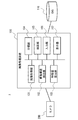
- FIG. 2 shows the configuration of the image processing apparatus 100 according to the present embodiment.
- the image processing device 100 constitutes the image processing system 1 together with the camera 200 and the database (DB) 110.
- the image processing system 1 including the image processing device 100 is a system for classifying and searching states such as posture and behavior of a person based on the skeleton structure of the person estimated from the image.
- the image processing device 100 also functions as an image selection device.
- the camera 200 is an image pickup unit such as a surveillance camera that generates a two-dimensional image.
- the camera 200 is installed at a predetermined location and captures a person or the like in the imaging region from the installation location.
- the camera 200 is directly connected so that the captured image (video) can be output to the image processing device 100, or is connected via a network or the like.
- the camera 200 may be provided inside the image processing device 100.
- the database 110 is a database that stores information (data), processing results, and the like necessary for processing of the image processing apparatus 100.
- the database 110 includes an image acquired by the image acquisition unit 101, a detection result of the skeletal structure detection unit 102, data for machine learning, a feature amount calculated by the feature amount calculation unit 103, a classification result of the classification unit 104, and a search unit 105. The search results etc. of are memorized.
- the database 110 is directly connected to the image processing device 100 so that data can be input / output as needed, or is connected via a network or the like.
- the database 110 may be provided inside the image processing device 100 as a non-volatile memory such as a flash memory, a hard disk device, or the like.
- the image processing device 100 includes an image acquisition unit 101, a skeleton structure detection unit 102, a feature amount calculation unit 103, a classification unit 104, a search unit 105, an input unit 106, and a display unit 107. ..
- the configuration of each part (block) is an example, and may be composed of other parts as long as the method (operation) described later is possible.
- the image processing device 100 is realized by, for example, a computer device such as a personal computer or a server that executes a program, but it may be realized by one device or by a plurality of devices on a network. good.
- the input unit 106, the display unit 107, and the like may be used as an external device.
- both the classification unit 104 and the search unit 105 may be provided, or only one of them may be provided.
- Both or one of the classification unit 104 and the search unit 105 is a recognition unit that performs recognition processing of the state of a person.
- the image acquisition unit 101 acquires a two-dimensional image including a person captured by the camera 200.
- the image acquisition unit 101 acquires, for example, an image including a person (a video including a plurality of images) captured by the camera 200 during a predetermined monitoring period.
- an image including a person prepared in advance may be acquired from the database 110 or the like.
- the skeleton structure detection unit 102 detects the two-dimensional skeleton structure of a person in the image based on the acquired two-dimensional image.
- the skeleton structure detection unit 102 detects the skeleton structure of all the persons recognized in the acquired image.
- the skeleton structure detection unit 102 detects the skeleton structure of a person based on the characteristics such as the joints of the person to be recognized by using the skeleton estimation technique using machine learning.
- the skeleton structure detection unit 102 uses, for example, a skeleton estimation technique such as OpenPose of Non-Patent Document 1.
- the feature amount calculation unit 103 calculates the feature amount of the detected two-dimensional skeletal structure, associates the calculated feature amount with the image to be processed, and stores it in the database 110.
- the feature amount of the skeletal structure indicates the characteristics of the skeleton of the person, and is an element for classifying or searching the state of the person based on the skeleton of the person. Usually, this feature quantity includes a plurality of parameters (for example, classification elements described later).
- the feature amount may be an entire feature amount of the skeletal structure, a partial feature amount of the skeletal structure, or a plurality of feature amounts such as each part of the skeletal structure.
- the feature amount may be calculated by any method such as machine learning or normalization, and the minimum value or the maximum value may be obtained as the normalization.
- the feature amount is a feature amount obtained by machine learning the skeletal structure, a size on an image of the skeletal structure from the head to the foot, and the like.
- the size of the skeleton structure is the vertical height and area of the skeleton region including the skeleton structure on the image.
- the vertical direction (height direction or vertical direction) is a vertical direction (Y-axis direction) in the image, and is, for example, a direction perpendicular to the ground (reference plane).
- the left-right direction (horizontal direction) is a left-right direction (X-axis direction) in the image, and is, for example, a direction parallel to the ground.
- a feature amount having robustness for the classification and search processing it is preferable to use a feature amount having robustness for the classification and search processing.
- a robust feature amount may be used for the orientation or body shape of the person. It depends on the orientation and body shape of the person by learning the skeleton of a person who is facing in various directions with the same posture and the skeleton of a person with various body shapes in the same posture, and by extracting the characteristics of the skeleton only in the vertical direction. It is possible to obtain a feature amount that does not.
- the classification unit 104 classifies (clusters) a plurality of skeletal structures stored in the database 110 based on the similarity of the feature amounts of the skeletal structures. It can be said that the classification unit 104 classifies the states of a plurality of persons based on the feature amount of the skeletal structure as the process of recognizing the state of the person. Similarity is the distance between features of the skeletal structure.
- the classification unit 104 may be classified according to the similarity of the features of the whole skeleton structure, or may be classified according to the similarity of the features of a part of the skeleton structure, and the first part of the skeleton structure (for example, for example). It may be classified according to the similarity of the features of both hands) and the second part (for example, both feet).
- the posture of the person may be classified based on the feature amount of the skeletal structure of the person in each image, or the behavior of the person based on the change in the feature amount of the skeletal structure of the person in a plurality of consecutive images in time series. May be classified. That is, the classification unit 104 can classify the state of the person including the posture and behavior of the person based on the feature amount of the skeletal structure. For example, the classification unit 104 targets a plurality of skeletal structures in a plurality of images captured during a predetermined monitoring period. The classification unit 104 obtains the degree of similarity between the features to be classified, and classifies the skeletal structures having a high degree of similarity into the same cluster (group with similar postures). As with the search, the user may be able to specify the classification conditions. The classification unit 104 stores the classification result of the skeletal structure in the database 110 and displays it on the display unit 107.
- the search unit 105 searches for a skeleton structure having a high degree of similarity to the feature amount of the search query (query state) from a plurality of skeleton structures stored in the database 110. It can be said that the search unit 105 searches for the state of a person who corresponds to the search condition (query state) from among the states of a plurality of people based on the feature amount of the skeleton structure as the process of recognizing the state of the person. Similar to classification, similarity is the distance between features of the skeletal structure.
- the search unit 105 may search by the similarity of the features of the whole skeleton structure, or may search by the similarity of the features of a part of the skeleton structure, and may search by the similarity of the first part of the skeleton structure (for example,). You may search by the similarity of the features of both hands) and the second part (for example, both feet).
- the posture of the person may be searched based on the feature amount of the skeletal structure of the person in each image, or the behavior of the person may be searched based on the change of the feature amount of the skeletal structure of the person in a plurality of consecutive images in time series. You may search for.
- the search unit 105 can search the state of the person including the posture and behavior of the person based on the feature amount of the skeletal structure. For example, the search unit 105 searches for features of a plurality of skeletal structures in a plurality of images captured during a predetermined monitoring period, similarly to the classification target. Further, the skeleton structure (posture) specified by the user from the classification results displayed by the classification unit 104 is used as a search query (search key). Not limited to the classification result, the search query may be selected from a plurality of unclassified skeleton structures, or the user may input the skeleton structure to be the search query.
- the search unit 105 searches for a feature amount having a high degree of similarity to the feature amount of the skeleton structure of the search query from the feature amount of the search target.
- the search unit 105 stores the search result of the feature amount in the database 110 and displays it on the display unit 107.
- the input unit 106 is an input interface for acquiring information input from a user who operates the image processing device 100.
- a user is a monitor who monitors a person in a suspicious state from an image of a surveillance camera.
- the input unit 106 is, for example, a GUI (Graphical User Interface), and information according to a user's operation is input from an input device such as a keyboard, a mouse, or a touch panel.
- the input unit 106 accepts the skeleton structure of a designated person from the skeleton structures (postures) classified by the classification unit 104 as a search query.
- the display unit 107 is a display unit that displays the result of the operation (processing) of the image processing device 100, and is, for example, a display device such as a liquid crystal display or an organic EL (ElectroLuminescence) display.
- the display unit 107 displays the classification result of the classification unit 104 and the search result of the search unit 105 on the GUI according to the degree of similarity and the like.
- FIG. 39 is a diagram showing a hardware configuration example of the image processing device 100.
- the image processing device 100 includes a bus 1010, a processor 1020, a memory 1030, a storage device 1040, an input / output interface 1050, and a network interface 1060.
- the bus 1010 is a data transmission path for the processor 1020, the memory 1030, the storage device 1040, the input / output interface 1050, and the network interface 1060 to transmit and receive data to each other.
- the method of connecting the processors 1020 and the like to each other is not limited to the bus connection.
- the processor 1020 is a processor realized by a CPU (Central Processing Unit), a GPU (Graphics Processing Unit), or the like.
- the memory 1030 is a main storage device realized by a RAM (RandomAccessMemory) or the like.
- the storage device 1040 is an auxiliary storage device realized by an HDD (Hard Disk Drive), SSD (Solid State Drive), memory card, ROM (Read Only Memory), or the like.
- the storage device 1040 stores a program module that realizes each function of the image processing device 100 (for example, an image acquisition unit 101, a skeleton structure detection unit 102, a feature amount calculation unit 103, a classification unit 104, a search unit 105, and an input unit 106). doing.
- the processor 1020 reads each of these program modules into the memory 1030 and executes them, each function corresponding to the program module is realized.
- the storage device 1040 may also function as a database 110.
- the input / output interface 1050 is an interface for connecting the image processing device 100 and various input / output devices.
- the image processing device 100 may connect to the database 110 via the input / output interface 1050.
- the network interface 1060 is an interface for connecting the image processing device 100 to the network.
- This network is, for example, LAN (Local Area Network) or WAN (Wide Area Network).
- the method of connecting the network interface 1060 to the network may be a wireless connection or a wired connection.
- the image processing device 100 may communicate with the camera 200 via the network interface 1060.
- the image processing device 100 may connect to the database 110 via the network interface 1060.
- FIG. 3 to 5 show the operation of the image processing apparatus 100 according to the present embodiment.
- FIG. 3 shows a flow from image acquisition to search processing in the image processing apparatus 100
- FIG. 4 shows a flow of classification processing (S104) in FIG. 3
- FIG. 5 shows a flow of search processing (S105) in FIG. It shows the flow.
- the image processing device 100 acquires an image from the camera 200 (S101).
- the image acquisition unit 101 acquires an image of a person in order to classify or search from the skeleton structure, and stores the acquired image in the database 110.
- the image acquisition unit 101 acquires, for example, a plurality of images captured during a predetermined monitoring period, and performs subsequent processing on all the persons included in the plurality of images.
- FIG. 6 shows an example of detecting a skeletal structure.
- an image acquired from a surveillance camera or the like contains a plurality of persons, and the skeleton structure is detected for each person included in the image.
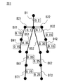
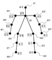
- FIG. 7 shows the skeleton structure of the human body model 300 detected at this time
- FIGS. 8 to 10 show an example of detecting the skeleton structure.
- the skeleton structure detection unit 102 detects the skeleton structure of the human body model (two-dimensional skeleton model) 300 as shown in FIG. 7 from the two-dimensional image by using a skeleton estimation technique such as OpenPose.
- the human body model 300 is a two-dimensional model composed of key points such as joints of a person and bones connecting the key points.
- the skeleton structure detection unit 102 extracts feature points that can be key points from an image, and detects each key point of a person by referring to information obtained by machine learning the image of the key points.
- the key points of the person are head A1, neck A2, right shoulder A31, left shoulder A32, right elbow A41, left elbow A42, right hand A51, left hand A52, right hip A61, left hip A62, and right knee A71.
- Left knee A72, right foot A81, left foot A82 are detected.
- Bone B31 and B32 connecting the elbow A41 and the left elbow A42, respectively, connecting the right elbow A41 and the left elbow A42 to the right hand A51 and the left hand A52, respectively, and connecting the neck A2 to the right waist A61 and the left waist A62, respectively.
- B72 is detected.
- the skeleton structure detection unit 102 stores the detected skeleton structure of the person in the database 110.
- FIG. 8 is an example of detecting an upright person.
- an upright person is imaged from the front, and bones B1, bone B51 and bone B52, bones B61 and bone B62, bones B71 and bone B72 viewed from the front are detected without overlapping, respectively, and the right foot.
- Bone B61 and Bone B71 are slightly bent more than Bone B62 and Bone B72 of the left foot.
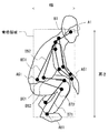
- FIG. 9 is an example of detecting a person in a crouched state.
- a crouching person is imaged from the right side, bone B1, bone B51 and bone B52, bone B61 and bone B62, bone B71 and bone B72, respectively, viewed from the right side, and bone B61 on the right foot.
- the bone B71 and the bone B62 and the bone B72 of the left foot are greatly bent and overlapped.
- FIG. 10 is an example of detecting a person who is sleeping.
- a sleeping person is imaged from diagonally left front, and bone B1, bone B51 and bone B52, bone B61 and bone B62, bone B71 and bone B72 viewed from diagonally left front are detected, respectively, and the right foot.
- the bones B61 and B71 of the left foot and the bones B62 and B72 of the left foot are bent and overlapped.
- the image processing apparatus 100 calculates the detected feature amount of the skeletal structure (S103). For example, when the height or area of the skeleton region is used as the feature amount, the feature amount calculation unit 103 extracts a region including the skeleton structure and obtains the height (number of pixels) or area (pixel area) of the region. The height and area of the skeletal region can be obtained from the coordinates of the end of the extracted skeleton region and the coordinates of the key points at the ends. The feature amount calculation unit 103 stores the obtained feature amount of the skeletal structure in the database 110.
- the feature amount of this skeletal structure is also used as posture information indicating the posture of a person. Further, the feature amount of this skeletal structure is the reliability of the feature amount and the reliability of the feature amount stored in the database 110 is the certainty that the feature amount is the feature amount (that is, the probability that the estimation result of the posture is correct). Shows. When the reliability of a certain feature is high, the probability of that feature is high.
- the reliability of the feature amount is calculated by using, for example, the number of key points used when setting the feature amount of the skeleton structure and the reliability of the key points. For example, as the number of joints increases, the reliability of the feature quantity increases. Further, the higher the reliability of the key point, the higher the reliability of the feature quantity.
- the skeletal region including all bones is extracted from the skeletal structure of an upright person.
- the upper end of the skeletal region is the key point A1 of the head
- the lower end of the skeletal region is the key point A82 of the left foot
- the left end of the skeletal region is the key point A41 of the right elbow
- the right end of the skeletal region is the key point A52 of the left hand. .. Therefore, the height of the skeleton region is obtained from the difference between the Y coordinates of the key point A1 and the key point A82.
- the width of the skeleton region is obtained from the difference between the X coordinates of the key point A41 and the key point A52, and the area is obtained from the height and width of the skeleton region.
- the skeletal region including all bones is extracted from the skeletal structure of a crouched person.
- the upper end of the skeletal region is the key point A1 of the head
- the lower end of the skeletal region is the key point A81 of the right foot
- the left end of the skeletal region is the key point A61 of the right hip
- the right end of the skeletal region is the key point A51 of the right hand. .. Therefore, the height of the skeleton region is obtained from the difference between the Y coordinates of the key point A1 and the key point A81.
- the width of the skeleton region is obtained from the difference between the X coordinates of the key point A61 and the key point A51, and the area is obtained from the height and width of the skeleton region.
- a skeletal region including all bones is extracted from the skeletal structure of a person who has fallen in the left-right direction of the image.
- the upper end of the skeleton region is the key point A32 of the left shoulder
- the lower end of the skeleton region is the key point A52 of the left hand
- the left end of the skeleton region is the key point A51 of the right hand
- the right end of the skeleton region is the key point A82 of the left foot. Therefore, the height of the skeleton region is obtained from the difference between the Y coordinates of the key point A32 and the key point A52.
- the width of the skeleton region is obtained from the difference between the X coordinates of the key point A51 and the key point A82, and the area is obtained from the height and width of the skeleton region.
- the image processing apparatus 100 performs classification processing (S104).
- the classification unit 104 calculates the similarity of the calculated feature amount of the skeletal structure (S111), and classifies the skeletal structure based on the calculated feature amount (S112). ..
- the classification unit 104 obtains the similarity of the features between all the skeletal structures stored in the database 110 to be classified, and classifies (clusters) the skeletal structures (postures) having the highest similarity into the same cluster. .. Further, the similarity between the classified clusters is obtained and classified, and the classification is repeated until a predetermined number of clusters are obtained.
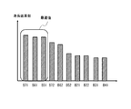
- FIG. 11 shows an image of the classification result of the feature amount of the skeletal structure.
- the feature quantities of the plurality of skeletal structures are classified into three clusters C1 to C3.
- the clusters C1 to C3 correspond to each posture such as a standing posture, a sitting posture, and a sleeping posture, and the skeletal structure (person) is classified for each similar posture.
- various classification methods can be used by classifying based on the feature amount of the skeletal structure of a person.
- the classification method may be set in advance or may be arbitrarily set by the user. Further, the classification may be performed by the same method as the search method described later. That is, it may be classified according to the same classification conditions as the search conditions.
- the classification unit 104 classifies by the following classification method. Any classification method may be used, or an arbitrarily selected classification method may be combined.
- Classification method 1 Classification by multiple layers Classification by skeletal structure of the whole body, classification by skeletal structure of upper body and lower body, classification by skeletal structure of arms and legs, etc. are classified in a hierarchical combination. That is, the classification may be performed based on the feature amounts of the first portion and the second portion of the skeletal structure, and further, the feature amounts of the first portion and the second portion may be weighted and classified.
- Classification method 2 Classification by multiple images along the time series Classification is based on the feature amount of the skeletal structure in a plurality of images continuous in the time series.
- the feature quantities may be stacked in the time series direction and classified based on the cumulative value. Further, it may be classified based on the change (change amount) of the feature amount of the skeletal structure in a plurality of continuous images.
- Classification method 3 Classification ignoring the left and right sides of the skeletal structure Classify the skeletal structures whose right and left sides are opposite to each other as the same skeletal structure.
- the classification unit 104 displays the classification result of the skeletal structure (S113).
- the classification unit 104 acquires images of necessary skeleton structures and people from the database 110, and displays the skeleton structure and people on the display unit 107 for each posture (cluster) similar as a classification result.
- FIG. 12 shows a display example when the postures are classified into three. For example, as shown in FIG. 12, the posture regions WA1 to WA3 for each posture are displayed in the display window W1, and the skeletal structure and the person (image) of the posture corresponding to each of the posture regions WA1 to WA3 are displayed.
- the posture region WA1 is, for example, a display region of a standing posture, and displays a skeletal structure and a person similar to a standing posture classified into cluster C1.
- the posture area WA2 is, for example, a sitting posture display area, and displays a skeletal structure and a person similar to the sitting posture classified into cluster C2.
- the posture area WA3 is, for example, a display area of a sleeping posture, and displays a skeletal structure and a person similar to the sleeping posture classified into cluster C2.
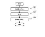
- the image processing apparatus 100 performs a search process (S105).
- the search unit 105 accepts the input of the search condition (S121) and searches for the skeleton structure based on the search condition (S122).
- the search unit 105 receives input of a search query, which is a search condition, from the input unit 106 according to the user's operation.
- the user specifies (selects) the skeleton structure of the posture to be searched from the posture areas WA1 to WA3 displayed in the display window W1. ..
- the search unit 105 uses the skeleton structure specified by the user as a search query to search for a skeleton structure having a high degree of similarity in the feature amount from all the skeleton structures stored in the database 110 to be searched.
- the search unit 105 calculates the similarity between the feature amount of the skeletal structure of the search query and the feature amount of the skeletal structure to be searched, and extracts the skeletal structure whose calculated similarity is higher than a predetermined threshold value.
- the feature amount of the skeleton structure of the search query the feature amount calculated in advance may be used, or the feature amount obtained at the time of search may be used.
- the search query may be input by moving each part of the skeleton structure according to the operation of the user, or the posture demonstrated by the user in front of the camera may be used as the search query.
- search method can be used by searching based on the feature amount of the skeletal structure of the person.
- the search method may be preset or may be arbitrarily set by the user.
- the search unit 105 searches by the following search method. Either search method may be used, or an arbitrarily selected search method may be combined.
- a plurality of search methods search conditions may be combined and searched by a logical expression (for example, AND (logical product), OR (logical sum), NOT (negation)).
- search condition may be searched as "(posture in which the right hand is raised) AND (posture in which the left foot is raised)".
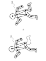
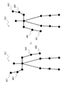
- (Search method 1) Search by only the feature amount in the height direction By searching using only the feature amount in the height direction of the person, the influence of the lateral change of the person can be suppressed, and the direction of the person and the person can be suppressed. Improves robustness against changes in body shape. For example, as in the skeletal structures 501 to 503 of FIG. 13, even if the orientation and body shape of the person are different, the feature amount in the height direction does not change significantly. Therefore, in the skeletal structures 501 to 503, it can be determined that the postures are the same at the time of searching (at the time of classification).
- search method 2 If a part of the person's body is hidden in the partial search image, search using only the information of the recognizable part. For example, as in the skeletal structures 511 and 512 of FIG. 14, even if the key point of the left foot cannot be detected due to the hiding of the left foot, the feature amount of other detected key points can be used for the search. Therefore, in the skeletal structures 511 and 512, it can be determined that the postures are the same at the time of searching (at the time of classification). That is, it is possible to perform classification and search using the features of some key points instead of all the key points. In the examples of the skeletal structures 521 and 522 of FIG.
- the feature quantities of the key points of the upper body (A1, A2, A31, A32, A41, A42, A51, A52) are used as the search query. Therefore, it can be determined that the posture is the same. Further, the portion (feature point) to be searched may be weighted and searched, or the threshold value for determining the similarity may be changed. When a part of the body is hidden, the hidden part may be ignored and the search may be performed, or the hidden part may be added to the search. By searching including hidden parts, it is possible to search for postures in which the same part is hidden.
- (Search method 3) Search ignoring the left and right sides of the skeleton structure Search for the same skeleton structure on the right and left sides of the person.
- the posture in which the right hand is raised and the posture in which the left hand is raised can be searched (classified) as the same posture.
- the skeletal structure 531 and the skeletal structure 532 have different positions of the right hand key point A51, the right elbow key point A41, the left hand key point A52, and the left elbow key point A42, but other key points. The position of is the same.
- Search method 4 Search by features in the vertical and horizontal directions After searching only with the features in the vertical direction (Y-axis direction) of the person, the obtained results are further added to the horizontal direction (X-axis direction) of the person. Search using the features of.
- search method 5 Search by multiple images along the time series Search based on the feature quantity of the skeletal structure in a plurality of images continuous in the time series.
- the feature quantities may be stacked in the time series direction and searched based on the cumulative value.
- the search may be performed based on the change (change amount) of the feature amount of the skeletal structure in a plurality of consecutive images.
- the search unit 105 displays the search result of the skeletal structure (S123).
- the search unit 105 acquires images of necessary skeleton structures and people from the database 110, and displays the skeleton structures and people obtained as search results on the display unit 107. For example, when multiple search queries (search conditions) are specified, the search results are displayed for each search query.
- FIG. 17 shows a display example when a search is performed using three search queries (postures). For example, as shown in FIG. 17, in the display window W2, the skeleton structure and the person of the search queries Q10, Q20, and Q30 specified at the left end are displayed, and each search query is displayed on the right side of the search queries Q10, Q20, and Q30.
- the skeletal structures and people of the search results Q11, Q21, and Q31 are displayed side by side.
- the order in which the search results are displayed side by side from the side of the search query may be the order in which the corresponding skeletal structure is found or the order in which the degree of similarity is high.
- the weighted and calculated similarity may be displayed in order. It may be displayed in the order of similarity calculated from only the part (feature point) selected by the user. Further, the images (frames) before and after the time series may be cut out and displayed for a certain period of time, centering on the image (frame) of the search result.
- Search method 6 In this search method, a plurality of searched images are set using the reliability of the posture information of the images.
- FIG. 40 is a diagram showing an example of the functional configuration of the search unit 105 according to this search method.
- the search unit 105 includes a query acquisition unit 610, a search information acquisition unit 620, a selection unit 630, and a display control unit 640.
- the query acquisition unit 610 acquires posture information (hereinafter referred to as query posture information) indicating the posture of a person, which is information to be a query.
- posture information hereinafter referred to as query posture information
- the search information acquisition unit 620 acquires a plurality of search posture information.
- the search posture information is posture information of an image to be searched (hereinafter referred to as a target image), and is stored in the database 110 for each of a plurality of target images.
- the selection unit 630 selects two or more search posture information whose similarity to the query posture information satisfies the criteria among the plurality of search posture information.
- This selection process is substantially a process of selecting a target image similar to an image corresponding to the posture information for query (hereinafter referred to as a query image).
- the display control unit 640 displays the target image corresponding to each of the two or more search posture information selected by the selection unit 630 on the display unit 107, and displays the display position of these target images on the reliability of the search posture information. Set using. This reliability is stored in the database 110 as described above.
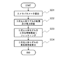
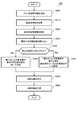
- FIG. 41 is a flowchart showing an example of the processing performed by the search unit 105 according to the present search method.
- the query acquisition unit 610 acquires query posture information (step S300).
- the query acquisition unit 610 acquires query posture information from the database 110.
- the user inputs an input for specifying the query image to the query acquisition unit 610.
- the query acquisition unit 610 reads the query posture information corresponding to the query image from the database 110.
- the query acquisition unit 610 may acquire an image to be a query from an external device.
- the skeletal structure detection unit 102 and the feature amount calculation unit 103 process this image to calculate the feature amount of the skeletal structure. Then, the query acquisition unit 610 acquires the feature amount of this skeletal structure as the posture information for query.
- the search information acquisition unit 620 acquires a plurality of posture information stored in the database 110 as search information (step S310).
- the selection unit 630 selects two or more search posture information having a similarity to the query posture information as a criterion from the plurality of search posture information (step S320).
- the processing performed here is performed using, for example, at least one of the above-mentioned search methods 1 to 5, but may be performed using another method.
- the display control unit 640 reads out the target image corresponding to the search posture information selected in step S320 from the database 110. Since two or more search posture information are selected in step S320, the display control unit 640 also reads two or more target images from the database 110. At this time, the display control unit 640 also reads the reliability of each target image from the database 110 (step S330).
- the display control unit 640 sets the display position of each target image using the reliability of the target image (step S340).
- the reliability indicates the probability that the posture estimation result is correct. Therefore, if the reliability is high, the possibility that the target image is similar to the query image is high. Therefore, if the display position of the target image is set using the reliability of the target image, the user can be made to recognize the influence of the reliability of each target image on the validity of the selection result in step S320.
- the display control unit 640 causes the display unit 107 to display the target image read in step S330. At this time, the display control unit 640 displays each target image at the display position determined in step S340 (step S350).
- the selection unit 630 stores the selection result of step S320 in the database 110 (step S360).
- the selection unit 630 may store the target image read in step S330 in the database 110 as one cluster, or the target image already stored in the database 110 may be stored in the database 110 as a query image. It may be associated with a flag indicating that they are similar.
- FIG. 42 is a diagram showing an example of a method for determining a display position of a target image, which is performed in step S340.
- the display control unit 640 displays the target images on the display unit 107 in descending order of reliability.
- the order of the target images is not limited to this example.
- the display control unit 640 causes the display unit 107 to display the target image together with the reliability of the search posture information of the target image. By doing so, the user can directly confirm the reliability of the selected target image, and thus can grasp the reliability required to obtain a reasonable selection result.
- FIG. 43 is a flowchart showing a modification 1 of FIG. 41.
- the display control unit 640 determines the display position of the target image, in addition to the reliability of the target image, the similarity between the target image and the query image, that is, the posture information for search and the query It is the same as in FIG. 41 except that the similarity of the posture information is also used (step S342).
- the display control unit 640 determines the order of the target images using the above-mentioned reliability and similarity. For example, the display control unit 640 calculates the evaluation value using the above-mentioned function with the reliability and the similarity as parameters, and displays the target images in descending order of the evaluation value (or in ascending order).
- An example of this function is to calculate the sum of reliability and similarity after adding predetermined weighting coefficients to each of them.
- FIG. 44 is a flowchart showing a modification 2 of FIG. 41.
- the display control unit 640 determines the display position of the target image on condition that a predetermined condition is satisfied (step S332: Yes), in addition to the reliability of the target image.
- the similarity between the target image and the query image is also used instead of this reliability (step S344).
- step S342 The process when the similarity between the target image and the query image is used in addition to the reliability of the target image is the same as step S342 in FIG. 43. Further, the process when the similarity between the target image and the query image is used instead of the reliability of the target image is the same as step S340 in FIG. 41 except that the similarity is used.
- the present embodiment it is possible to detect the skeletal structure of a person from a two-dimensional image and perform classification and search based on the feature amount of the detected skeletal structure. As a result, it is possible to classify by similar postures having a high degree of similarity, and it is possible to search for similar postures having a high degree of similarity with a search query (search key).
- search key search key
- the posture of the person in the image can be grasped without the user specifying the posture or the like. Since the user can specify the posture of the search query from the classification results, the desired posture can be searched even if the user does not know the posture to be searched in detail in advance. For example, since it is possible to perform classification and search on the condition of the whole or part of the skeleton structure of a person, flexible classification and search is possible.
- the display position of the target image is set using the reliability of the target image. Therefore, the user can be made aware of the influence of the reliability of each target image on the validity of the selection result.
- FIG. 18 shows the configuration of the image processing apparatus 100 according to the present embodiment.
- the image processing apparatus 100 further includes a height calculation unit 108 in addition to the configuration of the first embodiment.
- the feature amount calculation unit 103 and the height calculation unit 108 may be combined into one processing unit.
- the height calculation unit (height estimation unit) 108 calculates the height of the person in the two-dimensional image when standing upright (referred to as the number of height pixels) based on the two-dimensional skeleton structure detected by the skeleton structure detection unit 102 (referred to as the number of height pixels). presume. It can also be said that the number of height pixels is the height of the person in the two-dimensional image (the length of the whole body of the person in the two-dimensional image space). The height calculation unit 108 obtains the number of height pixels (number of pixels) from the length (length on the two-dimensional image space) of each bone of the detected skeleton structure.
- specific examples 1 to 3 are used as a method for obtaining the number of height pixels.
- any of the methods of Specific Examples 1 to 3 may be used, or a plurality of arbitrarily selected methods may be used in combination.
- the number of height pixels is obtained by summing the lengths of the bones from the head to the foot among the bones of the skeletal structure. If the skeleton structure detection unit 102 (skeleton estimation technique) does not output the top of the head and the feet, it can be corrected by multiplying by a constant as necessary.
- the number of height pixels is calculated using a human body model showing the relationship between the length of each bone and the length of the whole body (height on a two-dimensional image space).
- the number of height pixels is calculated by fitting (fitting) a three-dimensional human body model to a two-dimensional skeleton structure.
- the feature amount calculation unit 103 of the present embodiment is a normalization unit that normalizes the skeletal structure (skeleton information) of a person based on the calculated number of height pixels of the person.
- the feature amount calculation unit 103 stores the feature amount (normalized value) of the normalized skeletal structure in the database 110.
- the feature amount calculation unit 103 normalizes the height of each key point (feature point) included in the skeleton structure on the image by the number of height pixels.
- the height direction is the vertical direction (Y-axis direction) in the two-dimensional coordinate (XY coordinate) space of the image. In this case, the height of the key point can be obtained from the value (number of pixels) of the Y coordinate of the key point.
- the height direction may be the direction of the vertical axis perpendicular to the ground (reference plane) in the three-dimensional coordinate space in the real world, and the direction of the vertical projection axis projected onto the two-dimensional coordinate space (vertical projection direction).
- the height of the key point is the vertical projection axis obtained by projecting the axis perpendicular to the ground in the real world onto the two-dimensional coordinate space based on the camera parameters, and the value along this vertical projection axis (number of pixels). ) Can be obtained.
- the camera parameters are image imaging parameters, and for example, the camera parameters are the posture, position, imaging angle, focal length, and the like of the camera 200.
- the camera 200 can take an image of an object whose length and position are known in advance, and obtain camera parameters from the image. Distortion occurs at both ends of the captured image, and the vertical direction of the real world may not match the vertical direction of the image. On the other hand, by using the parameters of the camera that took the image, you can see how much the vertical direction in the real world is tilted in the image. Therefore, by normalizing the value of the key point along the vertical projection axis projected in the image based on the camera parameters by height, it is possible to quantify the key point in consideration of the deviation between the real world and the image. can.
- the left-right direction is the left-right direction (X-axis direction) in the two-dimensional coordinate (XY coordinates) space of the image, or the direction parallel to the ground in the three-dimensional coordinate space in the real world. Is the direction projected onto the two-dimensional coordinate space.
- 19 to 23 show the operation of the image processing device 100 according to the present embodiment.
- 19 shows a flow from image acquisition to search processing in the image processing apparatus 100
- FIGS. 20 to 22 show the flow of specific examples 1 to 3 of the height pixel number calculation process (S201) of FIG. 23 shows the flow of the normalization process (S202) of FIG.
- the height pixel number calculation process (S201) and the normalization process (S202) are performed as the feature amount calculation process (S103) in the first embodiment. Others are the same as those in the first embodiment.
- the image processing device 100 performs height pixel number calculation processing based on the detected skeleton structure (S201) following the image acquisition (S101) and the skeleton structure detection (S102).
- the height of the skeleton structure of the person standing upright in the image is the height pixel number (h)
- the height of each key point of the skeleton structure in the state of the person in the image is the key point. Let it be the height (yi).
- specific examples 1 to 3 of the height pixel number calculation process will be described.
- Specific Example 1 the number of height pixels is obtained using the length of the bone from the head to the foot.
- the height calculation unit 108 acquires the length of each bone (S211) and totals the lengths of the acquired bones (S212).
- the height calculation unit 108 acquires the length of the bone on the two-dimensional image of the foot from the head of the person, and obtains the number of height pixels. That is, from the image in which the skeletal structure is detected, among the bones of FIG. 24, bone B1 (length L1), bone B51 (length L21), bone B61 (length L31) and bone B71 (length L41), or , Bone B1 (length L1), bone B52 (length L22), bone B62 (length L32), and bone B72 (length L42) are acquired. The length of each bone can be obtained from the coordinates of each key point in the two-dimensional image.
- the longer value is taken as the number of height pixels. That is, each bone has the longest length in the image when it is imaged from the front, and it is displayed short when it is tilted in the depth direction with respect to the camera. Therefore, it is more likely that the longer bone is imaged from the front, which is considered to be closer to the true value. Therefore, it is preferable to select the longer value.
- bone B1, bone B51 and bone B52, bone B61 and bone B62, bone B71 and bone B72 are detected without overlapping.
- the total of these bones, L1 + L21 + L31 + L41 and L1 + L22 + L32 + L42, is obtained, and for example, the value obtained by multiplying L1 + L22 + L32 + L42 on the left foot side where the detected bone length is long by a correction constant is taken as the height pixel number.
- bone B1, bone B51 and bone B52, bone B61 and bone B62, bone B71 and bone B72 are detected, respectively, and the right foot bone B61 and bone B71 and the left foot bone B62 and bone B72 overlap each other. ..
- the total of these bones, L1 + L21 + L31 + L41 and L1 + L22 + L32 + L42, is obtained, and for example, the value obtained by multiplying L1 + L21 + L31 + L41 on the right foot side where the detected bone length is long by a correction constant is taken as the height pixel number.
- bone B1, bone B51 and bone B52, bone B61 and bone B62, bone B71 and bone B72 are detected, respectively, and the right foot bone B61 and bone B71 and the left foot bone B62 and bone B72 overlap each other. ..
- the total of these bones, L1 + L21 + L31 + L41 and L1 + L22 + L32 + L42, is obtained, and for example, the value obtained by multiplying L1 + L22 + L32 + L42 on the left foot side where the detected bone length is long by a correction constant is taken as the height pixel number.
- the height can be calculated by summing the lengths of the bones from the head to the feet, so the number of height pixels can be calculated by a simple method.
- the number of height pixels can be accurately calculated even when the entire person is not always shown in the image, such as when crouching down. Can be estimated.
- Specific Example 2 the number of height pixels is obtained using a two-dimensional skeleton model showing the relationship between the length of the bone included in the two-dimensional skeleton structure and the length of the whole body of the person in the two-dimensional image space.
- FIG. 28 is a human body model (two-dimensional skeleton model) 301 showing the relationship between the length of each bone in the two-dimensional image space and the length of the whole body in the two-dimensional image space used in the second embodiment.
- the relationship between the length of each bone of an average person and the length of the whole body is associated with each bone of the human body model 301.
- the length of the bone B1 of the head is the length of the whole body ⁇ 0.2 (20%)
- the length of the bone B41 of the right hand is the length of the whole body ⁇ 0.15 (15%)
- the length of the right foot is the length of the whole body ⁇ 0.25 (25%).
- the average whole body length can be obtained from the length of each bone.
- a human body model may be prepared for each attribute of the person such as age, gender, and nationality. As a result, the length (height) of the whole body can be appropriately obtained according to the attributes of the person.
- the height calculation unit 108 acquires the length of each bone (S221).
- the height calculation unit 108 acquires the lengths (lengths in the two-dimensional image space) of all the bones in the detected skeleton structure.
- FIG. 29 is an example in which a person in a crouched state is imaged from diagonally right behind and the skeletal structure is detected. In this example, since the face and left side of the person are not shown, the bones of the head, the left arm, and the bones of the left hand cannot be detected. Therefore, the lengths of the detected bones B21, B22, B31, B41, B51, B52, B61, B62, B71, and B72 are acquired.
- the height calculation unit 108 calculates the number of height pixels from the length of each bone based on the human body model (S222).
- the height calculation unit 108 refers to the human body model 301 showing the relationship between each bone and the length of the whole body as shown in FIG. 28, and obtains the number of height pixels from the length of each bone. For example, since the length of the bone B41 on the right hand is the length of the whole body ⁇ 0.15, the number of height pixels based on the bone B41 is obtained from the length of the bone B41 / 0.15. Further, since the length of the bone B71 of the right foot is the length of the whole body ⁇ 0.25, the number of height pixels based on the bone B71 is obtained from the length of the bone B71 / 0.25.
- the human body model referred to at this time is, for example, a human body model of an average person, but a human body model may be selected according to the attributes of the person such as age, gender, and nationality. For example, when a person's face is shown in the captured image, the attribute of the person is identified based on the face, and the human body model corresponding to the identified attribute is referred to. It is possible to recognize a person's attributes from the facial features of the image by referring to the information obtained by machine learning the face for each attribute. Further, when the attribute of the person cannot be identified from the image, the human body model of the average person may be used.
- the number of height pixels calculated from the length of the bone may be corrected by the camera parameter. For example, when the camera is taken at a high position and looking down at a person, the horizontal length of the shoulder-width bones, etc. is not affected by the depression angle of the camera in the two-dimensional skeletal structure, but the vertical length of the neck-waist bones, etc. The length decreases as the depression angle of the camera increases. Then, the number of height pixels calculated from the horizontal length of the shoulder-width bones and the like tends to be larger than the actual number.
- the height calculation unit 108 calculates the optimum value of the number of height pixels as shown in FIG. 21 (S223).
- the height calculation unit 108 calculates the optimum value of the number of height pixels from the number of height pixels obtained for each bone. For example, as shown in FIG. 30, a histogram of the number of height pixels obtained for each bone is generated, and a large number of height pixels is selected from the histogram. That is, the number of height pixels longer than the others is selected from the plurality of height pixels obtained based on the plurality of bones. For example, the upper 30% is set as a valid value, and in FIG. 30, the number of height pixels by bones B71, B61, and B51 is selected.
- the average number of selected height pixels may be obtained as the optimum value, or the largest number of height pixels may be used as the optimum value. Since the height is calculated from the length of the bone in the 2D image, the length of the bone is taken from the front when the bone is not made from the front, that is, when the bone is tilted in the depth direction when viewed from the camera. It will be shorter than the case. Then, a value having a large number of height pixels is more likely to be captured from the front than a value having a small number of height pixels, and is a more plausible value. Therefore, a larger value is set as the optimum value.
- the number of height pixels is calculated based on the detected bones of the skeleton structure using a human body model showing the relationship between the bones in the two-dimensional image space and the length of the whole body, so that all the skeletons from the head to the feet are obtained. Even if is not obtained, the number of height pixels can be obtained from some bones. In particular, the number of height pixels can be estimated accurately by adopting a larger value among the values obtained from a plurality of bones.
- Specific Example 3 the two-dimensional skeletal structure is fitted to the three-dimensional human body model (three-dimensional skeletal model), and the skeletal vector of the whole body is obtained using the number of height pixels of the fitted three-dimensional human body model.
- the height calculation unit 108 first calculates the camera parameters based on the image captured by the camera 200 (S231).
- the height calculation unit 108 extracts an object whose length is known in advance from a plurality of images captured by the camera 200, and obtains a camera parameter from the size (number of pixels) of the extracted object.
- the camera parameters may be obtained in advance, and the obtained camera parameters may be acquired as needed.
- the height calculation unit 108 adjusts the arrangement and height of the three-dimensional human body model (S232).
- the height calculation unit 108 prepares a three-dimensional human body model for calculating the number of height pixels for the detected two-dimensional skeleton structure, and arranges the three-dimensional human body model in the same two-dimensional image based on the camera parameters.
- the "relative positional relationship between the camera and the person in the real world" is specified from the camera parameters and the two-dimensional skeleton structure. For example, assuming that the position of the camera is the coordinates (0, 0, 0), the coordinates (x, y, z) of the position where the person is standing (or sitting) are specified. Then, by assuming an image in which a three-dimensional human body model is placed at the same position (x, y, z) as the specified person and captured, the two-dimensional skeleton structure and the three-dimensional human body model are superimposed.
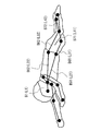
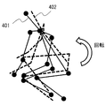
- FIG. 31 is an example in which a crouching person is imaged diagonally from the front left and the two-dimensional skeleton structure 401 is detected.
- the two-dimensional skeleton structure 401 has two-dimensional coordinate information. It is preferable that all bones are detected, but some bones may not be detected.
- a three-dimensional human body model 402 as shown in FIG. 32 is prepared.
- the three-dimensional human body model (three-dimensional skeleton model) 402 has three-dimensional coordinate information and is a model of a skeleton having the same shape as the two-dimensional skeleton structure 401.
- the prepared three-dimensional human body model 402 is arranged and superimposed on the detected two-dimensional skeleton structure 401.
- the height of the three-dimensional human body model 402 is adjusted so as to match the two-dimensional skeleton structure 401.
- the three-dimensional human body model 402 prepared at this time may be a model in a state close to the posture of the two-dimensional skeleton structure 401 as shown in FIG. 33, or may be a model in an upright state.
- a 3D human body model 402 of the estimated posture may be generated by using a technique of estimating the posture of the 3D space from the 2D image using machine learning. By learning the information of the joints in the 2D image and the joints in the 3D space, the 3D posture can be estimated from the 2D image.
- the height calculation unit 108 fits the three-dimensional human body model into the two-dimensional skeletal structure as shown in FIG. 22 (S233). As shown in FIG. 34, the height calculation unit 108 superimposes the three-dimensional human body model 402 on the two-dimensional skeletal structure 401 so that the postures of the three-dimensional human body model 402 and the two-dimensional skeletal structure 401 match.
- the dimensional human body model 402 is transformed. That is, the height, body orientation, and joint angle of the three-dimensional human body model 402 are adjusted and optimized so that there is no difference from the two-dimensional skeletal structure 401.
- the joints of the three-dimensional human body model 402 are rotated within the range of movement of the person, the entire three-dimensional human body model 402 is rotated, and the overall size is adjusted.
- the fitting of the three-dimensional human body model and the two-dimensional skeletal structure is performed in the two-dimensional space (two-dimensional coordinates). That is, the 3D human body model is mapped to the 2D space, and the 3D human body model is converted into a 2D skeletal structure in consideration of how the deformed 3D human body model changes in the 2D space (image). Optimize.
- the height calculation unit 108 calculates the number of height pixels of the fitted three-dimensional human body model as shown in FIG. 22 (S234). As shown in FIG. 35, the height calculation unit 108 obtains the number of height pixels of the three-dimensional human body model 402 in that state when the difference between the three-dimensional human body model 402 and the two-dimensional skeleton structure 401 disappears and the postures match. With the optimized 3D human body model 402 upright, the length of the whole body in 2D space is obtained based on the camera parameters. For example, the height pixel number is calculated from the bone length (number of pixels) from the head to the foot when the three-dimensional human body model 402 is upright. Similar to the first embodiment, the lengths of the bones from the head to the foot of the three-dimensional human body model 402 may be totaled.
- the image processing device 100 performs a normalization process (S202) following the height pixel number calculation process.
- the feature amount calculation unit 103 calculates the key point height (S241).
- the feature amount calculation unit 103 calculates the key point height (number of pixels) of all the key points included in the detected skeleton structure.
- the key point height is the length (number of pixels) in the height direction from the lowest end of the skeleton structure (for example, the key point of any foot) to the key point.
- the height of the key point is obtained from the Y coordinate of the key point in the image.
- the key point height may be obtained from the length in the direction along the vertical projection axis based on the camera parameters.
- the height (y) of the key point A2 of the neck is a value obtained by subtracting the Y coordinate of the key point A81 of the right foot or the Y coordinate of the key point A82 of the left foot from the Y coordinate of the key point A2.
- the reference point is a reference point for expressing the relative height of the key point.
- the reference point may be preset or may be selectable by the user.
- the reference point is preferably the center or higher than the center of the skeletal structure (upper and lower in the vertical direction of the image), and for example, the coordinates of the key point of the neck are used as the reference point.
- the coordinates of the head and other key points, not limited to the neck, may be used as the reference point.
- any coordinate for example, the center coordinate of the skeleton structure may be used as a reference point.
- the feature amount calculation unit 103 normalizes the key point height (yi) by the number of height pixels (S243).
- the feature amount calculation unit 103 normalizes each key point by using the key point height, the reference point, and the number of height pixels of each key point. Specifically, the feature amount calculation unit 103 normalizes the relative height of the key point with respect to the reference point by the number of height pixels.
- the feature amount (normalized value) is obtained by using the following equation (1) with the Y coordinate of the reference point (key point of the neck) as (yc).
- (yi) and (yc) are converted into values in the direction along the vertical projection axis.
- the coordinates (x0, y0), (x1, y1), ... (X17, y17) of the 18 points of each key point are set to the following using the above equation (1). It is converted into an 18-dimensional feature amount as in.
- FIG. 36 shows an example of the feature amount of each key point obtained by the feature amount calculation unit 103.
- the feature amount of the key point A2 is 0.0
- the feature amount of the key point A31 on the right shoulder and the key point A32 on the left shoulder at the same height as the neck are also. It is 0.0.
- the feature amount of the key point A1 of the head higher than the neck is -0.2.
- the feature amount of the right hand key point A51 and the left hand key point A52 lower than the neck is 0.4, and the feature amount of the right foot key point A81 and the left foot key point A82 is 0.9.
- the feature amount of the key point A52 of the left hand is ⁇ 0.4.
- the feature amount (normalized value) of the present embodiment shows the characteristics of the skeleton structure (key point) in the height direction (Y direction), and affects the change of the skeleton structure in the lateral direction (X direction). Do not receive.
- the skeleton structure of a person is detected from the two-dimensional image, and the number of height pixels (height when standing upright on the two-dimensional image space) obtained from the detected skeleton structure is used. Normalize each key point in the skeletal structure. By using this normalized feature amount, it is possible to improve the robustness when classification, search, or the like is performed. That is, since the feature amount of the present embodiment is not affected by the lateral change of the person as described above, it is highly robust to the change of the direction of the person and the body shape of the person.
- a query acquisition method for acquiring query posture information indicating the posture of a person, which is information that serves as a query.
- Search information acquisition means for acquiring a plurality of search posture information indicating the posture of a person included in the target image, which is information generated for each of a plurality of target images to be searched.
- a selection means for selecting two or more of the search posture information having a similarity to the query posture information based on the criteria, and a selection means for selecting the search posture information.
- the target image corresponding to each of the two or more search posture information selected by the selection means is displayed on the display means, and the display position of the target image is set by using the reliability of the search posture information.
- Display control means and An image selection device comprising. 2. 2. In the image selection device described in 1 above, The display control means is an image selection device that causes a display means to display the reliability of the search posture information together with the target image corresponding to the search posture information. 3. 3. In the image selection device according to 1 or 2 above, The display control means is an image selection device that further determines a display position of the target image using the similarity. 4. In the image selection device according to 1 or 2 above, When the display control means satisfies a predetermined condition, when determining the display position of the target image, the image selection using the similarity degree instead of the search posture information or together with the search posture information. Device. 5.
- the query acquisition means is an image selection device that acquires posture information corresponding to the query image as the query posture information when the information for specifying the query image, which is an image including a person, is acquired.
- the search posture information is set using the positions of each of the plurality of joints.
- the reliability is an image selection device calculated by using the number of joints used when setting the search posture information and the reliability of the joints. 7.
- the computer causes the display means to display the reliability of the search posture information together with the target image corresponding to the search posture information, which is an image selection method.
- the computer further uses the similarity to determine the display position of the target image, which is an image selection method.
- the display control when the computer satisfies a predetermined condition, when determining the display position of the target image, the similarity is obtained in place of the search posture information or together with the search posture information. Image selection method to be used.
- the computer when the computer acquires information for specifying a query image which is an image including a person, an image selection method for acquiring posture information corresponding to the query image as the query posture information. 12.
- the search posture information is set using the positions of each of the plurality of joints.
- the reliability is an image selection method calculated by using the number of joints used when setting the search posture information and the reliability of the joints. 13.
- a query acquisition function that acquires query posture information that indicates the posture of a person, which is information that becomes a query.
- a search information acquisition function that acquires a plurality of search posture information indicating the posture of a person included in the target image, which is information generated for each of a plurality of target images to be searched.
- a selection function for selecting two or more of the search posture information having a similarity to the query posture information based on the criteria, and a selection function for selecting the search posture information.
- the target image corresponding to each of the two or more search posture information selected by the selection means is displayed on the display means, and the display position of the target image is set by using the reliability of the search posture information.
- the display control function is a program that causes a display means to display the reliability of the search posture information together with the target image corresponding to the search posture information. 15.
- the display control function is a program that further determines a display position of the target image using the similarity.
- the display control function is a program that uses the similarity degree in place of the search posture information or together with the search posture information when determining the display position of the target image when a predetermined condition is satisfied.
- the query acquisition function is a program that acquires posture information corresponding to the query image as the query posture information when the information for specifying the query image, which is an image including a person, is acquired.
- the search posture information is set using the positions of each of the plurality of joints.
- the reliability is a program calculated by using the number of joints used when setting the search posture information and the reliability of the joints.
- Image processing system 10 Image processing device (image selection device) 11 Skeleton detection unit 12 Feature amount calculation unit 13 Recognition unit 100 Image processing device (image selection device) 101 Image acquisition unit 102 Skeleton structure detection unit 103 Feature amount calculation unit 104 Classification unit 105 Search unit 106 Input unit 107 Display unit 108 Height calculation unit 110 Database 200 Camera 300, 301 Human body model 401 Two-dimensional skeleton structure 610 Query acquisition unit 620 Search Information acquisition unit 630 Selection unit 640 Display control unit
Landscapes
- Engineering & Computer Science (AREA)
- Theoretical Computer Science (AREA)
- General Physics & Mathematics (AREA)
- Physics & Mathematics (AREA)
- Databases & Information Systems (AREA)
- General Engineering & Computer Science (AREA)
- Computer Vision & Pattern Recognition (AREA)
- Data Mining & Analysis (AREA)
- Library & Information Science (AREA)
- Human Computer Interaction (AREA)
- Multimedia (AREA)
- Medical Informatics (AREA)
- Health & Medical Sciences (AREA)
- Artificial Intelligence (AREA)
- Software Systems (AREA)
- Computing Systems (AREA)
- General Health & Medical Sciences (AREA)
- Evolutionary Computation (AREA)
- Image Analysis (AREA)
- Information Retrieval, Db Structures And Fs Structures Therefor (AREA)
Abstract
Une unité d'acquisition d'interrogation (610) acquiert des informations de pose, qui indiquent la pose d'une personne et qui sont des informations constituant une interrogation (ci-après, "informations de pose pour l'interrogation"). Une unité d'acquisition d'informations de recherche (620) acquiert de multiples éléments d'informations de pose pour la recherche. Les informations de pose pour la recherche sont des informations de pose concernant des images à rechercher (ci-après, "images cibles") et elles sont stockées dans une base de données pour chacune d'une pluralité d'images cibles. Une unité de sélection (630) sélectionne au moins deux éléments des informations de pose pour la recherche qui ont une similarité avec les informations de pose l'interrogation qui répondent à certains critères. Ce traitement de sélection est essentiellement un procédé de sélection d'images cibles similaires à une image qui correspond aux informations de pose pour l'interrogation (ci-après, "l'image d'interrogation").
Priority Applications (3)
| Application Number | Priority Date | Filing Date | Title |
|---|---|---|---|
| US17/923,705 US20230185845A1 (en) | 2020-05-14 | 2020-05-14 | Image selection apparatus, image selection method, and non-transitory computer-readable medium |
| PCT/JP2020/019256 WO2021229751A1 (fr) | 2020-05-14 | 2020-05-14 | Dispositif de sélection d'image, procédé de sélection d'image et programme |
| JP2022522435A JPWO2021229751A1 (fr) | 2020-05-14 | 2020-05-14 |
Applications Claiming Priority (1)
| Application Number | Priority Date | Filing Date | Title |
|---|---|---|---|
| PCT/JP2020/019256 WO2021229751A1 (fr) | 2020-05-14 | 2020-05-14 | Dispositif de sélection d'image, procédé de sélection d'image et programme |
Publications (1)
| Publication Number | Publication Date |
|---|---|
| WO2021229751A1 true WO2021229751A1 (fr) | 2021-11-18 |
Family
ID=78525542
Family Applications (1)
| Application Number | Title | Priority Date | Filing Date |
|---|---|---|---|
| PCT/JP2020/019256 WO2021229751A1 (fr) | 2020-05-14 | 2020-05-14 | Dispositif de sélection d'image, procédé de sélection d'image et programme |
Country Status (3)
| Country | Link |
|---|---|
| US (1) | US20230185845A1 (fr) |
| JP (1) | JPWO2021229751A1 (fr) |
| WO (1) | WO2021229751A1 (fr) |
Cited By (2)
| Publication number | Priority date | Publication date | Assignee | Title |
|---|---|---|---|---|
| WO2023152971A1 (fr) * | 2022-02-14 | 2023-08-17 | 日本電気株式会社 | Dispositif de traitement d'image, procédé de traitement d'image et programme |
| WO2023209955A1 (fr) * | 2022-04-28 | 2023-11-02 | 日本電気株式会社 | Dispositif de traitement d'informations, procédé de traitement d'informations et support d'enregistrement |
Citations (3)
| Publication number | Priority date | Publication date | Assignee | Title |
|---|---|---|---|---|
| JP2011118790A (ja) * | 2009-12-07 | 2011-06-16 | Nippon Telegr & Teleph Corp <Ntt> | 類似画像検索装置,類似画像検索方法および類似画像検索プログラム |
| JP2019091138A (ja) * | 2017-11-13 | 2019-06-13 | 株式会社日立製作所 | 画像検索装置、画像検索方法、及び、それに用いる設定画面 |
| JP2019096113A (ja) * | 2017-11-24 | 2019-06-20 | Kddi株式会社 | キーポイントデータに関する加工装置、方法及びプログラム |
-
2020
- 2020-05-14 US US17/923,705 patent/US20230185845A1/en active Pending
- 2020-05-14 JP JP2022522435A patent/JPWO2021229751A1/ja active Pending
- 2020-05-14 WO PCT/JP2020/019256 patent/WO2021229751A1/fr active Application Filing
Patent Citations (3)
| Publication number | Priority date | Publication date | Assignee | Title |
|---|---|---|---|---|
| JP2011118790A (ja) * | 2009-12-07 | 2011-06-16 | Nippon Telegr & Teleph Corp <Ntt> | 類似画像検索装置,類似画像検索方法および類似画像検索プログラム |
| JP2019091138A (ja) * | 2017-11-13 | 2019-06-13 | 株式会社日立製作所 | 画像検索装置、画像検索方法、及び、それに用いる設定画面 |
| JP2019096113A (ja) * | 2017-11-24 | 2019-06-20 | Kddi株式会社 | キーポイントデータに関する加工装置、方法及びプログラム |
Cited By (2)
| Publication number | Priority date | Publication date | Assignee | Title |
|---|---|---|---|---|
| WO2023152971A1 (fr) * | 2022-02-14 | 2023-08-17 | 日本電気株式会社 | Dispositif de traitement d'image, procédé de traitement d'image et programme |
| WO2023209955A1 (fr) * | 2022-04-28 | 2023-11-02 | 日本電気株式会社 | Dispositif de traitement d'informations, procédé de traitement d'informations et support d'enregistrement |
Also Published As
| Publication number | Publication date |
|---|---|
| JPWO2021229751A1 (fr) | 2021-11-18 |
| US20230185845A1 (en) | 2023-06-15 |
Similar Documents
| Publication | Publication Date | Title |
|---|---|---|
| WO2021084677A1 (fr) | Dispositif de traitement d'image, procédé de traitement d'image, et support non-transitoire lisible par ordinateur sur lequel est stocké un programme de traitement d'image | |
| WO2022009301A1 (fr) | Dispositif de traitement d'image, procédé de traitement d'image et programme | |
| WO2021229751A1 (fr) | Dispositif de sélection d'image, procédé de sélection d'image et programme | |
| WO2021250808A1 (fr) | Dispositif de traitement d'image, procédé de traitement d'image, et programme | |
| WO2022079794A1 (fr) | Dispositif de sélection d'images, procédé de sélection d'images et programme | |
| WO2022009279A1 (fr) | Dispositif de sélection d'image, procédé de sélection d'image et programme | |
| WO2022009327A1 (fr) | Dispositif de sélection d'images, procédé de sélection d'images et programme | |
| JP7396364B2 (ja) | 画像処理装置、画像処理方法及び画像処理プログラム | |
| WO2021234935A1 (fr) | Dispositif de sélection d'image, procédé de sélection d'image et programme | |
| WO2021229750A1 (fr) | Dispositif de sélection d'image, procédé de sélection d'image et programme | |
| WO2021220365A1 (fr) | Appareil de classification d'image, procédé de classification d'image et programme | |
| WO2022079795A1 (fr) | Dispositif de sélection d'images, procédé de sélection d'images et programme | |
| WO2021224994A1 (fr) | Dispositif de sélection d'image, procédé de sélection d'image, et programme | |
| WO2022003854A1 (fr) | Dispositif et procédé de traitement d'image, et programme | |
| JP7364077B2 (ja) | 画像処理装置、画像処理方法、及びプログラム | |
| WO2022249278A1 (fr) | Dispositif de traitement d'image, procédé de traitement d'image et programme | |
| WO2021250809A1 (fr) | Appareil de traitement d'image, procédé de traitement d'image et programme | |
| JP7485040B2 (ja) | 画像処理装置、画像処理方法、及びプログラム | |
| WO2022249331A1 (fr) | Dispositif de traitement d'image, procédé de traitement d'image et programme | |
| WO2023152974A1 (fr) | Dispositif de traitement d'images, procédé de traitement d'images et programme | |
| WO2023152977A1 (fr) | Dispositif de traitement des images, procédé de traitement des images et programme | |
| WO2023112321A1 (fr) | Système de traitement d'image, procédé de traitement d'image et support non transitoire lisible par ordinateur | |
| WO2023152973A1 (fr) | Dispositif de traitement d'image, procédé de traitement d'image et programme | |
| WO2023152971A1 (fr) | Dispositif de traitement d'image, procédé de traitement d'image et programme | |
| WO2021095095A1 (fr) | Dispositif d'étalonnage de caméra, procédé d'étalonnage de caméra et support lisible par ordinateur non transitoire dans lequel un programme d'étalonnage de caméra a été mémorisé |
Legal Events
| Date | Code | Title | Description |
|---|---|---|---|
| 121 | Ep: the epo has been informed by wipo that ep was designated in this application |
Ref document number: 20935857 Country of ref document: EP Kind code of ref document: A1 |
|
| ENP | Entry into the national phase |
Ref document number: 2022522435 Country of ref document: JP Kind code of ref document: A |
|
| NENP | Non-entry into the national phase |
Ref country code: DE |
|
| 122 | Ep: pct application non-entry in european phase |
Ref document number: 20935857 Country of ref document: EP Kind code of ref document: A1 |