WO2022249239A1 - 圧縮機および冷凍サイクル装置 - Google Patents
圧縮機および冷凍サイクル装置 Download PDFInfo
- Publication number
- WO2022249239A1 WO2022249239A1 PCT/JP2021/019609 JP2021019609W WO2022249239A1 WO 2022249239 A1 WO2022249239 A1 WO 2022249239A1 JP 2021019609 W JP2021019609 W JP 2021019609W WO 2022249239 A1 WO2022249239 A1 WO 2022249239A1
- Authority
- WO
- WIPO (PCT)
- Prior art keywords
- motor
- compressor
- control
- braking
- refrigerant
- Prior art date
- Legal status (The legal status is an assumption and is not a legal conclusion. Google has not performed a legal analysis and makes no representation as to the accuracy of the status listed.)
- Ceased
Links
Images



Classifications
-
- F—MECHANICAL ENGINEERING; LIGHTING; HEATING; WEAPONS; BLASTING
- F04—POSITIVE - DISPLACEMENT MACHINES FOR LIQUIDS; PUMPS FOR LIQUIDS OR ELASTIC FLUIDS
- F04C—ROTARY-PISTON, OR OSCILLATING-PISTON, POSITIVE-DISPLACEMENT MACHINES FOR LIQUIDS; ROTARY-PISTON, OR OSCILLATING-PISTON, POSITIVE-DISPLACEMENT PUMPS
- F04C18/00—Rotary-piston pumps specially adapted for elastic fluids
- F04C18/48—Rotary-piston pumps with non-parallel axes of movement of co-operating members
- F04C18/50—Rotary-piston pumps with non-parallel axes of movement of co-operating members the axes being arranged at an angle of 90 degrees
- F04C18/52—Rotary-piston pumps with non-parallel axes of movement of co-operating members the axes being arranged at an angle of 90 degrees of intermeshing engagement type, i.e. with engagement of co-operating members similar to that of toothed gearing
-
- F—MECHANICAL ENGINEERING; LIGHTING; HEATING; WEAPONS; BLASTING
- F04—POSITIVE - DISPLACEMENT MACHINES FOR LIQUIDS; PUMPS FOR LIQUIDS OR ELASTIC FLUIDS
- F04C—ROTARY-PISTON, OR OSCILLATING-PISTON, POSITIVE-DISPLACEMENT MACHINES FOR LIQUIDS; ROTARY-PISTON, OR OSCILLATING-PISTON, POSITIVE-DISPLACEMENT PUMPS
- F04C28/00—Control of, monitoring of, or safety arrangements for, pumps or pumping installations specially adapted for elastic fluids
- F04C28/06—Control of, monitoring of, or safety arrangements for, pumps or pumping installations specially adapted for elastic fluids specially adapted for stopping, starting, idling or no-load operation
Definitions
- This technology relates to compressors and refrigeration cycle equipment. In particular, it concerns compressor braking.
- reciprocating and rotary compressors are configured so that the compression mechanism can rotate in reverse.
- the pressure difference between the high-pressure side and the low-pressure side in the compressor causes the flow of the compressed fluid to reverse and the compression mechanism to reverse. cause rotation.
- a compressor or the like has been proposed in which an inverter device applies a DC voltage to a motor stator in the compressor to perform rotation braking control so that the motor rotor and the screw rotor integrated with the motor rotor do not rotate (for example, See Patent Document 1).
- rotation braking control is performed by the inverter device, and reverse rotation of the screw rotor that occurs when the compressor is stopped is suppressed.
- an object is to obtain a compressor and a refrigeration cycle device that can brake the rotation of the compression mechanism and the motor while suppressing the increase in the motor temperature.
- a compressor according to this disclosure includes a compression mechanism that compresses and discharges sucked refrigerant, a motor that rotates the compression mechanism with a rotor, and a braking device that brakes reverse rotation of the compression mechanism. It has a permanent magnet in its base.
- the refrigeration cycle device has a refrigerant circuit in which the compressor, condenser, decompression device, and evaporator are pipe-connected and the refrigerant is circulated.
- the disclosed compressor and refrigeration cycle device perform braking to suppress reverse rotation of the motor that rotates the compression mechanism when the compressor is stopped. For this reason, when a motor having a permanent magnet is used as the motor, counter electromotive force due to reverse rotation and demagnetization of the permanent magnet due to temperature rise of the motor during braking are prevented, thereby protecting the motor and compressor. be able to.
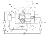
- FIG. 1 is a diagram showing the configuration of a refrigeration system 100 having a compressor 101 according to Embodiment 1.
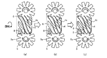
- FIG. FIG. 2 is a diagram illustrating a compression principle of a compressor 101 included in the refrigeration system 100 according to Embodiment 1;
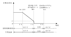
- FIG. FIG. 4 is a diagram illustrating details of stop control of compressor 101 in refrigeration system 100 according to Embodiment 1;
- FIG. 7 is a diagram for explaining the contents of stop control of compressor 101 in refrigeration system 100 according to Embodiment 2;
- FIG. 10 is a diagram for explaining details of stop control of compressor 101 in refrigeration system 100 according to Embodiment 3;
- FIG. 11 is a diagram for explaining details of stop control of a compressor 101 in a refrigeration system 100 according to Embodiment 4;
- FIG. 10 is a diagram showing the configuration of a refrigeration system 100 having a compressor 101 according to Embodiment 5;
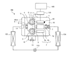
- FIG. 10 is a diagram showing the configuration of a refrigeration system 100 having a compressor 101 according to Embodiment 6;
- FIG. 1 is a diagram showing the configuration of a refrigeration system 100 having a compressor 101 according to Embodiment 1. As shown in FIG. Here, it is assumed that the compressor 101 constitutes a refrigeration cycle apparatus. Therefore, the fluid compressed by the compressor 101 becomes a refrigerant. Also, here, as an example of a refrigerating cycle device, a refrigerating device 100 for cooling objects will be described.
- the refrigeration system 100 has a refrigerant circuit configured by connecting a compressor 101, a condenser 102, a decompression device 103 and an evaporator 104 in order with refrigerant pipes.
- a refrigerant circuit circulates a refrigerant and transfers heat.
- the refrigerant circulating in the refrigerant circuit is not particularly limited here, but may be, for example, a fluorocarbon or fluoroolefin refrigerant such as HFC or HFO, a hydrocarbon refrigerant such as HC, or a natural refrigerant such as carbon dioxide or ammonia. can be done.
- the compressor 101 compresses the sucked refrigerant into a high-temperature and high-pressure state and discharges it.
- Compressor 101 of Embodiment 1 is driven by being supplied with power from a power supply source (not shown) via inverter device 105 .
- the compressor 101 in Embodiment 1 is a screw compressor. Compressor 101 will be described later.
- the condenser 102 cools and condenses the gaseous refrigerant (refrigerant gas) discharged by the compressor 101 .
- the decompression device 103 throttles the liquid refrigerant (refrigerant liquid) flowing from the condenser 102 , decompresses it, and expands it.
- the decompression device 103 has a capillary tube, an electronic expansion valve or a thermal expansion valve capable of variably adjusting the opening of a throttle.
- the evaporator 104 evaporates the refrigerant flowing out of the decompression device 103 .
- the refrigeration system 100 of Embodiment 1 includes an inverter device 105 and a control device 106 .
- the inverter device 105 and the control device 106 serve as a braking device for braking the rotation of the motor 2 in the compressor 101 .
- the control device 106 is a device that controls devices and the like of the refrigerating device 100 and controls the entire refrigerating device 100 .
- Control device 106 performs, for example, control of decompression device 103 and control of the drive frequency of inverter device 105 that drives compressor 101 .
- the controller 106 can be configured with hardware such as circuit devices that implement its functions. Moreover, it can be composed of an arithmetic unit having a microcomputer, a CPU, and the like, and software. Control of the equipment in the refrigeration system 100 is realized by the arithmetic unit executing software.
- the inverter device 105 is a device that supplies power to the motor (electric motor) 2 of the compressor 101 at a driving frequency based on an instruction from the control device 106 to drive the motor. Inverter device 105 changes the drive frequency and the rotation speed of motor 2 when, for example, the capacity of compressor 101 is changed, the drive is started (started), the compressor is stopped, or protection control is performed.
- the inverter device 105 of Embodiment 1 applies a DC voltage to the motor stator 2a to cause the motor 2 to generate torque.
- control device 106 and inverter device 105 are described as being separate from compressor 101, but this is not the only option.
- the control device 106 for the compressor 101 and the inverter device 105 may be integrated by being incorporated in the compressor 101 or the like.
- the compressor 101 will be described with reference to FIG.
- the compressor 101 of Embodiment 1 is a single screw compressor in which two gate rotors 5 are engaged with one screw rotor 4 .
- Compressor 101 includes casing 1, motor 2, screw shaft 3, screw rotor 4, gate rotor 5, and the like.
- a cylindrical casing 1 accommodates a motor 2, a screw shaft 3, a screw rotor 4, a gate rotor 5, and the like inside the cylinder.
- the motor 2 is rotationally driven to cause the compression mechanism to compress the refrigerant.
- the rotation speed of the motor 2 is changed by the inverter device 105 described above. Thereby, the capacity of the compressor 101 can be adjusted.
- the motor 2 is composed of a motor stator 2a internally fixed to the casing 1 and a motor rotor 2b arranged inside the motor stator 2a.
- the motor rotor 2 b is arranged coaxially with the screw rotor 4 and fixed to the screw shaft 3 . Both ends of the screw shaft 3 are supported by a main bearing 9 and a sub-bearing 10 .
- the motor 2 in Embodiment 1 is a PM (Permanent Magnet) motor.
- a PM motor is an electric motor having a permanent magnet in a rotor that serves as the motor rotor 2b.
- the PM motor has a small torque during driving.
- the PM motor is an energy-saving and highly efficient motor because no secondary current flows through the rotor.
- a magnetic material such as a permanent magnet has the property of being demagnetized due to a rise in temperature. For this reason, it is necessary to suppress demagnetization of the PM motor by suppressing an increase in the motor temperature and driving and braking the motor temperature to a set temperature or less.
- the compression mechanism compresses the refrigerant sucked into the compressor 101 and discharges it.
- the compression mechanism has a screw rotor 4, a gate rotor 5, and the like.
- the screw rotor 4 is columnar and rotates as the motor rotor 2b fixed to the screw shaft 3 rotates.
- the screw rotor 4 has a plurality of helical screw grooves 4a (see FIG. 2 described later) formed on its outer peripheral surface.
- a pair of gate rotors 5 are arranged on the side surface of the screw rotor 4 so as to be axially symmetrical with respect to the screw shaft 3 .
- the gate rotor 5 is disk-shaped, and has a plurality of teeth 5a (see FIG. 2, which will be described later) radially provided on the outer peripheral surface along the circumferential direction.
- the teeth 5 a of the gate rotor 5 are meshed with the screw grooves 4 a of the screw rotor 4 .
- a space surrounded by the teeth 5 a of the gate rotor 5 , the screw grooves 4 a and the inner cylindrical surface of the casing 1 serves as a compression chamber 6 .
- the strainer 7 is arranged at the refrigerant suction portion of the casing 1 to prevent dust from entering the compressor 101 .
- the casing 1 has a slide groove (not shown) inside.
- the slide valve 11 is installed movably along the slide groove.
- the slide valve 11 can adjust the timing of discharging the refrigerant from the compression chamber 6 and change the internal volume ratio.
- the internal volume ratio is the ratio of the volume of the tooth space that forms the compression chamber 6 between the volume of the tooth space when the refrigerant is sucked and the volume of the tooth space just before the refrigerant is discharged.
- the partition wall 17 partitions the inside of the casing 1 of the compressor 101 into a low-pressure portion 18 on the refrigerant suction side and a high-pressure portion 19 on the refrigerant discharge side.
- the partition 17 is integrated with the casing 1 .
- the low-pressure portion 18 where the low-pressure refrigerant is positioned becomes a low-pressure chamber that is a space of suction pressure atmosphere.
- a high-pressure portion 19 in which a high-pressure refrigerant is positioned serves as a high-pressure chamber, and has a discharge port 8 (see FIG. 2, which will be described later) that opens into the discharge flow path of the compression chamber 6 .
- high-pressure refrigerant gas and refrigerating machine oil discharged from the compression chamber 6 are present in the high-pressure section 19 of the compressor 101 .
- an oil separator 101A is provided in the high-pressure section 19 to separate the refrigerant gas discharged from the compression chamber 6 from the refrigerating machine oil and store the separated refrigerating machine oil. , bolted connections, etc.
- an oil passage (not shown) is provided for supplying refrigerating machine oil from the oil separator 101A to the compression chamber 6. As shown in FIG.
- the refrigerating machine oil is supplied to the compression chamber 6 through an oil passage and from an oil supply hole (not shown) provided in the casing 1 forming a part of the compression chamber 6 due to the pressure difference with the high pressure section 19.
- the supply destination of the refrigerating machine oil in the oil separator 101A may be a bearing chamber or the like other than the compression chamber 6 .
- the compressor 101 has a check valve 14 .
- the check valve 14 of Embodiment 1 is installed at an opening through which the compressor 101 discharges refrigerant to the outside, and prevents the refrigerant from flowing in from the discharge side outside the compressor 101 .
- the check valve 14 is positioned in the high pressure section 19 on the discharge side of the compressor 101, which is downstream in the flow of the refrigerant from the communicating portion between the communication passage section 12 and the high pressure section 19, which will be described later. Therefore, the refrigerant outside the compressor 101 does not pass through the communication channel portion 12 .
- the check valve 14 is not limited to this, and may be provided outside the compressor 101 as long as it prevents refrigerant from flowing in from the outside of the compressor 101 .
- the refrigerant gas that has passed through the compression chamber 6 and is separated by the oil separator 101A passes through the check valve 14 arranged inside the compressor 101, and then flows out of the compressor 101. is discharged to the refrigerant circuit.
- the compressor 101 of Embodiment 1 has a communication flow path portion 12 and a flow rate adjustment valve 13 that serves as a communication flow path opening/closing device.
- the communication channel portion 12 has a channel that communicates the low pressure portion 18 and the high pressure portion 19 .
- the communication channel portion 12 of Embodiment 1 is a communication channel pipe such as a copper pipe or a steel pipe.
- the communication flow path portion 12 bypasses the refrigerant and refrigerating machine oil in the high pressure portion 19 to the low pressure portion 18 .
- a communicating portion of the high-pressure portion 19 of the communicating channel portion 12 is located between the discharge port 8 and the check valve 14 in the compression mechanism.
- the communication portion of the low-pressure portion 18 of the communication passage portion 12 is connected to the casing 1 of the compressor 101 or the low-pressure side pipe connected to the compressor 101 .
- the flow rate adjustment valve 13 is a valve that adjusts the amount of refrigerant flowing through the communication flow path portion 12 by bypassing the compression mechanism having the compression chamber 6 under the opening/closing control of the control device 106, which is a braking device.
- the flow rate adjustment valve 13 is assumed to be capable of adjusting the amount of refrigerant. It is also possible to use an on-off valve or the like that blocks the passage of the .
- FIG. 2 is a diagram for explaining the compression principle of the compressor 101 included in the refrigeration system 100 according to Embodiment 1.
- FIG. 2 operation of the compressor 101 will be described.
- the screw rotor 4 rotates in the direction of the solid line arrow shown in FIG. 2 as the screw shaft 3 (see FIG. 1) rotates.
- the screw groove 4a of the screw rotor 4 is meshed with the teeth 5a of the gate rotor 5.
- the gate rotor 5 rotates in the direction of the thin white arrow shown in FIG.
- a cycle is repeated with a suction stroke, a compression stroke and a discharge stroke as one cycle.
- FIG. 2 focusing on the compression chamber 6 shaded with dots, each process will be described.
- FIG. 2(a) shows the state of the compression chamber 6 during the intake stroke.
- a screw rotor 4 is driven by the motor 2 and rotates in the direction of the solid line arrow.
- the teeth 5a of the gate rotor 5 sequentially rotate toward the discharge port 8.
- FIG. 2(b) shows the volume of the compression chamber 6 is reduced, and the refrigerant gas within the compression chamber 6 is compressed.
- the compression chamber 6 communicates with the space of the high pressure section 19 via the discharge port 8, as shown in FIG. 2(c).
- the high pressure refrigerant gas compressed in the compression chamber 6 is discharged from the discharge port 8 to the high pressure section 19 .
- the same compression is performed again on the rear surface of the screw rotor 4 .
- the compression chamber 6 composed of the casing 1, the teeth 5a of the gate rotor 5, the screw rotor 4, etc. is provided with a minute gap (not shown) for the rotation of the gate rotor 5 and the screw rotor 4.
- a minute gap in the compression chamber 6 serves as a flow path through which refrigerant gas compressed to high pressure in the compression chamber 6 and refrigerating machine oil supplied to the compression chamber 6 leak to the low pressure portion 18 .
- FIG. 3 is a diagram for explaining the details of the stop control of the compressor 101 in the refrigeration system 100 according to Embodiment 1.
- FIG. The control shown in FIG. 3 is performed each time the controller 106 stops the compressor 101 .
- control device 106 sends a stop command to the inverter device 105 in order to stop the operation of the compressor 101 (time T1). Inverter device 105 reduces the drive frequency of compressor 101 .
- the control device 106 determines that the drive frequency of the inverter device 105 has decreased to a preset drive frequency F or less, it applies an arbitrarily set DC voltage to the motor stator 2a to apply torque to the motor 2. generate. By generating torque in the motor 2, the compression mechanism and the motor rotor 2b are prevented from rotating in the reverse direction, or the reverse rotation of the compression mechanism and the motor rotor 2b is suppressed even if a force is applied to rotate the motor rotor 2b. In addition, rotation braking control can be performed. Further, when the inverter device 105 starts rotation braking control, the control device 106 performs control to open the flow rate adjustment valve 13 on the communication channel portion 12 (time T2).
- control device 106 stops applying the DC voltage by the inverter device 105 and ends the rotation braking control, it performs control to close the flow rate adjustment valve 13 on the communication channel portion 12 (time T2).
- the compressor 101 of the refrigeration system 100 of Embodiment 1 includes a PM motor as the motor 2 . Then, the control device 106 opens the flow control valve 13 arranged in the communication flow path portion 12 when the inverter device 105 starts rotation braking control. Therefore, even if the rotation of the screw rotor 4 is stopped or suppressed by the rotation braking control of the inverter device 105, the compressor 101 bypasses the communication flow path portion 12 to flow the refrigerant from the high pressure portion 19 to the low pressure portion 18. A high pressure refrigerant such as gas can be flowed. Therefore, the compressor 101 can shorten the time until the high pressure section 19 and the low pressure section 18 are equalized inside.
- the compressor 101 of Embodiment 1 can equalize the internal pressure in a short time, the reverse rotation of the screw rotor 4 can be suppressed even after the inverter device 105 cancels the rotation braking control of the motor rotor 2b. can be done. Therefore, it is possible to suppress the generation of back electromotive force in the motor 2, which is a PM motor. Therefore, the inverter device 105 can be protected. Further, since the compressor 101 of Embodiment 1 can equalize the pressure in a short period of time, it is possible to perform braking while suppressing an increase in motor temperature in the motor 2 . Therefore, the motor temperature can be kept below the set temperature, demagnetization of the permanent magnets in the PM motor can be prevented, and the compressor 101 and the refrigerating device 100 can be protected from damage and performance deterioration.
- the compressor 101 of Embodiment 1 can equalize the pressure inside the compressor 101 in a short time, the refrigerating machine oil stored in the high pressure section 19 flows out to the low pressure section 18 from the oil supply hole of the casing 1. can be suppressed.
- a highly reliable apparatus can be obtained in the motor 2, which is a PM motor.
- FIG. 4 is a diagram for explaining details of stop control of compressor 101 in refrigerating apparatus 100 according to the second embodiment.
- the control shown in FIG. 4 is performed each time the controller 106 stops the compressor 101 .
- the equipment configuration of the refrigerating apparatus 100 according to the second embodiment is the same as that of the first embodiment.
- control device 106 performs control to open the flow rate adjustment valve 13 when the rotation braking control of the motor rotor 2b by the inverter device 105 is started. Further, the control device 106 performed control to close the flow rate adjustment valve 13 when ending the rotation braking control.
- the rotation braking control performed by the control device 106 and the inverter device 105 is the same as that described in the first embodiment.
- the refrigerating apparatus 100 of the second embodiment is similar in that the control device 106 performs control to open the flow control valve 13 while the inverter device 105 is controlling the rotational braking of the motor rotor 2b.
- the flow control valve 13 is kept open for an arbitrarily set closing time ( time T4).
- the control device 106 keeps the flow control valve 13 open for the set time. Therefore, even if the pressures in the high-pressure portion 19 and the low-pressure portion 18 are not equalized when the rotation braking control of the motor rotor 2b is completed, the flow rate adjustment valve 13 is kept open, so that the pressure in the high-pressure portion is lower than that in the first embodiment. 19 and the low pressure section 18 can be shortened. Therefore, the refrigerating device 100 of the second embodiment can obtain the compressor 101 and the refrigerating device 100 that are more reliable than the refrigerating device 100 of the first embodiment.
- FIG. 5 is a diagram for explaining the contents of stop control of compressor 101 in refrigerating apparatus 100 according to the third embodiment.
- the control shown in FIG. 5 is performed each time the controller 106 stops the compressor 101 .
- the equipment configuration of the refrigerating apparatus 100 according to the third embodiment is the same as that of the first embodiment.
- control device 106 performs control to open the flow rate adjustment valve 13 when the rotation braking control of the motor rotor 2b by the inverter device 105 is started.
- the rotation braking control performed by the control device 106 and the inverter device 105 is the same as that described in the first embodiment.
- the control device 106 opens the flow rate adjustment valve 13 before starting the rotation braking control of the motor rotor 2b by the inverter device 105 to perform rotation braking control (time T1').
- the control device 106 performs control to keep the flow rate adjustment valve 13 open before starting rotation braking control of the motor rotor 2b by the inverter device 105 . Therefore, the differential pressure between the high pressure section 19 and the low pressure section 18 in the compressor 101 can be made smaller than in the first embodiment. Therefore, the DC current flowing in the rotation braking control of the motor rotor 2b by the inverter device 105 can be made smaller than the rotation braking control in the first embodiment. Therefore, it is possible to suppress the risk that an excessive current flows to the inverter device 105 during the rotation braking control and the inverter device 105 is broken.
- the refrigerating apparatus 100 of the third embodiment can shorten the pressure equalization time as compared with the first embodiment. Therefore, the refrigerating device 100 of the third embodiment can obtain the compressor 101 and the refrigerating device 100 that are more reliable than the refrigerating device 100 of the first embodiment.
- the timing for opening the flow rate regulating valve 13 before the control device 106 starts rotation braking control can be set arbitrarily. It is not limited before or after the control device 106 issues a stop command to reduce the drive frequency of the inverter device 105 .
- FIG. 6 is a diagram for explaining the details of stop control of compressor 101 in refrigeration system 100 according to the fourth embodiment.
- the control shown in FIG. 6 is performed each time the controller 106 stops the compressor 101 .
- the equipment configuration of the refrigerating apparatus 100 in the fourth embodiment is the same as the configuration in the first embodiment.
- the control device 106 performs control to open the flow rate adjustment valve 13 when the rotation braking control of the motor rotor 2b by the inverter device 105 is started. Further, the control device 106 performed control to close the flow rate adjustment valve 13 when ending the rotation braking control.
- the control device 106 keeps the flow control valve 13 open for an arbitrary set time even after the rotation braking control of the motor rotor 2b by the inverter device 105 is finished. The control remains open (time T4). Further, as in the third embodiment, the control device 106 opens the flow control valve 13 before starting rotation braking control of the motor rotor 2b by the inverter device 105, and then performs rotation braking control (time T4).
- the control device 106 performs control to keep the flow rate adjustment valve 13 open before starting rotation braking control of the motor rotor 2b by the inverter device 105 . Further, the control device 106 keeps the flow control valve 13 open for the set time even after the rotation braking control of the motor rotor 2b by the inverter device 105 is finished. Therefore, the differential pressure between the high pressure section 19 and the low pressure section 18 in the compressor 101 can be made smaller than in the first and second embodiments. Therefore, the DC current flowing in the rotation braking control of the motor rotor 2b by the inverter device 105 can be made smaller than the rotation braking control in the first embodiment.
- the timing for opening the flow control valve 13 before the control device 106 starts the rotation braking control by the inverter device 105 can be arbitrarily set. It is not limited before or after the control device 106 issues a stop command to reduce the drive frequency of the inverter device 105 .
- FIG. 7 is a diagram showing the configuration of a refrigeration system 100 having a compressor 101 according to Embodiment 5.
- the compressor 101 described in Embodiment 1 has the oil separator 101A integrated within the high pressure section 19 .
- Compressor 101 of Embodiment 5 is configured with oil separator 101A separately.
- the compressor 101 also has an oil passage pipe 15 .
- the oil passage pipe 15 serves as an oil passage through which the refrigerator oil returns from the oil separator 101A to the casing 1 .
- the oil passage pipe 15 is a pipe such as a copper pipe or a steel pipe that communicates between the oil reservoir portion of the oil separator 101A and the oil supply hole of the casing 1 of the compressor 101 .
- the oil passage pipe 15 is described as communicating with the oil supply hole of the casing 1, but it may be communicated with a bearing chamber or the like.
- An oil regulating valve 16 serving as an oil regulating device is installed in the oil passage pipe 15 .
- the oil adjustment valve 16 is a valve that opens and closes under oil amount adjustment control of the control device 106, adjusts the amount of refrigeration oil separated and stored by the oil separator 101A, and supplies the oil to the compression mechanism and the like.
- the oil adjusting device is assumed to be a valve that adjusts the amount of oil, but it may be an on-off valve.
- the oil regulating valve 16 is open, the refrigerating machine oil is supplied to the compression chamber 6 of the compression mechanism through the oil passage pipe 15 through the oil supply hole of the casing 1 due to the pressure difference with the high pressure section 19. .
- the refrigerating machine oil in the high pressure section 19 flows to the low pressure section 18 together with the refrigerant until the pressure inside the compressor 101 is equalized. Therefore, the oil adjustment valve 16 is installed in the oil passage pipe 15 , and the control device 106 performs control to close the oil adjustment valve 16 during rotation braking control by the inverter device 105 .
- the compressor 101 in the refrigerating apparatus 100 of Embodiment 5 has the oil regulating valve 16 in the oil passage pipe 15 that returns the refrigerating machine oil from the oil separator 101A.
- the control device 106 closes the oil regulating valve 16 during rotation braking control by the inverter device 105 . Therefore, the refrigerating machine oil accumulated in the oil separator 101A does not flow to the low pressure section 18. Therefore, when the compressor 101 is driven next time, it is possible to prevent damage to the compression mechanism due to insufficient injection of refrigerating machine oil, sudden suction of refrigerating machine oil, and oil compression in the compression chamber 6 . Also, the amount of refrigerant sucked from the low-pressure portion 18 into the compression chamber 6 increases, and the capacity can be enhanced.
- FIG. 8 is a diagram showing the configuration of a refrigeration system 100 having a compressor 101 according to Embodiment 6. As shown in FIG. In FIG. 8, devices denoted by the same reference numerals as those in FIG. 1 perform operations similar to those described in the first embodiment.
- Compressor 101 in refrigeration system 100 of Embodiment 6 has motor temperature detection device 20 .
- a motor temperature detection device 20 detects the motor temperature of the motor 2 .
- the motor temperature detection device 20 may have a temperature sensor for detecting temperature and send a signal of the detected temperature.
- the motor temperature detection device 20 may be a bimetal switch or the like that sends an open/close signal by closing a contact when a preset temperature is reached.
- the motor 2 which is a PM motor, has permanent magnets.
- permanent magnets have the property of demagnetizing when the temperature rises. Therefore, it is necessary to prevent the motor temperature, which rises due to the current flowing through the motor 2 during rotation braking control, from rising excessively.
- the compressor 101 of Embodiment 6 has the motor temperature detection device 20 .
- the control device 106 determines that the temperature of the motor is equal to or higher than a preset motor temperature based on the signal from the motor temperature detection device 20, the control device 106 controls the inverter device 105 so as not to perform rotational braking.
- the compressor 101 in the refrigerating apparatus 100 of Embodiment 6 has the motor temperature detection device 20, and when the control device 106 determines that the motor temperature has reached or exceeded the set motor temperature, the inverter device 105 Disabled rotation braking. Therefore, it is possible to suppress an increase in motor temperature of the motor 2, which is a PM motor, and to suppress demagnetization of the permanent magnets of the motor 2. FIG. Therefore, it is possible to prevent a decrease in the magnetic flux density of the motor 2 and a decrease in torque, efficiency, and the like. And the performance degradation of the compressor 101 and the refrigerating device 100 can be prevented.
- the braking device for braking the reverse rotation of the motor rotor 2b of the motor 2 is the inverter device 105 and the control device 106, but the present invention is not limited to this.
- the braking device may have a stopping mechanism such as a stopper that suppresses the reverse rotation of the motor rotor 2b.
- the braking device is a combination of the inverter device 105 and the control device 106, but it is not limited to this.
- a device for applying a DC voltage to the motor 2 may be provided independently of the inverter device 105, and the control device 106 may apply the DC voltage to the device to perform braking control.
- Such a compressor 101 can perform rotation braking control independently of the inverter device 105 . Therefore, the electrical connection with the inverter device 105 can be cut off during the rotation braking control, and the inverter device 105 can be protected even if counter electromotive force is generated.
- the refrigerant circulating in the refrigerant circuit of the refrigerating device 100 was not particularly limited, but it is better to use a refrigerant with a low discharge pressure.
- a refrigerant with a low discharge pressure it is possible to shorten the time when the control device 106 performs rotation braking control of the compression mechanism via the inverter device 105, and to suppress the motor temperature.
- shortage of refrigerating machine oil in the compression mechanism can be prevented.
- the compressor 101 in the first to sixth embodiments described above has been described as having the communication flow path portion 12 for communicating the low pressure portion 18 and the high pressure portion 19 outside the casing 1, but is limited to this. not something to do.
- the compressor 101 may have a bypass flow path inside the casing 1 as the communication flow path section 12 so that the low pressure section 18 and the high pressure section 19 can communicate with each other.
- the explanation was given on the assumption that there is one flow rate control valve 13 in the communication flow path portion 12, but the present invention is not limited to this.
- the communication flow path part 12 connects the high pressure part 19 and the low pressure part 18 with communication flow path pipes, the larger the pipe diameter of the communication flow path pipe, the more effective it is to shorten the time until pressure equalization. is high.
- the connection portion with the high-pressure portion 19 and the connection portion with the low-pressure portion 18 of the communication passage pipe may each have a flow control valve 13 .
- compressor 101 is a single-screw compressor in which motor 2 is the PM motor.
- the compressor 101 applied to the refrigeration system 100 is not limited to a single screw compressor.
- a twin-screw compressor having two screw rotors 4 can be used.
- a reciprocating compressor, a scroll compressor, a turbo compressor, a rotary compressor, or the like can be used.
Landscapes
- Engineering & Computer Science (AREA)
- Mechanical Engineering (AREA)
- General Engineering & Computer Science (AREA)
- Applications Or Details Of Rotary Compressors (AREA)
Abstract
Description
<冷媒回路>
図1は、実施の形態1に係る圧縮機101を有する冷凍装置100の構成を示す図である。ここでは、圧縮機101が冷凍サイクル装置を構成する機器であるものとして説明する。したがって、圧縮機101が圧縮する流体は、冷媒となる。また、ここでは、冷凍サイクル装置の一例として、物の冷却などを行う冷凍装置100について説明する。冷凍装置100は、圧縮機101、凝縮器102、減圧装置103および蒸発器104を順に冷媒配管で接続して構成された冷媒回路を有する。冷媒回路は、冷媒を循環させ、熱を搬送する。
次に、圧縮機101について、図1を参照して説明する。図1に示すように、実施の形態1の圧縮機101は、1つのスクリューロータ4に2つのゲートロータ5が係合されたタイプのシングルスクリュー圧縮機である。圧縮機101は、ケーシング1、モータ2、スクリュー軸3、スクリューロータ4およびゲートロータ5などを備える。
図4は、実施の形態2に係る冷凍装置100における圧縮機101の停止制御の内容を説明する図である。図4に示す制御は、制御装置106が圧縮機101を停止させる毎に行う。実施の形態2における冷凍装置100の機器構成については、実施の形態1の構成と同様である。
図5は、実施の形態3に係る冷凍装置100における圧縮機101の停止制御の内容を説明する図である。図5に示す制御は、制御装置106が圧縮機101を停止させる毎に行う。実施の形態3における冷凍装置100の機器構成については、実施の形態1の構成と同様である。
図6は、実施の形態4に係る冷凍装置100における圧縮機101の停止制御の内容を説明する図である。図6に示す制御は、制御装置106が圧縮機101を停止させる毎に行う。実施の形態4における冷凍装置100の機器構成については、実施の形態1の構成と同様である。
図7は、実施の形態5に係る圧縮機101を有する冷凍装置100の構成を示す図である。実施の形態1で説明した圧縮機101は、油分離器101Aを一体化して高圧部19内に有するものであった。実施の形態5の圧縮機101は、油分離器101Aが別体で構成される。そして、圧縮機101は、油流路配管15を有する。油流路配管15は、冷凍機油が油分離器101Aからケーシング1内に戻る油経路部となる。油流路配管15は、油分離器101Aにおける油溜め部となる部分と圧縮機101のケーシング1が有する給油穴とを連通する銅配管または鋼管などの配管である。ここでは、油流路配管15は、ケーシング1が有する給油穴と連通させるものとして説明するが、軸受室などと連通させるようにしてもよい。油流路配管15には、油調整装置となる油調整弁16が設置されている。油調整弁16は、制御装置106の油量調整制御により開閉し、油分離器101Aが分離して溜めた冷凍機油の油量を調整して圧縮機構などに供給する弁である。ここでは、油調整装置は、油量を調整する弁であるものとするが、開閉弁であってもよい。冷凍機油は、油調整弁16が開放されていると、高圧部19との圧力差によって、油流路配管15を通って、ケーシング1の給油穴から、圧縮機構における圧縮室6へ供給される。
図8は、実施の形態6に係る圧縮機101を有する冷凍装置100の構成を示す図である。図8において、図1と同じ符号を付している機器については、実施の形態1で説明したことと同様の動作などを行う。実施の形態6の冷凍装置100における圧縮機101は、モータ温度検出装置20を有する。モータ温度検出装置20は、モータ2のモータ温度を検出する。ここで、モータ温度検出装置20は、温度を検出する温度センサを有し、検出した温度の信号を送る構成でもよい。また、モータ温度検出装置20は、あらかじめ設定した温度になると接点が閉止するなどして開閉信号を送るバイメタルスイッチなどであってもよい。
前述した実施の形態1~実施の形態6では、モータ2のモータロータ2bの逆回転を制動する制動装置は、インバータ装置105および制御装置106であったが、これに限定するものではない。制動装置は、モータロータ2bの逆回転を抑えるストッパなどの停止機構を有するものでもよい。
Claims (17)
- 吸入した冷媒を圧縮して吐出する圧縮機構と、
回転子により前記圧縮機構を回転させるモータと、
前記圧縮機構の逆回転を制動する制動装置と
を備え、
前記モータは、前記回転子に永久磁石を有する圧縮機。 - 前記圧縮機構および前記モータを収容するケーシングと、
前記圧縮機構が圧縮した前記冷媒が通過する空間である高圧部と前記圧縮機構に吸入される前記冷媒が通過する空間である低圧部とに前記ケーシング内を分ける隔壁と、
前記圧縮機構をバイパスして前記低圧部と前記高圧部とを連通させる連通流路部と、
弁を有し、前記弁を開放して前記連通流路部に前記冷媒を通過させ、前記弁を閉止して前記連通流路部における前記冷媒の通過を遮断する連通流路開閉装置と
を備える請求項1に記載の圧縮機。 - 吐出側における外部からの前記冷媒の流入を防止する逆止弁を備え、
前記連通流路部と前記高圧部とが連通している位置は、前記冷媒の流れにおいて、前記逆止弁よりも前記圧縮機構側にある請求項2に記載の圧縮機。 - 前記制動装置は、前記連通流路開閉装置の開閉制御および前記モータに直流電圧を印可して前記モータを制動する回転制動制御を行う制御装置を有し、
前記制御装置は、前記回転制動制御をしている間、前記連通流路開閉装置を開放状態に制御する請求項2または請求項3に記載の圧縮機。 - 前記制御装置は、前記回転制動制御を終了した後の、あらかじめ定められた設定時間、前記連通流路開閉装置の開放状態を維持する請求項4に記載の圧縮機。
- 前記制御装置は、前記回転制動制御を行う前に、前記連通流路開閉装置を開放状態に制御する請求項4または請求項5に記載の圧縮機。
- 前記制動装置は、
前記モータに任意の駆動周波数の電力を供給するインバータ装置と、
前記インバータ装置の周波数制御、前記連通流路開閉装置の開閉制御および前記モータに直流電圧を印可して前記モータを制動する回転制動制御を行う制御装置とを有し、
前記制御装置は、
前記インバータ装置が前記モータに供給する前記電力の駆動周波数をあらかじめ設定した設定駆動周波数以下に周波数制御した後、前記回転制動制御を開始する請求項2~請求項6のいずれか一項に記載の圧縮機。 - 前記連通流路部は、前記ケーシングの外側から前記高圧部と前記低圧部とを連通する連通流路配管を有する請求項2~請求項7のいずれか一項に記載の圧縮機。
- 前記連通流路部は、前記ケーシングの内側に設けられる請求項2~請求項7のいずれか一項に記載の圧縮機。
- 圧縮により前記冷媒とともに吐出される冷凍機油を分離する油分離器と、
前記油分離器に溜まった前記冷凍機油を前記圧縮機構に戻す油経路部と、
前記油経路部における前記冷凍機油の油量を調整する油調整装置と
を備える請求項2~請求項9のいずれか一項に記載の圧縮機。 - 前記制動装置は、前記油調整装置の制御および前記モータに直流電圧を印可して前記モータを制動する回転制動制御を行う制御装置を有し、
前記制御装置は、前記回転制動制御をしている間、前記油調整装置に前記油経路部の通過させない油量調整制御を行う請求項10に記載の圧縮機。 - 前記モータのモータ温度を検出する温度検出装置を備える請求項1~請求項11のいずれか一項に記載の圧縮機。
- 前記制動装置は、前記モータに直流電圧を印可して前記モータを制動する回転制動制御を行う制御装置を有し、
前記制御装置は、前記モータがあらかじめ設定した設定モータ温度以上であると判定すると、前記モータの制動を解除する請求項12に記載の圧縮機。 - 前記制動装置は、前記モータにおけるモータ温度を定められた設定温度以下に抑えた制動を行う請求項1~請求項13のいずれか一項に記載の圧縮機。
- スクリュー圧縮機である請求項1~請求項14のいずれか一項に記載の圧縮機。
- 前記制動装置は、前記圧縮機構の前記逆回転を抑える停止機構である請求項1~請求項3のいずれか一項に記載の圧縮機。
- 請求項1~請求項16のいずれか一項に記載の圧縮機、凝縮器、減圧装置および蒸発器が配管接続され、冷媒の循環が行われる冷媒回路を有する冷凍サイクル装置。
Priority Applications (1)
| Application Number | Priority Date | Filing Date | Title |
|---|---|---|---|
| PCT/JP2021/019609 WO2022249239A1 (ja) | 2021-05-24 | 2021-05-24 | 圧縮機および冷凍サイクル装置 |
Applications Claiming Priority (1)
| Application Number | Priority Date | Filing Date | Title |
|---|---|---|---|
| PCT/JP2021/019609 WO2022249239A1 (ja) | 2021-05-24 | 2021-05-24 | 圧縮機および冷凍サイクル装置 |
Publications (1)
| Publication Number | Publication Date |
|---|---|
| WO2022249239A1 true WO2022249239A1 (ja) | 2022-12-01 |
Family
ID=84229686
Family Applications (1)
| Application Number | Title | Priority Date | Filing Date |
|---|---|---|---|
| PCT/JP2021/019609 Ceased WO2022249239A1 (ja) | 2021-05-24 | 2021-05-24 | 圧縮機および冷凍サイクル装置 |
Country Status (1)
| Country | Link |
|---|---|
| WO (1) | WO2022249239A1 (ja) |
Citations (3)
| Publication number | Priority date | Publication date | Assignee | Title |
|---|---|---|---|---|
| JPS51100361U (ja) * | 1975-02-12 | 1976-08-12 | ||
| JP2015105620A (ja) * | 2013-11-29 | 2015-06-08 | ダイキン工業株式会社 | 圧縮機 |
| WO2020255198A1 (ja) * | 2019-06-17 | 2020-12-24 | 三菱電機株式会社 | 冷凍装置 |
-
2021
- 2021-05-24 WO PCT/JP2021/019609 patent/WO2022249239A1/ja not_active Ceased
Patent Citations (3)
| Publication number | Priority date | Publication date | Assignee | Title |
|---|---|---|---|---|
| JPS51100361U (ja) * | 1975-02-12 | 1976-08-12 | ||
| JP2015105620A (ja) * | 2013-11-29 | 2015-06-08 | ダイキン工業株式会社 | 圧縮機 |
| WO2020255198A1 (ja) * | 2019-06-17 | 2020-12-24 | 三菱電機株式会社 | 冷凍装置 |
Similar Documents
| Publication | Publication Date | Title |
|---|---|---|
| KR100392197B1 (ko) | 공기 조화기, 실외 유닛 및 냉각 유닛 | |
| CN105579709B (zh) | 具有可变速度和容积控制的旋转压缩机 | |
| JP4516123B2 (ja) | 容量可変型ロータリ圧縮機及びその運転方法 | |
| CN100547244C (zh) | 螺杆压缩机 | |
| US5779450A (en) | Refrigerating apparatus having a fluid compressor | |
| JP5510393B2 (ja) | 複数段圧縮式冷凍サイクル装置 | |
| JP5989072B2 (ja) | 無給油式圧縮機及びその制御方法 | |
| US8966920B2 (en) | Refrigeration system | |
| WO2011040039A1 (ja) | スクリュー圧縮機 | |
| CN108626121A (zh) | 压缩机和具有它的制冷装置 | |
| EP3985327B1 (en) | Freezing apparatus | |
| WO2018037469A1 (ja) | スクリュー圧縮機及び冷凍サイクル装置 | |
| WO2022249239A1 (ja) | 圧縮機および冷凍サイクル装置 | |
| CN116710716A (zh) | 低温制冷系统和低温泵 | |
| EP3578821B1 (en) | Rotary displacement compressor | |
| JPWO2017208429A1 (ja) | 空気圧縮機の運転方法 | |
| EP3569950B1 (en) | Refrigeration cycle device | |
| WO2022249237A1 (ja) | 圧縮機および冷凍サイクル装置 | |
| WO2025074539A1 (ja) | スクリュー圧縮機および冷凍サイクル装置 | |
| JP3637368B2 (ja) | 冷凍装置 | |
| WO2016088207A1 (ja) | 冷凍サイクル回路 | |
| JP4203915B2 (ja) | 冷凍装置 | |
| KR20180024814A (ko) | 고압식 압축기 및 이를 구비한 냉동사이클 장치 | |
| WO2018003015A1 (ja) | シングルスクリュー圧縮機及び冷凍サイクル装置 | |
| JP2005344655A (ja) | 流体圧縮機の容量制御方法及び容量制御装置 |
Legal Events
| Date | Code | Title | Description |
|---|---|---|---|
| 121 | Ep: the epo has been informed by wipo that ep was designated in this application |
Ref document number: 21942897 Country of ref document: EP Kind code of ref document: A1 |
|
| WWE | Wipo information: entry into national phase |
Ref document number: 112023000180222 Country of ref document: IT |
|
| NENP | Non-entry into the national phase |
Ref country code: DE |
|
| 122 | Ep: pct application non-entry in european phase |
Ref document number: 21942897 Country of ref document: EP Kind code of ref document: A1 |
|
| NENP | Non-entry into the national phase |
Ref country code: JP |
|
| WWR | Wipo information: refused in national office |
Ref document number: 112023000180222 Country of ref document: IT |