WO2022244698A1 - Élément d'absorption des chocs et véhicule - Google Patents
Élément d'absorption des chocs et véhicule Download PDFInfo
- Publication number
- WO2022244698A1 WO2022244698A1 PCT/JP2022/020212 JP2022020212W WO2022244698A1 WO 2022244698 A1 WO2022244698 A1 WO 2022244698A1 JP 2022020212 W JP2022020212 W JP 2022020212W WO 2022244698 A1 WO2022244698 A1 WO 2022244698A1
- Authority
- WO
- WIPO (PCT)
- Prior art keywords
- absorbing member
- cell
- cell wall
- resin
- impact
- Prior art date
Links
- 210000004027 cell Anatomy 0.000 claims abstract description 97
- 210000002421 cell wall Anatomy 0.000 claims abstract description 86
- 229920005992 thermoplastic resin Polymers 0.000 claims abstract description 63
- 238000000034 method Methods 0.000 claims abstract description 50
- 230000005484 gravity Effects 0.000 claims abstract description 13
- 239000000835 fiber Substances 0.000 claims description 130
- 239000012765 fibrous filler Substances 0.000 claims description 81
- 230000035939 shock Effects 0.000 claims description 77
- 239000004645 polyester resin Substances 0.000 claims description 49
- 229920001225 polyester resin Polymers 0.000 claims description 49
- 238000002347 injection Methods 0.000 claims description 25
- 239000007924 injection Substances 0.000 claims description 25
- 239000004973 liquid crystal related substance Substances 0.000 claims description 22
- 238000004364 calculation method Methods 0.000 claims description 5
- 239000008188 pellet Substances 0.000 description 146
- 229920005989 resin Polymers 0.000 description 77
- 239000011347 resin Substances 0.000 description 77
- 238000010521 absorption reaction Methods 0.000 description 61
- 239000003365 glass fiber Substances 0.000 description 45
- 238000012360 testing method Methods 0.000 description 45
- -1 polypropylene Polymers 0.000 description 37
- 239000007788 liquid Substances 0.000 description 32
- 238000004519 manufacturing process Methods 0.000 description 27
- 229920000049 Carbon (fiber) Polymers 0.000 description 23
- 239000004917 carbon fiber Substances 0.000 description 23
- 239000000203 mixture Substances 0.000 description 23
- 239000011342 resin composition Substances 0.000 description 23
- 238000006073 displacement reaction Methods 0.000 description 22
- 101000596046 Homo sapiens Plastin-2 Proteins 0.000 description 21
- 101000762938 Homo sapiens TOX high mobility group box family member 4 Proteins 0.000 description 21
- 102100026749 TOX high mobility group box family member 4 Human genes 0.000 description 21
- 239000011521 glass Substances 0.000 description 20
- 238000000465 moulding Methods 0.000 description 19
- 230000000977 initiatory effect Effects 0.000 description 17
- 239000000463 material Substances 0.000 description 17
- 238000005470 impregnation Methods 0.000 description 16
- 238000009863 impact test Methods 0.000 description 15
- VNWKTOKETHGBQD-UHFFFAOYSA-N methane Chemical compound C VNWKTOKETHGBQD-UHFFFAOYSA-N 0.000 description 14
- 230000000052 comparative effect Effects 0.000 description 13
- 238000001746 injection moulding Methods 0.000 description 13
- 239000000155 melt Substances 0.000 description 13
- WFDIJRYMOXRFFG-UHFFFAOYSA-N Acetic anhydride Chemical compound CC(=O)OC(C)=O WFDIJRYMOXRFFG-UHFFFAOYSA-N 0.000 description 12
- 229920002292 Nylon 6 Polymers 0.000 description 12
- 239000004743 Polypropylene Substances 0.000 description 11
- 229920001155 polypropylene Polymers 0.000 description 11
- 239000000047 product Substances 0.000 description 11
- 125000003118 aryl group Chemical group 0.000 description 10
- 238000001816 cooling Methods 0.000 description 10
- 238000005259 measurement Methods 0.000 description 10
- 239000003795 chemical substances by application Substances 0.000 description 9
- 229920000728 polyester Polymers 0.000 description 9
- 238000006116 polymerization reaction Methods 0.000 description 9
- 238000005520 cutting process Methods 0.000 description 8
- 239000000945 filler Substances 0.000 description 8
- 230000001976 improved effect Effects 0.000 description 8
- 238000002156 mixing Methods 0.000 description 8
- XLYOFNOQVPJJNP-UHFFFAOYSA-N water Substances O XLYOFNOQVPJJNP-UHFFFAOYSA-N 0.000 description 8
- 125000001140 1,4-phenylene group Chemical group [H]C1=C([H])C([*:2])=C([H])C([H])=C1[*:1] 0.000 description 7
- 238000010586 diagram Methods 0.000 description 7
- 238000011156 evaluation Methods 0.000 description 7
- 229920000642 polymer Polymers 0.000 description 7
- FJKROLUGYXJWQN-UHFFFAOYSA-N 4-hydroxybenzoic acid Chemical compound OC(=O)C1=CC=C(O)C=C1 FJKROLUGYXJWQN-UHFFFAOYSA-N 0.000 description 6
- QTBSBXVTEAMEQO-UHFFFAOYSA-N Acetic acid Chemical compound CC(O)=O QTBSBXVTEAMEQO-UHFFFAOYSA-N 0.000 description 6
- IJGRMHOSHXDMSA-UHFFFAOYSA-N Atomic nitrogen Chemical compound N#N IJGRMHOSHXDMSA-UHFFFAOYSA-N 0.000 description 6
- KKEYFWRCBNTPAC-UHFFFAOYSA-N Terephthalic acid Chemical compound OC(=O)C1=CC=C(C(O)=O)C=C1 KKEYFWRCBNTPAC-UHFFFAOYSA-N 0.000 description 6
- 229910001873 dinitrogen Inorganic materials 0.000 description 6
- 239000006185 dispersion Substances 0.000 description 6
- 238000010438 heat treatment Methods 0.000 description 6
- 239000011256 inorganic filler Substances 0.000 description 6
- 229910003475 inorganic filler Inorganic materials 0.000 description 6
- QQVIHTHCMHWDBS-UHFFFAOYSA-N isophthalic acid Chemical compound OC(=O)C1=CC=CC(C(O)=O)=C1 QQVIHTHCMHWDBS-UHFFFAOYSA-N 0.000 description 6
- 239000007787 solid Substances 0.000 description 6
- 229920000106 Liquid crystal polymer Polymers 0.000 description 5
- 239000004977 Liquid-crystal polymers (LCPs) Substances 0.000 description 5
- 150000004984 aromatic diamines Chemical class 0.000 description 5
- 150000001875 compounds Chemical class 0.000 description 5
- 230000000694 effects Effects 0.000 description 5
- 239000000446 fuel Substances 0.000 description 5
- 238000004898 kneading Methods 0.000 description 5
- 239000012778 molding material Substances 0.000 description 5
- 125000001989 1,3-phenylene group Chemical group [H]C1=C([H])C([*:1])=C([H])C([*:2])=C1[H] 0.000 description 4
- VTYYLEPIZMXCLO-UHFFFAOYSA-L Calcium carbonate Chemical compound [Ca+2].[O-]C([O-])=O VTYYLEPIZMXCLO-UHFFFAOYSA-L 0.000 description 4
- 239000004677 Nylon Substances 0.000 description 4
- 239000004952 Polyamide Substances 0.000 description 4
- VYPSYNLAJGMNEJ-UHFFFAOYSA-N Silicium dioxide Chemical compound O=[Si]=O VYPSYNLAJGMNEJ-UHFFFAOYSA-N 0.000 description 4
- 229910052782 aluminium Inorganic materials 0.000 description 4
- XAGFODPZIPBFFR-UHFFFAOYSA-N aluminium Chemical compound [Al] XAGFODPZIPBFFR-UHFFFAOYSA-N 0.000 description 4
- 230000015572 biosynthetic process Effects 0.000 description 4
- 125000003178 carboxy group Chemical group [H]OC(*)=O 0.000 description 4
- 239000010410 layer Substances 0.000 description 4
- 229920001778 nylon Polymers 0.000 description 4
- 125000004430 oxygen atom Chemical group O* 0.000 description 4
- 229920002647 polyamide Polymers 0.000 description 4
- 238000004513 sizing Methods 0.000 description 4
- 239000000126 substance Substances 0.000 description 4
- MCTWTZJPVLRJOU-UHFFFAOYSA-N 1-methyl-1H-imidazole Chemical compound CN1C=CN=C1 MCTWTZJPVLRJOU-UHFFFAOYSA-N 0.000 description 3
- 229940090248 4-hydroxybenzoic acid Drugs 0.000 description 3
- PNEYBMLMFCGWSK-UHFFFAOYSA-N aluminium oxide Inorganic materials [O-2].[O-2].[O-2].[Al+3].[Al+3] PNEYBMLMFCGWSK-UHFFFAOYSA-N 0.000 description 3
- VCCBEIPGXKNHFW-UHFFFAOYSA-N biphenyl-4,4'-diol Chemical group C1=CC(O)=CC=C1C1=CC=C(O)C=C1 VCCBEIPGXKNHFW-UHFFFAOYSA-N 0.000 description 3
- 125000004432 carbon atom Chemical group C* 0.000 description 3
- BVKZGUZCCUSVTD-UHFFFAOYSA-N carbonic acid Chemical compound OC(O)=O BVKZGUZCCUSVTD-UHFFFAOYSA-N 0.000 description 3
- 238000011161 development Methods 0.000 description 3
- 238000011049 filling Methods 0.000 description 3
- 239000010445 mica Substances 0.000 description 3
- 229910052618 mica group Inorganic materials 0.000 description 3
- 239000000178 monomer Substances 0.000 description 3
- 125000004957 naphthylene group Chemical group 0.000 description 3
- 239000012766 organic filler Substances 0.000 description 3
- 125000000843 phenylene group Chemical group C1(=C(C=CC=C1)*)* 0.000 description 3
- 230000000379 polymerizing effect Effects 0.000 description 3
- 230000008569 process Effects 0.000 description 3
- 239000002994 raw material Substances 0.000 description 3
- HBMJWWWQQXIZIP-UHFFFAOYSA-N silicon carbide Chemical compound [Si+]#[C-] HBMJWWWQQXIZIP-UHFFFAOYSA-N 0.000 description 3
- 239000007790 solid phase Substances 0.000 description 3
- 239000004094 surface-active agent Substances 0.000 description 3
- 125000004959 2,6-naphthylene group Chemical group [H]C1=C([H])C2=C([H])C([*:1])=C([H])C([H])=C2C([H])=C1[*:2] 0.000 description 2
- PLIKAWJENQZMHA-UHFFFAOYSA-N 4-aminophenol Chemical compound NC1=CC=C(O)C=C1 PLIKAWJENQZMHA-UHFFFAOYSA-N 0.000 description 2
- OKTJSMMVPCPJKN-UHFFFAOYSA-N Carbon Chemical compound [C] OKTJSMMVPCPJKN-UHFFFAOYSA-N 0.000 description 2
- RYGMFSIKBFXOCR-UHFFFAOYSA-N Copper Chemical compound [Cu] RYGMFSIKBFXOCR-UHFFFAOYSA-N 0.000 description 2
- YCKRFDGAMUMZLT-UHFFFAOYSA-N Fluorine atom Chemical compound [F] YCKRFDGAMUMZLT-UHFFFAOYSA-N 0.000 description 2
- QIGBRXMKCJKVMJ-UHFFFAOYSA-N Hydroquinone Chemical compound OC1=CC=C(O)C=C1 QIGBRXMKCJKVMJ-UHFFFAOYSA-N 0.000 description 2
- AVXURJPOCDRRFD-UHFFFAOYSA-N Hydroxylamine Chemical compound ON AVXURJPOCDRRFD-UHFFFAOYSA-N 0.000 description 2
- OFOBLEOULBTSOW-UHFFFAOYSA-N Malonic acid Chemical compound OC(=O)CC(O)=O OFOBLEOULBTSOW-UHFFFAOYSA-N 0.000 description 2
- PXHVJJICTQNCMI-UHFFFAOYSA-N Nickel Chemical compound [Ni] PXHVJJICTQNCMI-UHFFFAOYSA-N 0.000 description 2
- 239000004696 Poly ether ether ketone Substances 0.000 description 2
- 239000004734 Polyphenylene sulfide Substances 0.000 description 2
- 239000000654 additive Substances 0.000 description 2
- 125000000217 alkyl group Chemical group 0.000 description 2
- 125000001118 alkylidene group Chemical group 0.000 description 2
- 125000003277 amino group Chemical group 0.000 description 2
- ADCOVFLJGNWWNZ-UHFFFAOYSA-N antimony trioxide Chemical compound O=[Sb]O[Sb]=O ADCOVFLJGNWWNZ-UHFFFAOYSA-N 0.000 description 2
- 239000007864 aqueous solution Substances 0.000 description 2
- TZCXTZWJZNENPQ-UHFFFAOYSA-L barium sulfate Chemical compound [Ba+2].[O-]S([O-])(=O)=O TZCXTZWJZNENPQ-UHFFFAOYSA-L 0.000 description 2
- 239000004305 biphenyl Substances 0.000 description 2
- 235000010290 biphenyl Nutrition 0.000 description 2
- 125000006267 biphenyl group Chemical group 0.000 description 2
- 239000006227 byproduct Substances 0.000 description 2
- 229910000019 calcium carbonate Inorganic materials 0.000 description 2
- 239000003054 catalyst Substances 0.000 description 2
- 230000008859 change Effects 0.000 description 2
- 238000006243 chemical reaction Methods 0.000 description 2
- 239000003086 colorant Substances 0.000 description 2
- 229910052802 copper Inorganic materials 0.000 description 2
- 239000010949 copper Substances 0.000 description 2
- 239000007822 coupling agent Substances 0.000 description 2
- 150000002148 esters Chemical class 0.000 description 2
- 229910052731 fluorine Inorganic materials 0.000 description 2
- 239000011737 fluorine Substances 0.000 description 2
- 229910002804 graphite Inorganic materials 0.000 description 2
- 239000010439 graphite Substances 0.000 description 2
- 125000005843 halogen group Chemical group 0.000 description 2
- 125000004435 hydrogen atom Chemical group [H]* 0.000 description 2
- 125000002887 hydroxy group Chemical group [H]O* 0.000 description 2
- 230000006872 improvement Effects 0.000 description 2
- 239000007769 metal material Substances 0.000 description 2
- 239000012299 nitrogen atmosphere Substances 0.000 description 2
- 239000002245 particle Substances 0.000 description 2
- 238000005453 pelletization Methods 0.000 description 2
- ZUOUZKKEUPVFJK-UHFFFAOYSA-N phenylbenzene Natural products C1=CC=CC=C1C1=CC=CC=C1 ZUOUZKKEUPVFJK-UHFFFAOYSA-N 0.000 description 2
- 229910052628 phlogopite Inorganic materials 0.000 description 2
- 239000004033 plastic Substances 0.000 description 2
- 229920003023 plastic Polymers 0.000 description 2
- 229920001643 poly(ether ketone) Polymers 0.000 description 2
- 229920006111 poly(hexamethylene terephthalamide) Polymers 0.000 description 2
- 229920002492 poly(sulfone) Polymers 0.000 description 2
- 239000004417 polycarbonate Substances 0.000 description 2
- 229920000515 polycarbonate Polymers 0.000 description 2
- 229920006393 polyether sulfone Polymers 0.000 description 2
- 229920002530 polyetherether ketone Polymers 0.000 description 2
- 229920001601 polyetherimide Polymers 0.000 description 2
- 229920001955 polyphenylene ether Polymers 0.000 description 2
- 229920000069 polyphenylene sulfide Polymers 0.000 description 2
- SCVFZCLFOSHCOH-UHFFFAOYSA-M potassium acetate Chemical compound [K+].CC([O-])=O SCVFZCLFOSHCOH-UHFFFAOYSA-M 0.000 description 2
- 238000010298 pulverizing process Methods 0.000 description 2
- 238000010992 reflux Methods 0.000 description 2
- 229910010271 silicon carbide Inorganic materials 0.000 description 2
- 239000000377 silicon dioxide Substances 0.000 description 2
- 238000003860 storage Methods 0.000 description 2
- 229910052882 wollastonite Inorganic materials 0.000 description 2
- 239000010456 wollastonite Substances 0.000 description 2
- CBCKQZAAMUWICA-UHFFFAOYSA-N 1,4-phenylenediamine Chemical compound NC1=CC=C(N)C=C1 CBCKQZAAMUWICA-UHFFFAOYSA-N 0.000 description 1
- 125000001637 1-naphthyl group Chemical group [H]C1=C([H])C([H])=C2C(*)=C([H])C([H])=C([H])C2=C1[H] 0.000 description 1
- HIXDQWDOVZUNNA-UHFFFAOYSA-N 2-(3,4-dimethoxyphenyl)-5-hydroxy-7-methoxychromen-4-one Chemical compound C=1C(OC)=CC(O)=C(C(C=2)=O)C=1OC=2C1=CC=C(OC)C(OC)=C1 HIXDQWDOVZUNNA-UHFFFAOYSA-N 0.000 description 1
- UOBYKYZJUGYBDK-UHFFFAOYSA-N 2-naphthoic acid Chemical compound C1=CC=CC2=CC(C(=O)O)=CC=C21 UOBYKYZJUGYBDK-UHFFFAOYSA-N 0.000 description 1
- 125000001622 2-naphthyl group Chemical group [H]C1=C([H])C([H])=C2C([H])=C(*)C([H])=C([H])C2=C1[H] 0.000 description 1
- LQZZZAFQKXTFKH-UHFFFAOYSA-N 4'-aminobiphenyl-4-ol Chemical group C1=CC(N)=CC=C1C1=CC=C(O)C=C1 LQZZZAFQKXTFKH-UHFFFAOYSA-N 0.000 description 1
- VHYFNPMBLIVWCW-UHFFFAOYSA-N 4-Dimethylaminopyridine Chemical compound CN(C)C1=CC=NC=C1 VHYFNPMBLIVWCW-UHFFFAOYSA-N 0.000 description 1
- ZCYVEMRRCGMTRW-UHFFFAOYSA-N 7553-56-2 Chemical group [I] ZCYVEMRRCGMTRW-UHFFFAOYSA-N 0.000 description 1
- GVNWZKBFMFUVNX-UHFFFAOYSA-N Adipamide Chemical compound NC(=O)CCCCC(N)=O GVNWZKBFMFUVNX-UHFFFAOYSA-N 0.000 description 1
- 229910052582 BN Inorganic materials 0.000 description 1
- ZOXJGFHDIHLPTG-UHFFFAOYSA-N Boron Chemical compound [B] ZOXJGFHDIHLPTG-UHFFFAOYSA-N 0.000 description 1
- PZNSFCLAULLKQX-UHFFFAOYSA-N Boron nitride Chemical compound N#B PZNSFCLAULLKQX-UHFFFAOYSA-N 0.000 description 1
- 229910001369 Brass Inorganic materials 0.000 description 1
- WKBOTKDWSSQWDR-UHFFFAOYSA-N Bromine atom Chemical compound [Br] WKBOTKDWSSQWDR-UHFFFAOYSA-N 0.000 description 1
- BVKZGUZCCUSVTD-UHFFFAOYSA-L Carbonate Chemical compound [O-]C([O-])=O BVKZGUZCCUSVTD-UHFFFAOYSA-L 0.000 description 1
- ZAMOUSCENKQFHK-UHFFFAOYSA-N Chlorine atom Chemical compound [Cl] ZAMOUSCENKQFHK-UHFFFAOYSA-N 0.000 description 1
- 239000004593 Epoxy Substances 0.000 description 1
- JOYRKODLDBILNP-UHFFFAOYSA-N Ethyl urethane Chemical compound CCOC(N)=O JOYRKODLDBILNP-UHFFFAOYSA-N 0.000 description 1
- JHWNWJKBPDFINM-UHFFFAOYSA-N Laurolactam Chemical compound O=C1CCCCCCCCCCCN1 JHWNWJKBPDFINM-UHFFFAOYSA-N 0.000 description 1
- 229920000571 Nylon 11 Polymers 0.000 description 1
- 229920000299 Nylon 12 Polymers 0.000 description 1
- 229920003189 Nylon 4,6 Polymers 0.000 description 1
- 229920000305 Nylon 6,10 Polymers 0.000 description 1
- 229920002302 Nylon 6,6 Polymers 0.000 description 1
- 229920000007 Nylon MXD6 Polymers 0.000 description 1
- ISWSIDIOOBJBQZ-UHFFFAOYSA-N Phenol Chemical compound OC1=CC=CC=C1 ISWSIDIOOBJBQZ-UHFFFAOYSA-N 0.000 description 1
- 239000004695 Polyether sulfone Substances 0.000 description 1
- 239000004697 Polyetherimide Substances 0.000 description 1
- 239000004721 Polyphenylene oxide Substances 0.000 description 1
- 229920000297 Rayon Polymers 0.000 description 1
- 229910052581 Si3N4 Inorganic materials 0.000 description 1
- 239000006087 Silane Coupling Agent Substances 0.000 description 1
- VMHLLURERBWHNL-UHFFFAOYSA-M Sodium acetate Chemical compound [Na+].CC([O-])=O VMHLLURERBWHNL-UHFFFAOYSA-M 0.000 description 1
- GWEVSGVZZGPLCZ-UHFFFAOYSA-N Titan oxide Chemical compound O=[Ti]=O GWEVSGVZZGPLCZ-UHFFFAOYSA-N 0.000 description 1
- RTAQQCXQSZGOHL-UHFFFAOYSA-N Titanium Chemical compound [Ti] RTAQQCXQSZGOHL-UHFFFAOYSA-N 0.000 description 1
- 229910052769 Ytterbium Inorganic materials 0.000 description 1
- 239000006096 absorbing agent Substances 0.000 description 1
- 239000002253 acid Substances 0.000 description 1
- 150000008065 acid anhydrides Chemical class 0.000 description 1
- 125000004442 acylamino group Chemical group 0.000 description 1
- 125000004423 acyloxy group Chemical group 0.000 description 1
- 239000003513 alkali Substances 0.000 description 1
- 125000004453 alkoxycarbonyl group Chemical group 0.000 description 1
- OJMOMXZKOWKUTA-UHFFFAOYSA-N aluminum;borate Chemical compound [Al+3].[O-]B([O-])[O-] OJMOMXZKOWKUTA-UHFFFAOYSA-N 0.000 description 1
- ZEASXVYVFFXULL-UHFFFAOYSA-N amezinium metilsulfate Chemical compound COS([O-])(=O)=O.COC1=CC(N)=CN=[N+]1C1=CC=CC=C1 ZEASXVYVFFXULL-UHFFFAOYSA-N 0.000 description 1
- 239000003242 anti bacterial agent Substances 0.000 description 1
- 239000003963 antioxidant agent Substances 0.000 description 1
- 239000002216 antistatic agent Substances 0.000 description 1
- 239000004760 aramid Substances 0.000 description 1
- 229920006231 aramid fiber Polymers 0.000 description 1
- 150000001491 aromatic compounds Chemical class 0.000 description 1
- 125000005161 aryl oxy carbonyl group Chemical group 0.000 description 1
- JRPBQTZRNDNNOP-UHFFFAOYSA-N barium titanate Chemical compound [Ba+2].[Ba+2].[O-][Ti]([O-])([O-])[O-] JRPBQTZRNDNNOP-UHFFFAOYSA-N 0.000 description 1
- 229910002113 barium titanate Inorganic materials 0.000 description 1
- 239000011324 bead Substances 0.000 description 1
- HFACYLZERDEVSX-UHFFFAOYSA-N benzidine Chemical group C1=CC(N)=CC=C1C1=CC=C(N)C=C1 HFACYLZERDEVSX-UHFFFAOYSA-N 0.000 description 1
- 229910052796 boron Inorganic materials 0.000 description 1
- 239000010951 brass Substances 0.000 description 1
- GDTBXPJZTBHREO-UHFFFAOYSA-N bromine Substances BrBr GDTBXPJZTBHREO-UHFFFAOYSA-N 0.000 description 1
- 229910052794 bromium Inorganic materials 0.000 description 1
- YHWCPXVTRSHPNY-UHFFFAOYSA-N butan-1-olate;titanium(4+) Chemical compound [Ti+4].CCCC[O-].CCCC[O-].CCCC[O-].CCCC[O-] YHWCPXVTRSHPNY-UHFFFAOYSA-N 0.000 description 1
- 125000002915 carbonyl group Chemical group [*:2]C([*:1])=O 0.000 description 1
- 239000000919 ceramic Substances 0.000 description 1
- 239000000460 chlorine Substances 0.000 description 1
- 229910052801 chlorine Inorganic materials 0.000 description 1
- 238000013329 compounding Methods 0.000 description 1
- 230000006835 compression Effects 0.000 description 1
- 238000007906 compression Methods 0.000 description 1
- 238000000748 compression moulding Methods 0.000 description 1
- 239000000470 constituent Substances 0.000 description 1
- 239000003484 crystal nucleating agent Substances 0.000 description 1
- 238000013016 damping Methods 0.000 description 1
- 239000002781 deodorant agent Substances 0.000 description 1
- 238000013461 design Methods 0.000 description 1
- PNOXNTGLSKTMQO-UHFFFAOYSA-L diacetyloxytin Chemical compound CC(=O)O[Sn]OC(C)=O PNOXNTGLSKTMQO-UHFFFAOYSA-L 0.000 description 1
- NJLLQSBAHIKGKF-UHFFFAOYSA-N dipotassium dioxido(oxo)titanium Chemical compound [K+].[K+].[O-][Ti]([O-])=O NJLLQSBAHIKGKF-UHFFFAOYSA-N 0.000 description 1
- YGANSGVIUGARFR-UHFFFAOYSA-N dipotassium dioxosilane oxo(oxoalumanyloxy)alumane oxygen(2-) Chemical compound [O--].[K+].[K+].O=[Si]=O.O=[Al]O[Al]=O YGANSGVIUGARFR-UHFFFAOYSA-N 0.000 description 1
- 239000000975 dye Substances 0.000 description 1
- RTZKZFJDLAIYFH-UHFFFAOYSA-N ether Substances CCOCC RTZKZFJDLAIYFH-UHFFFAOYSA-N 0.000 description 1
- 125000001495 ethyl group Chemical group [H]C([H])([H])C([H])([H])* 0.000 description 1
- 125000000219 ethylidene group Chemical group [H]C(=[*])C([H])([H])[H] 0.000 description 1
- 238000001125 extrusion Methods 0.000 description 1
- 239000003063 flame retardant Substances 0.000 description 1
- 239000006260 foam Substances 0.000 description 1
- 239000004088 foaming agent Substances 0.000 description 1
- 239000012634 fragment Substances 0.000 description 1
- 125000000524 functional group Chemical group 0.000 description 1
- 239000007789 gas Substances 0.000 description 1
- 125000005067 haloformyl group Chemical group 0.000 description 1
- 239000012760 heat stabilizer Substances 0.000 description 1
- 150000003949 imides Chemical class 0.000 description 1
- 125000001841 imino group Chemical group [H]N=* 0.000 description 1
- 239000004615 ingredient Substances 0.000 description 1
- 239000000077 insect repellent Substances 0.000 description 1
- 125000000959 isobutyl group Chemical group [H]C([H])([H])C([H])(C([H])([H])[H])C([H])([H])* 0.000 description 1
- 125000001449 isopropyl group Chemical group [H]C([H])([H])C([H])(*)C([H])([H])[H] 0.000 description 1
- 125000000654 isopropylidene group Chemical group C(C)(C)=* 0.000 description 1
- 229940046892 lead acetate Drugs 0.000 description 1
- 229920005610 lignin Polymers 0.000 description 1
- 239000000314 lubricant Substances 0.000 description 1
- 125000000040 m-tolyl group Chemical group [H]C1=C([H])C(*)=C([H])C(=C1[H])C([H])([H])[H] 0.000 description 1
- UEGPKNKPLBYCNK-UHFFFAOYSA-L magnesium acetate Chemical compound [Mg+2].CC([O-])=O.CC([O-])=O UEGPKNKPLBYCNK-UHFFFAOYSA-L 0.000 description 1
- 239000011654 magnesium acetate Substances 0.000 description 1
- 229940069446 magnesium acetate Drugs 0.000 description 1
- 235000011285 magnesium acetate Nutrition 0.000 description 1
- 238000000691 measurement method Methods 0.000 description 1
- 238000002844 melting Methods 0.000 description 1
- 230000008018 melting Effects 0.000 description 1
- 229910052751 metal Inorganic materials 0.000 description 1
- 239000002184 metal Substances 0.000 description 1
- 150000002736 metal compounds Chemical class 0.000 description 1
- 125000002496 methyl group Chemical group [H]C([H])([H])* 0.000 description 1
- 125000001570 methylene group Chemical group [H]C([H])([*:1])[*:2] 0.000 description 1
- 230000000116 mitigating effect Effects 0.000 description 1
- 238000012986 modification Methods 0.000 description 1
- 230000004048 modification Effects 0.000 description 1
- 229910052627 muscovite Inorganic materials 0.000 description 1
- 125000004108 n-butyl group Chemical group [H]C([H])([H])C([H])([H])C([H])([H])C([H])([H])* 0.000 description 1
- 125000001280 n-hexyl group Chemical group C(CCCCC)* 0.000 description 1
- 125000004123 n-propyl group Chemical group [H]C([H])([H])C([H])([H])C([H])([H])* 0.000 description 1
- RXOHFPCZGPKIRD-UHFFFAOYSA-N naphthalene-2,6-dicarboxylic acid Chemical compound C1=C(C(O)=O)C=CC2=CC(C(=O)O)=CC=C21 RXOHFPCZGPKIRD-UHFFFAOYSA-N 0.000 description 1
- 229910052759 nickel Inorganic materials 0.000 description 1
- 229920006119 nylon 10T Polymers 0.000 description 1
- 125000003261 o-tolyl group Chemical group [H]C1=C([H])C(*)=C(C([H])=C1[H])C([H])([H])[H] 0.000 description 1
- 125000001037 p-tolyl group Chemical group [H]C1=C([H])C(=C([H])C([H])=C1*)C([H])([H])[H] 0.000 description 1
- 125000001997 phenyl group Chemical group [H]C1=C([H])C([H])=C(*)C([H])=C1[H] 0.000 description 1
- 230000000704 physical effect Effects 0.000 description 1
- 239000000049 pigment Substances 0.000 description 1
- 239000000088 plastic resin Substances 0.000 description 1
- 239000004014 plasticizer Substances 0.000 description 1
- 229920006128 poly(nonamethylene terephthalamide) Polymers 0.000 description 1
- 238000006068 polycondensation reaction Methods 0.000 description 1
- 229920006149 polyester-amide block copolymer Polymers 0.000 description 1
- 229920000570 polyether Polymers 0.000 description 1
- 229920000139 polyethylene terephthalate Polymers 0.000 description 1
- 239000005020 polyethylene terephthalate Substances 0.000 description 1
- 235000011056 potassium acetate Nutrition 0.000 description 1
- 238000002360 preparation method Methods 0.000 description 1
- 238000012545 processing Methods 0.000 description 1
- 239000002964 rayon Substances 0.000 description 1
- 230000002787 reinforcement Effects 0.000 description 1
- 230000003014 reinforcing effect Effects 0.000 description 1
- 239000012783 reinforcing fiber Substances 0.000 description 1
- 230000008439 repair process Effects 0.000 description 1
- 238000005070 sampling Methods 0.000 description 1
- 125000002914 sec-butyl group Chemical group [H]C([H])([H])C([H])([H])C([H])(*)C([H])([H])[H] 0.000 description 1
- FZHAPNGMFPVSLP-UHFFFAOYSA-N silanamine Chemical compound [SiH3]N FZHAPNGMFPVSLP-UHFFFAOYSA-N 0.000 description 1
- HQVNEWCFYHHQES-UHFFFAOYSA-N silicon nitride Chemical compound N12[Si]34N5[Si]62N3[Si]51N64 HQVNEWCFYHHQES-UHFFFAOYSA-N 0.000 description 1
- 239000001632 sodium acetate Substances 0.000 description 1
- 235000017281 sodium acetate Nutrition 0.000 description 1
- 239000003381 stabilizer Substances 0.000 description 1
- 229910001220 stainless steel Inorganic materials 0.000 description 1
- 239000010935 stainless steel Substances 0.000 description 1
- 125000000472 sulfonyl group Chemical group *S(*)(=O)=O 0.000 description 1
- 229910052717 sulfur Inorganic materials 0.000 description 1
- 125000004434 sulfur atom Chemical group 0.000 description 1
- 230000008093 supporting effect Effects 0.000 description 1
- 239000002344 surface layer Substances 0.000 description 1
- 238000003786 synthesis reaction Methods 0.000 description 1
- 239000000454 talc Substances 0.000 description 1
- 229910052623 talc Inorganic materials 0.000 description 1
- 125000000999 tert-butyl group Chemical group [H]C([H])([H])C(*)(C([H])([H])[H])C([H])([H])[H] 0.000 description 1
- 239000010936 titanium Substances 0.000 description 1
- 229910052719 titanium Inorganic materials 0.000 description 1
- OGIDPMRJRNCKJF-UHFFFAOYSA-N titanium oxide Inorganic materials [Ti]=O OGIDPMRJRNCKJF-UHFFFAOYSA-N 0.000 description 1
- 239000004034 viscosity adjusting agent Substances 0.000 description 1
- 238000005303 weighing Methods 0.000 description 1
- 238000004804 winding Methods 0.000 description 1
- NAWDYIZEMPQZHO-UHFFFAOYSA-N ytterbium Chemical compound [Yb] NAWDYIZEMPQZHO-UHFFFAOYSA-N 0.000 description 1
Images


Classifications
-
- C—CHEMISTRY; METALLURGY
- C08—ORGANIC MACROMOLECULAR COMPOUNDS; THEIR PREPARATION OR CHEMICAL WORKING-UP; COMPOSITIONS BASED THEREON
- C08G—MACROMOLECULAR COMPOUNDS OBTAINED OTHERWISE THAN BY REACTIONS ONLY INVOLVING UNSATURATED CARBON-TO-CARBON BONDS
- C08G63/00—Macromolecular compounds obtained by reactions forming a carboxylic ester link in the main chain of the macromolecule
- C08G63/02—Polyesters derived from hydroxycarboxylic acids or from polycarboxylic acids and polyhydroxy compounds
- C08G63/60—Polyesters derived from hydroxycarboxylic acids or from polycarboxylic acids and polyhydroxy compounds derived from the reaction of a mixture of hydroxy carboxylic acids, polycarboxylic acids and polyhydroxy compounds
- C08G63/605—Polyesters derived from hydroxycarboxylic acids or from polycarboxylic acids and polyhydroxy compounds derived from the reaction of a mixture of hydroxy carboxylic acids, polycarboxylic acids and polyhydroxy compounds the hydroxy and carboxylic groups being bound to aromatic rings
-
- B—PERFORMING OPERATIONS; TRANSPORTING
- B29—WORKING OF PLASTICS; WORKING OF SUBSTANCES IN A PLASTIC STATE IN GENERAL
- B29C—SHAPING OR JOINING OF PLASTICS; SHAPING OF MATERIAL IN A PLASTIC STATE, NOT OTHERWISE PROVIDED FOR; AFTER-TREATMENT OF THE SHAPED PRODUCTS, e.g. REPAIRING
- B29C45/00—Injection moulding, i.e. forcing the required volume of moulding material through a nozzle into a closed mould; Apparatus therefor
-
- B—PERFORMING OPERATIONS; TRANSPORTING
- B32—LAYERED PRODUCTS
- B32B—LAYERED PRODUCTS, i.e. PRODUCTS BUILT-UP OF STRATA OF FLAT OR NON-FLAT, e.g. CELLULAR OR HONEYCOMB, FORM
- B32B27/00—Layered products comprising a layer of synthetic resin
- B32B27/18—Layered products comprising a layer of synthetic resin characterised by the use of special additives
- B32B27/20—Layered products comprising a layer of synthetic resin characterised by the use of special additives using fillers, pigments, thixotroping agents
-
- B—PERFORMING OPERATIONS; TRANSPORTING
- B32—LAYERED PRODUCTS
- B32B—LAYERED PRODUCTS, i.e. PRODUCTS BUILT-UP OF STRATA OF FLAT OR NON-FLAT, e.g. CELLULAR OR HONEYCOMB, FORM
- B32B27/00—Layered products comprising a layer of synthetic resin
- B32B27/36—Layered products comprising a layer of synthetic resin comprising polyesters
-
- B—PERFORMING OPERATIONS; TRANSPORTING
- B32—LAYERED PRODUCTS
- B32B—LAYERED PRODUCTS, i.e. PRODUCTS BUILT-UP OF STRATA OF FLAT OR NON-FLAT, e.g. CELLULAR OR HONEYCOMB, FORM
- B32B3/00—Layered products comprising a layer with external or internal discontinuities or unevennesses, or a layer of non-planar shape; Layered products comprising a layer having particular features of form
- B32B3/10—Layered products comprising a layer with external or internal discontinuities or unevennesses, or a layer of non-planar shape; Layered products comprising a layer having particular features of form characterised by a discontinuous layer, i.e. formed of separate pieces of material
- B32B3/12—Layered products comprising a layer with external or internal discontinuities or unevennesses, or a layer of non-planar shape; Layered products comprising a layer having particular features of form characterised by a discontinuous layer, i.e. formed of separate pieces of material characterised by a layer of regularly- arranged cells, e.g. a honeycomb structure
-
- B—PERFORMING OPERATIONS; TRANSPORTING
- B60—VEHICLES IN GENERAL
- B60R—VEHICLES, VEHICLE FITTINGS, OR VEHICLE PARTS, NOT OTHERWISE PROVIDED FOR
- B60R19/00—Wheel guards; Radiator guards, e.g. grilles; Obstruction removers; Fittings damping bouncing force in collisions
- B60R19/02—Bumpers, i.e. impact receiving or absorbing members for protecting vehicles or fending off blows from other vehicles or objects
- B60R19/24—Arrangements for mounting bumpers on vehicles
- B60R19/26—Arrangements for mounting bumpers on vehicles comprising yieldable mounting means
- B60R19/34—Arrangements for mounting bumpers on vehicles comprising yieldable mounting means destroyed upon impact, e.g. one-shot type
-
- B—PERFORMING OPERATIONS; TRANSPORTING
- B62—LAND VEHICLES FOR TRAVELLING OTHERWISE THAN ON RAILS
- B62D—MOTOR VEHICLES; TRAILERS
- B62D25/00—Superstructure or monocoque structure sub-units; Parts or details thereof not otherwise provided for
- B62D25/08—Front or rear portions
-
- C—CHEMISTRY; METALLURGY
- C08—ORGANIC MACROMOLECULAR COMPOUNDS; THEIR PREPARATION OR CHEMICAL WORKING-UP; COMPOSITIONS BASED THEREON
- C08K—Use of inorganic or non-macromolecular organic substances as compounding ingredients
- C08K7/00—Use of ingredients characterised by shape
- C08K7/02—Fibres or whiskers
- C08K7/04—Fibres or whiskers inorganic
- C08K7/06—Elements
-
- C—CHEMISTRY; METALLURGY
- C08—ORGANIC MACROMOLECULAR COMPOUNDS; THEIR PREPARATION OR CHEMICAL WORKING-UP; COMPOSITIONS BASED THEREON
- C08K—Use of inorganic or non-macromolecular organic substances as compounding ingredients
- C08K7/00—Use of ingredients characterised by shape
- C08K7/02—Fibres or whiskers
- C08K7/04—Fibres or whiskers inorganic
- C08K7/14—Glass
-
- C—CHEMISTRY; METALLURGY
- C08—ORGANIC MACROMOLECULAR COMPOUNDS; THEIR PREPARATION OR CHEMICAL WORKING-UP; COMPOSITIONS BASED THEREON
- C08L—COMPOSITIONS OF MACROMOLECULAR COMPOUNDS
- C08L67/00—Compositions of polyesters obtained by reactions forming a carboxylic ester link in the main chain; Compositions of derivatives of such polymers
-
- F—MECHANICAL ENGINEERING; LIGHTING; HEATING; WEAPONS; BLASTING
- F16—ENGINEERING ELEMENTS AND UNITS; GENERAL MEASURES FOR PRODUCING AND MAINTAINING EFFECTIVE FUNCTIONING OF MACHINES OR INSTALLATIONS; THERMAL INSULATION IN GENERAL
- F16F—SPRINGS; SHOCK-ABSORBERS; MEANS FOR DAMPING VIBRATION
- F16F7/00—Vibration-dampers; Shock-absorbers
- F16F7/12—Vibration-dampers; Shock-absorbers using plastic deformation of members
- F16F7/121—Vibration-dampers; Shock-absorbers using plastic deformation of members the members having a cellular, e.g. honeycomb, structure
Definitions
- the present invention relates to an impact absorbing member and a vehicle.
- This application claims priority based on Japanese Patent Application No. 2021-084347 filed on May 19, 2021 and Japanese Patent Application No. 2021-214975 filed on December 28, 2021, and the content thereof is incorporated here.
- shock-absorbing structural members for vehicles such as automobiles are required to be lightweight for saving fuel consumption and to improve collision safety.
- shock-absorbing structural members hereinafter referred to as "shock-absorbing members"
- a crash box is installed. This crash box is installed between the front side member (frame) that extends in the longitudinal direction of the vehicle and the bumper beam. It crushes and absorbs the impact energy.
- shock absorbing members were manufactured from metal materials.
- shock absorbing members were manufactured from metal materials.
- there has been a desire to reduce the weight of vehicles for the purpose of saving fuel. is being done.
- Patent Literature 1 proposes a honeycomb structure having improved strength by using a resin composition containing a thermoplastic resin and reinforcing fibers as a forming material.
- an impact absorbing member for example, in a crash box, an impact load applied in the front-rear direction of a vehicle continuously causes compression failure, thereby efficiently absorbing energy. A large impact energy is applied to this impact absorbing member in a short time at the time of a collision.
- conventional resin-made impact-absorbing members have a low impact-energy absorption capacity at the time of collision, and further improvement in impact-energy absorption performance is required.
- a shock absorbing member including a molded part containing a thermoplastic resin, wherein the molded part has a body part having a honeycomb structure filled with a plurality of cylindrical cells, and the honeycomb structure In some or all of the cylindrical cells that constitute the A shock absorbing member characterized in that it is arranged via filling cell walls.
- Procedure 1 A central axis a passing through the center of gravity of one end face and the center of gravity of the other end face of the first cylindrical cell having height H is set.
- Procedure 2) Within the range of the height H of the first cylindrical cell, set any two planes b and c perpendicular to the central axis a, and determine the distance between the two planes b and c.
- h (unit: mm; 0 ⁇ h ⁇ H).
- Step 3) Let t1 (unit: mm) be the thickness of the cell wall at the position where the cell wall between the first cylindrical cell and the adjacent second cylindrical cell intersects with the surface b.
- Step 4) Let t2 (unit: mm) be the thickness of the cell wall at the position where the cell wall between the first cylindrical cell and the adjacent second cylindrical cell intersects with the surface c. Step 5) Calculate
- thermoplastic resin is a liquid crystal polyester resin.
- a vehicle wherein the shock absorbing member according to any one of [1] to [5] is attached to at least one of a front portion, a rear portion and a side portion of the vehicle.
- an impact absorbing member that is made of a resin material, is lightweight, and has improved impact energy absorption performance.
- the impact energy absorption amount per unit weight and the impact energy absorption efficiency are improved.
- this impact absorbing member it is possible to provide a vehicle that achieves both fuel efficiency and collision safety.
- FIG. 1 is a schematic diagram showing an example of a state in which a shock absorbing member of this embodiment is attached to a vehicle; 1 is a perspective view showing one embodiment of a shock absorbing member; FIG. 5 is a height direction cross-sectional view of the shock absorbing member 500. FIG. FIG. 3B is an enlarged cross-sectional view of a portion of the cell wall 514 in FIG. 3A. 1 is a plan view (top view) showing an embodiment of a honeycomb structure that can be applied to a shock absorbing member and is composed of tubular cells having substantially equilateral triangular opening surfaces. FIG.
- FIG. 1 is a plan view (top view) showing an embodiment of a honeycomb structure that can be applied to a shock absorbing member and is composed of cylindrical cells having substantially square opening surfaces.
- FIG. 1 is a plan view (top view) showing an embodiment of a honeycomb structure that can be applied to a shock absorbing member and is composed of tubular cells having substantially regular hexagonal opening surfaces.
- FIG. It is a schematic diagram which shows an example of the manufacturing apparatus of a 1st pellet. It is a figure which shows the apparatus of a falling weight impact test. 4 is a graph showing the results of a falling weight impact test on each impact absorbing member of Example 1 and Comparative Example 1.
- FIG. FIG. 10 is a diagram showing a state of a specimen 990 placed on a test table 910 when performing a falling weight impact test in evaluation (2).
- a shock absorbing member attached to a vehicle absorbs the shock applied by the collision by collapsing the structural member itself at the time of collision. For this reason, a material having relatively low strength and rigidity is selected as the material for the shock absorbing member.
- a material having relatively low strength and rigidity is selected as the material for the shock absorbing member.
- crash boxes made of aluminum have conventionally been employed as shock absorbing members attached to vehicles. The inventors of the present invention have confirmed that the maximum load applied in the event of a collision is large for an aluminum crash box while proceeding with the development of a resin shock absorbing member. If this maximum load increases, the impact on the passenger protection space becomes stronger, other parts are damaged and the expected collision safety performance cannot be obtained, or vehicle body repair becomes difficult.
- the impact absorbing member made of resin the amount of impact energy absorption at the time of collision tends to decrease as the weight is reduced. For this reason, it is desired that the intended impact absorbing member has a high impact energy absorption amount per unit weight.
- the present inventors adopted a "resin honeycomb structure" for the main body of the shock absorbing member, and controlled the cell walls between the cells constituting this to a specific thickness. , the amount of impact energy absorbed per unit weight, and the efficiency of impact energy absorption are all improved, leading to the completion of the present invention.
- the impact-absorbing member according to one aspect of the present invention is characterized by the main body portion made of resin, and for the configuration other than the main-body portion, various known impact-absorbing members can be applied.
- the impact absorbing member of this embodiment is a structural member including a molded portion containing a thermoplastic resin.
- the molded portion in the shock absorbing member of the present embodiment includes a body portion having a honeycomb structure filled with a plurality of cylindrical cells.
- the honeycomb structure includes not only a regular hexagonal column but also a three-dimensional space-filling solid in which solid figures are arranged without gaps.
- FIG. 1 is a schematic diagram showing an example of a state in which the shock absorbing member of this embodiment is attached to a vehicle as a crash box.
- the shock absorbing member 200 of this embodiment is provided between a front side member 400 (frame) extending in the front-rear direction of the vehicle and a bumper beam 300 .
- the shock absorbing member 200 is crushed in the longitudinal direction to absorb the impact energy.
- the shock absorbing member of this embodiment includes a molded portion containing a thermoplastic resin.
- the molded portion includes a body portion having a honeycomb structure filled with a plurality of cylindrical cells. Some or all of the cylindrical cells constituting the honeycomb structure have a thickness gradient (
- FIG. 2 is a perspective view showing one embodiment of the shock absorbing member.
- the impact absorbing member 500 shown in FIG. 2 includes an injection molded portion 530 containing thermoplastic resin and fibrous filler.
- Injection molded portion 530 includes body portion 510 .
- the injection-molded portion 530 further includes a flange portion 520 integrally formed with the body portion 510 in addition to the body portion 510 .
- the body portion 510 has a honeycomb structure in which a plurality of cylindrical cells 512 are arranged without gaps. The plurality of cylindrical cells 512 are preferably formed so as to protrude from the flange portion 520 .
- the cylindrical cell 512 can be formed in a bottomed cylindrical shape with an end face on the side of the flange portion 520 closed and an end face on the side opposite to the flange portion 520 being open.
- the honeycomb structure of the main body 510 is composed of 32 cylindrical cells 512 whose open surfaces of the cylindrical cells 512 are substantially regular hexagonal when viewed from above.
- all of the cylindrical cells 512 constituting the honeycomb structure have a thickness gradient (
- FIG. 3A and 3B are diagrams for explaining [Method for calculating the thickness gradient of the cell walls] in the honeycomb structure of the main body 510.
- FIG. FIG. 3A is a height direction cross-sectional view of the shock absorbing member 500.
- FIG. 3A a cell wall 514 is formed by a first cylindrical cell 512a and an adjacent second cylindrical cell 512b.
- FIG. 3B is an enlarged cross-sectional view of a portion of the cell wall 514 in FIG. 3A.
- [Calculation method of cell wall thickness gradient] in this honeycomb structure is obtained by the following procedure.
- Procedure 1 A central axis a passing through the center of gravity of the end surface of the first cylindrical cell 512a having the height H on the side of the flange portion 520 and the center of gravity of the end surface opposite to the flange portion 520 is set.
- Procedure 2) Within the range of the height H of the first cylindrical cell 512a, set two arbitrary planes b and c perpendicular to the central axis a, and set the distance between the two planes b and c to h (Unit: mm; 0 ⁇ h ⁇ H).
- Step 3) The thickness of the cell wall 514 at the position where the surface b intersects with the cell wall 514 between the first cylindrical cell 512a and the second cylindrical cell 512b adjacent thereto is defined as t1 (unit: mm). do.
- Step 4) The thickness of the cell wall 514 at the position where the cell wall 514 between the first cylindrical cell 512a and the adjacent second cylindrical cell 512b intersects the surface c is defined as t2 (unit: mm). do.
- /h is calculated as the thickness gradient of the cell wall 514 .
- the shock absorbing member 500 which is the thickness gradient of the cell wall 514, exceeds 62.5 ⁇ 10 ⁇ 4 and is less than 250 ⁇ 10 ⁇ 4 , and is 65 ⁇ 10 ⁇ 4 or more and 200 ⁇ 10 ⁇ 4 or less is preferable, and 100 ⁇ 10 ⁇ 4 or more and 150 ⁇ 10 ⁇ 4 or less is more preferable. Since the thickness gradient of the cell wall 514 exceeds the above lower limit, the impact energy absorption performance is further enhanced. On the other hand, when the thickness gradient of the cell walls 514 is less than the upper limit, the honeycomb structure can be easily formed.
- the dimensions of the shock absorbing member 500 can be appropriately set according to the mounting object (for example, the type and size of the vehicle) and the required shock energy absorption performance.
- the height H of the first cylindrical cell 512a is 20-200 mm.
- the distance h between the two faces b and c is in the range of 0 ⁇ h ⁇ H, preferably H/2 ⁇ h ⁇ 4H/5.
- the thickness t1 of the cell wall 514 at the position where the cell wall 514 and the surface b intersect is, for example, 0.5 to 5 mm.
- the thickness t2 of the cell wall 514 at the position where the cell wall 514 and the surface c intersect is, for example, 0.5 to 5 mm.
- the thickness t1 and the thickness t2 may be t1>t2 or t1 ⁇ t2. That is, in the shock absorbing member 500, the cylindrical cells 512 may gradually thicken from the opening side toward the flange portion 520 side, or gradually thicken from the flange portion 520 side toward the opening surface side. may be However, from the viewpoint of moldability of the honeycomb structure, it is preferable that t1 ⁇ t2.
- the inner diameter of the cylindrical cell 512 at the end face (opening face) opposite to the flange portion 520 is, for example, 5 to 50 mm, preferably 5 to 20 mm.
- the inner diameter of the cell indicates the diameter of the inscribed circle of the opening surface of the cylindrical cell, and when the opening surface has a substantially regular hexagonal shape, it indicates the diameter of the substantially regular hexagonal inscribed circle.
- the thickness of the flange portion 520 is, for example, 2 to 6 mm.
- the impact absorbing member 500 can be manufactured by, for example, using a known injection molding machine to melt a resin material and inject the melted resin material into a mold having a honeycomb structure.
- /h) of the cell wall 514 can be controlled by the shape of the mold, such as the inner diameter of the cylindrical cell 512 and the height of the cylindrical cell 512, for example.
- Known injection molding machines include, for example, TR450EH3 manufactured by Sodick Co., Ltd., and hydraulic horizontal molding machine PS40E5ASE manufactured by Nissei Plastic Industry Co., Ltd. The details of the resin material of this embodiment will be described later.
- the temperature conditions for injection molding are appropriately determined according to the type of thermoplastic resin, and it is preferable to set the cylinder temperature of the injection molding machine to a temperature 10 to 80° C. higher than the flow start temperature of the thermoplastic resin to be used.
- the melt-kneading temperature of the plasticizing part is preferably 250 to 350°C, more preferably 280 to 340°C, even more preferably 290 to 330°C.
- the measuring part or plunger part preferably has a temperature of 250 to 400°C, more preferably 290 to 380°C, even more preferably 300 to 370°C.
- the temperature of the mold is preferably set in the range of room temperature (for example, 23° C.) to 220° C. from the viewpoint of the cooling rate of the thermoplastic resin and productivity.
- Other injection conditions such as screw rotation speed, back pressure, injection speed, holding pressure, holding pressure time, etc., may be appropriately adjusted.
- the gate method is not particularly limited, but from the viewpoint of suppressing the occurrence of weld lines in the injection molded portion 530, a direct gate from near the center of gravity of the bottom surface of the flange portion 520, or a film from the side surface of the flange portion 520 A gate is preferably employed.
- the injection-molded portion 530 can be molded while suppressing the occurrence of weld lines, and the impact energy absorption performance can be more easily improved.
- the gate method adopts a direct gate from near the center of gravity of the bottom surface of the flange portion 520 from the viewpoint of controllability of fiber length variation and long fiber formation in the injection molded portion 530 (that is, the flange portion It is more preferable that a gate mark is provided near the center of gravity of the bottom surface of 520).
- the shock absorbing member 500 of the embodiment described above includes a resin body portion 510 containing thermoplastic resin and fibrous filler. Therefore, according to the impact absorbing member 500, compared with the conventional impact absorbing member manufactured from a metal material, it is possible to reduce the weight and save fuel.
- the shock absorbing member 500 includes a body portion 510 having a honeycomb structure filled with a plurality of cylindrical cells 512, and the thickness gradient obtained by the above-described [method for calculating thickness gradient of cell walls]. Cylindrical cells 512 are arranged via cell walls 514 that satisfy the relationship that (
- the shock absorbing member 500 of the embodiment described above may have an outer layer surrounding the side surface of the honeycomb structure in the main body portion 510 .
- the flange portion 520 may be processed for attachment to another structural member.
- the flange portion 520 may be provided with one or more through holes at regular intervals for bolting to another structural member.
- the vicinity of the upper side surface of the main body portion 510 may also be processed for attachment to other structural members.
- the impact absorbing member according to one aspect of the present invention is not limited to the above-described embodiments, and may be other embodiments.
- all of the cylindrical cells 512 that make up the honeycomb structure have thickness gradients (
- a configuration in which they are arranged via a filling cell wall 514 may be used.
- Cylindrical cells 512 arranged via cell walls 514 that satisfy the relationship of formula (G) preferably account for 70% or more and 100% or less of all the cylindrical cells 512 constituting the honeycomb structure. is preferred, and 90% or more and 100% or less is more preferred.
- shock absorbing member 500 described above includes an injection molded portion, it is not limited to this, and may include a molded portion processed from an extruded sheet, for example. However, from the viewpoints of higher impact energy absorption performance, strength, and ease of molding, it is preferable to include an injection-molded portion.
- the honeycomb structure of the main body 510 has a substantially regular hexagonal opening surface of the cylindrical cells 512 when viewed from above, but the present invention is not limited to this. Any other shape may be used as long as the cylindrical cells can be arranged through the cell walls such that (
- 4A, 4B, and 4C are plan views (top views) showing embodiments of honeycomb structures that can be applied to shock absorbing members.
- FIG. 4A shows an embodiment in which the open surfaces of the cylindrical cells forming the honeycomb structure are substantially equilateral triangular.
- Reference numeral 514a indicates a cell wall.
- FIG. 4B shows an embodiment in which the open surfaces of the cylindrical cells forming the honeycomb structure are substantially square.
- Reference numeral 514b indicates a cell wall.
- FIG. 4C shows an embodiment in which the open surfaces of the cylindrical cells that constitute the honeycomb structure are substantially regular hexagonal.
- Reference numeral 514c indicates a cell wall.
- the radius of curvature of the vertices is preferably 0.5 mm or more.
- curvature radius of the apex means the radius of a circle when it is assumed that a minute portion including the apex is approximated to a circular arc.
- the honeycomb structure of the body portion 510 is composed of 32 cylindrical cells 512, but the present invention is not limited to this. (For example, the vehicle type, size, etc.) and the required impact energy absorption performance can be appropriately set.
- the number of cylindrical cells is, for example, in the range of 10-70.
- the inner diameter of the opening surface of the cylindrical cells can also be set as appropriate, similarly to the number of cylindrical cells.
- the impact absorbing member 500 described above has a configuration including the injection molded portion 530 containing the thermoplastic resin and the fibrous filler, but is not limited to this, and may have a configuration that does not contain the fibrous filler. However, when the molded part further contains a fibrous filler in addition to the thermoplastic resin, the impact energy absorption performance is further enhanced and the durability is improved.
- the injection molded portion 530 in the shock absorbing member 500 of this embodiment contains thermoplastic resin and fibrous filler.
- the ratio (mass ratio) between the thermoplastic resin and the fibrous filler is preferably 40 to 75 parts by mass of the thermoplastic resin and 25 to 60 parts by mass of the fibrous filler, more preferably 45 to 75 parts by mass of the thermoplastic resin and 25 to 55 parts by mass of the fibrous filler, more preferably 45 to 70 parts by mass of the thermoplastic resin and 30 to 55 parts by mass of the fibrous filler, and particularly preferably
- the thermoplastic resin is 50 to 70 parts by mass
- the fibrous filler is 30 to 50 parts by mass.
- the ratio of the fibrous filler is equal to or higher than the lower limit of the preferred range, the effect of improving the strength of the injection-molded part due to the fibrous filler can be obtained.
- the content is equal to or less than the upper limit of the preferred range, the fibrous filler is easily dispersed in the thermoplastic resin, and fiber breakage due to collision between fibers during injection molding is less likely to occur.
- the total content of the thermoplastic resin and the fibrous filler in the injection molded part 530 is preferably 80% by mass or more, more preferably 90% by mass or more, with respect to the total amount (100% by mass) of the injection molded part. , more preferably 95% by mass or more, and may be 100% by mass.
- thermoplastic resins in the present embodiment include liquid crystal polyester resins, polyamides, polypropylene, polyesters other than liquid crystal polyester resins, polysulfones, polyethersulfones, polyphenylene sulfides, polyetherketones, polyetheretherketones, polycarbonates, polyphenylene ethers, Polyetherimides are mentioned. Among these, from the viewpoint of impact energy absorption performance, it is preferable to use liquid crystal polyester resin, polyamide, and polypropylene. is particularly preferred.
- Polyamides include, for example, nylon 6 (PA6), nylon 66, nylon 11, nylon 12, nylon 46, nylon 610, polytetramethylene terephthalamide (nylon 4T), polyhexamethylene terephthalamide (nylon 6T), polymetaxylylene Adipamide (nylon MXD6), polynonamethylene terephthalamide (nylon 9T), polydecamethylene terephthalamide (nylon 10T).
- the liquid crystalline polyester resin is a polyester that exhibits liquid crystallinity in a molten state, and preferably melts at a temperature of 400° C. or less.
- a suitable liquid crystalline polyester resin contained in the molded portion of the impact absorbing member may be a liquid crystalline polyester amide, a liquid crystalline polyester ether, a liquid crystalline polyester carbonate, or a liquid crystalline polyester. It may be an imide.
- the liquid crystalline polyester resin is preferably a wholly aromatic liquid crystalline polyester using only an aromatic compound as a raw material monomer.
- liquid crystal polyester resins include aromatic hydroxycarboxylic acids, aromatic dicarboxylic acids, and at least one compound selected from the group consisting of aromatic diols, aromatic hydroxylamines and aromatic diamines.
- the aromatic hydroxycarboxylic acid, the aromatic dicarboxylic acid, the aromatic diol, the aromatic hydroxyamine and the aromatic diamine are each independently partly or wholly replaced by a polymerizable derivative thereof. good too.
- Examples of polymerizable derivatives of compounds having a carboxyl group such as aromatic hydroxycarboxylic acids and aromatic dicarboxylic acids include esters obtained by converting the carboxyl group to an alkoxycarbonyl group or an aryloxycarbonyl group, and haloformyls in place of the carboxyl group. and an acid anhydride obtained by converting a carboxyl group to an acyloxycarbonyl group.
- Examples of polymerizable derivatives of compounds having a hydroxyl group such as aromatic hydroxycarboxylic acids, aromatic diols and aromatic hydroxylamines include acylated products obtained by acylating the hydroxyl group to convert it to an acyloxyl group. be done.
- Examples of polymerizable derivatives of compounds having an amino group such as aromatic hydroxylamines and aromatic diamines include acylated products obtained by acylating the amino group to convert it to an acylamino group.
- the liquid crystal polyester resin preferably has a repeating unit represented by the following formula (1) (hereinafter sometimes referred to as “repeating unit (1)”), and the repeating unit (1) and the following formula (2)
- a repeating unit represented by (hereinafter sometimes referred to as “repeating unit (2)”) and a repeating unit represented by the following formula (3) (hereinafter sometimes referred to as “repeating unit (3)”) It is more preferable to have
- Ar 1 represents a phenylene group, a naphthylene group or a biphenylylene group.
- Ar 2 and Ar 3 each independently represent a phenylene group, a naphthylene group, a biphenylylene group or a group represented by the following formula (4).
- X and Y each independently represent an oxygen atom or an imino group (--NH--)
- the hydrogen atoms in the groups represented by Ar 1 , Ar 2 or Ar 3 each independently represent a halogen atom or an alkyl group Or it may be substituted with an aryl group.
- Ar 4 and Ar 5 each independently represent a phenylene group or a naphthylene group.
- Z represents an oxygen atom, a sulfur atom, a carbonyl group, a sulfonyl group or an alkylidene group.
- the halogen atoms include fluorine, chlorine, bromine and iodine atoms.
- alkyl group include methyl group, ethyl group, n-propyl group, isopropyl group, n-butyl group, isobutyl group, s-butyl group, t-butyl group, n-hexyl group, 2-ethylhexyl group, An n-octyl group and an n-decyl group can be mentioned, and the number of carbon atoms thereof is preferably 1-10.
- aryl group examples include phenyl group, o-tolyl group, m-tolyl group, p-tolyl group, 1-naphthyl group and 2-naphthyl group, and preferably have 6 to 20 carbon atoms.
- the number is preferably 2 or less, more preferably 1 or less, for each of the groups represented by Ar 1 , Ar 2 or Ar 3 . preferable.
- alkylidene group examples include a methylene group, an ethylidene group, an isopropylidene group, an n-butylidene group and a 2-ethylhexylidene group, and preferably have 1 to 10 carbon atoms.
- Repeating unit (1) is a repeating unit derived from a predetermined aromatic hydroxycarboxylic acid.
- the repeating unit (1) includes those in which Ar 1 is a 1,4-phenylene group (repeating units derived from p-hydroxybenzoic acid) and those in which Ar 1 is a 2,6-naphthylene group (a 6-hydroxy -Repeating units derived from 2-naphthoic acid) are preferred.
- oil means that the chemical structure of the functional group contributing to polymerization changes due to the polymerization of the raw material monomer, and no other structural change occurs.
- Repeating unit (2) is a repeating unit derived from a predetermined aromatic dicarboxylic acid.
- the repeating unit (2) includes those in which Ar 2 is a 1,4-phenylene group (repeating units derived from terephthalic acid), those in which Ar 2 is a 1,3-phenylene group (repeating units derived from isophthalic acid). ), those in which Ar 2 is a 2,6-naphthylene group (a repeating unit derived from 2,6-naphthalenedicarboxylic acid), and those in which Ar 2 is a diphenyl ether-4,4′-diyl group (diphenyl repeating units derived from ether-4,4'-dicarboxylic acid) are preferred.
- Repeating unit (3) is a repeating unit derived from a given aromatic diol, aromatic hydroxylamine or aromatic diamine.
- Repeating units (3) include those in which Ar 3 is a 1,4-phenylene group (repeating units derived from hydroquinone, p-aminophenol or p-phenylenediamine), and those in which Ar 3 is a 4,4'-biphenylylene group. (repeat units derived from 4,4'-dihydroxybiphenyl, 4-amino-4'-hydroxybiphenyl or 4,4'-diaminobiphenyl) are preferred.
- the content of the repeating unit (1) is preferably 30 mol% or more, more preferably 30 mol% or more and 80 mol% or less, still more preferably 40 mol% or more and 70 mol% or less, relative to the total amount of all repeating units. , 45 mol % or more and 65 mol % or less are particularly preferable.
- the total amount of all repeating units refers to the mass of each repeating unit constituting the liquid crystal polyester resin divided by the formula weight of each repeating unit, and the amount (mol) equivalent to the amount of each repeating unit is obtained. , means the sum of them.
- the content of the repeating unit (2) is preferably 35 mol% or less, more preferably 10 mol% or more and 35 mol% or less, even more preferably 15 mol% or more and 30 mol% or less, relative to the total amount of all repeating units. , 17.5 mol % or more and 27.5 mol % or less are particularly preferred.
- the content of the repeating unit (3) is preferably 35 mol% or less, more preferably 10 mol% or more and 35 mol% or less, still more preferably 15 mol% or more and 30 mol% or less, relative to the total amount of all repeating units. , 17.5 mol % or more and 27.5 mol % or less are particularly preferable.
- the ratio of the content of the repeating unit (2) to the content of the repeating unit (3) is expressed as [content of the repeating unit (2)]/[content of the repeating unit (3)] (mol/mol). , preferably 0.9/1 to 1/0.9, more preferably 0.95/1 to 1/0.95, even more preferably 0.98/1 to 1/0.98.
- the suitable liquid crystal polyester resin contained in the molded portion of the impact absorbing member may each independently have two or more types of repeating units (1) to (3). Further, the liquid crystalline polyester resin may have repeating units other than the repeating units (1) to (3), but the content thereof is preferably 10 mol% or less with respect to the total amount of all repeating units, 5 mol % or less is more preferable.
- Such a liquid crystalline polyester resin has a repeating unit (3) in which X and Y are each oxygen atoms, i.e., having a repeating unit derived from a predetermined aromatic diol, tends to have a low melt viscosity. Therefore, it is more preferable to have only repeating units (3) in which X and Y are each oxygen atoms.
- Such a liquid crystalline polyester resin can be produced by melt-polymerizing raw material monomers corresponding to the repeating units that constitute it, and solid-phase polymerizing the resulting polymer (hereinafter sometimes referred to as "prepolymer”). is preferred.
- prepolymer solid-phase polymerizing the resulting polymer
- melt polymerization may be carried out in the presence of a catalyst.
- this catalyst examples include metal compounds such as magnesium acetate, stannous acetate, tetrabutyl titanate, lead acetate, sodium acetate, potassium acetate, antimony trioxide, 4-(dimethylamino)pyridine, 1-methylimidazole, and the like. Nitrogen-containing heterocyclic compounds are preferably used.
- the flow initiation temperature of the liquid crystal polyester resin contained in the molded portion of the impact absorbing member is preferably 260° C. or higher, more preferably 260° C. or higher and 400° C. or lower, and even more preferably 260° C. or higher and 380° C. or lower.
- the higher the flow initiation temperature of the liquid crystalline polyester resin the more the heat resistance and strength of the liquid crystalline polyester resin tend to improve.
- the flow initiation temperature of the liquid crystalline polyester resin exceeds 400° C., the melting temperature and melt viscosity of the liquid crystalline polyester resin tend to increase. Therefore, the temperature required for molding the liquid crystal polyester resin tends to be high.
- the flow initiation temperature of the liquid crystalline polyester resin is also called flow temperature or flow temperature, and is a temperature that serves as an indication of the molecular weight of the liquid crystalline polyester resin (edited by Naoyuki Koide, "Liquid Crystal Polymer - Synthesis, Molding, Application -", CMC Co., Ltd., June 5, 1987, p.95).
- the flow initiation temperature was determined by using a capillary rheometer to melt the liquid crystalline polyester resin under a load of 9.8 MPa (100 kg/cm 2 ) at a rate of 4°C/min. It means the temperature at which the liquid crystalline polyester resin exhibits a viscosity of 4800 Pa ⁇ s (48000 poise) when extruded from.
- the liquid crystalline polyester resin may be used singly or in combination of two or more.
- two or more liquid crystalline polyester resins are used in combination, it is preferable to use resins having different flow initiation temperatures together, as described later.
- the proportion of the liquid crystal polyester resin is 10% by mass or more, preferably 25% by mass or more, relative to the total amount (100% by mass) of the thermoplastic resin. More preferably 50% by mass or more, more preferably 75% by mass or more, particularly preferably 90% by mass or more, and may be 100% by mass.
- the content of the liquid crystalline polyester resin in the molded portion of the shock absorbing member is preferably 40 to 75% by mass, more preferably 45 to 75% by mass, more preferably 45 to 70%, based on the total amount (100% by mass) of the molded portion. % by mass is more preferred, and 50 to 70% by mass is particularly preferred.
- the fibrous filler contained in the molded portion of the impact absorbing member may be a fibrous inorganic filler or a fibrous organic filler.
- fibrous inorganic fillers examples include glass fibers; carbon fibers such as PAN-based, pitch-based, rayon-based, phenol-based, and lignin-based carbon fibers; ceramic fibers such as silica fibers, alumina fibers, and silica-alumina fibers; , copper, aluminum, brass, and stainless steel fibers; silicon carbide fibers and boron fibers.
- fibrous inorganic fillers include whiskers such as potassium titanate whiskers, barium titanate whiskers, wollastonite whiskers, aluminum borate whiskers, silicon nitride whiskers, and silicon carbide whiskers.
- Fibrous organic fillers include polyester fibers, para- or meta-aramid fibers, and polyparaphenylenebenzobisoxazole (PBO) fibers.
- the fibrous filler is more preferably at least one selected from the group consisting of PAN-based or pitch-based carbon fibers and glass fibers.
- a fibrous filler coated with a metal such as nickel, copper, or ytterbium may be used.
- the carbon fiber preferably has a tensile strength of 2000 MPa or more, more preferably 3000 MPa or more, and still more preferably 4000 MPa or more.
- the carbon fiber preferably has a tensile elongation of 0.5% or more, more preferably 1.0% or more, and still more preferably 1.8% or more.
- PAN-based carbon fibers examples include “Torayca (registered trademark)” manufactured by Toray Industries, Inc., “Pyrofil (registered trademark)” manufactured by Mitsubishi Chemical Corporation, and “Tenax (registered trademark)” manufactured by Teijin Limited.
- As the pitch-based carbon fiber for example, Mitsubishi Chemical Corporation “Dialead (registered trademark)", Nippon Graphite Fiber Co., Ltd. "GRANOC (registered trademark)”, Osaka Gas Chemicals Co., Ltd. "Donna Carbo (registered trademark)”, “Kureka (registered trademark)” manufactured by Kureha Co., Ltd., and the like can be mentioned.
- Glass fibers include E-glass (i.e. alkali-free glass), S-glass or T-glass (i.e. high strength, high modulus glass), C-glass (i.e. glass for acid resistant applications), D-glass (i.e. low dielectric constant glass), ECR glass (ie, B2O3, F2-free E-glass replacement glass), AR glass (ie, glass for alkali resistant applications), and glass fibers for FRP reinforcement.
- E-glass i.e. alkali-free glass
- S-glass or T-glass i.e. high strength, high modulus glass
- C-glass i.e. glass for acid resistant applications
- D-glass i.e. low dielectric constant glass
- ECR glass ie, B2O3, F2-free E-glass replacement glass
- AR glass ie, glass for alkali resistant applications
- glass fibers for FRP reinforcement FRP reinforcement.
- E glass fiber is particularly preferable. preferable.
- the length-weighted average fiber length of the fibrous filler contained in the molded portion of the shock absorbing member is preferably 0.5 mm or longer, more preferably 1.0 mm or longer, and is preferably 1.5 mm or longer. More preferred.
- the length-weighted average fiber length of the fibrous filler is equal to or greater than the lower limit of the preferred range, the angle dependence of impact is low, and impact energy absorption is likely to be increased regardless of the impact angle. Also, when it is destroyed by collision, scattering of fragments is further suppressed.
- the length-weighted average fiber length of the fibrous filler contained in the molded portion is preferably 20 mm or less, more preferably 15 mm or less, further preferably 10 mm or less, and 8 mm or less. is particularly preferred.
- the melt fluidity of the resin composition is improved in injection molding, and the cell walls of the honeycomb structure can be made thinner and the cell inner diameter can be reduced. can be easily reduced.
- the length-weighted average fiber length of the fibrous filler contained in the molded portion is preferably 0.5 mm or more and 20 mm or less, more preferably 1.0 mm or more and 15 mm or less, and 1.5 mm or more and 15 mm or less. is more preferably 1.5 mm or more and 10 mm or less, and most preferably 1.5 mm or more and 8 mm or less.
- the length-weighted average fiber length of the fibrous filler contained in the molded part is obtained by the following procedure.
- Procedure (1) From the outermost wall of the main body, the maximum length (the length of the longest part on the projected surface of the test piece) is 20 mm or more, and the maximum vertical length (the length of the longest part in the direction of 90 degrees from the maximum length) A test piece of 20 mm or more and a test piece projected area of 200 mm 2 or more is cut out.
- Procedure (3) Disperse the resin component (fiber only) from the test piece cut out in procedure (2) in 1000 mL of an aqueous solution containing 0.05% by volume of a surfactant (Micro90 INTERNATIONAL PRODUCTS CORPORATION). to prepare a dispersion.
- VH-ZST manufactured by KEYENCE
- Procedure (5) Measure the lengths of all fibers present in one photographed image with a microscope measuring tool. A bent fiber is measured by multi-point measurement. Until the total measured number of fibers exceeds 500, the same operation is sequentially performed on 10 images taken, and the fiber length is measured.
- Procedure (6): From the fiber length of the fibers measured in procedure (5), the length-weighted average fiber length (lm) of the fibrous filler contained in the molded portion is obtained ( ⁇ ni>500). lm ( ⁇ li 2 ⁇ ni)/( ⁇ li ⁇ ni) li: fiber length of fibrous filler ni: number of fibrous fillers with fiber length li
- the content of the fibrous filler in the molded portion of the shock absorbing member is preferably 25 to 60% by mass, more preferably 30 to 55% by mass, more preferably 30 to 50%, based on the total amount (100% by mass) of the molded portion. % by mass is more preferred.
- the molded portion of the shock absorbing member may contain one or more fillers, additives, and the like, if necessary.
- fillers may be plate-shaped fillers, spherical fillers, and other granular fillers.
- Other fillers may be inorganic fillers or organic fillers.
- Plate-like inorganic fillers include talc, mica, graphite, wollastonite, glass flakes, barium sulfate, and calcium carbonate.
- the mica may be muscovite, phlogopite, fluorine phlogopite, or tetrasilicon mica.
- Particulate inorganic fillers include silica, alumina, titanium oxide, glass beads, glass balloons, boron nitride, silicon carbide, and calcium carbonate.
- Additives include weighing stabilizers, flame retardants, conductivity imparting agents, crystal nucleating agents, ultraviolet absorbers, antioxidants, damping agents, antibacterial agents, insect repellents, deodorants, anti-coloring agents, and heat stabilizers. agents, release agents, antistatic agents, plasticizers, lubricants, colorants, pigments, dyes, foaming agents, foam control agents, viscosity modifiers, and surfactants.
- a resin composition containing a thermoplastic resin and a fibrous filler is used as the resin material.
- the form of the resin composition is not particularly limited, and may be a powdery mixture of a thermoplastic resin, a fibrous filler, and optionally other components, or pellets such as resin pellets or neat pellets.
- pellets it is preferable to use pellets as the resin material from the viewpoint of controllability of fiber length variation and long fiber formation in the molded portion.
- Step of obtaining a pellet mixture In the step of obtaining the pellet mixture in this embodiment, the first pellets and the second pellets are mixed to obtain the pellet mixture.
- the first pellet comprises a resin structure in which the fibrous filler is impregnated with a first thermoplastic resin.
- the first pellets are obtained by impregnating a fibrous filler with a melt obtained by melt-kneading the first thermoplastic resin and, if necessary, other components, and pelletizing the fibrous filler.
- the filler is obtained as pellets in a state of being solidified with the first thermoplastic resin.
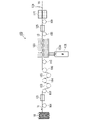
- FIG. 5 shows an embodiment of the first pellet manufacturing apparatus.
- a fiber roving 10 obtained by winding a fiber bundle 11 in which a plurality of fibrous fillers are bundled with a sizing agent is used, and the fiber roving 10 is made of the first thermoplastic resin composition.
- a case of obtaining pellets 15 will be described.
- the manufacturing apparatus 100 includes a preheating section 121, an impregnating section 123, a cooling section 125, a take-up section 127, a cutting section 129, and transport rolls 101-109.
- an extruder 120 is connected to an impregnation section 123 .
- FIG. 5 shows how the fiber bundle 11 is continuously fed out from the fiber roving 10 .
- the fiber bundle 11 fed out from the fiber roving 10 is transported in the longitudinal direction by the transport rolls 101 to 109 to produce the pellets 15 made of the first thermoplastic resin composition.
- the fineness of the fiber roving 10 used to produce the first pellets of the present embodiment is not particularly limited, but is preferably 200 g/1000 m or more, more preferably 500 g/1000 m or more, and even more preferably 800 g/1000 m or more.
- the fineness of the fiber roving 10 is equal to or higher than the lower limit of the preferable range, the fiber roving 10 can be easily handled in the first method for producing pellets.
- the fineness of the fiber roving 10 is preferably 3750 g/1000 m or less, more preferably 3200 g/1000 m or less, and even more preferably 2500 g/1000 m or less.
- the fineness of the fiber roving 10 is equal to or less than the upper limit of the preferable range, the fibers are easily dispersed in the first thermoplastic resin. Also, the fibers are easy to handle during the production of the first pellets. That is, the fineness of the fiber roving 10 is preferably 200 g/1000 m or more and 3750 g/1000 m or less, and more preferably 800 g/1000 m or more and 2500 g/1000 m or less.
- the number average fiber diameter of the fiber roving 10 is not particularly limited, it is preferably 1 to 40 ⁇ m, more preferably 3 to 35 ⁇ m.
- the fibrous filler is carbon fiber, it is preferably 1 to 15 ⁇ m, more preferably 3 to 10 ⁇ m, even more preferably 4 to 9 ⁇ m.
- the fibrous filler is glass fiber, it is preferably 5 to 35 ⁇ m, more preferably 10 to 25 ⁇ m, even more preferably 10 to 20 ⁇ m.
- the number average fiber diameter of the fiber roving 10 is obtained by observing the fibrous filler with a scanning electron microscope (1000 times) and measuring the fiber diameter of 500 randomly selected fibrous fillers. adopt.
- the fibrous filler is easily dispersed in the first pellets.
- the fibrous filler is easy to handle during the production of the first pellets.
- the content is equal to or less than the upper limit of the preferred range, the fibrous filler efficiently strengthens the molded article. Therefore, excellent impact strength can be imparted to the molded portion of the impact absorbing member.
- the fibrous filler used is treated with a sizing agent.
- Appropriately sized fibrous fillers are superior in productivity and quality stability during pellet production, and can reduce variations in physical properties in the molding section.
- the sizing agent is not particularly limited, but examples include nylon-based polymers, polyether-based polymers, epoxy-based polymers, ester-based polymers, urethane-based polymers, or mixed or modified polymers thereof.
- known coupling agents such as so-called silane coupling agents such as aminosilane and epoxysilane, and titanium coupling agents can also be used.
- the single fibers do not necessarily have to be arranged in one direction. It is preferable that the fiber bundles are arranged continuously in the fiber length direction.
- the number of single filaments of the fiber roving 10 is preferably 1000 or more and 10000 or less, more preferably 1000 or more and 8000 or less, and 1500 or more and 6000, from the viewpoint of economic efficiency and impregnation improvement. More preferred are:
- the number of single yarns of the fiber roving 10 is preferably 10000 or more and 100000 or less, more preferably 10000 or more and 50000 or less, and 10000 or more and 30000 or less. More preferred.
- the preheating unit 121 heats and dries the fiber bundle 11 fed out from the fiber roving 10 .
- the heating temperature at that time is not particularly limited, but is, for example, 50 to 250.degree. Also, the heating time in the preheating unit 121 is not particularly limited, but is, for example, 3 to 30 seconds.
- the fiber bundle 11 is impregnated with a molding material M (first thermoplastic resin, other components blended as necessary) other than the fiber bundle 11.
- first thermoplastic resin be appropriately selected in consideration of the type of the second thermoplastic resin, the melt viscosity, the flow initiation temperature, etc., as will be described later.
- the first thermoplastic resin is preferably a liquid crystal polyester resin.
- a 1st thermoplastic resin may be used individually by 1 type, and may be used in combination of 2 or more types.
- the fiber bundle 11 may be impregnated with the melt obtained by charging the molding material M from the supply port 123a and heating it in the impregnation unit 123, or the molding material M melted and kneaded by the extruder 120 may be supplied to the supply port.
- the fiber bundle 11 may be impregnated by charging from 123a.
- a resin structure 13 is obtained in which the fiber bundle 11 is impregnated and coated with the melt.
- the heating temperature in the impregnation part 123 is appropriately determined according to the type of the first thermoplastic resin, and is preferably set to a temperature 10 to 80° C. higher than the flow start temperature of the first thermoplastic resin to be used. 300-400°C.
- the impregnation part 123 100 parts by mass of the first thermoplastic resin, preferably 40 to 250 parts by mass of the fibrous filler (fiber bundle 11), more preferably fibrous 50 to 240 parts by mass of filler, more preferably 60 to 220 parts by mass of fibrous filler are impregnated. If the blending amount of the fibrous filler is equal to or higher than the lower limit of the above preferred range, the reinforcing of the molded portion with the fibers is efficiently performed. On the other hand, if it is equal to or less than the upper limit of the preferred range, the opening of the fiber bundle and the impregnation of the fiber bundle with the first thermoplastic resin are facilitated. By changing the nozzle diameter of the die head at the exit of the impregnation part 123 with respect to the diameter of the fiber bundle 11, the compounding ratio of the first thermoplastic resin and the fibrous filler in the resin structure 13 can be adjusted. .
- the resin structure 13 (the resin structure 13 in which the fiber bundle is impregnated and coated with the melt) heated by the impregnation unit 123 is cooled to, for example, 50 to 150.degree.
- the cooling time is not particularly limited, but is, for example, 3 to 30 seconds.
- the take-up unit 127 continuously takes up the resin structure 13 cooled by the cooling unit 125 and delivers it to the next cutting unit 129 .
- the cutting section 129 cuts the cooled resin structure 13 to a desired length to produce pellets 15 .
- the cutting part 129 has, for example, a rotary blade.
- Step of obtaining a resin structure While the fiber bundle 11 in which a plurality of single fibers are bundled with a sizing agent is continuously let out from the fiber roving 10 , the fiber bundle 11 is first heated and dried in the preheating section 121 . Next, while supplying the dried fiber bundle 11 to the impregnation unit 123, the molding material M melted and kneaded by the extruder 120 is introduced from the supply port 123a, and the molten molding material M is supplied to the fiber bundle 11. Impregnate. As a result, a resin structure 13 in which the fiber bundle is impregnated and coated with the melt is obtained. Thereafter, the resin structure 13 heated by the impregnating section 123 is cooled by the cooling section 125 . In the resin structure 13 obtained here, the fibers are arranged substantially parallel to the longitudinal direction of the resin structure 13 .
- the angle formed by the longitudinal direction of each structure is -5° to 5°.
- the resin structure 13 after cooling is taken up in a strand shape by the take-up part 127 and fed out to the cutting part 129 .
- a cutting section 129 cuts the strand-shaped resin structure 13 to a predetermined length in its longitudinal direction to obtain pellets 15 .
- the predetermined length of the pellets 15 referred to here is the length of the pellets 15 that is set according to the required performance of a molded article made from the pellets 15 .
- the length of the pellets 15 and the length of the fibers arranged in the pellets 15 are substantially the same. "The length of the pellet and the length of the fiber are substantially the same” means that the length-weighted average fiber length of the fibers arranged in the pellet is 95 to 95 of the length in the longitudinal direction of the pellet. 105%.
- the first pellet (pellet 15) in which the fibrous filler is impregnated with the first thermoplastic resin is produced.
- the pellets 15 are obtained by solidifying fibrous fillers with a first thermoplastic resin, and the fibrous fillers are arranged substantially parallel to the longitudinal direction of the pellets.
- the length of the fibrous filler arranged in the pellet 15 is substantially the same as the length of the pellet.
- the length of the pellets 15 produced in this embodiment is, for example, 3 to 50 mm, depending on the required performance of a molded product made from the pellets 15 .
- the fibrous filler is arranged substantially parallel to the longitudinal direction of the pellet, and the length of the fibrous filler is substantially the same as the length of the pellet.
- the remaining fibrous filler in the molded portion can be made into long fibers, which is effective in improving the heat resistance of the molded product and mitigating anisotropy.
- the arrangement direction of the fibrous filler in the pellet can be confirmed by observing the cross section of the pellet cut in the longitudinal direction with a microscope.
- the second pellets are composed of a resin structure that does not contain the fibrous filler and contains a second thermoplastic resin that has a lower flow initiation temperature than the first pellets.
- the second pellets are obtained, for example, by pelletizing a mixture of the second thermoplastic resin and, if necessary, other components by a melt extrusion molding method or a melt compression molding method.
- the second thermoplastic resin used has a flow initiation temperature lower than that of the first pellets.
- the difference in flow start temperature between the second thermoplastic resin and the first thermoplastic resin is 5°C or more, more preferably 5 to 40°C.
- the difference in flow start temperature between the second thermoplastic resin and the first pellet is 5°C or more, more preferably 5 to 40°C.
- the second thermoplastic resin has a melt viscosity of 5 to 500 Pa s (measurement conditions: nozzle hole diameter 0.5 mm, shear rate 1000 s -1 ) at the melt kneading temperature (plasticizing part) of the pellet mixture described later. things are preferred.
- the second thermoplastic resin includes liquid crystalline polyester resin, polypropylene, polyamide, polyester other than liquid crystalline polyester resin, polysulfone, polyether sulfone, polyphenylene sulfide, polyether ketone, polyether ether ketone, polycarbonate, polyphenylene ether, poly Ether imide etc. are mentioned. Among these, it is preferable to use a liquid crystal polyester resin.
- a 2nd thermoplastic resin may be used individually by 1 type, and may be used in combination of 2 or more types.
- a pellet mixture is obtained by mixing the first pellets and the second pellets described above.
- the mixing ratio (mass ratio) of the first pellet and the second pellet is preferably 40 to 70 parts by mass of the thermoplastic resin and 30 to 60 parts by mass of the fibrous filler when forming the molded part.
- the first pellet and the second pellet may be mixed.
- the mixing ratio (mass ratio) of the two is preferably 50 to 90 parts by mass of the first pellets and 10 to 50 parts by mass of the second pellets, 55 to 85 parts by mass of the first pellets, and 15 to 50 parts by mass of the second pellets. More preferably 45 parts by mass, more preferably 55 to 80 parts by mass of the first pellets and 20 to 45 parts by mass of the second pellets.
- the first pellet and the second pellet may be separately charged into a molding machine and mixed in the molding machine, or a mixture may be prepared by mixing both in advance.
- the first pellet and the second pellet may be used in such a manner that the surface of the first pellet is coated with the second pellet.
- the melt-kneading temperature (plasticized portion) of the pellets exceeds the flow start temperature of the second thermoplastic resin, and the first heat It is preferably equal to or lower than the flow initiation temperature of the plastic resin or the first pellets.
- the melt-kneading temperature (plasticizing part) is preferably 260 to 340°C, more preferably 280 to 320°C, and even more preferably 290 to 310°C.
- the measuring part or plunger part preferably has a temperature of 280 to 400°C, more preferably 290 to 380°C, even more preferably 300 to 370°C.
- a vehicle according to one aspect of the present invention includes the shock absorbing member according to one aspect of the present invention described above attached to at least one of a front portion, a rear portion, and a side portion of the vehicle.
- Examples of vehicles include bicycles, motorcycles, four-wheeled vehicles, trains, and the like.
- the impact absorbing member of the above-described embodiment since the impact absorbing member of the above-described embodiment is adopted, it is possible to reduce the weight and save fuel, and further improve the impact energy absorption performance and improve the collision safety. Both are planned.
- thermoplastic resins Liquid crystal polyester resin, polypropylene, and nylon 6 were used as thermoplastic resins.
- liquid crystal polyester resin is sometimes abbreviated as LCP
- polypropylene as PP
- Glass fiber and carbon fiber were used as the fibrous filler.
- glass fiber is sometimes abbreviated as GF
- carbon fiber is sometimes abbreviated as CF.
- Resin materials were prepared by mixing these thermoplastic resins and fibrous fillers. Specifically, neat pellets processed with liquid crystal polyester resin, resin pellets with glass fiber impregnated with liquid crystal polyester resin, resin pellets with glass fiber impregnated with polypropylene, and resin pellets with carbon fiber impregnated with nylon 6 were manufactured. .
- Neat pellet (1) (LCP1) was produced as follows. A reactor equipped with a stirrer, torque meter, nitrogen gas inlet tube, thermometer and reflux condenser was charged with p-hydroxybenzoic acid (994.5 g, 7.2 mol), 4,4'-dihydroxybiphenyl (446. 9 g, 2.4 mol), terephthalic acid (299.0 g, 1.8 mol), isophthalic acid (99.7 g, 0.6 mol), and acetic anhydride (1347.6 g, 13.2 mol); -Methylimidazole 0.9 g was added, and the inside of the reactor was sufficiently replaced with nitrogen gas.
- the liquid crystal polyester resin obtained here contains 60 mol% of the repeating unit (1) in which Ar 1 is a 1,4-phenylene group and Ar 2 is a 1,4-phenylene group, based on the total amount of all repeating units. 15 mol % of the repeating unit (2) in which Ar 2 is a 1,3-phenylene group, 5 mol % of the repeating unit (2) in which Ar 2 is a 1,3-phenylene group, and a repeating unit (3) in which Ar 3 is a 4,4'-biphenylylene group ) was 20 mol %, and its flow initiation temperature was 327°C.
- the resulting powdery liquid crystalline polyester resin was granulated with a twin-screw extruder (PMT47, manufactured by IKG) at a cylinder temperature of 320°C to obtain LCP1.
- the obtained LCP1 had a flow initiation temperature of 316°C.
- Neat pellets (2) were produced as follows. A reactor equipped with a stirrer, torque meter, nitrogen gas inlet tube, thermometer and reflux condenser was charged with p-hydroxybenzoic acid (994.5 g, 7.2 mol), 4,4'-dihydroxybiphenyl (446. 9 g, 2.4 mol), terephthalic acid (239.2 g, 1.44 mol), isophthalic acid (159.5 g, 0.96 mol) and acetic anhydride (1347.6 g, 13.2 mol) were charged and -Methylimidazole (0.9 g) was added, and the inside of the reactor was sufficiently replaced with nitrogen gas.
- the liquid crystal polyester resin obtained here contains 60 mol% of the repeating unit (1) in which Ar 1 is a 1,4-phenylene group and Ar 2 is a 1,4-phenylene group, based on the total amount of all repeating units. 12 mol % of the repeating unit (2) in which Ar 2 is a 1,3-phenylene group, 8 mol % of the repeating unit (2) in which Ar 3 is a 4,4'-biphenylylene group, and a repeating unit (3 ) was 20 mol %, and its flow initiation temperature was 291°C.
- the resulting powdery liquid crystalline polyester resin was granulated with a twin-screw extruder (PMT47, manufactured by IKG) at a cylinder temperature of 290°C to obtain LCP2.
- the obtained LCP2 had a flow initiation temperature of 284°C.
- the resin pellet 1 was manufactured as follows using a manufacturing apparatus similar to that shown in FIG.
- As the extruder 120 a GTS-40 type extruder (manufactured by Plastic Engineering Laboratory Co., Ltd.) was used.
- EBD-1500A manufactured by Imex Co., Ltd. was used as a belt-type take-up machine. The following glass fibers were used as the fibrous filler.
- Glass fiber (GF1) Glass fiber roving (E glass, number average fiber diameter 17 ⁇ m, fineness 1200 g/1000 m, manufactured by Nippon Electric Glass Co., Ltd.)
- LCP1 and LCP2 described above were used as neat pellets.
- a resin pellet 1 containing 95 parts by mass of GF1 with respect to a total of 100 parts by mass of LCP1 and LCP2 (85 parts by mass of LCP1 and 15 parts by mass of LCP2) was produced as follows.
- Step of obtaining a resin structure By operating the belt-type take-up machine (take-up unit 127), the glass fiber bundles 11 are continuously fed out from the glass fiber roving 10 of GF1 at a take-up speed of 10 m/min. The bundle 11 was dried by heating to 150°C. Next, while supplying dried glass fiber bundles 11 to a die (impregnation unit 123) attached to the tip of extruder 120, melted LCP1 and LCP2 were introduced from extruder 120 through supply port 123a.
- a die impregnation unit 123
- GF2 glass fiber roving (E glass, number average fiber diameter 10 ⁇ m, fineness 1400 g/1000 m, manufactured by Nippon Electric Glass Co., Ltd.) was used as the fibrous filler. Except that GF2 was used instead of GF1 and a die head with a nozzle diameter of 1.8 mm was used, it was produced in the same manner as resin pellet 1, and a total of 100 parts by mass of LCP1 and LCP2 (85 parts by mass of LCP1 and 15 parts by mass of LCP2 ), a resin pellet 3 having a GF2 content of 60 parts by mass was obtained.
- LCP1 and LCP2 85 parts by mass of LCP1 and 15 parts by mass of LCP2
- PA6 long fiber CF30 mass% pellet>> Resin pellets in which nylon 6 (PA6) impregnated carbon fibers were produced.
- PA6 UE nylon 1013B, manufactured by Ube Industries, Ltd.
- CF1 is used instead of GF1
- PA6 is melted at 280 ° C. in the die (impregnation part 123), impregnated into the carbon fiber bundle 11, and the nozzle diameter is 2.0 mm at the exit of the die (impregnation part 123). Except for using a die head nozzle, it was produced in the same manner as Resin Pellets 1 to obtain PA6 continuous fiber CF 30% by mass pellets with a CF1 content of 43 parts by mass for 100 parts by mass of PA6.
- Example 1 ⁇ Manufacturing of shock absorbing member> (Example 1, Comparative Example 1) Steps to obtain a pellet mixture: LCP2, which is the neat pellet prepared above, and resin pellet 1 were mixed at the ratio shown in Table 1 to obtain a resin composition (1) composed of a pellet mixture.
- Step of injection molding the resin composition The resin composition (1) was charged into the hopper of an injection molding machine TR450EH3 (manufactured by Sodick Co., Ltd.). The melt-kneaded material is melted and kneaded under the molding temperature conditions of 300°C for the plasticizing part and 360°C for the temperature of the plunger part, and is injected into a mold having a honeycomb structure under the following other molding conditions to obtain the product shown in Fig. 2 above. An injection-molded part having a main body having a honeycomb structure having the same configuration as that of 1 was molded to produce a shock absorbing member. Other molding conditions: back pressure 1 MPa, injection speed 200 mm/s, mold temperature 80°C, holding pressure 70 MPa, holding pressure time 5 seconds
- the honeycomb structure of the main body is composed of 32 cylindrical cells each having a height of 80 mm when viewed from above, an open surface having a substantially regular hexagonal shape, and a curvature radius of each vertex of 2 mm.
- the flange portion of the cell has a thickness of 3 mm, the cell inner diameter of the end surface on the flange portion side is 12.0 mm, the cell inner diameter of the end surface (opening surface) opposite to the flange portion is 13.0 mm in Example 1, and the flange portion and In Comparative Example 1, the inner diameter of the cell on the opposite end face (opening face) was 12.5 mm.
- Example 1 the thickness of the cell wall on the end face on the flange portion side of the cylindrical cell was 2.0 mm, and the thickness of the cell wall on the end face (opening face) opposite to the flange portion was 1.0 mm (the flange portion The cell wall average thickness from the side end face to the end face (opening face) on the opposite side of the flange portion is 1.5 mm), and the cell wall thickness of the end face (opening face) on the opposite side to the flange portion is Comparative Example 1. was 1.5 mm (average cell wall thickness from the end face on the flange portion side to the end face (opening face) on the opposite side to the flange portion was 1.75 mm).
- Example 2 Comparative Example 2 Steps to obtain a pellet mixture: LCP2, which is the neat pellet prepared above, and resin pellet 3 were mixed at the ratio shown in Table 1 to obtain a resin composition (3) composed of a pellet mixture.
- Step of injection molding the resin composition In Example 2, injection was carried out in the same manner as in Example 1 above, and in Comparative Example 2, in the same manner as in Comparative Example 1 above, except that the resin composition (3) was used instead of the resin composition (1). A molded portion was molded to manufacture an impact absorbing member.
- Example 3 Comparative Example 3 Steps to obtain a pellet mixture: LCP2, which is the neat pellet prepared above, and resin pellet 4 were mixed at the ratio shown in Table 1 to obtain a resin composition (4) composed of a pellet mixture.
- Step of injection molding the resin composition Injection molding was performed in the same manner as in Example 1 above in Example 3, and in Comparative Example 3 in the same manner as in Comparative Example 1 above, except that the resin composition (4) was used instead of the resin composition (1). A part was molded to manufacture a shock absorbing member.
- Example 4 An injection-molded portion was molded in the same manner as in Example 1 to manufacture a shock absorbing member.
- Example 5 An injection-molded part was formed in the same manner as in Example 1 above, except that a resin composition (2) made of a pellet mixture obtained by mixing LCP 2, which is a neat pellet, and resin pellet 2 at the ratio shown in Table 1 was used. It was molded to produce an impact absorbing member.
- Example 6 An injection-molded portion was formed in the same manner as in Example 3 to produce a shock absorbing member.
- Example 7 A resin composition (5) made of a pellet mixture obtained by mixing LCP1, which is a neat pellet, and resin pellet 5 in the ratio shown in Table 1, and according to this, the temperature of the plasticizing part was set to 330 ° C., and the plan A shock absorbing member was manufactured by molding an injection-molded portion in the same manner as in Example 1 above, except that the temperature of the jar portion was changed to 340°C.
- Example 8 An impact absorbing member was produced by molding an injection-molded part in the same manner as in Example 1 above, except that LCP staple fiber GF 35% by mass pellets were used and the temperature of the plasticized part was changed to 350 ° C. accordingly. .
- Example 9 The above example except that PP long fiber GF40 mass% pellets were used, and the temperature of the plasticizing part was changed to 250 ° C., the temperature of the plunger part was changed to 250 ° C., and the mold temperature was changed to 50 ° C. An injection-molded portion was formed in the same manner as in 1 to produce a shock absorbing member.
- Example 10 The above example except that PA6 long fiber CF 30 mass% pellets were used, and the temperature of the plasticizing part was changed to 270 ° C., the temperature of the plunger part was changed to 270 ° C., and the mold temperature was changed to 70 ° C. An injection-molded portion was formed in the same manner as in 1 to produce a shock absorbing member.
- Example 11 An injection-molded portion was molded in the same manner as in Example 7 to produce a shock absorbing member.
- Example 12 An injection-molded portion was formed in the same manner as in Example 9 to produce a shock absorbing member.
- Example 13 An injection-molded portion was molded in the same manner as in Example 10 to produce a shock absorbing member.
- Example 14 Steps to obtain a pellet mixture: LCP2, which is the neat pellet prepared above, and resin pellet 6 were mixed at the ratio shown in Table 1 to obtain a resin composition (6) composed of a pellet mixture.
- Step of injection molding the resin composition An injection-molded part was formed in the same manner as in Example 1 above, except that the resin composition (6) was used instead of the resin composition (1), and the temperature of the plasticized part was changed to 350°C accordingly. Then, an impact absorbing member was manufactured.
- Example 15 An injection-molded portion was formed in the same manner as in Example 14, except that a mold having the following shape (honeycomb structure) was used to produce a shock absorbing member.
- the honeycomb structure of the main body is composed of 32 cylindrical cells each having a height of 80 mm in a top view, an open surface having a substantially regular hexagonal shape, and a radius of curvature of each vertex of 2 mm.
- the thickness of the flange portion was 3 mm
- the cell inner diameter of the end face on the flange portion side was 12.3 mm
- the cell inner diameter of the end face (opening face) on the opposite side to the flange portion was 13.3 mm.
- the thickness of the cell wall on the end face on the flange portion side of the cylindrical cell is 1.7 mm
- the thickness of the cell wall on the end face (opening face) opposite to the flange portion is 0.7 mm (from the end face on the flange portion side).
- the average cell wall thickness to the end face (opening face) on the opposite side to the flange portion was 1.2 mm).
- Example 16 An injection-molded portion was formed in the same manner as in Example 14 above, except that a mold having a honeycomb structure having the following shape was used to produce a shock absorbing member.
- the honeycomb structure of the main body is composed of 56 cylindrical cells each having a height of 80 mm when viewed from the top, an open surface having a substantially regular hexagonal shape, and a radius of curvature of each vertex of 2 mm.
- the thickness of the flange portion was 3 mm
- the cell inner diameter of the end face on the flange portion side was 7.6 mm
- the cell inner diameter of the end face (opening face) on the opposite side to the flange portion was 8.6 mm.
- the thickness of the cell wall on the end face on the flange portion side of the cylindrical cell is 1.7 mm
- the thickness of the cell wall on the end face (opening face) opposite to the flange portion is 0.7 mm (from the end face on the flange portion side).
- the average cell wall thickness to the end face (opening face) on the opposite side to the flange portion was 1.2 mm).
- Procedure 3 The thickness of the cell wall at the position (opening surface side) where the cell wall between the first cylindrical cell and the adjacent second cylindrical cell intersects with the surface b is set to t1 mm. .
- Step 4) The thickness of the cell wall at the position (flange portion side) where the cell wall between the first cylindrical cell and the adjacent second cylindrical cell intersects with the surface c is set to t2 mm. .
- Step 5)
- /h, h 70 was calculated as the thickness gradient of the cell wall.
- Procedure (2) The test pieces were heated in a muffle furnace at 600°C for 4 hours for glass fibers and at 500°C for 3 hours for carbon fibers to remove the resin content.
- Procedure (3) Disperse the resin component (fiber only) from the test piece cut out in procedure (2) in 1000 mL of an aqueous solution containing 0.05% by volume of a surfactant (Micro90 INTERNATIONAL PRODUCTS CORPORATION). to prepare a dispersion.
- Procedure (4) 100 mL was taken out from the dispersion and diluted 10 times with pure water.
- Procedure (5) The lengths of all fibers present in one photographed image were measured with a microscope measuring tool. The bent fibers were measured by multi-point measurement. Until the total number of measured fibers exceeded 500, the same operation was sequentially performed with 10 images taken, and the fiber length was measured.
- Table 1 shows the resin materials and molding conditions used to manufacture the shock absorbing members of each example.
- the effective volume of the injection-molded part exists within the effective displacement region of the weight during the falling weight impact test (the distance from the initial position of the weight (the upper surface of the test piece 990 placed on the test table 910) to the weight stopper). indicates the volume of the injection-molded part.
- FIG. 6 is a diagram showing an apparatus for a falling weight impact test.
- the apparatus 900 includes a test table 910, a load cell 920 supporting the test table 910 below, displacement gauges 930a and 930b spaced apart on both left and right sides of the load cell 920, and the test table 910. and a weight stopper 950 for stopping the falling weight 940.
- a test piece 990 is placed on a test stand 910 .
- the dropped weight 940 is in contact with the upper surface of the specimen 990 .
- Drop weight impact test method A test piece 990 was used as the shock absorbing member of each example. Using the device 900 shown in FIG. 6, a weight body 940 was allowed to fall freely to give an impact to a test body 990 on a load meter 920 . At that time, the load [kN] applied to the test piece 990 and the displacement [mm] of the upper surface of the test piece 990 were measured.
- Used equipment As the load cell 920, a model "CLP-30BS” manufactured by a device manufacturer "TOKYO SOKKI KENKYUJO CO. LTD” was used.
- model "LK-G505 (north side: No. 1271178, south side: No. 1261015)” and equipment manufacturer “KEYENCE CORPORATION” were used.
- a model "DIS-5200A” manufactured by “KYOWA ELECTRONIC INSTRUMENTS CO. LTD” was used.
- As the high-speed camera model “MEMRECAM GX-1” and equipment manufacturer "Nac Image Technology Co., Ltd.” were used.
- the analog filters of the load meter 920 and the displacement meters 930a and 930b were set to 10 kHz.
- the sampling frequency of the recording device was 50 kHz, and the analog filter was 10 kHz.
- the photographing was performed at 5000 fps using a high-speed camera.
- FIG. 7 is a graph showing the results of a falling weight impact test (inclination angle of test table 910: 0°, effective displacement: 55 mm) for each impact absorbing member of Example 1 and Comparative Example 1.
- FIG. The vertical axis represents the load (kN) applied to the specimen 990 on the left side, and the absorbed energy (kJ) on the right side.
- the horizontal axis represents the displacement [mm] of the upper surface of the test piece 990 (the lower surface of the weight 940 in contact with the upper surface of the test piece 990). Let the initial position of the top surface of the test piece 990 be 0 mm. Based on the results of the graph shown in FIG.
- Impact energy absorption amount per unit weight was calculated as follows. A higher value means higher impact energy absorption performance.
- Impact energy absorption per unit weight (J/g) Amount of impact energy absorbed up to effective displacement / Mass of forming material destroyed up to effective displacement
- Impact energy absorption efficiency actual impact energy absorption (kJ) / (maximum load (kN) x effective displacement (m))
- /h) satisfies the relationship of formula (G) both of which can be confirmed to have high impact energy absorption performance.
- the impact-absorbing members of Examples 14 to 16 had large impact energy absorption values per unit weight.
- the impact energy absorption amount per unit weight increased in the order of Example 14, Example 15, and Example 16. From the comparison between Example 14 and Example 15, it can be considered that this is due to the effect of thinning the cell walls.
- the effect of reducing the inner diameter of the cell can be considered.
- FIG. 8 is a diagram showing the state of a specimen 990 placed on a test table 910 when performing the falling weight impact test in evaluation (2). In FIG. 8, the specimen 990 is placed at an inclination angle of 15° with respect to the test table 910 .
- Angular dependency Impact energy absorption per unit weight at an inclination angle of 15°/Impact energy absorption per unit weight at an inclination angle of 0° The higher this value, the lower the angle dependency of the impact, and the impact energy due to the impact angle. It means that the impact on absorption performance is low.
- the amount of impact energy absorbed per unit weight at an inclination angle of 0° was determined by a falling weight impact test ( It was obtained by setting the test table 910 at an inclination angle of 0° and an effective displacement of 55 mm.
- the effective volume of the injection-molded part exists within the effective displacement region of the weight during the falling weight impact test (the distance from the initial position of the weight (the upper surface of the test piece 990 placed on the test table 910) to the weight stopper). indicates the volume of the injection-molded part.
- the impact absorbing members of Examples 4 to 7, 9 and 10 have lower angular dependence on impact than the impact absorbing member of Example 8, and the impact energy absorption performance is further enhanced. can be confirmed. This result is presumed to be mainly due to the length-weighted average fiber length of the fibrous filler in the molded part.
- each of the shock absorbing members of Examples 11 to 13 was used as a test body 990, and the test body 990 was placed on the test table 910 in the same manner as in ⁇ Evaluation (1)>.
- a test was conducted (inclination angle of test table 910 0°, effective displacement 55 mm).
- /h; Table 5 shows the length weighted average fiber length of the fibers contained in the injection molded part.
- Table 5 shows the total volume of the injection molded part, the total weight before moisture absorption, and the effective volume.
- the effective volume of the injection-molded part exists within the effective displacement region of the weight during the falling weight impact test (the distance from the initial position of the weight (the upper surface of the test piece 990 placed on the test table 910) to the weight stopper). indicates the volume of the injection-molded part.
- the shock absorbing member of Example 11 has a low dependence on water absorption, with no change in the amount of shock energy absorbed per unit weight before and after moisture absorption. This result is presumed to be due to the use of a liquid crystalline polyester resin as the thermoplastic resin.
Landscapes
- Chemical & Material Sciences (AREA)
- Engineering & Computer Science (AREA)
- Health & Medical Sciences (AREA)
- Chemical Kinetics & Catalysis (AREA)
- Medicinal Chemistry (AREA)
- Polymers & Plastics (AREA)
- Organic Chemistry (AREA)
- Mechanical Engineering (AREA)
- General Engineering & Computer Science (AREA)
- Combustion & Propulsion (AREA)
- Transportation (AREA)
- Manufacturing & Machinery (AREA)
- Vibration Dampers (AREA)
Abstract
Priority Applications (3)
| Application Number | Priority Date | Filing Date | Title |
|---|---|---|---|
| EP22804610.8A EP4342650A1 (fr) | 2021-05-19 | 2022-05-13 | Élément d'absorption des chocs et véhicule |
| JP2023522635A JPWO2022244698A1 (fr) | 2021-05-19 | 2022-05-13 | |
| CN202280035298.2A CN117377836A (zh) | 2021-05-19 | 2022-05-13 | 冲击吸收部件以及车辆 |
Applications Claiming Priority (4)
| Application Number | Priority Date | Filing Date | Title |
|---|---|---|---|
| JP2021084347 | 2021-05-19 | ||
| JP2021-084347 | 2021-05-19 | ||
| JP2021214975 | 2021-12-28 | ||
| JP2021-214975 | 2021-12-28 |
Publications (1)
| Publication Number | Publication Date |
|---|---|
| WO2022244698A1 true WO2022244698A1 (fr) | 2022-11-24 |
Family
ID=84140458
Family Applications (1)
| Application Number | Title | Priority Date | Filing Date |
|---|---|---|---|
| PCT/JP2022/020212 WO2022244698A1 (fr) | 2021-05-19 | 2022-05-13 | Élément d'absorption des chocs et véhicule |
Country Status (3)
| Country | Link |
|---|---|
| EP (1) | EP4342650A1 (fr) |
| JP (1) | JPWO2022244698A1 (fr) |
| WO (1) | WO2022244698A1 (fr) |
Citations (9)
| Publication number | Priority date | Publication date | Assignee | Title |
|---|---|---|---|---|
| JPH0254754U (fr) * | 1988-10-13 | 1990-04-20 | ||
| JPH0948301A (ja) * | 1995-08-10 | 1997-02-18 | Inoac Corp | 車両用内装部材 |
| JPH1113806A (ja) * | 1997-06-27 | 1999-01-22 | Nippon Petrochem Co Ltd | 衝撃エネルギー吸収部材 |
| JP2000274472A (ja) * | 1999-01-18 | 2000-10-03 | Yokohama Rubber Co Ltd:The | 緩衝装置 |
| US20110316307A1 (en) * | 2009-03-12 | 2011-12-29 | Tres Srl | Crash box |
| WO2013080974A1 (fr) * | 2011-11-28 | 2013-06-06 | 帝人株式会社 | Élément d'absorption de chocs |
| JP2015519233A (ja) | 2012-05-31 | 2015-07-09 | イー・アイ・デュポン・ドウ・ヌムール・アンド・カンパニーE.I.Du Pont De Nemours And Company | ハニカムコア構造物 |
| US20170072884A1 (en) * | 2014-03-12 | 2017-03-16 | Tres Srl | Polymeric shock absorbing element for a vehicle and longitudinal side member |
| JP2021084347A (ja) | 2019-11-28 | 2021-06-03 | エスアイアイ・プリンテック株式会社 | ヘッドチップ、液体噴射ヘッドおよび液体噴射記録装置 |
-
2022
- 2022-05-13 EP EP22804610.8A patent/EP4342650A1/fr active Pending
- 2022-05-13 JP JP2023522635A patent/JPWO2022244698A1/ja active Pending
- 2022-05-13 WO PCT/JP2022/020212 patent/WO2022244698A1/fr active Application Filing
Patent Citations (9)
| Publication number | Priority date | Publication date | Assignee | Title |
|---|---|---|---|---|
| JPH0254754U (fr) * | 1988-10-13 | 1990-04-20 | ||
| JPH0948301A (ja) * | 1995-08-10 | 1997-02-18 | Inoac Corp | 車両用内装部材 |
| JPH1113806A (ja) * | 1997-06-27 | 1999-01-22 | Nippon Petrochem Co Ltd | 衝撃エネルギー吸収部材 |
| JP2000274472A (ja) * | 1999-01-18 | 2000-10-03 | Yokohama Rubber Co Ltd:The | 緩衝装置 |
| US20110316307A1 (en) * | 2009-03-12 | 2011-12-29 | Tres Srl | Crash box |
| WO2013080974A1 (fr) * | 2011-11-28 | 2013-06-06 | 帝人株式会社 | Élément d'absorption de chocs |
| JP2015519233A (ja) | 2012-05-31 | 2015-07-09 | イー・アイ・デュポン・ドウ・ヌムール・アンド・カンパニーE.I.Du Pont De Nemours And Company | ハニカムコア構造物 |
| US20170072884A1 (en) * | 2014-03-12 | 2017-03-16 | Tres Srl | Polymeric shock absorbing element for a vehicle and longitudinal side member |
| JP2021084347A (ja) | 2019-11-28 | 2021-06-03 | エスアイアイ・プリンテック株式会社 | ヘッドチップ、液体噴射ヘッドおよび液体噴射記録装置 |
Non-Patent Citations (1)
| Title |
|---|
| "Liquid Crystal Polymers - Synthesis, Molding, and Applications", 5 June 1987, CMC PUBLISHING CO., LTD., pages: 95 |
Also Published As
| Publication number | Publication date |
|---|---|
| JPWO2022244698A1 (fr) | 2022-11-24 |
| EP4342650A1 (fr) | 2024-03-27 |
Similar Documents
| Publication | Publication Date | Title |
|---|---|---|
| JP6694998B1 (ja) | 液晶ポリエステル樹脂組成物及び成形体 | |
| Sang et al. | Development of 3D-printed basalt fiber reinforced thermoplastic honeycombs with enhanced compressive mechanical properties | |
| US20120232188A1 (en) | Method for molding liquid crystal polyester resin composition and molded body of liquid crystal polyester resin composition | |
| JP4602024B2 (ja) | 液晶性樹脂組成物の製造方法 | |
| US20220289925A1 (en) | Liquid crystal polyester resin composition, method for producing same and molded body of same | |
| JP5872180B2 (ja) | 液晶ポリエステル成形体の製造方法 | |
| JP6687793B1 (ja) | 樹脂組成物及び成形体 | |
| WO2022244698A1 (fr) | Élément d'absorption des chocs et véhicule | |
| JP5466057B2 (ja) | 強化ポリアミド樹脂組成物、およびその製造方法 | |
| JP5737489B2 (ja) | ガスインジェクション用ポリアミド樹脂組成物 | |
| WO2013069782A1 (fr) | Procédé de fabrication d'une composition de résine thermoplastique et article moulé | |
| CN117377836A (zh) | 冲击吸收部件以及车辆 | |
| JP2022064207A (ja) | 衝撃吸収部材及び車両 | |
| JP2011062880A (ja) | サンドイッチ成形体 | |
| WO2021029271A1 (fr) | Pastille de résine de polyester à cristaux liquides, et article moulé en résine de polyester à cristaux liquides et procédé de fabrication d'un article moulé en résine de polyester à cristaux liquides | |
| JP2021139496A (ja) | 衝撃吸収部材及び車両 | |
| JP6741832B1 (ja) | 射出成形品及びその製造方法 | |
| JP6741833B1 (ja) | 射出成形品 | |
| TWI839505B (zh) | 樹脂組成物及成形體 | |
| WO2022153945A1 (fr) | Composition de polyester à cristaux liquides ainsi que procédé de fabrication de celle-ci, et procédé de fabrication de corps moulé par injection | |
| JP5648427B2 (ja) | ポリアミド樹脂組成物およびポリアミド樹脂発泡成形体 | |
| TW202409195A (zh) | 液晶聚酯組合物及成形體 | |
| JP2023047521A (ja) | 圧力容器および圧力容器の製造方法 | |
| JP2021138161A (ja) | 車両用サスペンション部材 |
Legal Events
| Date | Code | Title | Description |
|---|---|---|---|
| 121 | Ep: the epo has been informed by wipo that ep was designated in this application |
Ref document number: 22804610 Country of ref document: EP Kind code of ref document: A1 |
|
| WWE | Wipo information: entry into national phase |
Ref document number: 2023522635 Country of ref document: JP |
|
| WWE | Wipo information: entry into national phase |
Ref document number: 202280035298.2 Country of ref document: CN |
|
| WWE | Wipo information: entry into national phase |
Ref document number: 18561710 Country of ref document: US |
|
| WWE | Wipo information: entry into national phase |
Ref document number: 2022804610 Country of ref document: EP |
|
| NENP | Non-entry into the national phase |
Ref country code: DE |
|
| ENP | Entry into the national phase |
Ref document number: 2022804610 Country of ref document: EP Effective date: 20231219 |