WO2022244476A1 - 弁装置および空調装置 - Google Patents
弁装置および空調装置 Download PDFInfo
- Publication number
- WO2022244476A1 WO2022244476A1 PCT/JP2022/014739 JP2022014739W WO2022244476A1 WO 2022244476 A1 WO2022244476 A1 WO 2022244476A1 JP 2022014739 W JP2022014739 W JP 2022014739W WO 2022244476 A1 WO2022244476 A1 WO 2022244476A1
- Authority
- WO
- WIPO (PCT)
- Prior art keywords
- passage
- valve
- opening
- refrigerant
- outlet
- Prior art date
- Legal status (The legal status is an assumption and is not a legal conclusion. Google has not performed a legal analysis and makes no representation as to the accuracy of the status listed.)
- Ceased
Links
Images









Classifications
-
- B—PERFORMING OPERATIONS; TRANSPORTING
- B60—VEHICLES IN GENERAL
- B60H—ARRANGEMENTS OF HEATING, COOLING, VENTILATING OR OTHER AIR-TREATING DEVICES SPECIALLY ADAPTED FOR PASSENGER OR GOODS SPACES OF VEHICLES
- B60H1/00—Heating, cooling or ventilating devices
- B60H1/22—Heating, cooling or ventilating devices the heat source being other than the propulsion plant
-
- B—PERFORMING OPERATIONS; TRANSPORTING
- B60—VEHICLES IN GENERAL
- B60H—ARRANGEMENTS OF HEATING, COOLING, VENTILATING OR OTHER AIR-TREATING DEVICES SPECIALLY ADAPTED FOR PASSENGER OR GOODS SPACES OF VEHICLES
- B60H1/00—Heating, cooling or ventilating devices
- B60H1/32—Cooling devices
-
- F—MECHANICAL ENGINEERING; LIGHTING; HEATING; WEAPONS; BLASTING
- F25—REFRIGERATION OR COOLING; COMBINED HEATING AND REFRIGERATION SYSTEMS; HEAT PUMP SYSTEMS; MANUFACTURE OR STORAGE OF ICE; LIQUEFACTION SOLIDIFICATION OF GASES
- F25B—REFRIGERATION MACHINES, PLANTS OR SYSTEMS; COMBINED HEATING AND REFRIGERATION SYSTEMS; HEAT PUMP SYSTEMS
- F25B41/00—Fluid-circulation arrangements
- F25B41/30—Expansion means; Dispositions thereof
- F25B41/31—Expansion valves
-
- F—MECHANICAL ENGINEERING; LIGHTING; HEATING; WEAPONS; BLASTING
- F25—REFRIGERATION OR COOLING; COMBINED HEATING AND REFRIGERATION SYSTEMS; HEAT PUMP SYSTEMS; MANUFACTURE OR STORAGE OF ICE; LIQUEFACTION SOLIDIFICATION OF GASES
- F25B—REFRIGERATION MACHINES, PLANTS OR SYSTEMS; COMBINED HEATING AND REFRIGERATION SYSTEMS; HEAT PUMP SYSTEMS
- F25B41/00—Fluid-circulation arrangements
- F25B41/30—Expansion means; Dispositions thereof
- F25B41/31—Expansion valves
- F25B41/33—Expansion valves with the valve member being actuated by the fluid pressure, e.g. by the pressure of the refrigerant
- F25B41/335—Expansion valves with the valve member being actuated by the fluid pressure, e.g. by the pressure of the refrigerant via diaphragms
Definitions
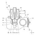
- the main valve body 420 integrally has a body portion 421, an upper flange portion 422, and a lower flange portion 423.
- the body portion 421 has a columnar shape.
- the upper flange portion 422 has an annular shape.
- the inner peripheral edge of the upper flange portion 422 is connected to the upper portion of the body portion 421 .
- the lower flange portion 423 has an annular shape.
- the inner peripheral edge of the lower flange portion 423 is connected to the lower portion of the body portion 421 .
- the trunk portion 421 has a pilot passage 425 .
- the upper flange portion 422 has a pressure equalizing passage 426 .
- An annular plate-shaped packing is arranged on the lower flange portion 423 .
- the case 432 has a cylindrical shape with an open lower end and a closed upper end.
- a small-diameter cylindrical portion 431 b of the fixed core 431 is arranged inside the lower end portion of the case 432 .
- a lower end of the case 432 is joined to the fixed core 431 .
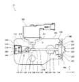
- the valve body 520 In the passing passage 150, when the pressure of the refrigerant at the passing inlet opening 181 becomes smaller than the refrigerant pressure at the passing outlet opening 182, the valve body 520 is pushed toward the passing inlet opening 181 (rearward) by the refrigerant, and the coil spring 530 expands. As a result, the valve portion 521 comes into contact with the valve seat 513 and the passageway 150 is closed. This inhibits the flow of refrigerant from the passage outlet opening 182 to the passage inlet opening 181 in the passage passage 150 .
- the discharge port of the compressor 20 is connected to the inlet of the indoor condenser 30 via a pipe P11.
- the compressor 20 sucks refrigerant, compresses the refrigerant, and discharges a high-temperature, high-pressure refrigerant.
- the indoor condenser 30 releases the heat of the refrigerant discharged by the compressor 20 .
- the indoor condenser 30 heats the blown air to the passenger compartment.
- the outlet of the indoor condenser 30 is connected to the inlet of the indoor evaporator 40 via a pipe P12.
- a check valve 60 and a flow control valve 70 are arranged in the pipe P12.
- the check valve 60 permits the flow of refrigerant from the indoor condenser 30 to the indoor evaporator 40 in the pipe P12 and prohibits the flow of refrigerant from the indoor evaporator 40 to the indoor condenser 30 .
- the flow control valve 70 can steplessly change the passage area of the pipe P12. Refrigerant flows through the interior of the indoor evaporator 40, and heat is exchanged between the refrigerant and the air blown to the passenger compartment. The indoor evaporator 40 cools the blown air.
- the outlet of the indoor evaporator 40 is connected to the inlet opening 171 of the valve device 10 via a pipe P13.
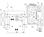
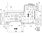
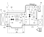
- the controller of the air conditioner 1 closes the refrigerant expansion passage 130 by the first on-off valve unit 300 of the valve device 10, closes the bypass passage 140 by the second on-off valve unit 400, and closes the pipe P12 by the flow control valve 70. is set to a size that allows the refrigerant to expand, and the on-off valve 80 opens the pipe P17. Then, the control device operates the compressor 20 to circulate the refrigerant. As shown in FIG. 2 , in the cooling mode, the refrigerant passes through the compressor 20, the indoor condenser 30, the check valve 60, the flow control valve 70, the indoor evaporator 40, and the on-off valve 80 in order, and then into the compressor 20. return. In the cooling mode, the blown air is cooled by the indoor evaporator 40 and then sent to the passenger compartment.
- the plurality of valve units are check valves that allow the flow of refrigerant from the passage inlet opening 181 to the passage outlet opening 182 in the passage passage 150 and prohibit the flow of refrigerant from the passage outlet opening 182 to the passage inlet opening 181. Also contains units. By doing so, it is possible to suppress the reverse flow of the coolant and allow the coolant to flow in the normal direction.
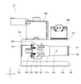
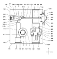
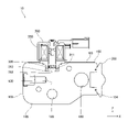
- Pilot valve body 336 Fixed iron core 336a Spring receiving member 337 Valve opening spring 338 Plunger spring 400 Second on-off valve unit 411 Second on-off valve chamber 412 Second On-off valve opening 413 Second on-off valve seat 414 Back pressure chamber 417 Connection opening 420 Main valve body 421 Body 422 Upper flange 423 Lower flange 425 Pilot passage , 426... Equalizing passage, 430... Valve body driving part, 431... Fixed iron core, 431a... Large diameter cylindrical part, 431b... Small diameter cylindrical part, 432... Case, 433... Plunger, 434... Electromagnetic coil, 435... Pilot valve body , 436... valve stem, 437... valve opening spring, 438... plunger spring, 500... check valve unit, 513... valve seat, 520... valve body, 521... valve portion, 530... coil spring, 540... support member, P11 ⁇ P17... Piping
Landscapes
- Engineering & Computer Science (AREA)
- Physics & Mathematics (AREA)
- Mechanical Engineering (AREA)
- Thermal Sciences (AREA)
- General Engineering & Computer Science (AREA)
- Fluid Mechanics (AREA)
- Temperature-Responsive Valves (AREA)
Abstract
Description
複数の冷媒通路を有する1つの弁本体と、
前記弁本体に取り付けられた複数の弁ユニットと、を有し、
前記複数の冷媒通路が、
前記弁本体の外面に配置された入口開口に接続された入口通路と、
前記弁本体の外面に配置された出口開口に接続された出口通路と、
前記入口通路と前記出口通路とを接続する冷媒膨張通路と、
前記入口通路と前記出口通路とを接続するバイパス通路と、を含み、
前記複数の弁ユニットが、
前記冷媒膨張通路の通路面積を変更可能な膨張弁ユニットと、
前記冷媒膨張通路を開閉可能な第1開閉弁ユニットと、
前記バイパス通路を開閉可能な第2開閉弁ユニットと、を含むことを特徴とする。
前記複数の冷媒通路が、通過通路をさらに含み、
前記通過通路が、前記弁本体の外面に配置された通過入口開口と前記弁本体の外面に配置された通過出口開口とを接続し、
前記膨張弁ユニットが、前記通過通路を流れる冷媒の温度に応じて前記冷媒膨張通路の通路面積を変更する、ことが好ましい。
前記複数の弁ユニットが、前記通過通路における前記通過入口開口から前記通過出口開口への冷媒の流れを許容しかつ前記通過出口開口から前記通過入口開口への冷媒の流れを禁止する逆止弁ユニットをさらに含むことが好ましい。
前記入口開口が、前記弁本体の平面状の第1外面に配置され、
前記出口開口が、前記弁本体の前記第1外面と平行な平面状の第2外面に配置され、
前記入口通路が、前記入口開口から前記第1外面の法線方向に直線状に延びる柱形状を有し、
前記出口通路が、前記出口開口から前記第2外面の法線方向に直線状に延びる柱形状を有し、
前記入口通路の中心線と前記出口通路の中心線とを含む1つの仮想平面が、前記弁本体の前記第1外面に対して直角な平面状の第3外面と非平行でかつ前記弁本体の前記第1外面および前記第3外面に対して直角な平面状の第4外面と非平行である、ことが好ましい。
前記入口開口が、前記弁本体の平面状の第1外面に配置され、
前記入口通路が、前記入口開口から前記第1外面の法線方向に直線状に延びる柱形状を有し、
前記バイパス通路が、前記第2開閉弁ユニットの弁体が配置される柱形状の弁室を有し、
前記弁室の一部が、前記入口通路と重なっている、ことが好ましい。
圧縮機と、室内凝縮器と、室内蒸発器と、室外熱交換器と、逆止弁と、流量調整弁と、開閉弁と、前記弁装置と、を有する空調装置であって、
前記圧縮機の吐出口が、前記室内凝縮器の入口と接続され、
前記室内凝縮器の出口が、前記逆止弁および前記流量調整弁を介して前記室内蒸発器の入口と接続され、
前記入口開口が、前記室内蒸発器の出口と接続され、
前記出口開口が、前記室外熱交換器の入口と接続され、
前記通過入口開口が、前記室外熱交換器の出口と接続され、
前記通過出口開口が、前記圧縮機の吸入口と接続され、
前記室内蒸発器の出口と前記圧縮機の吸入口とが前記開閉弁を介して接続されていることを特徴とする。
前記入口開口と前記通過出口開口とが、1つの外面に配置され、
前記出口開口と前記通過入口開口とが、他の1つの外面に配置される、ことが好ましい。
Claims (7)
- 複数の冷媒通路を有する1つの弁本体と、
前記弁本体に取り付けられた複数の弁ユニットと、を有し、
前記複数の冷媒通路が、
前記弁本体の外面に配置された入口開口に接続された入口通路と、
前記弁本体の外面に配置された出口開口に接続された出口通路と、
前記入口通路と前記出口通路とを接続する冷媒膨張通路と、
前記入口通路と前記出口通路とを接続するバイパス通路と、を含み、
前記複数の弁ユニットが、
前記冷媒膨張通路の通路面積を変更可能な膨張弁ユニットと、
前記冷媒膨張通路を開閉可能な第1開閉弁ユニットと、
前記バイパス通路を開閉可能な第2開閉弁ユニットと、を含むことを特徴とする弁装置。 - 前記複数の冷媒通路が、通過通路をさらに含み、
前記通過通路が、前記弁本体の外面に配置された通過入口開口と前記弁本体の外面に配置された通過出口開口とを接続し、
前記膨張弁ユニットが、前記通過通路を流れる冷媒の温度に応じて前記冷媒膨張通路の通路面積を変更する、請求項1に記載の弁装置。 - 前記複数の弁ユニットが、前記通過通路における前記通過入口開口から前記通過出口開口への冷媒の流れを許容しかつ前記通過出口開口から前記通過入口開口への冷媒の流れを禁止する逆止弁ユニットをさらに含む、請求項2に記載の弁装置。
- 前記入口開口が、前記弁本体の平面状の第1外面に配置され、
前記出口開口が、前記弁本体の前記第1外面と平行な平面状の第2外面に配置され、
前記入口通路が、前記入口開口から前記第1外面の法線方向に直線状に延びる柱形状を有し、
前記出口通路が、前記出口開口から前記第2外面の法線方向に直線状に延びる柱形状を有し、
前記入口通路の中心線と前記出口通路の中心線とを含む1つの仮想平面が、前記弁本体の前記第1外面に対して直角な平面状の第3外面と非平行でかつ前記弁本体の前記第1外面および前記第3外面に対して直角な平面状の第4外面と非平行である、請求項1~請求項3のいずれか一項に記載の弁装置。 - 前記入口開口が、前記弁本体の平面状の第1外面に配置され、
前記入口通路が、前記入口開口から前記第1外面の法線方向に直線状に延びる柱形状を有し、
前記バイパス通路が、前記第2開閉弁ユニットの弁体が配置される柱形状の弁室を有し、
前記弁室の一部が、前記入口通路と重なっている、請求項1~請求項3のいずれか一項に記載の弁装置。 - 圧縮機と、室内凝縮器と、室内蒸発器と、室外熱交換器と、逆止弁と、流量調整弁と、開閉弁と、請求項2に記載の弁装置と、を有する空調装置であって、
前記圧縮機の吐出口が、前記室内凝縮器の入口と接続され、
前記室内凝縮器の出口が、前記逆止弁および前記流量調整弁を介して前記室内蒸発器の入口と接続され、
前記入口開口が、前記室内蒸発器の出口と接続され、
前記出口開口が、前記室外熱交換器の入口と接続され、
前記通過入口開口が、前記室外熱交換器の出口と接続され、
前記通過出口開口が、前記圧縮機の吸入口と接続され、
前記室内蒸発器の出口と前記圧縮機の吸入口とが前記開閉弁を介して接続されていることを特徴とする空調装置。 - 前記入口開口と前記通過出口開口とが、1つの外面に配置され、
前記出口開口と前記通過入口開口とが、他の1つの外面に配置される、請求項6に記載の空調装置。
Priority Applications (2)
| Application Number | Priority Date | Filing Date | Title |
|---|---|---|---|
| JP2022540652A JP7139000B1 (ja) | 2021-05-18 | 2022-03-25 | 弁装置および空調装置 |
| DE112022002644.8T DE112022002644T5 (de) | 2021-05-18 | 2022-03-25 | Ventilvorrichtung und Klimatisierungsvorrichtung |
Applications Claiming Priority (2)
| Application Number | Priority Date | Filing Date | Title |
|---|---|---|---|
| JP2021-084193 | 2021-05-18 | ||
| JP2021084193 | 2021-05-18 |
Publications (1)
| Publication Number | Publication Date |
|---|---|
| WO2022244476A1 true WO2022244476A1 (ja) | 2022-11-24 |
Family
ID=84141214
Family Applications (1)
| Application Number | Title | Priority Date | Filing Date |
|---|---|---|---|
| PCT/JP2022/014739 Ceased WO2022244476A1 (ja) | 2021-05-18 | 2022-03-25 | 弁装置および空調装置 |
Country Status (1)
| Country | Link |
|---|---|
| WO (1) | WO2022244476A1 (ja) |
Citations (3)
| Publication number | Priority date | Publication date | Assignee | Title |
|---|---|---|---|---|
| JPH102623A (ja) * | 1996-06-11 | 1998-01-06 | Mitsubishi Heavy Ind Ltd | 冷凍装置 |
| JP2000130889A (ja) * | 1998-10-29 | 2000-05-12 | Tgk Co Ltd | バイパス付冷凍サイクルの弁取付構造 |
| JP2013072531A (ja) * | 2011-09-29 | 2013-04-22 | Fuji Koki Corp | 弁装置 |
-
2022
- 2022-03-25 WO PCT/JP2022/014739 patent/WO2022244476A1/ja not_active Ceased
Patent Citations (3)
| Publication number | Priority date | Publication date | Assignee | Title |
|---|---|---|---|---|
| JPH102623A (ja) * | 1996-06-11 | 1998-01-06 | Mitsubishi Heavy Ind Ltd | 冷凍装置 |
| JP2000130889A (ja) * | 1998-10-29 | 2000-05-12 | Tgk Co Ltd | バイパス付冷凍サイクルの弁取付構造 |
| JP2013072531A (ja) * | 2011-09-29 | 2013-04-22 | Fuji Koki Corp | 弁装置 |
Similar Documents
| Publication | Publication Date | Title |
|---|---|---|
| JP3794100B2 (ja) | 電磁弁一体型膨張弁 | |
| JP3882299B2 (ja) | 電磁弁一体型膨張弁 | |
| CN108713118B (zh) | 电磁阀、使用该电磁阀的制冷装置以及使用该制冷装置的车用空调装置 | |
| JP2007512489A (ja) | 可変容量形コンプレッサの制御に適したマイクロバルブ・デバイス | |
| EP2479520B1 (en) | Three-way electromagnetic valve | |
| JP2020139641A (ja) | ヒートポンプシステム | |
| US6574976B2 (en) | Refrigerant cycle system and valve device for the same | |
| JP7139000B1 (ja) | 弁装置および空調装置 | |
| JP4056378B2 (ja) | 差圧弁 | |
| JP2020060364A (ja) | 多段膨張装置付熱交換器、冷媒サイクル、および温度調節システム | |
| WO2022244476A1 (ja) | 弁装置および空調装置 | |
| JP3882573B2 (ja) | 電磁弁一体型膨張弁 | |
| JP5570314B2 (ja) | 三方電磁弁 | |
| JP2014020738A (ja) | 膨張弁 | |
| WO1996011369A1 (en) | Air-conditioner | |
| JP3249483B2 (ja) | 複合電磁弁及び複合電磁弁の制御方法 | |
| JP2000283606A (ja) | 冷凍サイクル装置 | |
| JPH11125472A (ja) | 冷凍サイクルの冷媒流量制御装置 | |
| JP7555636B2 (ja) | 弁装置組立体 | |
| JP7309250B2 (ja) | 弁装置および空調装置 | |
| WO2023058447A1 (ja) | 弁装置 | |
| KR102877045B1 (ko) | 밸브 장치 | |
| WO2022215562A1 (ja) | 弁装置およびその製造方法 | |
| JP2004028488A (ja) | 冷凍サイクル装置に用いる弁装置 | |
| JP2001199232A (ja) | ヒートポンプ装置 |
Legal Events
| Date | Code | Title | Description |
|---|---|---|---|
| ENP | Entry into the national phase |
Ref document number: 2022540652 Country of ref document: JP Kind code of ref document: A |
|
| 121 | Ep: the epo has been informed by wipo that ep was designated in this application |
Ref document number: 22804394 Country of ref document: EP Kind code of ref document: A1 |
|
| WWE | Wipo information: entry into national phase |
Ref document number: 112022002644 Country of ref document: DE |
|
| 122 | Ep: pct application non-entry in european phase |
Ref document number: 22804394 Country of ref document: EP Kind code of ref document: A1 |