WO2022244177A1 - 冷凍システム - Google Patents
冷凍システム Download PDFInfo
- Publication number
- WO2022244177A1 WO2022244177A1 PCT/JP2021/019146 JP2021019146W WO2022244177A1 WO 2022244177 A1 WO2022244177 A1 WO 2022244177A1 JP 2021019146 W JP2021019146 W JP 2021019146W WO 2022244177 A1 WO2022244177 A1 WO 2022244177A1
- Authority
- WO
- WIPO (PCT)
- Prior art keywords
- refrigerant
- air
- refrigeration system
- temperature
- leakage
- Prior art date
- Legal status (The legal status is an assumption and is not a legal conclusion. Google has not performed a legal analysis and makes no representation as to the accuracy of the status listed.)
- Ceased
Links
Images




Classifications
-
- F—MECHANICAL ENGINEERING; LIGHTING; HEATING; WEAPONS; BLASTING
- F25—REFRIGERATION OR COOLING; COMBINED HEATING AND REFRIGERATION SYSTEMS; HEAT PUMP SYSTEMS; MANUFACTURE OR STORAGE OF ICE; LIQUEFACTION SOLIDIFICATION OF GASES
- F25B—REFRIGERATION MACHINES, PLANTS OR SYSTEMS; COMBINED HEATING AND REFRIGERATION SYSTEMS; HEAT PUMP SYSTEMS
- F25B49/00—Arrangement or mounting of control or safety devices
- F25B49/02—Arrangement or mounting of control or safety devices for compression type machines, plants or systems
Definitions
- the present disclosure relates to a refrigeration system having a refrigerant circuit in which combustible refrigerant circulates.
- Patent Document 1 there is a refrigeration system equipped with a refrigerant circuit in which combustible refrigerant circulates (see Patent Document 1, for example).
- the refrigeration system of Patent Document 1 includes an air conditioner, a ventilator, and a refrigerant leakage detection device.
- a ventilator when a refrigerant leak is detected by a refrigerant leak detection device, a ventilator is operated to discharge combustible refrigerant from a space in which the refrigerant leak has occurred.
- Patent Document 1 when the air volume of the ventilation device is insufficient during the operation of the ventilation device when refrigerant leakage is detected, the leaked flammable refrigerant is released into the space by increasing the air volume of the air conditioner. It is designed to prevent it from accumulating in the space and to discharge it from the space.
- a ventilation device is essential, so it is difficult to discharge the flammable refrigerant to the outside of the space where the ventilation device is not installed, such as an underground space or a warehouse. If the flammable refrigerant cannot be discharged to the outside of the space, the flammable refrigerant stays in the space, which is insufficient as a countermeasure against refrigerant leakage.
- the present disclosure has been made to solve the above problems, and provides a refrigeration system that can reduce the amount of flammable refrigerant in a space where refrigerant leakage occurs without a ventilation device. With the goal.
- a refrigeration system includes a compressor, a condenser, a decompression device, and an evaporator, which are connected by refrigerant pipes and have a refrigerant circuit in which a combustible refrigerant circulates;
- a refrigerant leak detection device that detects refrigerant leakage from the refrigerant circuit, and an air cleaning device that starts operating when refrigerant leakage is detected by the refrigerant leakage detection device and removes flammable refrigerant from the taken air. It is.
- the air cleaning device when a refrigerant leak is detected, the air cleaning device starts operating and removes the flammable refrigerant from the taken air. It is possible to reduce the amount of volatile refrigerant.
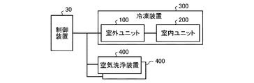
- FIG. 1 is a schematic configuration diagram of a refrigeration system according to Embodiment 1;
- FIG. 2 is an explanatory diagram of a control system of the refrigeration system according to Embodiment 1;
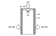
- FIG. 1 is a diagram showing an example of an air washing device according to Embodiment 1;
- FIG. FIG. 4 is a diagram showing another example of the air washing device according to Embodiment 1;
- 4 is a flow chart showing the operation of the refrigeration system according to Embodiment 1;
- 4 is a diagram showing another configuration example of the refrigeration system according to Embodiment 1;
- FIG. 4 is a diagram showing another configuration example of the refrigeration system according to Embodiment 1;
- FIG. FIG. 2 is a schematic configuration diagram of a refrigeration system according to Embodiment 2;
- 8 is a flow chart showing the operation of the refrigeration system according to Embodiment 2;
- FIG. 1 is a schematic configuration diagram of a refrigeration system according to Embodiment 1.
- FIG. FIG. 2 is an explanatory diagram of a control system of the refrigeration system according to Embodiment 1.
- the refrigeration system 50 includes a refrigeration device 300 and an air washing device 400 .
- the refrigerator 300 includes an outdoor unit 100 and an indoor unit 200 such as a showcase.
- the outdoor unit 100 is arranged in the outdoor space 60 .
- the indoor unit 200 is arranged in an indoor space 70 such as a machine room or warehouse.
- the air cleaning device 400 is arranged in both the indoor space 70 and the outdoor space 60 .
- Air washing device 400 may be arranged in one of indoor space 70 and outdoor space 60 .
- the outdoor unit 100 and the indoor unit 200 are connected by a liquid extension pipe 12 and a gas extension pipe 13.
- the outdoor unit 100 includes a compressor 1 , an oil separator 2 , a condenser 3 , a liquid receiver 4 , a subcooling heat exchanger 5 , a fan 3 a, a dryer 6 and an accumulator 9 .
- the indoor unit 200 also includes a decompression device 7 configured by an expansion valve, a capillary tube, or the like, an evaporator 8, and a fan 8a.
- Compressor 1 oil separator 2, condenser 3, liquid receiver 4, subcooling heat exchanger 5, dryer 6, decompression device 7, evaporator 8 and accumulator 9 are connected by refrigerant pipe 10, and the refrigerant is A circulating refrigerant circuit A is configured.
- a highly flammable refrigerant such as propane (R290) or isobutane is used.
- a slightly flammable refrigerant such as R32, R1234yf or R463A-J may be used as the refrigerant.
- the highly flammable refrigerant and the mildly flammable refrigerant are collectively referred to as flammable refrigerant without distinction.
- the compressor 1 sucks refrigerant and compresses the refrigerant to a high temperature and high pressure state.
- the oil separator 2 separates oil contained in the refrigerant discharged from the compressor 1 .
- the condenser 3 cools and condenses the refrigerant discharged from the compressor 1 .
- the liquid receiver 4 is a container that is arranged between the condenser 3 and the subcooling heat exchanger 5 and stores excess refrigerant liquefied in the refrigerant circuit A.
- the supercooling heat exchanger 5 has a high-pressure side channel through which a high-pressure refrigerant flows and a low-pressure side channel through which a low-pressure refrigerant flows, and performs heat exchange between the high-pressure refrigerant and the low-pressure refrigerant.
- the dryer 6 removes foreign matter contained in the refrigerant. Foreign matter corresponds to impurities, moisture, or the like.
- Accumulator 9 stores excess refrigerant.
- the evaporator 8 heats and evaporates the refrigerant flowing out of the decompression device 7 .
- the refrigerant circuit A further includes an injection pipe 5b branched from between the supercooling heat exchanger 5 and the dryer 6 and connected to the suction side of the compressor 1 via the low pressure side flow path of the supercooling heat exchanger 5. I have.
- the injection pipe 5b is connected to a decompression device 5a composed of, for example, an expansion valve.
- the refrigeration system 300 also includes a first temperature sensor TH1, a second temperature sensor TH2, a third temperature sensor TH3, and a fourth temperature sensor TH4. Temperature information measured by the first temperature sensor TH1, the second temperature sensor TH2, the third temperature sensor TH3, and the fourth temperature sensor TH4 is input to the control device 30, which will be described later.
- the first temperature sensor TH1 is provided at any position in the flow path from the outlet side of the condenser 3 to the inlet side of the supercooling heat exchanger 5, and measures the temperature of the refrigerant.
- the temperature measured by the first temperature sensor TH1 is referred to as "supercooling heat exchanger inlet temperature th1".
- the pressure may be measured by a pressure sensor and the value converted to the saturation temperature may be used as the subcooling heat exchanger inlet temperature th1.
- the second temperature sensor TH2 is provided at any position in the flow path from the outlet side of the subcooling heat exchanger 5 to the inlet side of the decompression device 7, and measures the temperature of the refrigerant.
- the temperature measured by the second temperature sensor TH2 is referred to as "subcooling heat exchanger outlet temperature th2".
- the third temperature sensor TH3 measures the temperature of the air that exchanges heat with the refrigerant in the condenser 3.
- the temperature measured by the third temperature sensor TH3 is referred to as "outside temperature th3".
- the fourth temperature sensor TH4 measures the temperature of the refrigerant injected into the compressor 1.
- injection temperature tc the temperature measured by the fourth temperature sensor TH4 is referred to as "injection temperature tc”.
- the air cleaning device 400 is a device that removes combustible refrigerant from the air taken inside the air cleaning device 400 .
- the configuration of the air washing device 400 is shown in FIGS. 3 and 4 below.
- FIG. 3 is a diagram showing an example of the air washing device 400 according to Embodiment 1.
- FIG. FIG. 4 is a diagram showing another example of the air washing device 400 according to Embodiment 1.
- the air cleaning device 400 includes a filter 401, a fan motor 402, and a fan 403 driven by the fan motor 402 to take in air from the outside and pass it through the filter 401.
- Filter 401 removes combustible refrigerant from air passing through filter 401 .
- Air cleaning device 400 may further include a filter that removes dust and the like from the air taken into air cleaning device 400 .
- the filter 401 has an adsorbent that adsorbs the flammable refrigerant, and the adsorbent adsorbs the flammable refrigerant, thereby removing the flammable refrigerant from the air passing through the filter 401 and cleaning the air.
- the adsorbent is, for example, zeolite or activated carbon.
- the filter 401 has a decomposition catalyst that chemically reacts with the combustible refrigerant to decompose the refrigerant into incombustibles. It may be removed to wash the air.
- the decomposition catalyst When the combustible refrigerant is propane gas, a cobalt-based or nickel-based catalyst is used as the decomposition catalyst.
- the decomposition catalyst is used after being heated.
- the air cleaning device 400 may include both the filter 401 having the adsorbent and the filter 401 having the decomposition catalyst.
- the air cleaning device 400 includes a sideward blowing type and a topward blowing type, which are shown in FIGS. 3 and 4, respectively.
- FIG. 3 shows a side blowing type air cleaning device 400 .
- air containing a combustible refrigerant is sucked into the air cleaning device 400 from the side as indicated by the white arrow.
- the sucked air containing the flammable refrigerant passes through the filter 401 to remove the flammable refrigerant and is washed, and the washed air is blown out laterally as it is.
- FIG. 4 shows an air washing device 400 of a top-direction blowing type.
- air containing a combustible refrigerant is sucked into the air washing device 400 from both left and right sides as indicated by white arrows.
- the sucked air containing the flammable refrigerant passes through the filter 401 to remove the flammable refrigerant and is washed, and the washed air is blown out from above.
- the air cleaner 400 is arranged adjacent to the indoor unit 200 from the viewpoint of early removal of the leaked combustible refrigerant.
- the air washing device 400 is arranged in the outdoor space 60 , it is arranged adjacent to the outdoor unit 100 .
- the air cleaning device 400 is arranged adjacent to the refrigerating device 300 .
- the air washing device 400 is arranged at a height equal to or lower than the arrangement position of the refrigerating device 300 .
- the air washing device 400 is arranged at a height equal to or lower than the arrangement position of the indoor unit 200 .
- the air cleaning device 400 when the air cleaning device 400 is arranged in the outdoor space 60 , the air cleaning device 400 is arranged at a height equal to or lower than the installation position of the outdoor unit 100 . Since the flammable refrigerant is heavier than air, the flammable refrigerant can be quickly removed by arranging the air washing device 400 at the above position.
- the refrigeration system 50 further includes a control device 30 that controls the entire refrigeration system.
- the control device 30 is composed of, for example, a microcomputer, and includes a CPU, RAM, ROM, and the like.
- the ROM stores a control program and a program corresponding to the flowchart of FIG. 5, which will be described later.
- the control device 30 includes a refrigerant leak detection device 31 and a cleaning control device 32.
- the refrigerant leakage detection device 31 detects refrigerant leakage from the refrigerant circuit A based on temperature information measured by the temperature sensors TH1 to TH4.
- the cleaning control device 32 controls the air cleaning device 400 based on the detection result of the refrigerant leak detection device 31 . Further, when refrigerant leakage is detected by the refrigerant leakage detection device 31, the control device 30 issues a refrigerant leakage alarm from a display device (not shown), an audio output device (not shown), or the like.
- refrigerant leak detection operation in the refrigerant leak detection device 31 will be described.
- the refrigerant leakage detection operation in the refrigerant leakage detection device 31 is not particularly limited, and a conventionally known method disclosed in Japanese Patent Application Laid-Open No. 2012-132639, for example, can be employed. This well-known refrigerant leak detection method will be briefly described below.
- the refrigerant leak detection device 31 determines whether or not there is a refrigerant leak by using the fact that the subcooling efficiency ⁇ of the supercooling heat exchanger 5 decreases.
- the subcooling efficiency ⁇ of the supercooling heat exchanger 5 is " It is a value obtained by dividing by the "calculated temperature” and is represented by Equation 1 below. "The degree of supercooling of the refrigerant at the outlet of the supercooling heat exchanger 5" is the temperature difference between the supercooling heat exchanger inlet temperature th1 and the supercooling heat exchanger outlet temperature th2. “The degree of supercooling of the refrigerant at the outlet of the supercooling heat exchanger 5” is calculated by subcooling heat exchanger inlet temperature th1 ⁇ supercooling heat exchanger outlet temperature th2.
- the "calculated temperature” is the temperature difference between the subcooling heat exchanger inlet temperature th1 and the outside air temperature th3.
- the “calculated temperature” is calculated by subcooling heat exchanger inlet temperature th1 ⁇ outside air temperature th3.
- the injection temperature tc may be used instead of the outside air temperature th3. That is, the “calculated temperature” may be the temperature difference between the subcooling heat exchanger inlet temperature th1 and the injection temperature tc.
- the subcooling efficiency ⁇ when using the injection temperature tc is represented by the following Equation 2.
- the refrigerant leak detection device 31 uses the subcooling efficiency ⁇ calculated when the current operating state does not correspond to the undetectable condition described below as an effective value for refrigerant leak detection. Valid values for the subcooling efficiency ⁇ are greater than 0 and less than 1.5.
- the refrigerant leak detection device 31 calculates the subcooling efficiency ⁇ at a set detection cycle. Then, when all the subcooling efficiencies obtained at that time are valid values after the calculation of the set number of times (for example, 10 times) is completed, the effective values for the set number of times are used to calculate the average temperature efficiency of the subcooling. Calculate
- the refrigerant leak detection device 31 determines that there is a refrigerant leak. Since the calculation of the sub-cooling efficiency ⁇ is performed at the set detection cycle as described above, in other words, the refrigerant leak detection device 31 detects that the average temperature efficiency is less than the predetermined determination threshold continuously for the set period set in advance. At this time, it is determined that there is refrigerant leakage.
- the undetectable condition corresponds to, for example, a case where the compressor 1 is in a stopped state or a case where the temperature efficiency is not stable such as 30 minutes after starting.
- the refrigerant leakage detection device 31 calculates the subcooling efficiency ⁇ based on the temperature information measured by the temperature sensors TH1 to TH4, and detects the refrigerant leakage. good too. That is, the refrigerant leak detection device 31 may include, for example, a gas sensor that detects refrigerant concentration, and detect refrigerant leakage based on the refrigerant concentration detected by the gas sensor.
- FIG. 1 shows a configuration in which the refrigerant leak detection device 31 is provided on the outdoor unit 100 side, it may be provided on both the outdoor unit 100 and the indoor unit 200 .
- the high-temperature, high-pressure gas refrigerant discharged from the compressor 1 flows into the condenser 3 after the refrigerating machine oil contained in the refrigerant is separated by the oil separator 2 .
- the high-temperature and high-pressure gas refrigerant that has flowed into the condenser 3 is condensed by exchanging heat with the outdoor air blown from the fan 3 a in the condenser 3 and stored in the liquid receiver 4 as a high-pressure liquid refrigerant or a two-phase refrigerant. .
- the refrigerant flowing out of the liquid receiver 4 flows into the high-pressure side passage of the subcooling heat exchanger 5, and is supercooled by exchanging heat with the refrigerant passing through the low-pressure side passage of the subcooling heat exchanger 5. It becomes a high-pressure liquid refrigerant. Then, the high-pressure liquid refrigerant that has flowed out of the subcooling heat exchanger 5 flows into the dryer 6, where foreign matter is removed. The liquid refrigerant flowing out of the dryer 6 is decompressed by the decompression device 7 of the indoor unit 200 to become a low-temperature, low-pressure two-phase refrigerant, and flows into the evaporator 8 .
- the refrigerant that has flowed into the evaporator 8 exchanges heat with the indoor air blown from the fan 8 a and evaporates to become a low-temperature, low-pressure gas refrigerant and returns to the compressor 1 via the accumulator 9 .
- part of the refrigerant that has flowed out from the high-pressure side of the supercooling heat exchanger 5 is decompressed by the decompression device 5a and flows into the low-pressure side flow path of the supercooling heat exchanger 5. After exchanging heat with the refrigerant flowing through the side passage, the refrigerant is injected into the compressor 1 .
- the configuration of the refrigerant circuit A is not limited to the configuration shown in FIG.
- a four-way valve or the like for switching the coolant flow path may be provided to enable switching between the cooling operation and the heating operation.
- the refrigerant circuit A may be configured exclusively for heating.
- the outdoor heat exchanger installed in the outdoor unit 100 functions as an evaporator
- the indoor heat exchanger installed in the indoor unit 200 functions as a condenser.
- the refrigerant circuit A may have a configuration in which at least one of the oil separator 2, the liquid receiver 4 and the accumulator 9 is not provided.
- the refrigerant circuit A should just be the structure provided with the compressor 1, the condenser 3, the decompression device 5a, and the evaporator 8 at least.
- FIG. 5 is a flowchart showing the operation of the refrigeration system according to Embodiment 1.
- the refrigerant leak detection device 31 starts the refrigerant leak detection operation described above (step S1).
- the control device 30 issues a refrigerant leakage alarm from a display device (not shown), an audio output device (not shown), or the like (step S3) Let it be.
- the control device 30 starts a pump-down operation to recover the refrigerant in the refrigerant circuit A to the liquid receiver 4 (step S4).
- the pump-down operation is performed to suppress the amount of refrigerant leaking from the refrigerant circuit A.
- the cleaning control device 32 starts the operation of the air cleaning device 400 (step S5). Since it is unknown where the refrigerant leaks from in the refrigerant circuit A, the cleaning control device 32 starts the operation of the air cleaning devices 400 for both the indoor space 70 and the outdoor space 60 .
- the air washing device 400 sets the number of rotations of the fan motor 402 to the rated number of rotations, which is the maximum number of rotations for operation, and operates the fan 403 at full speed.
- the rotation speed of the fan motor 402 is desirably the rated rotation speed from the viewpoint of quickly removing the combustible refrigerant, but it is not limited to the rated rotation speed.
- the rotation speed of the fan motors 402 of all the air cleaning devices 400 may be set to the maximum operating rotation speed when refrigerant leakage is detected.
- the air cleaning device 400 stops operating after operating for a preset set time (step S6). Since the air washing device 400 confines the adsorbed refrigerant, it is configured so that it cannot be restarted until the filter 401 is replaced after the operation is stopped (step S6).
- step S4 After starting the pump-down operation in step S4, when recovery of the refrigerant in the refrigerant circuit A is completed, the control device 30 ends the pump-down operation (step S7). After the pump-down operation is stopped, the inspector repairs the refrigerant leak (step S8) and restarts the refrigeration system 300 (step S9).
- step S ⁇ b>4 the control device 30 may start the pump-down operation after a preset time has passed since the coolant leak detection device 31 detected a coolant leak.
- step S5 the operation of the air washing device 400 is not limited to the operation for the preset set time, and the operation time may be changed according to the refrigerant concentration in the indoor space 70. Further, even after stopping the pump-down operation of refrigerating device 300, operation of air cleaning device 400 may be continued for a preset time if necessary. Also, a sensor is installed to measure the concentration of the flammable refrigerant, and the operation of the air cleaning device 400 is continued until the measured concentration drops to a specific safe level concentration. 400 may be controlled to stop operation.
- the pump-down operation in step S4 is effective from the viewpoint of suppressing the amount of refrigerant leaked from the refrigerant circuit A when refrigerant leakage occurs, but it can be omitted.
- the refrigeration system 50 may be configured to operate the air washing device 400 at least when refrigerant leakage is detected.
- the refrigeration system 50 when a refrigerant leak is detected, the operation of the air cleaning device 400 is started to remove combustible refrigerant from the taken air. Therefore, the refrigeration system 50 can reduce the amount of flammable refrigerant in the space where the refrigerant leak occurs, and can improve safety without a ventilation device.
- the operation of the air cleaning devices 400 in both the outdoor space 60 and the indoor space 70 is started when refrigerant leakage is detected, but the following may be performed.
- the refrigerant leak detection device 31 is arranged as a gas sensor in both the indoor unit 200 and the outdoor unit 100, it is possible to identify which of the indoor unit 200 and the outdoor unit 100 has the refrigerant leak. In this case, the refrigeration system 50 may start the operation of only the air cleaning device 400 installed in the space where the refrigerant leak occurs.
- the refrigeration system 50 since the refrigeration system 50 starts pump-down operation when a refrigerant leak is detected, the refrigeration system 50 recovers the refrigerant in the refrigerant circuit A to the liquid receiver 4 at an early stage. It is possible to suppress the amount of refrigerant leakage from.
- the refrigeration system 50 of Embodiment 1 detects refrigerant leaks using the subcooling efficiency ⁇ , so that refrigerant leaks can be detected before flash gas is generated. Therefore, the refrigeration system 50 can reduce the amount of refrigerant released into the atmosphere, improve product reliability, and reduce cost loss.
- refrigeration system 50 is not limited to the configuration shown in FIG. 1 or 2, and can be modified, for example, as follows without departing from the gist of the present disclosure.
- the refrigerating device 300 is a refrigerating device exclusively for cooling, but it may be an air conditioner that air-conditions the room. Further, the refrigerating device 300 is not limited to the air-cooling refrigerating device described above, and may be a water-cooling refrigerating device.
- Embodiment 1 the configuration in which one indoor unit 200 is connected to one outdoor unit 100 has been described. Also good.
- the refrigerating apparatus 300 may configure the refrigerant circuit A by connecting the outdoor unit 100 and the locally prepared indoor unit 200 with the refrigerant pipes 10 at the time of on-site installation.
- the refrigerating device 300 can also be a remote condensing unit shown in FIG. 6 below.
- FIG. 6 is a refrigerant circuit diagram when the refrigerating apparatus according to Embodiment 1 is a remote condensing unit.
- the remote condensing unit comprises a compression unit 500 located in the interior space 70 .
- the compression unit 500 is provided with a configuration other than the condenser 3 and the third temperature sensor TH3 among the configurations included in the outdoor unit 100 in FIG. And it has the structure by which the condenser 3 and 3rd temperature sensor TH3 were installed in the outdoor unit 100A.
- the refrigerating apparatus 300 is a single unit having each device constituting the refrigerant circuit A and other attached devices in one housing like a cooling unit, which are connected by the refrigerant pipe 10. good too.
- the refrigeration system 50 may also include an air conditioner as shown in FIG. 7 below.
- FIG. Refrigerating system 50 includes refrigerating device 300 and air cleaning device 400 as well as air conditioner 800 for air conditioning in the room.
- the air conditioner 800 has an outdoor unit 600 and an indoor unit 700 .
- the outdoor unit 600 and the indoor unit 700 are provided with a refrigerant circuit (not shown) similar to the refrigerant circuit A, and the refrigerant circulates in the refrigerant circuit to perform indoor air conditioning.
- the air conditioner 800 allows air taken in from the outside to pass through a heat exchanger in a refrigerant circuit to adjust the temperature of the air, and blows out the temperature-adjusted air to the outside.
- Air conditioner 800 is connected to and controlled by control device 30 .
- the outdoor unit 600 and the indoor unit 700 are provided with fans for blowing air to the heat exchangers provided therein.
- the air cleaning device 400 may be incorporated into the air conditioner 800 .
- the air cleaning device 400 is incorporated in the air conditioner 800
- one or both of the outdoor unit 600 and the indoor unit 700 of the air conditioner 800 may be provided with the filter 401 .
- the fan 403 and the fan motor 402 of the air washing device 400 those provided in the outdoor unit 600 and the indoor unit 700 may be substituted.
- the filter 401 should be replaced periodically.
- the refrigeration system 50 may have a configuration in which the air cleaning device 400 is incorporated in the air conditioner 800, and may further include the air cleaning device 400 separately.
- the refrigerating device 300 provided in the refrigerating system 50 is a cooling device in Embodiment 1, it may be an air conditioner.
- the air cleaning device 400 may be incorporated into the air conditioner as described above.
- Embodiment 1 the operation of the air cleaning device 400 is started when a refrigerant leak is detected. good too.
- the indoor unit 200 is a showcase, the showcase fan is always running. good.
- a separate circulator may be provided near the air washing device 400, and after the refrigerant leak is detected, it may be operated so as to blow air in the direction of the adsorbent.
- the circulator may be in operation before the refrigerant leak is detected, or may be started in conjunction with the operation of the air washing device 400 after the detection.
- the refrigeration system 50 of Embodiment 1 includes the compressor 1, the condenser 3, the decompression device 7, and the evaporator 8, which are connected by the refrigerant pipe 10 and are combustible.
- a refrigerating device 300 having a refrigerant circuit A in which refrigerant circulates is provided.
- the refrigerating device 300 further includes a refrigerant leak detection device 31 that detects a refrigerant leak from the refrigerant circuit A of the refrigerating device 300, and when the refrigerant leak is detected by the refrigerant leak detection device 31, the refrigerating device 300 starts operating and extracts flammable air from the taken air. and an air washing device 400 for removing the toxic refrigerant.
- the refrigeration system 50 starts the operation of the air cleaning device 400 when a refrigerant leak is detected, and removes the combustible refrigerant from the taken air.
- the amount of combustible refrigerant in the space can be reduced.
- the refrigeration system 50 can constitute a highly safe system.
- the air washing device 400 is started to operate when refrigerant leakage is detected, it is possible to suppress the deterioration of the ability to adsorb or decompose the flammable refrigerant as compared with the case of constant operation, and to maintain the ability over a long period of time. can be maintained.
- the air cleaning device 400 includes a filter 401 having an adsorbent that adsorbs a combustible refrigerant, and a filter 401 having a decomposition catalyst that chemically reacts with the combustible refrigerant to decompose the combustible refrigerant into incombustibles. and/or
- the refrigeration system 50 can remove combustible refrigerant from the taken-in air because the air cleaner 400 is equipped with such a filter 401 .
- the refrigerating device 300 provided in the refrigerating system 50 is an air conditioner 800 that passes the air taken in from the outside through the condenser 3 or the evaporator 8 to adjust the temperature of the air, and blows out the temperature-adjusted air to the outside.
- Air cleaner 400 is provided in air conditioner 800 .
- the air cleaner 400 can be incorporated into the air conditioner 800 .
- the air cleaner 400 has a fan 403 that takes in air from the outside, and the fan 403 operates at full speed when a refrigerant leak is detected.
- the refrigeration system 50 can quickly reduce the amount of flammable refrigerant when refrigerant leakage occurs.
- the air washing device 400 is arranged at a height below the arrangement position of the refrigerating device 300 .
- the refrigeration system 50 can quickly reduce the flammable refrigerant that is heavier than air.
- the refrigeration system 50 performs a pump-down operation to recover the combustible refrigerant to the liquid receiver 4 when refrigerant leakage is detected.
- the refrigeration system 50 can suppress the amount of refrigerant leakage from the refrigerant circuit A when refrigerant leakage occurs.
- FIG. 8 is a schematic configuration diagram of a refrigeration system according to Embodiment 2.
- FIG. 8 is a schematic configuration diagram of a refrigeration system according to Embodiment 2.
- the second embodiment will be described with a focus on the configuration different from the first embodiment, and the configurations not described in the second embodiment are the same as those in the first embodiment.
- the refrigeration system 50 of the second embodiment has a configuration in which a leak detection agent circulates together with the combustible refrigerant in the refrigerant circuit A of the refrigeration system 50 of the first embodiment.
- a refrigeration system 50 includes a leakage detection agent injection device 20 .
- the control device 30 of the refrigeration system 50 of Embodiment 2 includes an injection control device 33 that controls the leakage detection agent injection device 20 .
- the leakage detection agent injection device 20 is a device that is connected to the refrigerant pipe 10 of the refrigerant circuit A and injects the leakage detection agent into the refrigerant pipe 10 .
- the leak detection agent is a fluorescent agent here, and emits light by ultraviolet rays emitted from an ultraviolet lamp. An inspector can easily identify the refrigerant leak location by irradiating the suspected refrigerant leakage location with ultraviolet light from an ultraviolet lamp. Leak detection agents may also be, for example, colorants, odorants, or bubbles in the air.
- the leakage detection agent charging device 20 is arranged downstream of the oil separator 2 so that the leakage detection agent 23 is not separated by the oil separator 2 . FIG.
- the leakage detection agent charging device 20 is connected to the refrigerant pipe 10 between the oil separator 2 and the condenser 3, but the refrigerant pipe between the evaporator 8 and the compressor 1 10 may be connected.
- the leak detection agent injection device 20 may be connected to the refrigerant pipe 10 on the downstream side of the oil separator 2 .
- the number of installed leakage detection agent injection devices 20 may be one as shown in FIG. 8, or may be multiple. When multiple units are installed, the leakage detection agent injection device 20 is divided into the outdoor unit 100 and the indoor unit 200 and arranged. In other words, the leakage detection agent injection device 20 is arranged in both the outdoor unit 100 and the indoor unit 200 . As a result, the refrigeration system 50 becomes a system that can more quickly identify the location where the refrigerant leak has occurred.
- the configuration of the leakage detection agent injection device 20 is not particularly limited, and a conventionally known configuration disclosed in Japanese Patent No. 6742519, for example, can be adopted. Hereinafter, the leakage detection agent injection device 20 that employs this known technique will be briefly described.
- the leakage detecting agent injection device 20 includes a container 20a in which the leakage detecting agent 23 is stored, two connection pipes 21 and 22 connecting the container 20a and the refrigerant pipe 10 of the refrigerant circuit A, and two connection pipes 21 , 22, and two control valves (not shown).
- a pressure difference is provided between an inflow port 21a, which is a connection port between one connection pipe 21 and the refrigerant pipe 10, and an outflow port 22a, which is a connection port between the other connection pipe 22 and the refrigerant pipe 10. . Due to this pressure difference, the refrigerant in the refrigerant pipe 10 flows into the container 20a of the leakage detection agent injection device.
- the control valve is closed in a normal state with no refrigerant leakage, and the leakage detection agent 23 is not introduced into the refrigerant circuit A.
- the control valve is opened, the refrigerant flowing through the refrigerant pipe 10 flows into the container 20a due to the pressure difference. Then, the refrigerant mixed with the leakage detection agent 23 flows out from the container 20 a and flows into the refrigerant pipe 10 .
- the refrigerant is mixed with oil in order to maintain the lubricity of the sliding portions in the compressor 1, and the leakage detecting agent 23 is mixed with the oil-mixed refrigerant.
- the supply control device 33 does not allow the leakage detection agent supply device 20 to supply the leakage detection agent 23 to the refrigerant circuit A in normal times when there is no refrigerant leakage.
- the supply control device 33 causes the leakage detection agent injection device 20 to supply the leakage detection agent 23 into the refrigerant circuit A when refrigerant leakage is detected.
- step S9 is a flowchart showing the operation of the refrigeration system according to Embodiment 2.
- the control device 30 starts the pump-down operation in step S4, starts the operation of the air washing device in step S5, and starts the operation of the leakage detecting agent injection device 20. (step S10).
- the control device 30 outputs a signal for driving the leakage detecting agent injection device 20 to the injection control device 33, and the injection control device 33 outputs an ON signal to the control valve of the leakage detection agent injection device 20. be done.
- the control valve of the leakage detecting agent charging device 20 is opened, and the leakage detecting agent 23 is charged into the refrigerant circuit A from the leakage detecting agent charging device 20 .
- the leakage detection agent 23 introduced into the refrigerant circuit A from the leakage detection agent injection device 20 also circulates, The leakage detection agent 23 leaks out from the location where the refrigerant leaks.
- the inspector identifies the refrigerant leak location using the ultraviolet lamp (step S11). After specifying the refrigerant leak point, the inspector stops the pump-down operation (step S7a) and repairs the leak point (step S8). After the leak is repaired, the inspector restarts the refrigeration system 300 (step S9).
- control device 30 may start the pump-down operation after the injection of the leakage detection agent 23 into the refrigerant circuit A is completed.
- the charging control device 33 may control the leakage detecting agent charging device 20 so that the leakage detecting agent 23 is continuously charged into the refrigerant circuit A for several minutes, for example.
- the supply control device 33 may control the leakage detection agent injection device 20 so that the leakage detection agent 23 is intermittently injected into the refrigerant circuit A at preset time intervals.
- the leakage detecting agent injection device 20 introduces the leakage detecting agent 23 into the refrigerant circuit A.
- the refrigeration system 50 of Embodiment 2 is configured so that the leakage detecting agent 23 circulates in the refrigerant circuit A. Any method of introducing the leakage detecting agent 23 into the refrigerant circuit A is acceptable. For example, when the compressor 1 is shipped, the leakage detection agent 23 is stored in the compressor 1 together with the refrigerant and the lubricating oil, and the leakage detection agent 23 is circulated in the refrigerant circuit A when the compressor 1 is operated. good too.
- the refrigeration system 50 is provided with the leakage detection agent injection device 20, and when a refrigerant leak is detected, leakage detection is performed.
- a configuration in which the agent 23 is introduced into the refrigerant circuit A is preferable.
- the refrigeration system 50 of Embodiment 2 can obtain the same effects as those of Embodiment 1, and also obtain the following effects by circulating the leakage detection agent 23 in the refrigerant circuit A.
- the leakage detection agent 23 leaks from the refrigerant leakage location, thereby identifying the refrigerant leakage location. Therefore, the refrigeration system 50 can further improve safety.
- the refrigeration system 50 is provided with the leakage detecting agent injection device 20, and the leakage detecting agent 23 is injected into the refrigerant circuit A when a refrigerant leak is detected. It is possible to suppress functional deterioration of the leakage detection agent 23 as compared with the configuration in which it continues to circulate inside. As a result, the refrigeration system 50 can stably detect refrigerant leaks over a long period of time. Further, if the function of the leakage detection agent 23 is deteriorated, it may take time to identify the refrigerant leak location. Early detection becomes possible.
- the leak detection agent injection device 20 when the leak detection agent injection device 20 is installed in each of the outdoor unit 100 and the indoor unit 200, the refrigerant leak location can be found more quickly.
Landscapes
- Engineering & Computer Science (AREA)
- Physics & Mathematics (AREA)
- Mechanical Engineering (AREA)
- Thermal Sciences (AREA)
- General Engineering & Computer Science (AREA)
- Air Conditioning Control Device (AREA)
Priority Applications (2)
| Application Number | Priority Date | Filing Date | Title |
|---|---|---|---|
| JP2023522111A JP7645995B2 (ja) | 2021-05-20 | 2021-05-20 | 冷凍システム |
| PCT/JP2021/019146 WO2022244177A1 (ja) | 2021-05-20 | 2021-05-20 | 冷凍システム |
Applications Claiming Priority (1)
| Application Number | Priority Date | Filing Date | Title |
|---|---|---|---|
| PCT/JP2021/019146 WO2022244177A1 (ja) | 2021-05-20 | 2021-05-20 | 冷凍システム |
Publications (1)
| Publication Number | Publication Date |
|---|---|
| WO2022244177A1 true WO2022244177A1 (ja) | 2022-11-24 |
Family
ID=84141522
Family Applications (1)
| Application Number | Title | Priority Date | Filing Date |
|---|---|---|---|
| PCT/JP2021/019146 Ceased WO2022244177A1 (ja) | 2021-05-20 | 2021-05-20 | 冷凍システム |
Country Status (2)
| Country | Link |
|---|---|
| JP (1) | JP7645995B2 (https=) |
| WO (1) | WO2022244177A1 (https=) |
Cited By (5)
| Publication number | Priority date | Publication date | Assignee | Title |
|---|---|---|---|---|
| US11971183B2 (en) | 2019-09-05 | 2024-04-30 | Trane International Inc. | Systems and methods for refrigerant leak detection in a climate control system |
| DE102023100551A1 (de) * | 2023-01-12 | 2024-07-18 | Vaillant Gmbh | Sorptive Abscheidung von gasförmigem Sicherheitskältemittel |
| US12117191B2 (en) | 2022-06-24 | 2024-10-15 | Trane International Inc. | Climate control system with improved leak detector |
| WO2025004228A1 (ja) * | 2023-06-28 | 2025-01-02 | 三菱電機株式会社 | 冷凍装置および空気調和装置 |
| US12487008B2 (en) | 2022-01-14 | 2025-12-02 | Trane International Inc. | Method of commissioning an HVAC system |
Citations (4)
| Publication number | Priority date | Publication date | Assignee | Title |
|---|---|---|---|---|
| JP2001033127A (ja) * | 1999-07-22 | 2001-02-09 | Mayekawa Mfg Co Ltd | 空調用アンモニア冷凍機の簡易アンモニア除害装置 |
| JP2001093039A (ja) * | 1999-09-22 | 2001-04-06 | Sanden Corp | 自動販売機 |
| JP2017053517A (ja) * | 2015-09-08 | 2017-03-16 | ジョンソンコントロールズ ヒタチ エア コンディショニング テクノロジー(ホンコン)リミテッド | 空気調和システム |
| WO2018225263A1 (ja) * | 2017-06-09 | 2018-12-13 | 三菱電機株式会社 | 冷凍装置および空気調和装置 |
Family Cites Families (1)
| Publication number | Priority date | Publication date | Assignee | Title |
|---|---|---|---|---|
| JP4300966B2 (ja) | 2003-10-10 | 2009-07-22 | パナソニック株式会社 | 冷却ユニットの製造方法 |
-
2021
- 2021-05-20 JP JP2023522111A patent/JP7645995B2/ja active Active
- 2021-05-20 WO PCT/JP2021/019146 patent/WO2022244177A1/ja not_active Ceased
Patent Citations (4)
| Publication number | Priority date | Publication date | Assignee | Title |
|---|---|---|---|---|
| JP2001033127A (ja) * | 1999-07-22 | 2001-02-09 | Mayekawa Mfg Co Ltd | 空調用アンモニア冷凍機の簡易アンモニア除害装置 |
| JP2001093039A (ja) * | 1999-09-22 | 2001-04-06 | Sanden Corp | 自動販売機 |
| JP2017053517A (ja) * | 2015-09-08 | 2017-03-16 | ジョンソンコントロールズ ヒタチ エア コンディショニング テクノロジー(ホンコン)リミテッド | 空気調和システム |
| WO2018225263A1 (ja) * | 2017-06-09 | 2018-12-13 | 三菱電機株式会社 | 冷凍装置および空気調和装置 |
Cited By (6)
| Publication number | Priority date | Publication date | Assignee | Title |
|---|---|---|---|---|
| US11971183B2 (en) | 2019-09-05 | 2024-04-30 | Trane International Inc. | Systems and methods for refrigerant leak detection in a climate control system |
| US12487008B2 (en) | 2022-01-14 | 2025-12-02 | Trane International Inc. | Method of commissioning an HVAC system |
| US12117191B2 (en) | 2022-06-24 | 2024-10-15 | Trane International Inc. | Climate control system with improved leak detector |
| DE102023100551A1 (de) * | 2023-01-12 | 2024-07-18 | Vaillant Gmbh | Sorptive Abscheidung von gasförmigem Sicherheitskältemittel |
| WO2025004228A1 (ja) * | 2023-06-28 | 2025-01-02 | 三菱電機株式会社 | 冷凍装置および空気調和装置 |
| WO2025004772A1 (ja) * | 2023-06-28 | 2025-01-02 | 三菱電機株式会社 | 冷凍装置および空気調和装置 |
Also Published As
| Publication number | Publication date |
|---|---|
| JPWO2022244177A1 (https=) | 2022-11-24 |
| JP7645995B2 (ja) | 2025-03-14 |
Similar Documents
| Publication | Publication Date | Title |
|---|---|---|
| WO2022244177A1 (ja) | 冷凍システム | |
| US11015828B2 (en) | Refrigeration system with utilization unit leak detection | |
| CN109844426B (zh) | 制冷装置 | |
| CN110291349B (zh) | 冷冻装置 | |
| US11536502B2 (en) | Refrigerant cycle apparatus | |
| JP6742519B2 (ja) | 冷凍装置および空気調和装置 | |
| EP3136010B1 (en) | Air-conditioning device | |
| GB2566201A (en) | Air conditioning device | |
| CN109073306A (zh) | 制冷循环装置 | |
| JP2016125694A (ja) | 空気調和装置の室内機 | |
| JP2019002639A (ja) | 空気調和機の冷媒漏洩検知方法、および、空気調和機 | |
| CN109642762A (zh) | 车用空调装置 | |
| JP6590706B2 (ja) | 冷凍サイクル装置、及び、冷凍サイクル装置のバイパス弁漏れ判定制御方法 | |
| US20040168446A1 (en) | Method for refrigerant and oil collecting operation and refrigerant and oil collection controller | |
| JP6570745B2 (ja) | 空気調和装置 | |
| JPH0719642A (ja) | 冷媒加熱式空気調和機 | |
| CN105180511A (zh) | 分体落地式空调器、冷媒回收方法以及冷媒回收装置 | |
| JP2015215111A (ja) | ヒートポンプ機器 | |
| JP2004044871A (ja) | 冷凍装置 | |
| JPH08233380A (ja) | 圧縮式冷凍機及びこの圧縮式冷凍機を用いた空調システム | |
| JP2004125215A (ja) | 冷蔵庫 | |
| CN118220231B (zh) | 轨道车辆空调机组 | |
| JP2004169974A (ja) | 冷凍装置 | |
| JP5454410B2 (ja) | 冷凍空調装置 | |
| KR20090022420A (ko) | 냉매량을 제어할 수 있는 실외 열교환기를 구비한 분리형멀티에어컨 |
Legal Events
| Date | Code | Title | Description |
|---|---|---|---|
| 121 | Ep: the epo has been informed by wipo that ep was designated in this application |
Ref document number: 21940791 Country of ref document: EP Kind code of ref document: A1 |
|
| WWE | Wipo information: entry into national phase |
Ref document number: 2023522111 Country of ref document: JP |
|
| NENP | Non-entry into the national phase |
Ref country code: DE |
|
| 122 | Ep: pct application non-entry in european phase |
Ref document number: 21940791 Country of ref document: EP Kind code of ref document: A1 |