WO2022239590A1 - 光吸収性組成物、光吸収膜、光吸収膜の製造方法、及び光学フィルタ - Google Patents
光吸収性組成物、光吸収膜、光吸収膜の製造方法、及び光学フィルタ Download PDFInfo
- Publication number
- WO2022239590A1 WO2022239590A1 PCT/JP2022/017540 JP2022017540W WO2022239590A1 WO 2022239590 A1 WO2022239590 A1 WO 2022239590A1 JP 2022017540 W JP2022017540 W JP 2022017540W WO 2022239590 A1 WO2022239590 A1 WO 2022239590A1
- Authority
- WO
- WIPO (PCT)
- Prior art keywords
- light
- group
- optical filter
- absorbing
- formula
- Prior art date
- Legal status (The legal status is an assumption and is not a legal conclusion. Google has not performed a legal analysis and makes no representation as to the accuracy of the status listed.)
- Ceased
Links
Images














Classifications
-
- G—PHYSICS
- G02—OPTICS
- G02B—OPTICAL ELEMENTS, SYSTEMS OR APPARATUS
- G02B5/00—Optical elements other than lenses
- G02B5/20—Filters
- G02B5/22—Absorbing filters
-
- B—PERFORMING OPERATIONS; TRANSPORTING
- B05—SPRAYING OR ATOMISING IN GENERAL; APPLYING FLUENT MATERIALS TO SURFACES, IN GENERAL
- B05D—PROCESSES FOR APPLYING FLUENT MATERIALS TO SURFACES, IN GENERAL
- B05D3/00—Pretreatment of surfaces to which liquids or other fluent materials are to be applied; After-treatment of applied coatings, e.g. intermediate treating of an applied coating preparatory to subsequent applications of liquids or other fluent materials
- B05D3/02—Pretreatment of surfaces to which liquids or other fluent materials are to be applied; After-treatment of applied coatings, e.g. intermediate treating of an applied coating preparatory to subsequent applications of liquids or other fluent materials by baking
-
- C—CHEMISTRY; METALLURGY
- C08—ORGANIC MACROMOLECULAR COMPOUNDS; THEIR PREPARATION OR CHEMICAL WORKING-UP; COMPOSITIONS BASED THEREON
- C08K—Use of inorganic or non-macromolecular organic substances as compounding ingredients
- C08K3/00—Use of inorganic substances as compounding ingredients
- C08K3/02—Elements
- C08K3/08—Metals
-
- C—CHEMISTRY; METALLURGY
- C08—ORGANIC MACROMOLECULAR COMPOUNDS; THEIR PREPARATION OR CHEMICAL WORKING-UP; COMPOSITIONS BASED THEREON
- C08K—Use of inorganic or non-macromolecular organic substances as compounding ingredients
- C08K5/00—Use of organic ingredients
- C08K5/04—Oxygen-containing compounds
- C08K5/13—Phenols; Phenolates
- C08K5/132—Phenols containing keto groups, e.g. benzophenones
-
- C—CHEMISTRY; METALLURGY
- C08—ORGANIC MACROMOLECULAR COMPOUNDS; THEIR PREPARATION OR CHEMICAL WORKING-UP; COMPOSITIONS BASED THEREON
- C08K—Use of inorganic or non-macromolecular organic substances as compounding ingredients
- C08K5/00—Use of organic ingredients
- C08K5/56—Organo-metallic compounds, i.e. organic compounds containing a metal-to-carbon bond
-
- C—CHEMISTRY; METALLURGY
- C08—ORGANIC MACROMOLECULAR COMPOUNDS; THEIR PREPARATION OR CHEMICAL WORKING-UP; COMPOSITIONS BASED THEREON
- C08L—COMPOSITIONS OF MACROMOLECULAR COMPOUNDS
- C08L101/00—Compositions of unspecified macromolecular compounds
-
- C—CHEMISTRY; METALLURGY
- C08—ORGANIC MACROMOLECULAR COMPOUNDS; THEIR PREPARATION OR CHEMICAL WORKING-UP; COMPOSITIONS BASED THEREON
- C08L—COMPOSITIONS OF MACROMOLECULAR COMPOUNDS
- C08L83/00—Compositions of macromolecular compounds obtained by reactions forming in the main chain of the macromolecule a linkage containing silicon with or without sulfur, nitrogen, oxygen or carbon only; Compositions of derivatives of such polymers
- C08L83/04—Polysiloxanes
-
- G—PHYSICS
- G02—OPTICS
- G02B—OPTICAL ELEMENTS, SYSTEMS OR APPARATUS
- G02B5/00—Optical elements other than lenses
- G02B5/20—Filters
- G02B5/208—Filters for use with infrared or ultraviolet radiation, e.g. for separating visible light from infrared and/or ultraviolet radiation
-
- G—PHYSICS
- G02—OPTICS
- G02B—OPTICAL ELEMENTS, SYSTEMS OR APPARATUS
- G02B5/00—Optical elements other than lenses
- G02B5/20—Filters
- G02B5/22—Absorbing filters
- G02B5/223—Absorbing filters containing organic substances, e.g. dyes, inks or pigments
-
- B—PERFORMING OPERATIONS; TRANSPORTING
- B05—SPRAYING OR ATOMISING IN GENERAL; APPLYING FLUENT MATERIALS TO SURFACES, IN GENERAL
- B05D—PROCESSES FOR APPLYING FLUENT MATERIALS TO SURFACES, IN GENERAL
- B05D2203/00—Other substrates
- B05D2203/30—Other inorganic substrates, e.g. ceramics, silicon
- B05D2203/35—Glass
-
- B—PERFORMING OPERATIONS; TRANSPORTING
- B05—SPRAYING OR ATOMISING IN GENERAL; APPLYING FLUENT MATERIALS TO SURFACES, IN GENERAL
- B05D—PROCESSES FOR APPLYING FLUENT MATERIALS TO SURFACES, IN GENERAL
- B05D2601/00—Inorganic fillers
- B05D2601/02—Inorganic fillers used for pigmentation effect, e.g. metallic effect
- B05D2601/10—Other metals
-
- B—PERFORMING OPERATIONS; TRANSPORTING
- B05—SPRAYING OR ATOMISING IN GENERAL; APPLYING FLUENT MATERIALS TO SURFACES, IN GENERAL
- B05D—PROCESSES FOR APPLYING FLUENT MATERIALS TO SURFACES, IN GENERAL
- B05D2601/00—Inorganic fillers
- B05D2601/20—Inorganic fillers used for non-pigmentation effect
- B05D2601/22—Silica
-
- B—PERFORMING OPERATIONS; TRANSPORTING
- B05—SPRAYING OR ATOMISING IN GENERAL; APPLYING FLUENT MATERIALS TO SURFACES, IN GENERAL
- B05D—PROCESSES FOR APPLYING FLUENT MATERIALS TO SURFACES, IN GENERAL
- B05D2601/00—Inorganic fillers
- B05D2601/20—Inorganic fillers used for non-pigmentation effect
- B05D2601/28—Metals
-
- B—PERFORMING OPERATIONS; TRANSPORTING
- B05—SPRAYING OR ATOMISING IN GENERAL; APPLYING FLUENT MATERIALS TO SURFACES, IN GENERAL
- B05D—PROCESSES FOR APPLYING FLUENT MATERIALS TO SURFACES, IN GENERAL
- B05D3/00—Pretreatment of surfaces to which liquids or other fluent materials are to be applied; After-treatment of applied coatings, e.g. intermediate treating of an applied coating preparatory to subsequent applications of liquids or other fluent materials
- B05D3/02—Pretreatment of surfaces to which liquids or other fluent materials are to be applied; After-treatment of applied coatings, e.g. intermediate treating of an applied coating preparatory to subsequent applications of liquids or other fluent materials by baking
- B05D3/0254—After-treatment
- B05D3/0272—After-treatment with ovens
-
- B—PERFORMING OPERATIONS; TRANSPORTING
- B05—SPRAYING OR ATOMISING IN GENERAL; APPLYING FLUENT MATERIALS TO SURFACES, IN GENERAL
- B05D—PROCESSES FOR APPLYING FLUENT MATERIALS TO SURFACES, IN GENERAL
- B05D5/00—Processes for applying liquids or other fluent materials to surfaces to obtain special surface effects, finishes or structures
- B05D5/06—Processes for applying liquids or other fluent materials to surfaces to obtain special surface effects, finishes or structures to obtain multicolour or other optical effects
Definitions
- the present invention relates to a light-absorbing composition, a light-absorbing film, a method for producing a light-absorbing film, and an optical filter.
- Various optical filters are placed in front of the solid-state imaging device to obtain images with good color reproducibility in imaging devices using solid-state imaging devices such as CCD (Charge Coupled Device) or CMOS (Complementary Metal Oxide Semiconductor).
- CCD Charge Coupled Device
- CMOS Complementary Metal Oxide Semiconductor
- a solid-state imaging device has spectral sensitivity in a wavelength range wider than human visibility corresponding to the visible light region. Therefore, in order to make the spectral sensitivity of a solid-state image pickup device in an image pickup device closer to human visibility, there is a known technique in which an optical filter that shields part of the infrared or ultraviolet light is arranged in front of the solid-state image pickup device. .
- an optical filter it was common to block infrared rays or ultraviolet rays using light reflection by a dielectric multilayer film.
- optical filters having a film containing a light absorbing agent Since the transmittance characteristics of an optical filter with a film containing a light absorbing agent are not easily affected by the angle of incidence, good images with little color change can be obtained even when light is incident obliquely on the optical filter in an imaging device. Obtainable.
- a light-absorbing optical filter that does not use a light-reflecting film can suppress the occurrence of ghosts and flares caused by multiple reflections by the light-reflecting film. Cheap.
- an optical filter having a film containing a light absorbing agent is advantageous in terms of miniaturization and thickness reduction of imaging devices.
- Patent Document 1 describes an optical filter having a light absorbing layer containing a light absorbing agent formed by a phosphonic acid having a phenyl group or a halogenated phenyl group (phenyl-based phosphonic acid) and copper ions. It is
- Patent Document 2 describes an optical filter having a UV-IR absorption layer capable of absorbing infrared rays and ultraviolet rays.
- the UV-IR absorbing layer contains UV-IR absorbers formed by phosphonic acid and copper ions.
- the UV-IR absorbing composition contains, for example, a phenyl-based phosphonic acid and a phosphonic acid having an alkyl group or a halogenated alkyl group (alkyl-based phosphonic acid) so that the optical filter satisfies predetermined optical properties. ing.
- Patent Document 3 also describes an ophthalmic device that includes a violet light vertical cut-off filter.
- a violet light vertical cutoff filter sharply absorbs light in the wavelength range of about 400 nm to 450 nm.
- Patent Documents 1 and 2 have room for reexamination from the viewpoint of light absorption characteristics in the short wavelength region around 400 nm.
- the violet light vertical cutoff filter described in Patent Document 3 it is considered that the transmittance of visible light in the vicinity of wavelengths of 500 to 650 nm is low.
- the present invention provides a light-absorbing composition, a light-absorbing film, and an optical filter that are advantageous from the viewpoint of reproduction of human visibility, particularly light absorption characteristics in the short wavelength region.
- the present invention also provides a method for manufacturing such a light absorbing film.
- the present invention Curing by heating the above light-absorbing composition at a temperature of 120 ° C. or higher, A method for manufacturing a light absorbing film is provided.
- the present invention also provides an optical filter comprising the above light absorption film.
- the above light-absorbing composition is advantageous from the viewpoint of reproduction of human visibility, especially light absorption characteristics in the short wavelength region.
- the above light absorption film and the above optical filter are advantageous from the viewpoint of reproduction of human visibility, particularly light absorption characteristics in the short wavelength range.
- FIG. 1 is a cross-sectional view showing an example of a light absorbing film according to the present invention.
- FIG. 2A is a cross-sectional view showing an example of an optical filter according to the invention.
- FIG. 2B is a cross-sectional view showing an example of an optical filter according to the invention.
- 3 is a transmission spectrum of the optical filter according to Example 1.
- FIG. 4 is a transmission spectrum of the optical filter according to Example 2.
- FIG. 5 is a transmission spectrum of the optical filter according to Example 3.
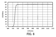
- FIG. 6 is a transmission spectrum of the optical filter according to Example 4.
- FIG. 7 is a transmission spectrum of the optical filter according to Example 5.
- FIG. 8 is a transmission spectrum of the optical filter according to Example 6.
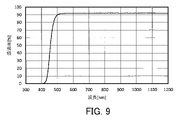
- FIG. 9 is a transmission spectrum of the optical filter according to Example 7.
- FIG. 10 is a transmission spectrum of the optical filter according to Example 8.
- FIG. 11 is a transmission spectrum of the optical filter according to Example 9.
- FIG. 12 is a transmission spectrum of the optical filter according to Example 10.
- FIG. 13 is a transmission spectrum of the optical filter according to Example 11.
- FIG. 14 is a transmission spectrum of the optical filter according to Example 12.
- FIG. 15 is a transmission spectrum of the optical filter according to Example 13.
- FIG. 16 is a transmission spectrum of the optical filter according to Example 14.
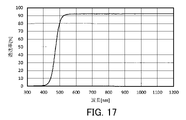
- FIG. 17 is a transmission spectrum of the optical filter according to Example 15.
- FIG. 18 is a transmission spectrum of the optical filter according to Example 16.
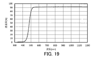
- FIG. 19 is a transmission spectrum of the optical filter according to Example 17.
- FIG. 20 is a transmission spectrum of the optical filter according to Example 18.
- FIG. 21 is a transmission spectrum of the optical filter according to Example 19.
- FIG. 22 is a transmission spectrum of the optical filter according to Example 20.
- FIG. 23 is a transmission spectrum of the optical filter according to Comparative Example 1.
- FIG. 24 is a transmission spectrum of an optical filter according to Comparative Example 2.
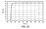
- FIG. 25 is a transmission spectrum of an optical filter according to Comparative Example 3.
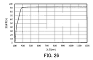
- FIG. 26 is a transmission spectrum of an optical filter according to Comparative Example 4.
- FIG. 27 is a transmission spectrum of an optical filter according to Comparative Example 5.
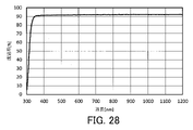
- FIG. FIG. 28 is a transmission spectrum of a transparent glass substrate. 29 is a transmission spectrum of the optical filter according to Example 21.
- FIG. 30 is a reflection spectrum of the optical filter according to Example 21.
- FIG. FIG. 31 is a transmission spectrum of the optical filter according to Example 21 in a high temperature and high humidity test.
- FIG. 32 is a transmission spectrum of the optical filter according to Example 21 in a heat cycle test.
- 33 is a transmission spectrum of the optical filter according to Example 23.
- FIG. 34 is a transmission spectrum of the optical filter according to Example 24.
- FIG. 35 is a transmission spectrum of the optical filter according to Example 26.
- FIG. 36 is a transmission spectrum of the optical filter according to Example 32.
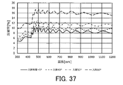
- FIG. 37 is a reflection spectrum of the optical filter according to Example 23.
- FIG. 38 is a reflection spectrum of the optical filter according to Example 24.
- FIG. 39 is a reflection spectrum of the optical filter according to Example 26.
- FIG. 40 is a reflection spectrum of the optical filter according to Example 32.
- FIG. 41 is a transmission spectrum of the optical filter according to Example 36.
- FIG. 42 is a reflection spectrum of the optical filter according to Example 36.
- FIG. 43 is a reflection spectrum of the optical filter according to Example 38.
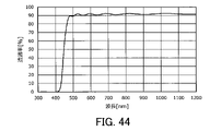
- FIG. 44 is a transmission spectrum of the optical filter according to Example 41.
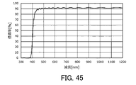
- FIG. 45
- an optical filter for an imaging device using a solid-state imaging device can effectively absorb light in the short wavelength range around 400 nm, the value of the optical filter will be further increased from the viewpoint of reproduction of human visual sensitivity. can be done.
- the wavelength at which the spectral transmittance is 50% in the wavelength range of 350 nm to 450 nm is less than 400 nm.
- the wavelength range at which the spectral transmittance is 50% in the wavelength range of 350 nm to 450 nm is approximately 390 nm to 415 nm.
- the optical filters described in Patent Documents 1 and 2 are advantageous from the viewpoint of effectively absorbing light in the short wavelength region around 400 nm.
- the violet light vertical cut-off filter described in Patent Document 3 may be able to effectively absorb light in the short wavelength region around the wavelength of 400 nm, but the transmittance of visible light around the wavelength of 500 to 650 nm of the filter is considered low.
- the present inventors have made extensive studies to develop a light-absorbing composition that is advantageous from the viewpoint of reproduction of human visibility, particularly effective absorption of light in the short wavelength region around 400 nm.
- the present inventors found that a light-absorbing composition containing a predetermined ultraviolet absorber and a metal component is advantageous from the viewpoint of effectively absorbing light in the short wavelength region.
- the inventors have newly discovered that and completed the present invention.
- the light-absorbing composition according to the present invention contains an ultraviolet absorber having a hydroxy group and a carbonyl group in its molecule, and a metal component. Additionally, at least a portion of the metal component is attached to the organic oxy group. Typically, at least a portion of the metal component is bonded to the oxygen atoms in the organooxy group.
- the light-absorbing film or optical filter produced using the light-absorbing composition tends to effectively absorb light in the wavelength region near the wavelength of 400 nm, which is advantageous from the viewpoint of reproduction of human visibility. .
- UV absorber Advantageous conditions for the UV absorber are that the absorption range and transmission range of light are appropriate, that it is photochemically stable, that the photosensitizing action is low enough to have no effect within the range of use, and that it is thermochemically stable. conditions such as being stable to From this point of view, it is conceivable to utilize a hydrogen transfer reaction (intramolecular hydrogen abstraction reaction) of a hydroxy group in a molecule due to photoexcitation as a mechanism of light absorption by an ultraviolet absorber. UV absorbers that exhibit such mechanisms include, for example, compounds such as hydroxybenzophenones, salicylic acid, hydroxyphenylbenzotriazoles, hydroxyphenyltriazines, and substituted acrylonitriles.
- such a light absorption film is advantageous in effectively and appropriately absorbing light having a wavelength of around 400 nm.
- the phenomenon that the maximum absorption wavelength shifts to the long wavelength side within the wavelength range of 300 nm to 500 nm of the transmission spectrum, or the wavelength at which the transmittance is 50% (UV A phenomenon in which the cut-off wavelength) shifts to the longer wavelength side may occur.
- the absorption characteristic inherent in the ultraviolet absorber is It is adjusted so that light in the short wavelength region can be effectively absorbed.
- the spectral transmittance of such a light absorption film or optical filter tends to be more suitable for use with a solid-state imaging device or the like.
- the metal component is bonded to the organic oxy group, typically in the form of MOR.
- R represents a given organic group, such as an alkyl group, an aryl group, and a vinyl group.
- the arrangement of the hydroxy group and the carbonyl group in the ultraviolet absorber is not limited to a specific arrangement.
- the hydroxy group and the carbonyl group are preferably arranged with 1 to 3 atoms separated from each other. It is believed that this makes it easier for hydrogen to move between the hydroxy group and the carbonyl group in the ultraviolet absorber. For this reason, a phenomenon in which the light absorption band at wavelengths of 300 to 500 nm shifts to the long wavelength side is likely to occur effectively. As a result, the light-absorbing film obtained by curing the light-absorbing composition more reliably tends to effectively and appropriately absorb light having a wavelength of around 400 nm.
- the transmittance T 400 at a wavelength of 400 nm in the transmission spectrum at an incident angle of 0 degrees of the light absorbing film obtained by curing the light absorbing composition according to the present invention is, for example, 10% or less.
- the light-absorbing film obtained by curing the light-absorbing composition more reliably tends to effectively and appropriately absorb light having a wavelength of around 400 nm.
- the transmittance T 400 is preferably 3% or less, more preferably 1% or less.
- the UV absorber is not limited to a specific UV absorber as long as it has a hydroxy group and a carbonyl group in its molecule.
- the UV absorber is desirably a compound that does not readily aggregate when mixed with the metal component.
- the ultraviolet absorber desirably contains a benzophenone compound represented by the following formula (A1).
- A1 a benzophenone compound represented by the following formula (A1).
- the light-absorbing film or optical filter produced using the light-absorbing composition tends to more reliably and effectively absorb light in the short wavelength range around 400 nm.
- R 11 , R 12 , R 21 and R 22 are a hydroxy group.
- R 11 , R 12 , R 21 , or R 22 is a functional group other than a hydroxy group, multiple R 11 , multiple R 12 , multiple R 21 , or multiple R 22 are It may be present and at least one of R 11 , R 12 , R 21 and R 22 may be absent.
- R 11 , R 12 , R 21 or R 22 is a functional group other than a hydroxy group
- the functional group is, for example, a carboxyl group, an aldehyde group, a halogen atom, an alkyl group having 1 to 12 carbon atoms.
- an alkyl group having 1 to 12 carbon atoms in which one or more hydrogen atoms are replaced by halogen atoms, an alkoxy group having 1 to 12 carbon atoms, or one or more hydrogen atoms replaced by halogen atoms is an alkoxy group having 1 to 12 carbon atoms.
- the ultraviolet absorber more desirably contains a benzophenone compound represented by the following formula (A2).
- A2 a benzophenone compound represented by the following formula (A2).
- the light-absorbing film or optical filter produced using the light-absorbing composition more reliably tends to effectively absorb light in the short wavelength range around 400 nm.
- R 31 is a hydrogen atom, a hydroxy group, a carboxyl group, an aldehyde group, a halogen atom, a halogen atom-containing group, an alkyl group having 1 to 12 carbon atoms, or 1 to 12 carbon atoms. is an alkoxy group with atoms.
- R 41 and R 42 are a hydroxy group, a carboxyl group, an aldehyde group, a group having a halogen atom, an alkyl group having 1 to 12 carbon atoms, or an aryl group having 6 to 12 carbon atoms. or an alkoxy group having 1 to 12 carbon atoms, and R 41 and R 42 may be absent.
- a plurality of R 41 may exist, and a plurality of R 42 may exist.
- the group having a halogen atom may be a halogenated alkyl group in which at least one hydrogen atom in the alkyl group is substituted with a halogen atom.
- the group having a halogen atom may be a halogenated aryl group in which at least one hydrogen atom in the aryl group is substituted with a halogen atom.
- the group having a halogen atom may be a halogenated alkoxy group in which at least one hydrogen atom in the alkoxy group is substituted with a halogen atom.
- the benzophenone-based compound represented by formula (A1) or formula (A2) is not limited to a specific compound.
- the benzophenone compounds include, for example, 2,2'-dihydroxy-4,4'-dimethoxybenzophenone, 2,2',4,4'-tetrahydroxybenzophenone, 2-hydroxy-4-methoxybenzophenone, 2-hydroxy- 4-methoxy-4'-chlorobenzophenone, 2-hydroxy-4-n-octoxybenzophenone, 2-hydroxy-4-dodecyloxybenzophenone, 2,4-dihydroxybenzophenone, 2-hydroxy-4-methoxy-2'- the group consisting of carboxybenzophenone, 2,2'-dihydroxy-4-methoxybenzophenone, 2,2'-dihydroxy-4-n-octoxybenzophenone, 2-hydroxy-5-chlorobenzophenone, and 2,4-dibenzoylresorcin; is at least one selected from
- the ultraviolet absorber may contain a salicylic acid-based compound represented by the following formula (B).
- B a salicylic acid-based compound represented by the following formula (B).
- the light-absorbing film or optical filter produced using the light-absorbing composition tends to more reliably and effectively absorb light in the short wavelength range around 400 nm.
- R 51 is a hydroxy group, a carboxy group, a group containing a halogen atom, an alkyl group having 1 to 12 carbon atoms, an aryl group having 6 to 12 carbon atoms, or 1 to 12 It can also be an alkoxy group having 1 carbon atom. In formula (B), multiple R 51 may be present, or R 51 may be absent.
- R 52 is a hydrogen atom, an aryl group, or a halogenated aryl group in which one or more hydrogen atoms are substituted with halogen atoms.
- the group having a halogen atom may be a halogenated alkyl group in which at least one hydrogen atom in the alkyl group is substituted with a halogen atom.
- the group having a halogen atom may be a halogenated aryl group in which at least one hydrogen atom in the aryl group is substituted with a halogen atom.
- the group having a halogen atom may be a halogenated alkoxy group in which at least one hydrogen atom in the alkoxy group is substituted with a halogen atom.
- the salicylic acid compound represented by formula (B) is not limited to a specific compound.
- the salicylic acid-based compound represented by formula (B) includes, for example, at least one selected from the group consisting of phenyl salicylate, 4-butylphenyl salicylate, and octylphenyl salicylate.
- the metal component is not limited to a specific metal component.
- the metal component is typically a thermally and chemically stable component that does not aggregate in the light-absorbing composition and the light-absorbing film made using the light-absorbing composition. Additionally, the metal component is typically a component capable of interacting with the UV absorbers described above.
- the light-absorbing composition may contain a predetermined compound containing a metal component.
- the compound is, for example, a complex.
- the light absorbing composition desirably contains an alkoxide containing a metal component.
- Metal components include, for example, Li, Na, Mg, Ca, Sr, Ba, Ge, Sn, Pb, Al, Ga, In, Tl, Zn, Cd, Cu, Ag, Au, Ni, Pd, Pt, Co, At least one selected from the group consisting of Rh, Ir, Fe, Mn, Cr, Mo, W, V, Nb, Ta, Ti, and Zr. In this case, the metal component tends to interact with the UV absorber.
- the content of the ultraviolet absorbent in the light-absorbing composition is not limited to a specific value. Its content is, for example, 0.05 to 10%, preferably 0.1 to 8%, more preferably 0.2 to 6%, based on mass. The content may be 3% or less, 2% or less, or 1% or less.
- the content of the metal component in the light-absorbing composition is not limited to a specific value. Its content is, for example, 0.005 to 5%, preferably 0.01 to 3%, more preferably 0.02 to 2%, based on mass.
- the ratio of the content of the ultraviolet absorber to the content of the metal component is not limited to a specific value.
- the ratio is, for example, 0.05 to 300, preferably 0.07 to 280, more preferably 0.1 to 260, based on mass.
- the ratio may be 240 or less, 200 or less, 150 or less, 100 or less, 50 or less, or 40 It may be less than or equal to 30 or less.
- the molar ratio of the content of the ultraviolet absorber to the content of the metal component is not limited to a specific value either.
- the molar ratio is, for example, 0.001-40, preferably 0.005-35, more preferably 0.01-30.
- the molar ratio may be 25 or less, 20 or less, 15 or less, 10 or less, 5 or less, or 3 or less. good too.
- the light absorbing film or optical filter produced using the light absorbing composition can more reliably and effectively absorb light in the short wavelength range around 400 nm.
- the light-absorbing composition may further contain a curable resin.
- a light absorbing film containing an ultraviolet absorber and a metal component can be formed by curing the resin in the light absorbing composition.
- an article having a substrate having desired light-absorbing properties can be produced.
- the curable resin is not limited to a specific resin.
- Curable resins are, for example, acrylic resins, epoxy resins, polycarbonate resins, polyether resins, polyester resins, cyclic olefin resins, silicone resins, or polyvinyl acetal (PVA) resins.
- the resin is desirably a silicone resin.
- the resin is more preferably a silicone resin containing aryl groups such as phenyl groups. If the resin contained in the light-absorbing film is hard (rigid), cracks tend to occur due to curing shrinkage during fabrication of the light-absorbing film as the thickness of the layer containing the resin increases.
- the resin is a silicone resin containing an aryl group, the light-absorbing film formed from the light-absorbing composition tends to have good crack resistance.
- silicone resins containing aryl groups tend to have high compatibility or dispersibility with metal components and UV absorbers, and these components are less likely to aggregate.
- silicone resins include KR-255, KR-300, KR-2621-1, KR-211, KR-311, KR-216, KR-212, KR-251, and KR-5230. can. All of these are silicone resins manufactured by Shin-Etsu Chemical Co., Ltd. Silicone resins tend to have high heat resistance. Since the light-absorbing composition contains a silicone resin, it can be expected that the light-absorbing film obtained using the light-absorbing composition also contains the silicone resin and has heat resistance. From this point of view as well, it is advantageous for the light-absorbing composition to contain a silicone resin as a curable resin.
- the ratio of the content of the ultraviolet absorber to the solid content of the resin is not limited to a specific value.
- the ratio is, for example, 0.1% to 10%, preferably 0.2% to 5%, more preferably 0.4% to 3%, based on mass. This is advantageous from the viewpoint of suppressing problems such as degradation of weather resistance and bleeding out.
- the resin may desirably be a PVA resin.
- PVA resin is more desirably polyvinyl butyral (PVB) resin or polyvinyl formal (PVF) resin. These resins are obtained by reacting polyvinyl alcohol with aldehydes.
- PVB and PVF resins contain acetyl and hydroxyl groups attached to vinyl groups as well as butyral or formal groups. These resins can have the advantage of good affinity with metal components due to the contribution of some of the hydroxyl groups contained therein.
- PVB resin and PVF resin can contain a relatively large amount of ultraviolet absorber, and the cured resin composition tends to have high flexibility and durability.
- PVB resins are S-Lec KS-1, KS-3, KS-5, KX-1, BL-1, BL-S, and BX-L. All of these are PVA resins (PVB resins) manufactured by Sekisui Chemical Co., Ltd., and S-LEC is a registered trademark. Further examples of PVB resins are Mobital B20H, B30T, B30H, and B45H. All of these are PVA resins (PVB resins) manufactured by Kuraray Co., Ltd. Mobital is a registered trademark. Specific examples of PVF resins are Vinylec K and Vinylec H. Both of these are PVA resins (PVF resins) manufactured by JNC Corporation, and Vinylec is a registered trademark.
- the light-absorbing composition contains the PVA resin
- the light-absorbing film obtained by using the light-absorbing composition also contains the PVA resin and tends to have flexibility and durability.
- PVB resin has been used extensively as an interlayer film for automobile window shields, and is expected to have high transparency and non-yellowing properties.
- PVB resin and PVF resin are often available in powder form.
- PVB resins and PVF resins are contained in liquid resin compositions by, for example, (I) alcoholic solvents such as methanol, ethanol, n-propanol, isopropanol, and n-butanol, (II) toluene, cyclopenta Aromatic solvents such as non and xylene, (III) ketone solvents such as methyl ethyl ketone (MEK), methyl butyl ketone (MBK), and ethyl acetate, (IV) ethyl acetate, n-propyl acetate, isopropyl acetate, and Used by dissolving an appropriate amount in an ester solvent such as isobutyl acetate, (V) a glycol ester organic solvent such as propylene glycol monomethyl ether acetate, or (VI) a glycol ether organic solvent such
- the organic solvent is preferably an aromatic organic solvent, an alcoholic organic solvent, or a mixture thereof, more preferably an aromatic solvent, because the resin solution has excellent transparency and is stable over time. It is a mixture of organic solvent and alcohol organic solvent.
- the aromatic organic solvent is preferably toluene
- the alcoholic organic solvent is preferably ethanol or propanol, more preferably ethanol.
- the light-absorbing composition it is advantageous for the light-absorbing composition to contain an ultraviolet absorber having a hydroxy group and a carbonyl group in the molecule, a metal component, and a PVA resin from the viewpoint of suppressing bleeding out of the ultraviolet absorber.
- the ultraviolet absorber may powder or float on the surface of the light-absorbing film or optical film depending on the usage environment and the conditions of the method of manufacturing the light-absorbing film. can occur.
- the light-absorbing composition or light-absorbing film contains an ultraviolet absorber having a hydroxy group and a carbonyl group in the molecule, a metal component, and a PVA resin
- the ultraviolet absorption partly combined with the metal component by complexation or the like The agent becomes more likely to bond with some of the hydroxyl groups of the PVA resin via the metal component. Therefore, the ultraviolet absorber is relatively strongly held inside the resin matrix, and the bleeding out of the ultraviolet absorber is easily suppressed.
- a light-absorbing composition can be prepared by mixing and stirring a solution of an ultraviolet absorber and a liquid composition containing a metal component in predetermined amounts.
- the light-absorbing composition may be a liquid composition containing PVB resin.
- the liquid composition usually contains a solvent that dissolves or disperses the PVB in the liquid.
- the solvent is not limited to a specific solvent, but when selecting a solvent for dissolving PVB, an organic solvent can be used as the solvent in consideration of the solubility of PVB.
- the concentration of PVB in the liquid composition is not limited to any particular value. The concentration is appropriately set in consideration of the solubility of PVB in the solvent. Its concentration is, for example, about 10 to 50% by mass.
- a light-absorbing composition can be used to provide, for example, the light-absorbing film 10 shown in FIG.
- the light absorbing film 10 is obtained, for example, by curing a coating film of a light absorbing composition.
- the light absorption film 10 contains an ultraviolet absorber having a hydroxyl group and a carbonyl group in its molecule, and a metal component. At least part of the metal component in the light absorption film 10 is bonded to the organic oxy group. At least a portion of the metal component is bonded to the oxygen atoms in the organic oxy group.
- the light absorption film 10 can effectively absorb light in the short wavelength range around 400 nm.
- the metal component is bonded to the organic oxy group, typically in the form of MOR.
- R represents a given organic group, such as an alkyl group, an aryl group, and a vinyl group.
- the hydroxy group and the carbonyl group are arranged with 1 to 3 atoms separated from each other. This makes it easier for the light absorption film 10 to more reliably and effectively and appropriately absorb light having a wavelength of about 400 nm.
- the ultraviolet absorber in the light absorbing film 10 includes, for example, the benzophenone-based compound represented by formula (A1) above. As a result, the light absorbing film 10 can more reliably and effectively absorb light in the short wavelength range around 400 nm.
- the ultraviolet absorber in the light absorbing film 10 desirably contains the benzophenone-based compound represented by the above formula (A2). As a result, the light absorbing film 10 can more reliably and effectively absorb light in the short wavelength range around 400 nm.
- the ultraviolet absorber in the light absorbing film 10 contains, for example, the salicylic acid-based compound represented by formula (B) above. As a result, the light absorbing film 10 can more reliably and effectively absorb light in the short wavelength range around 400 nm.
- the light absorbing film 10 contains, for example, an alkoxide containing a metal component.
- Metal components in the light absorption film 10 include, for example, Li, Na, Mg, Ca, Sr, Ba, Ge, Sn, Pb, Al, Ga, In, Tl, Zn, Cd, Cu, Ag, Au, Ni, Pd , Pt, Co, Rh, Ir, Fe, Mn, Cr, Mo, W, V, Nb, Ta, Ti, and Zr.
- the content of the ultraviolet absorbent in the light absorbing film 10 is not limited to a specific value. Its content is, for example, 0.1% to 10%, preferably 0.2% to 5%, more preferably 0.4% to 3%, based on mass.
- the content of the metal component in the light absorbing film 10 is not limited to a specific value. Its content is, for example, 0.02% to 5%, preferably 0.04% to 4%, more preferably 0.06% to 3.5%, based on mass.
- the thickness of the light absorption film 10 is not limited to a specific value.
- the thickness of the light absorbing film 10 is, for example, 10 ⁇ m to 600 ⁇ m, may be 10 ⁇ m to 400 ⁇ m, or may be 10 ⁇ m to 300 ⁇ m.
- the transmittance T 400 at a wavelength of 400 nm is, for example, 5% or less.
- the method of curing the light-absorbing composition is not limited to a specific method.
- the light-absorbing composition may be cured by heating at a given temperature.
- the predetermined temperature is not limited to a specific temperature as long as the light absorbing composition can be cured.
- the predetermined temperature is, for example, 85°C or higher, preferably 120°C or higher, more preferably 140°C or higher, and still more preferably 150 to 160°C. This makes it easy for the light absorption film 10 to have good heat resistance while preventing deterioration of the ultraviolet absorber.
- the transmittance T 400 is preferably 3% or less, more preferably 1% or less.
- optical filters 1a and 1b with a light absorbing film 10 can be provided.
- the optical filters 1a and 1b tend to effectively absorb light in the short wavelength range around 400 nm.
- the maximum transmittance T M 300-380 within the wavelength range of 300 to 380 nm is, for example, 3% or less. This makes it easy for the optical filter to effectively absorb light in the short wavelength range around 400 nm.
- the maximum transmittance T M 300-380 is preferably 2% or less, more preferably 1% or less.
- the wavelength at which the transmittance in the wavelength range of 300 to 520 nm is 50% is defined as the UV cutoff wavelength ⁇ UV .
- the condition 405 nm ⁇ UV ⁇ 500 nm is fulfilled. This makes it easy for the light absorption film 10 to effectively absorb light in the short wavelength range around 400 nm.
- the optical filters 1a and 1b preferably satisfy the condition of 405 nm ⁇ UV ⁇ 490 nm, and more preferably satisfy the condition of 405 nm ⁇ UV ⁇ 480 nm.
- the average transmittance T A 550-570 in the wavelength range of 550 to 570 nm is, for example, 87% or more.
- the optical filters 1a and 1b can appropriately transmit visible light, which is advantageous from the viewpoint of reproduction of human visibility.
- the average transmittance T A 550-570 is preferably 88% or more, more preferably 90% or more.
- the transmission spectra obtained by making light in the wavelength range of 300 nm to 1200 nm incident on the optical filters 1a and 1b at an incident angle of 0° are as follows (ia), (ii-a), (iii-a), (iv -a), (va), and (vi-a) requirements may be met.
- the maximum transmittance T M 300-380 in the wavelength range of 300 nm to 380 nm is 3% or less.
- the transmittance T 400 at a wavelength of 400 nm is 5% or less.
- the transmittance T 410 at a wavelength of 410 nm is 10% or less.
- the wavelength ⁇ UV [nm] at which the transmittance is 50% exists within the range of 405 nm to 490 nm.
- the average transmittance T A 550-570 at wavelengths of 550 nm to 570 nm is 87% or more.
- the ratio T 0 UV+ /T 0 UV- of the transmittance T 0 UV+ at the wavelength ( ⁇ UV +10) nm to the transmittance T 0 UV- at the wavelength ( ⁇ UV ⁇ 10) nm is 1.8 or more. is.
- the optical filters 1a and 1b can exhibit high ultraviolet absorbability.
- the maximum value T M 300-380 is more preferably 2% or less, still more preferably 1% or less, particularly preferably 0.5% or less, and most preferably 0.3% or less.
- the optical filters 1a and 1b can exhibit higher ultraviolet absorption.
- the optical filters 1a and 1b can be adapted to optical filter applications that require higher ultraviolet absorption performance.
- the transmittance T 400 is preferably 4% or less, more preferably 3% or less, and even more preferably 1% or less.
- the transmittance T 410 is preferably 9% or less, more preferably 8% or less, still more preferably 6% or less, particularly preferably 3% or less, and most preferably 1% or less.
- the optical filters 1a and 1b can exhibit high ultraviolet absorbability, and the spectrum sensed by the imaging element can more easily match the spectrum corresponding to human visual sensitivity.
- the wavelength ⁇ UV is preferably between 420 nm and 490 nm, more preferably between 420 nm and 450 nm.
- purple fringing tends to be suppressed in the resulting image.
- the purple fringing is color fringing that exhibits a substantially purple color that appears especially on the outline of a subject.
- the transmittance of light belonging to the human visible light range can be increased, making it easier to obtain bright images.
- the transmittance of light belonging to the human visible light range is likely to be high, and bright images are likely to be obtained.
- the transmittance in the wavelength region corresponding to the maximum sensitivity in the human visibility curve tends to be high, and when the human observes the image, he/she tends to perceive the brightness more easily.
- the average T A 550-570 is preferably 88% or more, more preferably 90% or more.
- the ratio T 0 UV+ /T 0 UV- is preferably 1.9 or more, more preferably 2.0 or more, still more preferably 2.2 or more, and particularly preferably 2.4 or more.
- Reflection spectra obtained by making light with a wavelength range of 300 nm to 1200 nm incident on the optical filters 1a and 1b at an incident angle of 5° may satisfy the following requirements (ib) and (ii-b).
- the reflection spectrum obtained by making light with a wavelength range of 300 nm to 1200 nm incident on the optical filters 1a and 1b at an incident angle of 40° satisfies the following requirements (iii-b) and (iv-b).
- the reflection spectrum obtained by making light with a wavelength range of 300 nm to 1200 nm incident on the optical filters 1a and 1b at an incident angle of 60° satisfies the following requirements (vb) and (vi-b) good.
- the maximum reflectance R 5 300-450 in the wavelength range of 300 nm to 450 nm is 20% or less.
- the maximum reflectance R 5 300-600 in the wavelength range of 300 nm to 600 nm is 25% or less.
- the maximum reflectance R 40 300-450 in the wavelength range of 300 nm to 450 nm is 20% or less.
- the maximum reflectance R 40 300-600 in the wavelength range of 300 nm to 600 nm is 25% or less.
- the maximum value of reflectance R 60 300-450 in the wavelength range of 300 nm to 450 nm is 30% or less.
- the maximum reflectance R 60 300-600 in the wavelength range of 300 nm to 600 nm is 35% or less.
- the maximum value of R 5 300-450 is preferably 15% or less.
- the maximum value of R 40 300-450 is preferably 15% or less.
- the maximum value of R 60 300-450 is preferably less than 20%.
- the maximum value of R 5 300-600 is preferably less than 20%.
- the maximum value of R 40 300-600 is preferably less than 20%.
- the maximum value of R 60 300-600 is preferably 25% or less.
- Optical filters 1a and 1b may satisfy requirements (ic), (ii-c), (iii-c), (iv-c), and (vc) below.
- ⁇ 30 UV [nm] in (ic) is the transmittance of 50 in the wavelength range of 350 nm to 500 nm in the transmission spectrum when light in the wavelength range of 300 nm to 1200 nm is incident on the optical filter at an incident angle of 30°. %.
- ⁇ 40 UV [nm] in (ii-c) is the transmittance within the wavelength range of 350 nm to 500 nm in the transmission spectrum when light in the wavelength range of 300 nm to 1200 nm is incident on the optical filter at an incident angle of 40°. is the wavelength at which is 50%.
- ⁇ 50 UV [nm] in (iii-c) is the transmittance within the wavelength range of 350 nm to 500 nm in the transmission spectrum when light in the wavelength range of 300 nm to 1200 nm is incident on the optical filter at an incident angle of 50°. is the wavelength at which is 50%.
- ⁇ 60 UV [nm] in (iv-c) is the transmittance within the wavelength range of 350 nm to 500 nm in the transmission spectrum when light with a wavelength range of 300 nm to 1200 nm is incident on the optical filter at an incident angle of 60°. is the wavelength at which is 50%.
- ⁇ 70 UV [nm] of (vc) is the transmittance of 50 in the wavelength range of 350 nm to 500 nm in the transmission spectrum when light in the wavelength range of 300 nm to 1200 nm is incident on the optical filter at an incident angle of 70 °. %.
- a perfect absorption type UV cut filter can have the advantage that the angle dependence of the transmission spectrum is small.
- a type of UV cut filter that cuts UV rays with a reflective film tends to shift the UV cutoff wavelength to the short wavelength side with respect to obliquely incident light. Therefore, there is a possibility that the ultraviolet rays to be cut may be detected by the sensor depending on the incident angle.
- the optical filters 1a and 1b satisfy the above requirements (i-c) to (v-c), have little change in the UV cutoff wavelength against oblique incidence, and have a short wavelength side of the UV cutoff wavelength. Hard to shift. Therefore, according to the optical filters 1a and 1b, in addition to the function of suppressing ghosts and flares, it is easy to achieve good color reproducibility in which in-plane color unevenness is less likely to occur, and high-quality images can be easily obtained.
- is preferably
- is preferably
- the optical filters 1a and 1b may satisfy the following requirements (id), (ii-d) and (iii-d).
- T m 480-600 is the minimum value of transmittance at wavelengths 480 nm to 600 nm of the transmission spectrum at an incident angle of 0° of the optical filter before the start of the high temperature, high humidity test and heat cycle test.
- a high temperature and high humidity test is performed under the conditions of a temperature of 85°C and a relative humidity of 85%.
- ⁇ DH-240 UV [nm] is the transmittance within the wavelength range of 350 nm to 500 nm in the transmission spectrum of the optical filter at an incident angle of 0° after 240 hours from the start of the high temperature and high humidity test.
- T DH-240 480-600 is the minimum value of transmittance in the wavelength range of 480 nm to 600 nm of its transmission spectrum.
- ⁇ DH-480 UV [nm] is the transmission within the wavelength range of 350 nm to 500 nm in the transmission spectrum of the optical filter at an incident angle of 0° after 480 hours from the start of the high temperature and high humidity test.
- T DH-480 480-600 is the minimum value of transmittance at wavelengths 480 nm to 600 nm of the transmittance spectrum.
- ⁇ DH-1K UV [nm] is the transmission within the wavelength range of 350 nm to 500 nm in the transmission spectrum of the optical filter at an incident angle of 0° after 1008 hours from the start of the high temperature and high humidity test.
- T DH-1K 480-600 is the minimum value of transmittance at wavelengths 480 nm to 600 nm of the transmittance spectrum.
- the optical filters 1a and 1b satisfy the requirements (i-d), (ii-d), and (iii-d), the optical filters 1a and 1b exhibit high UV absorption even in a high-temperature, high-humidity environment.
- the spectrum sensed by the imaging element is more likely to match the spectrum corresponding to human visual sensitivity.
- the transmittance of light belonging to the human visible light range tends to increase, and a bright image can be easily obtained.
- Optical filters 1a and 1b may satisfy requirements (ie), (ii-e), and (iii-e) below.
- T m 480-600 is the minimum value of transmittance at wavelengths 480 nm to 600 nm of the transmission spectrum at an incident angle of 0° of the optical filter before the start of the high temperature, high humidity test and heat cycle test.
- the environmental temperature is maintained at 85°C for 30 minutes, the environmental temperature is changed from 85°C to -40°C over 5 minutes, the environmental temperature is maintained at -40°C for 30 minutes, and the environmental The test involves changing the temperature from -40°C to 85°C over 5 minutes in this order as one cycle.
- ⁇ HC-144 UV [nm] has a transmittance of 50% within the wavelength range of 350 nm to 500 nm of the transmission spectrum at an incident angle of 0° of the optical filter after 144 cycles in the heat cycle test. and T HC-144 480-600 is the minimum value of transmittance between wavelengths 480 nm and 600 nm in the transmission spectrum.
- ⁇ HC-576 UV [nm] has a transmittance of 50% in the wavelength range of 350 nm to 500 nm of the transmission spectrum at an incident angle of 0 ° of the optical filter after 576 cycles in the heat cycle test.
- T HC-576 480-600 is the minimum value of transmittance at wavelengths 480 nm to 600 nm in the transmission spectrum.
- ⁇ HC-1K UV [nm] has a transmittance of 50% in the wavelength range of 350 nm to 500 nm of the transmission spectrum at an incident angle of 0 ° of the optical filter after 1008 cycles in the heat cycle test.
- T HC-1K 480-600 is the minimum value of transmittance at wavelengths 480 nm to 600 nm in the transmission spectrum.
- the optical filters 1a and 1b satisfy the requirements (i-e), (ii-e), and (iii-e), even if the temperature of the environment of the optical filters 1a and 1b changes, the optical filters 1a and 1b In addition, the spectrum sensed by the image pickup device easily matches the spectrum corresponding to human visibility. In addition, even if the temperature of the environment of the optical filters 1a and 1b changes, the transmittance of light belonging to the human visible light range tends to increase, and a bright image can easily be obtained.
- the optical filter 1a is composed of, for example, the light absorption film 10 alone.
- the optical filter 1a can be used separately from, for example, an imaging device or an optical component.
- the optical filter 1a may be bonded to the imaging element and optical components.
- the optical filter 1a may be configured by applying the above-described light-absorbing composition to an imaging device or an optical component and curing the light-absorbing composition.
- the optical filter 1a can be produced, for example, by peeling off the light absorption film 10 formed on the substrate from the substrate.
- the material of the substrate may be glass, resin, or metal.
- the surface of the substrate may be subjected to surface treatment such as coating using a fluorine-containing compound.
- the optical filter 1b includes a light absorbing film 10 and a transparent dielectric substrate 20.
- the light absorption film 10 is provided parallel to one main surface of the transparent dielectric substrate 20 .
- the light absorbing film 10 may be in contact with one main surface of the transparent dielectric substrate 20, for example.
- the light absorbing film 10 can be formed by applying the above light absorbing composition to one main surface of the transparent dielectric substrate 20 and curing the light absorbing composition.
- the type of transparent dielectric substrate 20 is not limited to a specific type.
- the transparent dielectric substrate 20 may have absorption in the infrared region.
- the transparent dielectric substrate 20 may have an average spectral transmittance of 90% or more at wavelengths of 350 nm to 900 nm, for example.
- the material of the transparent dielectric substrate 20 is not limited to a specific material, but is, for example, predetermined glass or resin. If the material of the transparent dielectric substrate 20 is glass, the transparent dielectric substrate 20 may be, for example, transparent glass made of silicate glass such as soda-lime glass and borosilicate glass, or colored glass such as Cu and Co. It can be a phosphate glass and a fluorophosphate glass containing ingredients.
- Phosphate glass and fluorophosphate glass containing coloring components are, for example, infrared-absorbing glasses, and themselves have light-absorbing properties.
- the light-absorbing film 10 is used together with the transparent dielectric substrate 20 of infrared-absorbing glass, the light absorption and transmission spectra of both can be adjusted to produce an optical filter having desired optical characteristics. High degree of design freedom.
- the resin is, for example, a cyclic olefin resin such as a norbornene resin, a polyarylate resin, an acrylic resin, a modified acrylic resin, a polyimide resin, a polyetherimide resin, or a polysulfone. resin, polyethersulfone resin, polycarbonate resin, or silicone resin.
- Each of the optical filters 1a and 1b may be modified to further include other functional films such as an infrared absorbing film, an infrared reflecting film, and an antireflection film.
- a functional film can be provided on the light absorption film 10 or the transparent dielectric substrate 20.
- FIG. For example, by providing an optical filter with an antireflection film, it is possible to increase the transmittance in a predetermined wavelength range (for example, the visible light range).
- the antireflection coating may be constructed as a layer of low refractive index material such as MgF2 and SiO2 , or a stack of layers of such low refractive index material and layers of high refractive index material such as TiO2 . , or may be configured as a dielectric multilayer film.
- Such an antireflection film can be formed by a method involving physical reaction such as vacuum deposition and sputtering, or a method involving chemical reaction such as CVD method and sol-gel method.
- the optical filter may be configured, for example, in a state in which the light absorbing film 10 is arranged between two sheets of plate-shaped glass. This improves the rigidity and mechanical strength of the optical filter. In addition, the main surface of the optical filter becomes hard, which is advantageous from the viewpoint of scratch prevention and the like. This advantage is particularly important when a relatively flexible resin is used as the binder or matrix in the light absorbing film 10 .
- an optical filter having better optical properties can be provided.
- an optical filter 1c with a light absorption film 10 and an antireflection film 30 can be provided.
- an optical filter with an antireflection film formed thereon when light is incident on the optical filter at a predetermined angle of incidence, the amount of light reflected from the optical filter is reduced and becomes remarkably close to zero. This is because, in an imaging device equipped with an optical filter having an antireflection film formed thereon, for example, from the viewpoint of preventing ghost, flare, and noise generated by multiple scattering of reflected light in the imaging device or camera module. very advantageous.
- the material of the antireflection film is not limited to a specific material.
- the method of forming the antireflection film is not limited to a specific method.
- the method of forming the antireflection film may be a vapor phase method or a liquid phase method.
- the method of forming the antireflection film may be vapor deposition.
- the method of forming the antireflection film may be a sol-gel method using a reactive material containing silicon, and this method is a liquid phase method excellent in forming an antireflection film.
- the antireflection film may be a single-layer film made of the same kind of material or a multilayer film made of two or more different kinds of materials.
- a material constituting each layer of the film and multilayer film is not limited to a specific material.
- the material is, for example, an inorganic compound such as SiO2 , TiO2 , Ta2O3 , MgF2 , Al2O3 , CaF2 , ZrO2 , CeO2 , and ZnS.
- the film or layer may be formed by a so-called sol-gel method using an alkoxysilane compound as a starting material.
- the alkoxysilane compound undergoes hydrolysis and polycondensation in the presence of water and a catalyst to obtain a dense and hard film containing SiO 2 .
- the sol-gel method has the advantage of being able to form films or layers containing SiO 2 without requiring high temperatures.
- the starting material is not limited to a specific material, nor is the functional group of the starting material limited to a specific functional group.
- the starting materials desirably include "trifunctional silanes containing alkyl groups" such as MTES (methyltriethoxysilane) and TEOS (tetraethoxysilane), and "tetrafunctional silanes". Tetrafunctional silane is indispensable for forming a film or layer having a strong and dense skeleton. On the other hand, it is difficult to control the reactivity with only tetrafunctional silane, and it is difficult to adjust the polarity of the film or layer. In addition, cracks are likely to occur in the film or layer.
- the starting material contains trifunctional silane in addition to tetrafunctional silane
- the flexibility of the silica skeleton is improved, the porosity of the film or layer is easily adjusted, and cracks in the film or layer are easily suppressed.
- the organic functional groups in the trifunctional silane are not originally limited to specific functional groups.
- a trifunctional silane having a methyl group as an organic functional group is desirable in order to form a homogeneous liquid and coating film when combined with a tetrafunctional silane.
- Starting materials may include components other than those involved in the sol-gel process. For example, the starting material may contain particulates and fillers for refractive index tuning.
- the fine particles and filler may be hollow or may be a high refractive index material.
- the starting material may contain components that decompose at low temperatures. This makes it easy to adjust the refractive index of the antireflection film.
- the temperature for baking the coating film in the sol-gel method is not limited to a specific temperature. The temperature is, for example, in the range of 60°C to 250°C, preferably in the range of 70°C to 230°C, more preferably in the range of 80°C to 200°C. Since the light absorption film and the optical filter can have high heat resistance, no problem occurs in baking the coating film in the sol-gel method, and a strong antireflection film can be easily formed.
- the material of the single-layer film has a low refractive index.
- n 0 is the refractive index of the substrate for the formation of the antireflection coating.
- the antireflection film contains hollow particles made of metal oxides such as SiO 2 and TiO 2 or organic materials such as PMMA, air having a refractive index of about 1 occupies the interior of the hollow particles. , the refractive index of the antireflection film tends to be low.
- the antireflection coating may contain solid particles formed of the above materials.
- the antireflection film is required to have mechanical strength such as scratch resistance, it is advantageous for the antireflection film to contain such solid particles.
- a film may be formed by a sol-gel method in a state containing such hollow particles or solid particles.
- the SiO 2 in the film formed by the sol-gel method has a good affinity with the hollow particles or solid particles, and the hollow particles or solid particles aggregate. is suppressed, and suppression of bleed out can be expected.
- the antireflection film may have a multilayer structure including a layer containing SiO 2 formed by a sol-gel method and a layer formed by, for example, a vacuum deposition method, a sol-gel method, or another method. .
- a multilayer structure including a layer containing SiO 2 formed by a sol-gel method and a layer formed by, for example, a vacuum deposition method, a sol-gel method, or another method.
- the layer to be combined includes, for example, a layer containing hollow particles and containing SiO2 formed by a sol-gel method. , a layer made of a material having a relatively high refractive index such as TiO 2 and Ta 2 O 3 , or a layer made of another material such as MgF 2 . good.
- the light entrance surface and the light exit surface of the optical filter 1c are formed by an antireflection film 30.
- the optical filter 1c has antireflection films 30 on both sides thereof, for example.
- the antireflection film 30 contains, for example, SiO2 .
- Transmission spectra obtained when light with a wavelength range of 300 nm to 1200 nm is incident on the optical filter 1c at an incident angle of 0° are, for example, the following (if), (ii-f), (iii-f), (iv -f), (vf), (vi-f), and (vii-f).
- the maximum transmittance Tb M 300-380 in the wavelength range of 300 nm to 380 nm is 0.1% or less.
- the transmittance Tb400 at a wavelength of 400 nm is 5% or less.
- the transmittance Tb 410 at a wavelength of 410 nm is 10% or less.
- the minimum transmittance Tb m 480-600 at wavelengths of 480 nm to 600 nm is 92% or more.
- the average transmittance Tb a 550-570 at a wavelength of 550 nm to 570 nm is 90% or more.
- the ratio Tb 0 UV+ /Tb 0 UV- of the transmittance Tb 0 UV+ at the wavelength ( ⁇ b UV +10) nm to the transmittance Tb 0 UV- at the wavelength ( ⁇ b UV -10) nm is 2.5 or more. is.
- a reflection spectrum obtained by making light with a wavelength range of 300 nm to 1200 nm incident on the optical filter 1c at an incident angle of 5° satisfies the following requirements (ig) and (ii-g), for example.
- a reflection spectrum obtained by irradiating the optical filter 1c with light having a wavelength range of 300 nm to 1200 nm at an incident angle of 40° satisfies, for example, the following requirements (iii-g) and (iv-g).
- a reflection spectrum obtained by irradiating the optical filter 1c with light having a wavelength range of 300 nm to 1200 nm at an incident angle of 60° satisfies, for example, the following requirements (vg) and (vi-g).
- the maximum reflectance R 5 300-450 in the wavelength range of 300 nm to 450 nm is 7% or less.
- the maximum reflectance R 5 300-600 in the wavelength range of 300 nm to 600 nm is 9% or less.
- the maximum reflectance R 40 300-450 in the wavelength range of 300 nm to 450 nm is 8% or less.
- the maximum reflectance R 40 300-600 in the wavelength range of 300 nm to 600 nm is 10% or less.
- the maximum reflectance R 60 300-450 in the wavelength range of 300 nm to 450 nm is 12% or less.
- the maximum reflectance R 60 300-600 in the wavelength range of 300 nm to 600 nm is 14% or less.
- UV absorber The following UV absorbers were used in the production of optical filters according to Examples and Comparative Examples.
- the structural formulas of the ultraviolet absorbers (1-i), (1-ii), (1-iii), and (1-iv) are the following formulas (C), (D), (E), and (F).
- Example 1 5.0 g of UV absorber (1-i) and 95.0 g of ethanol were mixed and stirred for 30 minutes to obtain a UV absorber solution according to Example 1. Next, 99.38 g of silicone resin (manufactured by Shin-Etsu Chemical Co., Ltd., product name: KR-300) and 0.62 g of compound (2-i) containing a metal component were mixed and stirred for 30 minutes. A liquid composition containing a metal component was obtained. 2.0 g of the ultraviolet absorbent solution according to Example 1 and 10.0 g of the metal component-containing liquid composition according to Example 1 were mixed and stirred for 30 minutes to obtain a light absorbing composition according to Example 1. rice field.
- Table 3 shows the content of each component in the ultraviolet absorbent solution, the metal component-containing liquid composition, and the light absorbing composition and the mass ratio of the predetermined component.
- the solid content in the silicone resin KR-300 is 50% by mass, and the content of the metal component in the compound (2-i) containing the metal component is 6.5% by mass. The amount of solids in the composition was determined.
- a dispenser was used in a 40 mm x 40 mm area in the center of one main surface of a transparent glass substrate made of borosilicate glass (manufactured by SCHOTT, product name: D263 Teco) having dimensions of 76 mm x 76 mm x 0.21 mm. Then, the light-absorbing composition was applied to form a coating film. After sufficiently drying the obtained coating film at room temperature, it is placed in an oven and heat-treated at 160 ° C. for 1 hour to volatilize the solvent and harden. Example 1 containing an ultraviolet absorber and a metal component was obtained. Thus, an optical filter according to Example 1 having the light absorbing film according to Example 1 was produced. A transmission spectrum of the optical filter according to Example 1 is shown in FIG. Table 5 shows the characteristics related to the wavelength and the transmittance and the thickness of the light absorbing film, which are observed from FIG.
- Example 2 2.0 g of UV absorber (1-ii) and 98.0 g of toluene were mixed and stirred for 30 minutes to obtain a UV absorber solution according to Example 2. Next, 99.38 g of silicone resin (manufactured by Shin-Etsu Chemical Co., Ltd., product name: KR-300) and 0.62 g of compound (2-i) containing a metal component were mixed and stirred for 30 minutes. A liquid composition containing a metal component was obtained. 5.0 g of the ultraviolet absorbent solution according to Example 2 and 10.0 g of the metal component-containing liquid composition according to Example 2 are mixed and stirred for 30 minutes to obtain a light absorbing composition according to Example 2. rice field. Table 3 shows the content of each component in the ultraviolet absorbent solution, the metal component-containing liquid composition, and the light absorbing composition and the mass ratio of the predetermined component.
- Transparent glass was prepared in the same manner as in Example 1, except that the light-absorbing composition according to Example 2 was used instead of the light-absorbing composition according to Example 1 and the heat treatment temperature was set to 120 ° C.
- the coating film of the light-absorbing composition was cured on the substrate to obtain a light-absorbing film according to Example 2.
- an optical filter according to Example 2 having the light absorption film according to Example 2 was produced.
- a transmission spectrum of the optical filter according to Example 2 is shown in FIG. Table 5 shows the characteristics related to the wavelength and the transmittance and the thickness of the light absorbing film observed from FIG.
- Examples 3 and 4 Light-absorbing compositions according to Examples 3 and 4 were prepared in the same manner as in Example 2, except that the amount of the ultraviolet absorber solution added and the amount of the metal component-containing liquid composition added were changed as shown in Table 3. did. In the same manner as in Example 2, except that the light-absorbing compositions according to Examples 3 and 4 were used instead of the light-absorbing composition according to Example 2, each light-absorbing composition was formed on a transparent glass substrate. The coating film of the object was cured to form the light absorbing films according to Examples 3 and 4, and the optical filters according to Examples 3 and 4 were produced. The transmission spectra of the optical filters according to Examples 3 and 4 are shown in FIGS. 5 and 6, respectively. Table 5 shows the characteristics related to the wavelength and transmittance and the thickness of the light absorbing film seen from FIGS.
- Examples 5 to 8 Preparation of an ultraviolet absorber solution, preparation of a metal component-containing liquid composition, and light-absorbing composition were carried out in the same manner as in Example 1, except that the types of components and the contents of components were adjusted as shown in Table 3. was prepared to obtain light-absorbing compositions according to Examples 5-8.
- compound (2-ii) containing a metal component was used for preparing the liquid composition containing a metal component.
- the ultraviolet absorbent (1-i) was used to prepare the ultraviolet absorbent solution
- Examples 7 and 8 the ultraviolet absorbent (1-ii) was used to prepare the ultraviolet absorbent solution.
- the amount of solid content in the light-absorbing composition was determined on the premise that the content of the metal component in the compound (2-ii) containing the metal component was 11.3% by mass.
- each light-absorbing composition was formed on a transparent glass substrate.
- the coating film of the product was cured to form the light absorbing films according to Examples 5 to 8, and the optical filters according to Examples 5 to 8 were produced.
- the transmission spectra of the optical filters according to Examples 5-8 are shown in FIGS. 7-10, respectively.
- Table 5 shows the characteristics related to the wavelength and transmittance and the thickness of the light absorption film observed from FIGS.
- Example 9 to 19 Preparation of an ultraviolet absorber solution, preparation of a metal component-containing liquid composition, and light-absorbing composition were carried out in the same manner as in Example 1, except that the types of components and the contents of components were adjusted as shown in Table 3. was prepared to obtain light-absorbing compositions according to Examples 9-19.
- the UV absorber (1-i) was used to prepare the UV absorber solution
- the UV absorber (1-ii) was used to prepare the UV absorber solution.
- compound (2-iii) containing a metal component was used for preparing the liquid composition containing a metal component.
- the amount of solid content in the light-absorbing composition was determined on the premise that the content of the metal component in the compound (2-iii) containing the metal component was 13.2% by mass.
- each light-absorbing composition was formed on a transparent glass substrate.
- the coating film of the product was cured to form the light absorbing films according to Examples 9 to 19, and the optical filters according to Examples 9 to 19 were produced. Transmission spectra of the optical filters according to Examples 9 to 19 are shown in FIGS. 11 to 21, respectively.
- Table 5 shows the characteristics related to the wavelength and transmittance and the thickness of the light absorption film observed from FIGS.
- Example 20 Light according to Example 20 in the same manner as in Example 1, except that the ultraviolet absorber (1-iii) was used instead of the ultraviolet absorber (1-i) to prepare the ultraviolet absorber solution according to Example 20. An absorbent composition was obtained. In the same manner as in Example 1, except that the light-absorbing composition according to Example 20 was used instead of the light-absorbing composition according to Example 1, a coating film of the light-absorbing composition was formed on a transparent glass substrate. was cured to form a light absorption film according to Example 20, and an optical filter according to Example 20 was produced.
- FIG. 22 shows the transmission spectrum of the optical filter according to Example 20.
- FIG. Table 5 shows the characteristics related to the wavelength and the transmittance and the thickness of the light absorbing film, which are observed from FIG.
- Table 4 shows the content of each component and the mass ratio of predetermined components in the ultraviolet absorbent solution and the light absorbing composition.
- a coating film of a light-absorbing composition was formed on a transparent glass substrate in the same manner as in Example 1, except that the light-absorbing composition according to Comparative Example 3 was used instead of the light-absorbing composition according to Example 1.
- each light-absorbing composition was formed on a transparent glass substrate.
- the coating film of the object was cured to form the light absorbing films according to Comparative Examples 4 and 5, and the optical filters according to Comparative Examples 4 and 5 were produced.
- the transmission spectra of the optical filters according to Comparative Examples 4 and 5 are shown in FIGS. 26 and 27, respectively.
- Table 5 shows the characteristics related to the wavelength and transmittance and the thickness of the light absorption film observed from FIGS.
- the optical filters according to Examples 1 to 20 have a transmittance T 400 of 1% or less at a wavelength of 400 nm, and the optical filters according to Example 1 have good optical properties including sufficient ultraviolet absorption ability. It was confirmed to have In the optical filters according to Examples 1 to 20, the maximum transmittance value T M 300-380 at a wavelength of 300 to 380 nm is 1% or less. T M 300-380 was 0.5% or less, and the T M 300-380 was 0.15% or less in the optical filters according to Examples other than Examples 12-17. In the optical filters according to Examples 1 to 20, the average transmittance T A 550-570 in the wavelength range of 550 to 570 nm was 90% or more.
- FIG. 28 shows the transmission spectrum of the transparent glass substrate used in each example and comparative example. Based on this transmission spectrum, it was suggested that the transmittance T 400 at a wavelength of 400 nm was 5% or less in the light absorption films according to Examples 1 to 20.
- the optical filter according to Example 1 and the optical filter according to Comparative Example 1 are compared.
- T 400 was 55.25%.
- the optical filter of Example 1 has an increased ability to absorb light at wavelengths around 400 nm and longer wavelengths. This suggests that the wavelength band of light absorption shifts to the longer wavelength side due to interaction such as partial formation of a complex between the aluminum component, which is a metal component, and the ultraviolet absorber in the light absorbing film.
- the average value TA 550-570 of the optical filter according to Example 1 was as high as 90% or more. This suggests that the proper inclusion of the UV absorber in the presence of the alkoxy group suppresses scattering due to unevenness on the surface of the light absorbing film due to bleeding out.
- the optical filter according to Example 2 and the optical filter according to Comparative Example 2 are compared.
- T 400 was 36.39%.
- the optical filter of Example 2 has an increased ability to absorb light at wavelengths around 400 nm and longer wavelengths. It is presumed that the same circumstances as the comparison between Example 1 and Comparative Example 1 exist between Example 2 and Comparative Example 2.
- the UV cutoff wavelength ⁇ UV is 441 to 480 nm
- the UV cutoff wavelength ⁇ UV is 450 nm. ⁇ 480 nm.
- the difference between the UV cutoff wavelength ⁇ UV in the optical filter according to Example 1 and the UV cutoff wavelength ⁇ UV in the optical filter according to Comparative Example 1 is 42 nm.
- the difference between the UV cutoff wavelength ⁇ UV in the optical filter according to Example 2 and the UV cutoff wavelength ⁇ UV in the optical filter according to Comparative Example 2 is 41 nm.
- the difference between the UV cutoff wavelength ⁇ UV in the optical filter according to Example 20 and the UV cutoff wavelength ⁇ UV in the optical filter according to Comparative Example 3 is 45 nm.
- the UV cutoff wavelength ⁇ UV in the optical filter according to the present invention satisfies the condition
- ⁇ UV R is the UV cutoff wavelength ⁇ UV of an optical filter produced in the same manner as the optical filter according to the present invention, except that the light-absorbing film does not contain a metal component.
- the optical filter according to the present invention preferably satisfies
- benzophenone-based compounds having a hydroxy group the mechanism of light absorption is understood to be brought about by a resonance structure relating to hydrogen abstraction and acceptance between a carbonyl group and a hydroxy group in one molecule.
- Substances that absorb light by abstraction and acceptance of hydrogen in one molecule include hydroxybenzophenone, salicylic acid, benzotriazole compounds, and triazine compounds.
- Benzotriazole-based compounds and triazine compounds have a hydroxy group, and a hydrogen abstraction and acceptance mechanism occurs with the nitrogen in the molecule.
- an ultraviolet absorbing compound having a hydroxy group and a carbonyl group in one molecule such as hydroxybenzophenone and salicylic acid.
- the use of agents is considered desirable.
- the content of the ultraviolet absorber in the light-absorbing composition is, for example, 0.05% to 3%, preferably 0.1% to 2%, more preferably 0.1% to 2%, based on mass. 0.2% to 1%.
- the content of the metal component in the light-absorbing composition is, for example, 0.005% to 5%, preferably 0.01 to 3%, more preferably 0.02% to 2%, based on mass. be.
- the content of the ultraviolet absorber in the light absorbing film 10 is not limited to a specific value. Its content is, for example, 0.1% to 10%, preferably 0.2% to 5%, more preferably 0.4% to 3%, based on mass.
- the content of the metal component in the light absorbing film 10 is, for example, 0.02% to 5%, preferably 0.04% to 4%, and more preferably 0.06% to 3% by mass. 0.5%.
- Example 21 5.0 g of UV absorber (1-i), 80.0 g of cyclohexanone and 8.0 g of polyvinyl butyral were mixed and stirred for 30 minutes. Next, 0.308 g of compound (2-i) containing a metal component was mixed and stirred for 30 minutes to obtain a light-absorbing composition according to Example 21.
- Tables 1 and 2 show details of the light absorbing agent and the metal component-containing compound.
- Table 7 shows the content of each component and the mass ratio of predetermined components in the light-absorbing composition according to Example 21. On the premise that the content of the metal component in the compound (2-i) containing the metal component is 6.5% by mass as shown in Table 2, the component ratio of the light-absorbing composition according to Example 21 was calculated. rice field.
- a light-absorbing composition according to Example 21 was spin-coated on one main surface of a transparent glass substrate made of borosilicate glass (manufactured by SCHOTT, product name: D263T eco) having dimensions of 76 mm ⁇ 76 mm ⁇ 0.21 mm. was applied to form a coating film. After sufficiently drying the resulting coating film at room temperature, it was placed in an oven and subjected to heat treatment at 140° C. for 1 hour and 160° C. for 2 hours to complete the reaction and obtain a light absorbing film according to Example 21. . Thus, an optical filter having a light absorbing film according to Example 21 was produced.
- FIG. 29 shows transmission spectra of the optical filter according to Example 21 at incident angles of 0°, 30°, 40°, 50°, 60° and 70°.
- FIG. 30 shows reflection spectra of the optical filter according to Example 21 at incident angles of 5°, 40°, 50° and 60°.
- Table 8 shows the characteristics related to wavelength and transmittance and the thickness of the light absorbing film seen from FIG.
- Table 9 shows the incident angle dependence of the transmission spectrum
- Table 10 shows the maximum value of reflectance in the wavelength range of 300 nm to 450 nm and the maximum value of reflectance in the wavelength range of 300 nm to 600 nm for each incident angle of the reflection spectrum.
- a high-temperature and high-humidity test (dump heat test) was performed by placing the optical filter of Example 21 in a constant temperature and humidity test chamber and exposing it to an environment with a temperature of 85° C. and a relative humidity of 85% for 1008 hours.
- a constant temperature and humidity test chamber a constant temperature and humidity apparatus KCL-2000A manufactured by Tokyo Rikakikai Co., Ltd. was used.
- the optical filter was taken out and the transmission spectrum of the optical filter was measured. This measurement was performed at 25° C. with an incident angle of 0°.
- Table 11 shows transmission spectra of the optical filter according to Example 21 before and after the high temperature and high humidity test.
- Table 11 shows
- T The values of DH-480 480-600 - T m 480-600
- the optical filter according to Example 21 which had not been subjected to the high temperature and high humidity test, was allowed to stand still inside a heat cycle tank, and subjected to 1008 cycles of a heat cycle test at 85°C/-40°C.
- the temperature inside the heat cycle bath was maintained at 85° C. and ⁇ 40° C. for 30 minutes, respectively, and the temperature was raised or lowered from one temperature to the other over 5 minutes.
- a thermal shock tester TSA-103ES manufactured by ESPEC was used.
- the optical filter was taken out and the transmission spectrum of the optical filter was measured.
- FIG. 32 shows transmission spectra of the optical filter according to Example 21 before and after the heat cycle test. Measurements were taken at 25° C.
- Table 12 shows
- T The values of HC-576 480-600 - T m 480-600
- Examples 22 to 35 Based on the materials and production conditions shown in Table 1, Table 2 or Table 6, and Table 7, in the same manner as in Example 21, the light-absorbing compositions according to Examples 22 to 35 and Examples 22 to 35 An optical filter having such a light absorption film was produced.
- a transparent glass substrate previously coated with a fluorine compound was used, and after the light absorption film was formed, the light absorption film was peeled off from the transparent glass substrate to obtain an optical filter composed of the light absorption film. .
- transmission spectra were measured at incident angles of 0°, 30°, 40°, 50°, 60°, and 70°.
- 33 to 36 show the transmission spectra of the optical filters according to Examples 23, 24, 26 and 32.
- FIG. Table 8 shows parameters of the optical filters according to Examples 22 to 35, which can be seen from the transmission spectra when the incident angle is 0°.
- Reflection spectra of the optical filters according to Examples 22 to 35 were measured at incident angles of 5°, 40°, 50°, and 60°.
- 37-40 show reflection spectra of the optical filters according to Examples 23, 24, 26 and 32, respectively.
- Table 10 shows the maximum reflectance in the wavelength range of 300 nm to 450 nm and the Indicates the maximum value of reflectance.
- optical filters according to Examples 23, 24, 26, and 32 were subjected to high-temperature, high-humidity tests and heat cycle tests in the same manner as in Example 21.
- Tables 11 and 12 show parameters of the optical filters of Examples 23, 24, 26, and 32, similarly to Example 21.
- Example 36 Both main surfaces of the optical filter of Example 23 were coated with antireflection films to obtain an optical filter of Example 36.
- the anti-reflection coating included a single layer of silicon oxide, such as SiO 2 , formed by a sol-gel method.
- a liquid antireflection film precursor (alkoxysilane-containing composition) containing at least an alkoxysilane compound and water was prepared.
- the alkoxysilane-containing composition contained methyltriethoxysilane (MTES) and tetraethoxysilane (TEOS) in a weight ratio of 4:1. Furthermore, this alkoxysilane-containing composition was prepared by mixing water and ethanol as solvents.
- MTES methyltriethoxysilane
- TEOS tetraethoxysilane
- the alkoxysilane composition was applied on both sides of the optical filter of Example 23 by spin coating.
- One surface of the optical filter was the surface of the light absorbing film, and the other surface of the optical filter was the surface of the transparent glass substrate.
- the alkoxysilane composition first, the alkoxysilane composition was applied to one side and left at room temperature for about 1 minute to temporarily dry the coating film, and then the alkoxysilane composition was applied to the opposite side. Thereafter, a baking treatment was performed at 160° C. for about 1 hour to volatilize and remove excess solvent, and the coating film was cured by hydrolysis and polycondensation reaction of alkoxysilane to obtain an antireflection film.
- an optical filter according to Example 36 was obtained.
- the resulting antireflection film was porous and had a thickness of about 180 nm.
- FIG. 41 shows the transmission spectrum of the optical filter according to Example 36.
- Table 8 shows each parameter that can be seen from the transmission spectrum of the optical filter according to Example 36 when the incident angle is 0°.
- Reflection spectra of the optical filter according to Example 36 were measured at incident angles of 5°, 40°, 50°, and 60°.
- FIG. 42 shows the reflection spectrum of the optical filter.
- Table 10 shows the maximum reflectance in the wavelength range of 300 nm to 450 nm and the maximum reflectance in the wavelength range of 300 nm to 600 nm for each incident angle of the reflection spectrum of the optical filter according to Example 36.
- Examples 37 to 41 Based on the materials and production conditions described in Tables 1, 2, and 7, in the same manner as in Example 21, light absorbing compositions according to Examples 37 to 41 and light absorption according to Examples 37 to 41 An optical filter with a membrane was made. Transmission spectra were measured at angles of incidence of 0°, 30°, 40°, 50°, 60°, and 70° for Examples 37-41. 43 and 44 show the transmission spectra of the optical filters of Examples 38 and 41, respectively.
- Table 8 shows the parameters of the optical filters of Examples 37 to 41 that can be seen from the transmission spectra when the incident angle is 0°.
- ⁇ Comparative Example 6> A light-absorbing composition according to Comparative Example 6 and a light-absorbing film according to Comparative Example 6 were prepared in the same manner as in Example 21 based on the materials and production conditions described in Tables 1, 2, and 7. An optical filter was produced.
- transmission spectra were measured at incident angles of 0°, 30°, 40°, 50°, 60°, and 70°.
- FIG. 45 shows the transmission spectrum of the optical filter of Comparative Example 6.
- Table 8 shows each parameter that can be seen from the transmission spectrum of the optical filter of Comparative Example 6 when the incident angle is 0°.
Landscapes
- Chemical & Material Sciences (AREA)
- Physics & Mathematics (AREA)
- Health & Medical Sciences (AREA)
- Chemical Kinetics & Catalysis (AREA)
- Medicinal Chemistry (AREA)
- Polymers & Plastics (AREA)
- Organic Chemistry (AREA)
- General Physics & Mathematics (AREA)
- Optics & Photonics (AREA)
- Toxicology (AREA)
- Optical Filters (AREA)
Priority Applications (4)
| Application Number | Priority Date | Filing Date | Title |
|---|---|---|---|
| JP2023520929A JPWO2022239590A1 (https=) | 2021-05-14 | 2022-04-11 | |
| KR1020237038095A KR20240008309A (ko) | 2021-05-14 | 2022-04-11 | 광흡수성 조성물, 광흡수막, 광흡수막의 제조 방법, 및 광학 필터 |
| US18/560,772 US20240377565A1 (en) | 2021-05-14 | 2022-04-11 | Light-absorbing composition, light-absorbing film, method for producing light-absorbing film, and optical filter |
| CN202280032223.9A CN117255960A (zh) | 2021-05-14 | 2022-04-11 | 光吸收性组合物、光吸收膜、光吸收膜的制造方法以及滤光器 |
Applications Claiming Priority (2)
| Application Number | Priority Date | Filing Date | Title |
|---|---|---|---|
| JP2021-082619 | 2021-05-14 | ||
| JP2021082619 | 2021-05-14 |
Publications (1)
| Publication Number | Publication Date |
|---|---|
| WO2022239590A1 true WO2022239590A1 (ja) | 2022-11-17 |
Family
ID=84028243
Family Applications (1)
| Application Number | Title | Priority Date | Filing Date |
|---|---|---|---|
| PCT/JP2022/017540 Ceased WO2022239590A1 (ja) | 2021-05-14 | 2022-04-11 | 光吸収性組成物、光吸収膜、光吸収膜の製造方法、及び光学フィルタ |
Country Status (5)
| Country | Link |
|---|---|
| US (1) | US20240377565A1 (https=) |
| JP (1) | JPWO2022239590A1 (https=) |
| KR (1) | KR20240008309A (https=) |
| CN (1) | CN117255960A (https=) |
| WO (1) | WO2022239590A1 (https=) |
Cited By (1)
| Publication number | Priority date | Publication date | Assignee | Title |
|---|---|---|---|---|
| WO2024090311A1 (ja) * | 2022-10-27 | 2024-05-02 | 日本板硝子株式会社 | 光吸収性組成物、光吸収性組成物の製造方法、光吸収膜、光学フィルタ、及び光学フィルタの製造方法 |
Citations (4)
| Publication number | Priority date | Publication date | Assignee | Title |
|---|---|---|---|---|
| JP2003107202A (ja) * | 2001-09-28 | 2003-04-09 | Nof Corp | レンズ用コーティング組成物 |
| WO2020129930A1 (ja) * | 2018-12-17 | 2020-06-25 | 株式会社トクヤマ | 光学材料用硬化性組成物および光学材料 |
| JP2020154320A (ja) * | 2017-07-06 | 2020-09-24 | 株式会社日本触媒 | エチレン化合物、紫外線吸収剤および樹脂組成物 |
| JP2021006600A (ja) * | 2019-06-28 | 2021-01-21 | ホヤ レンズ タイランド リミテッドHOYA Lens Thailand Ltd | 硬化性組成物およびその製造方法、眼鏡レンズ、眼鏡ならびに眼鏡レンズの製造方法 |
Family Cites Families (9)
| Publication number | Priority date | Publication date | Assignee | Title |
|---|---|---|---|---|
| US4525426A (en) * | 1982-04-30 | 1985-06-25 | General Electric Company | Ultraviolet light absorbing agents, method for making, compositions, and articles containing same |
| US4495360A (en) * | 1982-04-30 | 1985-01-22 | General Electric Company | Ultraviolet light absorbing agents, method for making, compositions and articles containing same |
| JPH0339576Y2 (https=) | 1985-08-13 | 1991-08-20 | ||
| US6559216B1 (en) * | 2001-08-21 | 2003-05-06 | Milliken & Company | Low-color ultraviolet absorber compounds and compositions thereof |
| CA2564921C (en) | 2004-04-30 | 2015-03-24 | Advanced Medical Optics, Inc. | Ophthalmic devices having a highly selective violet light transmissive filter and related methods |
| JP6540695B2 (ja) * | 2014-06-02 | 2019-07-10 | Agc株式会社 | 防眩膜付き基材、その製造方法、および物品 |
| JP6637154B2 (ja) * | 2016-02-25 | 2020-01-29 | 富士フイルム株式会社 | 硬化性組成物、硬化膜、光学フィルタ、積層体、固体撮像素子、画像表示装置および赤外線センサ |
| CN109923447B (zh) | 2016-11-14 | 2021-03-30 | 日本板硝子株式会社 | 光吸收性组合物及滤光器 |
| EP4172277A1 (en) * | 2020-06-24 | 2023-05-03 | 3M Innovative Properties Company | Composition including an acrylic polymer, a water-repellent polymer, and an ultraviolet light stabilizer and related articles and methods |
-
2022
- 2022-04-11 US US18/560,772 patent/US20240377565A1/en active Pending
- 2022-04-11 KR KR1020237038095A patent/KR20240008309A/ko active Pending
- 2022-04-11 WO PCT/JP2022/017540 patent/WO2022239590A1/ja not_active Ceased
- 2022-04-11 CN CN202280032223.9A patent/CN117255960A/zh active Pending
- 2022-04-11 JP JP2023520929A patent/JPWO2022239590A1/ja active Pending
Patent Citations (4)
| Publication number | Priority date | Publication date | Assignee | Title |
|---|---|---|---|---|
| JP2003107202A (ja) * | 2001-09-28 | 2003-04-09 | Nof Corp | レンズ用コーティング組成物 |
| JP2020154320A (ja) * | 2017-07-06 | 2020-09-24 | 株式会社日本触媒 | エチレン化合物、紫外線吸収剤および樹脂組成物 |
| WO2020129930A1 (ja) * | 2018-12-17 | 2020-06-25 | 株式会社トクヤマ | 光学材料用硬化性組成物および光学材料 |
| JP2021006600A (ja) * | 2019-06-28 | 2021-01-21 | ホヤ レンズ タイランド リミテッドHOYA Lens Thailand Ltd | 硬化性組成物およびその製造方法、眼鏡レンズ、眼鏡ならびに眼鏡レンズの製造方法 |
Cited By (1)
| Publication number | Priority date | Publication date | Assignee | Title |
|---|---|---|---|---|
| WO2024090311A1 (ja) * | 2022-10-27 | 2024-05-02 | 日本板硝子株式会社 | 光吸収性組成物、光吸収性組成物の製造方法、光吸収膜、光学フィルタ、及び光学フィルタの製造方法 |
Also Published As
| Publication number | Publication date |
|---|---|
| US20240377565A1 (en) | 2024-11-14 |
| TW202307107A (zh) | 2023-02-16 |
| JPWO2022239590A1 (https=) | 2022-11-17 |
| CN117255960A (zh) | 2023-12-19 |
| KR20240008309A (ko) | 2024-01-18 |
Similar Documents
| Publication | Publication Date | Title |
|---|---|---|
| KR101265729B1 (ko) | 광촉매 코팅을 구비한 기판 | |
| TWI598641B (zh) | 紅外線截止濾光片及攝影裝置 | |
| JP6695887B2 (ja) | 赤外線吸収層用組成物、赤外線カットフィルタ、及び撮像装置 | |
| EP0782015B1 (en) | Non-fogging antireflection film and optical member, and production process thereof | |
| US6372354B1 (en) | Composition and method for a coating providing anti-reflective and anti-static properties | |
| TW201920584A (zh) | 紅外線吸收性組成物、截斷紅外線之濾光器、及攝影光學系統 | |
| TWI871229B (zh) | 黏合劑、光學元件及結構體 | |
| CN1400939A (zh) | 含有二氧化铈的抗反射防紫外线多层涂层 | |
| WO1999031185A1 (en) | Coating fluid for forming hard coating and substrates covered with hard coating | |
| JP7695437B2 (ja) | 光学フィルタ | |
| CN119974668A (zh) | 透明叠层体 | |
| WO2022239590A1 (ja) | 光吸収性組成物、光吸収膜、光吸収膜の製造方法、及び光学フィルタ | |
| JP2020064315A (ja) | 光学フィルタ用組成物 | |
| TWI913452B (zh) | 光吸收性組成物、光吸收膜、光吸收膜之製造方法、及濾光器 | |
| JP2882725B2 (ja) | 紫外線吸収断熱ガラス | |
| JP6742288B2 (ja) | 赤外線吸収層用ゾル、赤外線吸収層の製造方法、赤外線カットフィルタの製造方法および赤外線吸収層用ゾルの製造方法 | |
| JP2021192090A (ja) | 透明積層体 | |
| JP2021152612A (ja) | 光吸収性組成物、光吸収膜、及び光学フィルタ | |
| TW202441218A (zh) | 光吸收性組成物、光吸收性組成物之製造方法、光吸收膜、濾光器、及濾光器之製造方法 | |
| JP6952823B2 (ja) | 赤外線カットフィルタ | |
| JP7344091B2 (ja) | 光吸収性組成物、光吸収膜、及び光学フィルタ | |
| WO2021075359A1 (ja) | ガラス体 | |
| JPH04357135A (ja) | 車両用の反射低減ガラス | |
| JP4177692B2 (ja) | 低反射膜付きガラス板の製造方法 | |
| JPH07330380A (ja) | 紫外線遮断ガラス |
Legal Events
| Date | Code | Title | Description |
|---|---|---|---|
| 121 | Ep: the epo has been informed by wipo that ep was designated in this application |
Ref document number: 22807293 Country of ref document: EP Kind code of ref document: A1 |
|
| WWE | Wipo information: entry into national phase |
Ref document number: 202280032223.9 Country of ref document: CN |
|
| WWE | Wipo information: entry into national phase |
Ref document number: 2023520929 Country of ref document: JP |
|
| WWE | Wipo information: entry into national phase |
Ref document number: 18560772 Country of ref document: US |
|
| NENP | Non-entry into the national phase |
Ref country code: DE |
|
| 122 | Ep: pct application non-entry in european phase |
Ref document number: 22807293 Country of ref document: EP Kind code of ref document: A1 |