WO2022239533A1 - 掴線器、線材切分工具、および、掴線器の使用方法 - Google Patents
掴線器、線材切分工具、および、掴線器の使用方法 Download PDFInfo
- Publication number
- WO2022239533A1 WO2022239533A1 PCT/JP2022/014396 JP2022014396W WO2022239533A1 WO 2022239533 A1 WO2022239533 A1 WO 2022239533A1 JP 2022014396 W JP2022014396 W JP 2022014396W WO 2022239533 A1 WO2022239533 A1 WO 2022239533A1
- Authority
- WO
- WIPO (PCT)
- Prior art keywords
- wire
- engaging
- engaging portion
- wire gripper
- lever member
- Prior art date
- Legal status (The legal status is an assumption and is not a legal conclusion. Google has not performed a legal analysis and makes no representation as to the accuracy of the status listed.)
- Ceased
Links
Images


Classifications
-
- B—PERFORMING OPERATIONS; TRANSPORTING
- B25—HAND TOOLS; PORTABLE POWER-DRIVEN TOOLS; MANIPULATORS
- B25B—TOOLS OR BENCH DEVICES NOT OTHERWISE PROVIDED FOR, FOR FASTENING, CONNECTING, DISENGAGING, OR HOLDING
- B25B25/00—Implements for fastening, connecting or tensioning of wire or strip
-
- F—MECHANICAL ENGINEERING; LIGHTING; HEATING; WEAPONS; BLASTING
- F16—ENGINEERING ELEMENTS AND UNITS; GENERAL MEASURES FOR PRODUCING AND MAINTAINING EFFECTIVE FUNCTIONING OF MACHINES OR INSTALLATIONS; THERMAL INSULATION IN GENERAL
- F16B—DEVICES FOR FASTENING OR SECURING CONSTRUCTIONAL ELEMENTS OR MACHINE PARTS TOGETHER, e.g. NAILS, BOLTS, CIRCLIPS, CLAMPS, CLIPS OR WEDGES; JOINTS OR JOINTING
- F16B2/00—Friction-grip releasable fastenings
- F16B2/02—Clamps, i.e. with gripping action effected by positive means other than the inherent resistance to deformation of the material of the fastening
- F16B2/18—Clamps, i.e. with gripping action effected by positive means other than the inherent resistance to deformation of the material of the fastening using cams, levers, eccentrics, or toggles
-
- H—ELECTRICITY
- H02—GENERATION; CONVERSION OR DISTRIBUTION OF ELECTRIC POWER
- H02G—INSTALLATION OF ELECTRIC CABLES OR LINES, OR OF COMBINED OPTICAL AND ELECTRIC CABLES OR LINES
- H02G1/00—Methods or apparatus specially adapted for installing, maintaining, repairing or dismantling electric cables or lines
- H02G1/02—Methods or apparatus specially adapted for installing, maintaining, repairing or dismantling electric cables or lines for overhead lines or cables
- H02G1/04—Methods or apparatus specially adapted for installing, maintaining, repairing or dismantling electric cables or lines for overhead lines or cables for mounting or stretching
Definitions
- the present invention relates to a wire gripper, a wire rod cutting tool, and a method of using the wire gripper.
- a wire gripper that grips a wire such as an overhead wire is known.
- Patent Document 1 describes a wire gripper.
- the wire gripper described in Patent Document 1 includes a first member that contacts the wire, a second member that contacts the wire, a swinging member that is rotatably connected to the first member, and a swinging member. a lever member rotatably connected to the .
- a concave portion that can be engaged with a guide portion of the first member is provided on the lower surface of the lever member.
- An object of the present invention is to provide a wire gripper, a wire rod cutting tool, and a wire gripper capable of maintaining a predetermined distance between a first gripping portion and a second gripping portion of the wire gripper. It is to provide usage.
- the present invention relates to a wire gripper, a wire rod cutting tool, and a method of using the wire gripper shown below.
- a base member including a first gripping portion that contacts the wire; a second member including a second gripping portion that contacts the wire; a rocking member coupled to the base member so as to be rotatable around a first axis and coupled to the second member so as to be rotatable around a second axis; a lever member connected to the swing member so as to be rotatable about a third axis;
- the base member is a guide portion that guides the movement of the lever member; a first engaging portion engageable with the lever member; The first engagement is changed from a first state in which the engagement between the first engaging portion and the lever member is released to a second state in which the first engaging portion engages with the lever member.
- a wire gripper comprising: a first operation portion that moves a portion; (2) a first biasing member that biases the rocking member in a first rotation direction about the first axis so as to reduce the distance between the first gripping portion and the second gripping portion; The wire gripper according to (1) above. (3) further comprising a second biasing member that biases the first engaging portion in a direction away from the lever member; When the operating force acting on the first operating portion disappears, the first engaging portion automatically retracts in a direction away from the lever member due to the biasing force of the second biasing member.
- the wire gripper according to (2).
- an engaging member having the first engaging portion; a second guide portion that guides movement of the engaging member; a link mechanism for advancing and retracting the engaging member, the link mechanism includes a plurality of arms and a plurality of swing shafts,
- the first engaging portion and the lever member are disengaged from the first state, and the first engaging portion is engaged with the lever member in the second state.
- a second operating member for moving the first engaging portion; The second operating member can maintain the first engaging portion at the advanced position to engage with the lever member even when the operating force acting on the second operating portion of the second operating member disappears.
- a method for using the wire gripper according to any one of (1) to (7) above an engaging step of engaging the first engaging portion with the lever member by operating the first operating portion; an arrangement step of arranging the wire rod between the first gripping portion and the second gripping portion in a state where the first engaging portion and the lever member are engaged; an engagement releasing step of releasing the engagement between the first engaging portion and the lever member; A wire gripping step of gripping the wire with the first gripping portion and the second gripping portion by rotating the swinging member around the first axis.
- a wire gripper capable of maintaining a predetermined distance between a first gripping portion and a second gripping portion of the wire gripper, a wire rod cutting tool, and a method of using the wire gripper can provide
- FIG. 1 is a schematic two-sided view schematically showing the wire gripper in the first embodiment.
- FIG. 2 is a schematic perspective view schematically showing an example of the guide portion.
- FIG. 3 is a schematic front view schematically showing the wire gripper in the first embodiment.
- FIG. 4 is a schematic front view schematically showing the wire gripper in the first embodiment.
- FIG. 5 is a schematic front view schematically showing the wire gripper in the first embodiment.
- FIG. 6 is a schematic front view schematically showing a wire gripper in a first modified example of the first embodiment.
- FIG. 7 is a schematic front view schematically showing a wire gripper in a second modification of the first embodiment.
- FIG. 8 is a schematic front view schematically showing a wire gripper in a third modified example of the first embodiment.
- FIG. 1 is a schematic two-sided view schematically showing the wire gripper in the first embodiment.
- FIG. 2 is a schematic perspective view schematically showing an example of the guide portion.
- FIG. 3 is
- FIG. 9 is a schematic front view schematically showing a wire gripper according to the second embodiment.
- FIG. 10 is a schematic front view schematically showing a wire gripper in a first modified example of the second embodiment.
- FIG. 11 is a schematic front view schematically showing a wire rod cutting tool according to the third embodiment.
- FIG. 12 is a flow chart showing an example of how to use the wire gripper in the embodiment.
- the extending direction of the wire gripped by the wire gripper in other words, the extending direction of the first contact surface 11a that contacts the wire in the wire gripper is defined as “first direction DR1".
- first direction DR1 the direction in which the wire rod gripped by the wire gripper extends and the direction in which the lever member 50 is pulled is defined as a "first direction DR1", and the direction opposite to the first direction DR1. is defined as the second direction DR2.
- the first direction DR1 side of the wire gripper 1 may be referred to as "rear”
- the second direction DR2 side of the wire gripper 1 may be referred to as "forward”.
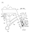
- FIG. 1 is a schematic two-sided view schematically showing a wire gripper 1A according to the first embodiment.
- a schematic front view is shown on the left side of FIG. 1, and a schematic side view is shown on the right side of FIG.
- FIG. 2 is a schematic perspective view schematically showing an example of the guide portion 16.
- FIG. 3 to 5 are schematic front views schematically showing the wire gripper 1A according to the first embodiment.
- FIG. 6 is a schematic front view schematically showing a wire gripper 1A in the first modified example of the first embodiment.
- FIG. 7 is a schematic front view schematically showing a wire gripper 1A in a second modification of the first embodiment.
- FIG. 8 is a schematic front view schematically showing a wire gripper 1A in a third modified example of the first embodiment. 1, 3 to 8, the lower end portion 20 of the base member 10 is shown in cross-sectional view in order to facilitate understanding of the internal structure of the lower end portion 20.
- FIG. 8 is a schematic front view schematically showing a wire gripper 1A in a third modified example of the first embodiment. 1, 3 to 8, the lower end portion 20 of the base member 10 is shown in cross-sectional view in order to facilitate understanding of the internal structure of the lower end portion 20.
- a wire gripper 1A in the first embodiment includes a base member 10 (in other words, a first member), a second member 30, a swing member 40, and a lever member 50.
- the base member 10 has a first grip portion 11, and the first grip portion 11 has a first contact surface 11a that contacts the wire rod W (more specifically, the upper surface of the wire rod W).
- the cross-sectional shape of the first contact surface 11a perpendicular to the first direction DR1 is, for example, a curved shape concave upward.
- the base member 10 may be composed of one part or may be composed of an assembly of a plurality of parts.
- the second member 30 has a second grip portion 31, and the second grip portion 31 has a second contact surface 31a that contacts the wire rod W (more specifically, the lower surface of the wire rod W).
- the cross-sectional shape of the second contact surface 31a perpendicular to the first direction DR1 is, for example, a curved shape recessed downward.
- the second member 30 may be composed of one part or may be composed of an assembly of a plurality of parts.
- the first gripping portion 11 and the second gripping portion 31 grip the wire W as the first contact surface 11a and the second contact surface 31a contact the wire W.
- the wire W gripped by the first gripping portion 11 and the second gripping portion 31 is, for example, an electric wire (more specifically, an erection wire).
- the rocking member 40 is connected to the base member 10 so as to be rotatable about the first axis AX1. More specifically, the wire gripper 1A includes a first pin member P1 that rotatably couples the swing member 40 and the base member 10, and the first pin member P1 moves along the first axis AX1. are placed.
- the swing member 40 is connected to the second member 30 so as to be rotatable around the second axis AX2. More specifically, the wire gripper 1A includes a second pin member P2 that rotatably connects the swing member 40 and the second member 30, and the second pin member P2 is arranged along the second axis AX2. are placed.
- the rocking member 40 may be composed of one component, or may be composed of an assembly of a plurality of components. In the example shown in FIG.
- the rocking member 40 is a plate-like member. Further, the rocking member 40 has a substantially triangular shape when viewed from the front, and the above-described first axis AX1, the above-described second axis AX2, and the below-described third axis AX3 are respectively located at the apexes of the triangle. are placed.
- the shape and structure of the rocking member 40 are not limited to the example shown in FIG.
- the lever member 50 is connected to the swing member 40 so as to be rotatable about the third axis AX3. More specifically, the wire gripper 1A includes a third pin member P3 that rotatably connects the lever member 50 and the swing member 40, and the third pin member P3 moves along the third axis AX3. are placed.
- the swing member 40 connected to the lever member 50 swings around the first axis AX1.
- the second contact surface 31a of the second grip portion 31 moves toward the first contact surface 11a of the first grip portion 11, and as a result, the wire rod W moves toward the first contact surface 11a. It is gripped by the gripping portion 11 and the second gripping portion 31 .
- the second end 50b of the lever member 50 (the end opposite to the first end 50a connected to the swing member 40) is a free end. The free end is connected, for example, to an extendable rod member 70, which will be described later.
- the base member 10 includes, in addition to the first gripping portion 11, a guide portion 16, a first engaging portion 21a, and a first operating portion 26a.
- the guide portion 16 guides the movement of the lever member 50.
- the guide portion 16 is provided on the rear side portion (the portion on the first direction DR1 side) of the base member 10 .
- the guide portion 16 extends downward and rearward from the rear end of the first contact surface 11a (or the rear end of the second contact surface 31a).
- the guide portion 16 has a guide wall Gw that guides the lever member 50 .
- the guide wall Gw is, for example, a wall that defines a through hole Gh through which the intermediate portion 53 (see FIG. 1) of the lever member 50 is inserted.
- the guide portion 16 prevents the lever member 50 from being excessively displaced in the lateral direction (the direction perpendicular to the paper surface in the front view on the left side of FIG. 1). , to prevent an excessive load from acting on the connecting portion between the lever member 50 and the swing member 40 .
- the first engaging portion 21a can be engaged with the lever member 50 (more specifically, the second engaging portion 51 of the lever member 50).
- the base member 10 has a lower end portion 20 below the guide portion 16, and the first engaging portion 21a is provided at the lower end portion 20 and is relatively movable with respect to the lower end portion 20. is provided as follows.
- the portion of the first engaging portion 21a that contacts the lever member 50 is formed to have an acute angle when viewed in the direction parallel to the third axis AX3.
- the first operating portion 26a moves the first engaging portion 21a from the first state in which the engagement between the first engaging portion 21a and the lever member 50 is released (see FIG. 4A).
- the first engaging portion 21a is moved so as to be in the second state (see FIG. 4(b)) in which the first engaging portion 21a engages with the .
- the first operating portion 26a changes the arrangement state of the first engaging portion 21a from the first state to the second state.
- the first engaging portion 21a is shifted from the first state in which the engagement between the first engaging portion 21a and the lever member 50 is released. It can be forced to switch to a second state in which member 50 is engaged.
- FIG. 4B when the first engaging portion 21a is engaged with the lever member 50, the lever member 50 is prevented from moving relative to the base member 10 in the first direction DR1. be.
- the distance between the first grip portion 11 and the second grip portion 31 is maintained at a predetermined distance. Therefore, in the first embodiment, the state in which the first engaging portion 21a is engaged with the lever member 50 (in other words, the interval between the first gripping portion 11 and the second gripping portion 31 is set to a predetermined interval). maintained state), the wire W can be arranged between the first gripping portion 11 and the second gripping portion 31 . Therefore, the work of attaching the wire gripper 1A to the wire rod W can be easily carried out.
- the wire gripper 1A includes a first biasing member 91 .
- the first biasing member 91 biases the swinging member 40 in the first rotation direction R1 about the first axis AX1 so as to reduce the distance between the first gripping portion 11 and the second gripping portion 31. .
- the wire gripper 1A When the wire gripper 1A is provided with the first biasing member 91, the wire rod disposed between the first gripping portion 11 and the second gripping portion 31 is pulled using the biasing force of the first biasing member 91. W can be automatically gripped by both grippers (11, 31). Therefore, the work of gripping the wire W by the first gripping portion 11 and the second gripping portion 31 is made more efficient.
- the first biasing member 91 is a torsion coil spring in the example shown in FIG. good too.
- the wire gripper 1A (more specifically, the base member 10) includes a second biasing member 27.
- the second biasing member 27 biases the first engaging portion 21 a away from the lever member 50 .
- the biasing force of the second biasing member 27 causes the first engaging portion 21a to move toward the lever member 50 (more specifically, the lever member 50). Specifically, it automatically retracts in a direction away from the second engaging portion 51 (see FIG. 5(a)).
- the wire gripper 1A includes a second biasing member 27, and when the operating force acting on the first operating portion 26a is removed, the second biasing member 27 is applied.
- the biasing force of the member 27 By the biasing force of the member 27, the state of the first engaging portion 21a is changed from the second state (in other words, the state engaged with the lever member 50) to the first state (in other words, the state of engagement with the lever member 50). is released) automatically. Therefore, a complicated operation for disengaging the wire W is not required, and the work of gripping the wire W by the first gripping portion 11 and the second gripping portion 31 is made more efficient.
- the first engagement can be achieved simply by canceling the operation force acting on the first operation portion 26a.
- a series of operations from disengagement between the joining portion 21a and the lever member 50 to gripping of the wire W by the first gripping portion 11 and the second gripping portion 31 can be automated.
- the above automation is particularly useful when the manipulator M operates the first operation unit 26a.
- the wire rod W is moved by the first gripping portion 11 and the second gripping portion 31 from the disengagement of the engagement between the first engaging portion 21a and the lever member 50.
- a series of operations up to grasping can be automated. Therefore, the work burden on the worker is greatly reduced.
- the second biasing member 27 is a torsion coil spring, but the second biasing member 27 may be other types of springs (eg, coil springs). , a magnet, or the like.
- the wire gripper 1A (more specifically, the base member 10) has an engaging member 21, a second guide portion 22a, and a link mechanism 23. As shown in FIG. 3, the wire gripper 1A (more specifically, the base member 10) has an engaging member 21, a second guide portion 22a, and a link mechanism 23. As shown in FIG. 3, the wire gripper 1A (more specifically, the base member 10) has an engaging member 21, a second guide portion 22a, and a link mechanism 23. As shown in FIG.
- the engaging member 21 has a first engaging portion 21a and is guided by a second guide portion 22a so as to be advanceable and retractable (in other words, advanceable and retractable).
- the advancing direction of the engaging member 21 is the direction in which the engaging member 21 faces the lever member 50
- the retreating direction of the engaging member 21 is the direction in which the engaging member 21 moves away from the lever member 50 .
- the engaging member 21 has a sliding surface 21b that slides against the guide surface of the second guide portion 22a.
- the link mechanism 23 moves the engaging member 21 forward and backward.
- the link mechanism 23 includes multiple arms 241 and multiple swing axes AT.
- the link mechanism 23 includes a first arm 241a, a second arm 241b, a first swing axis AT1, a second swing axis AT2, and a third swing axis AT3.
- the number of arms and the number of pivot axes are not limited to the example shown in FIG.
- the first end of the first arm 241a is connected to the engaging member 21 so as to be able to swing about the first swing axis AT1
- the second end of the first arm 241a is connected to the second arm 241b so as to be able to swing about the second swing axis AT2.
- a first end of the second arm 241b is pivotably connected to the first arm 241a, and a second end of the second arm 241b is pivotable about a third pivot axis AT3. , to the lower end portion 20 (more specifically, the grip portion 22) of the base member 10. As shown in FIG.
- the first operation portion 26a is configured by an exposed portion P of the link mechanism 23 exposed from the second guide portion 22a. More specifically, in the example shown in FIG. 3, the second end of the first arm 241a and the first end of the second arm 241b are exposed from the second guide portion 22a. The end functions as the first operation portion 26a.
- a member that is attached to any one of the plurality of arms 24 and functions as the first operating portion 26a is also regarded as part of the link mechanism 23. As shown in FIG. For example, when a plate member or the like that functions as the first operating portion 26a is attached to the second end of the first arm 241a or the first end of the second arm 241b, the plate member is also attached to the link mechanism 23. considered part.
- the lever member 50 has a second engaging portion 51 that can be engaged with the first engaging portion 21a.
- the second engaging portion 51 is provided on the lower surface 50 s of the lever member 50 .
- the second engaging portion 51 is configured by a concave portion 51d provided in the lower surface 50s of the lever member 50.
- the first engaging portion 21a contacts the surface 511d of the recess 51d on the second direction DR2 side. .
- swinging member operation unit 46 In the example shown in FIG. 3, the swinging member 40 is provided with a swinging member operating portion 46 that rotates the swinging member 40 about the first axis AX1.
- the swinging member operating portion 46 is preferably provided at the lower end portion of the swinging member 40 .
- the rocking member operation portion 46 is configured by, for example, an operation ring.
- a first modified example is a modified example of a mechanism for advancing and retracting the first engaging portion 21a.
- the wire gripper 1A (more specifically, the base member 10) includes an engaging member 21, a second guide portion 22a, a first operating member 26, and a second biasing member. 27.
- the engaging member 21 includes a converting portion 211 that converts the movement of the first operating member 26 into forward and backward movement of the engaging member 21 .
- the conversion portion 211 includes a first inclined surface 211a. Otherwise, the engaging member 21 in the first modified example is the same as the engaging member 21 illustrated in FIG.
- the second guide portion 22a guides the movement of the engaging member 21. Since the structure or function of the second guide portion 22a has already been described, repeated description of the second guide portion 22a will be omitted.
- the first operating member 26 includes a first operating portion 26a and a pressing portion 26b.
- the pressing portion 26b includes a second inclined surface 261b.
- the second biasing member 27 biases the first engaging portion 21 a away from the lever member 50 .
- the second biasing member 27 is a coil spring.
- the engagement between the first engaging portion 21a of the engaging member 21 and the lever member 50 is released.
- the engaging member 21 retreats away from the lever member 50
- the first inclined surface 211 a of the engaging member 21 presses the second inclined surface 261 b of the first operating member 26 .
- the first operating member 26 returns to its original position (in other words, default position).
- the example of using the first inclined surface 211a and the second inclined surface 261b as a mechanism for converting the movement of the first operating member 26 into the advance/retraction of the engaging member 21 has been described.
- a mechanism such as a screw or a gear may be employed as a mechanism for converting the movement of the first operating member 26 into the forward/backward movement of the engaging member 21 .
- the base member 10 is provided with a second operating member 28 in addition to the first operating portion 26a.
- the second operating member 28 is configured so that the first engaging portion 21a engages the lever member 50 (more specifically, the second engaging portion) from a first state in which the engagement between the first engaging portion 21a and the lever member 50 is released.
- the first engaging portion 21a is moved so as to be in the second state of engaging with the joining portion 51).
- the second operating member 28 can maintain the first engaging portion 21a at the advanced position to engage with the lever member 50 even when the operating force acting on the second operating portion 28a of the second operating member 28 disappears.
- the second operation in which the first engaging portion 21a does not automatically retract from the lever member 50 can be selected even when the operating force acting on the second operating portion 28a is lost.
- the first operation is selected. 2 operations may be selected.
- the lever member 50 is provided with a third engaging portion 57 separate from the second engaging portion 51 .
- the first engaging portion 21 a can selectively engage with the second engaging portion 51 or the third engaging portion 57 .
- movement of the lever member 50 in the second direction DR2 is restricted when the first engaging portion 21a and the third engaging portion 57 are engaged. Further, in the third modification, movement of the lever member 50 in the first direction DR1 is restricted when the first engaging portion 21a and the second engaging portion 51 are engaged.
- FIG. 9 is a schematic front view schematically showing a wire gripper 1B according to the second embodiment.
- FIG. 10 is a schematic front view schematically showing a wire gripper 1B in the first modified example of the second embodiment. 9 and 10, in order to facilitate understanding of the internal structure of the lower end portion 20 of the base member 10, a cross-sectional view of the lower end portion 20 is shown.
- a wire gripper 1B in the second embodiment includes (1) a base member 10 having a first gripping portion 11 that contacts the wire, and (2) a second grip that contacts the wire. (3) a second member 30 having a portion 31; (4) a lever member 50 rotatably connected to the swing member 40 about the third axis AX3; (5)
- the base member 10 includes a guide portion 16 that guides the movement of the lever member 50, a first engaging portion 21a that can be engaged with the lever member 50, and a first operating portion 26a.
- the first operating portion 26a changes from the first state in which the engagement between the first engaging portion 21a and the lever member 50 is released to the second state in which the first engaging portion 21a engages the lever member 50. , the first engaging portion 21a is moved.
- the second embodiment has the same effect as the first embodiment.
- the wire gripper 1B (more specifically, the base member 10) includes a threaded rod 26c that converts the operating force acting on the first operating portion 26a into movement of the first engaging portion 21a.
- the threaded rod 26c is screwed with the lower end portion 20 of the base member 10 .
- each of the first operating portion 26a and the threaded rod 26c constitutes at least part of the first operating member 26.
- the first operating member 26 includes a first operating portion 26a and a threaded rod 26c.
- the first operating portion 26a is connected to the threaded rod 26c, and the threaded rod 26c is connected to the engaging member 21.
- the first operation part 26a is configured by an operation ring that can be engaged with a remote control member.
- the threaded rod 26c advances in the direction from the proximal end of the threaded rod 26c to the distal end of the threaded rod 26c. do.
- the engaging member 21 advances toward the lever member 50 together with the threaded rod 26c, and the first engaging portion 21a of the engaging member 21 and the lever member 50 (more specifically, the second engaging portion 51) are engaged. are engaged (see FIG. 9(b)).
- FIG. 9B the engaged state between the first engaging portion 21a and the lever member 50 is maintained even when the operating force acting on the first operating portion 26a is lost.
- the engaged state between the first engaging portion 21a and the lever member 50 is maintained even when the operating force acting on the first operating portion 26a disappears. Therefore, when a worker attaches the wire gripper 1B to the wire rod W using a remote control tool, the worker can stably carry out the work.
- the lever member 50 is provided with a third engaging portion 57 separate from the second engaging portion 51 .
- the first engaging portion 21 a can selectively engage with the second engaging portion 51 or the third engaging portion 57 .
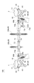
- FIG. 11 is a schematic front view schematically showing the wire rod cutting tool 100 according to the third embodiment.
- a wire rod cutting tool 100 in the third embodiment includes a wire gripper 1, a second wire gripper 2, and an extendable bar member 70.
- the wire gripper 1 of the wire rod cutting tool 100 in the third embodiment As the wire gripper 1 of the wire rod cutting tool 100 in the third embodiment, the wire gripper 1A in the first embodiment may be adopted, or the wire gripper 1B in the second embodiment may be adopted. good.
- the wire gripper 1 is an instrument that grips the first portion of the wire W. Since the wire gripper 1 has already been described in the first embodiment or the second embodiment, a repeated description of the wire gripper 1 will be omitted.
- the wire gripper 1A in the first embodiment may be adopted, or the wire gripper 1B in the second embodiment may be adopted.
- other wire grippers may be employed.
- the base member 10, the second member 30, the swing member 40, the lever member 50, the first engaging portion 21a, and the first operating portion 26a have already been described in the first embodiment or the second embodiment. Therefore, a repetitive description of these configurations will be omitted.
- the extendable rod member 70 is connected to the wire gripper 1 (more specifically, the second end 50b of the lever member 50 of the wire gripper 1).
- the extendable rod member 70 is connected to the second wire gripper 2 (more specifically, the second end 50b of the lever member 50 of the second wire gripper 2).
- the extendable bar member 70 is a member for changing the distance between the wire gripper 1 and the second wire gripper 2 .
- the first end 70 a of the bar member 70 is connected to the wire gripper 1 and the second end 70 b of the bar member 70 is connected to the second wire gripper 2 .
- the rod member 70 With the wire gripper 1 gripping the first portion of the wire W and the second wire gripper 2 gripping the second portion of the wire W, the rod member 70 is moved in the direction along the longitudinal axis L1 of the rod member. , the distance between the wire gripper 1 and the second wire gripper 2 is reduced. As a result, the portion of the wire rod W located between the wire gripper 1 and the second wire gripper 2 is loosened.
- the rod member 70 includes an outer member 71, an inner member 72, and an operating portion 73.
- the operating portion 73 is a portion for operating the relative movement of the inner member 72 with respect to the outer member 71 .
- the operating portion 73 is connected to the rod member 70 and is rotatable around the fourth axis AX4.
- the operating portion 73 includes an engaging portion 730 with which the distal end of the remote control member engages.
- the mechanism for contracting the bar member 70 is not limited to the mechanism described above.
- the wire rod cutting tool 100 may include at least one wire support 80 from the viewpoint of efficiently performing the work of separating the first cut end portion and the second cut end portion.
- the wire support 80 is a member that supports the wire W in the region between the wire gripper 1 and the second wire gripper 2 .
- the wire cutting tool 100 includes a first wire support 80a and a second wire support 80b.
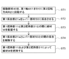
- the method of using the wire gripper 1 in the embodiment is the method of using the wire gripper 1A in the first embodiment or the wire gripper 1B in the second embodiment.
- the first step ST1 (swinging member rotating step) is executed by operating the swinging member operating section 46. More specifically, when the swinging member operating portion 46 is pulled downward, the swinging member 40 rotates about the first axis AX1 in the second rotation direction R2. Alternatively, the first step ST1 (swing member rotating step) may be performed by moving the lever member 50 in the second direction DR2.
- FIG. 4(a) shows the state after the first step ST1 is executed.
- the first engaging portion 21a is engaged with the lever member 50 (more specifically, the second engaging portion 51).
- the second step ST2 is an engagement step.
- the first operating portion 26a is operated by the manipulator M or an arbitrary tool to move the first engaging portion 21a to the lever member 50 (more specifically, the second engaging portion). moving toward the junction 51). This movement causes the first engaging portion 21a to engage with the lever member 50 (more specifically, the second engaging portion 51).
- FIGS. 6(b) and 9(b) show the state after the second step ST2 is executed.
- a fourth step ST4 is an engagement release step.
- the fourth step ST4 may include operating the first operating portion 26a with a remote control tool.
- the threaded rod 26c moves together with the first engaging portion 21a to the lever member. 50 (more specifically, second engaging portion 51).
- the engagement between the first engaging portion 21a and the lever member 50 is released.
- a fifth step ST5 is a wire gripping step.
- the fifth step ST5 (wire gripping step) is executed by rotating the swing member 40 in the first rotation direction R1 about the first axis AX1. As the swing member 40 rotates about the first axis AX1 in the first rotation direction R1, the distance between the first gripping portion 11 and the second gripping portion 31 is reduced, and the wire rod W is rotated in the first rotation direction R1. It is gripped by the gripping portion 11 and the second gripping portion 31 .
- the biasing force of the first biasing member 91 causes the swinging member 40 to rotate about the first axis AX1 in the first rotation direction. Rotating to R1 may be included.
- the fifth step ST5 (wire gripping step) may include the lever member 50 pulling the rocking member 40 in the first direction DR1.
- the third step ST3 (arranging step) is performed while the distance between the first gripping portion 11 and the second gripping portion 31 is maintained at a predetermined distance. be. Therefore, the work of attaching the wire gripper 1A to the wire rod W can be easily performed.
- the distance between the first gripping portion and the second gripping portion of the wire gripper can be maintained at a predetermined distance. becomes possible. Therefore, the wire gripper can be easily attached to the wire. Therefore, it is useful for those who attach wire grippers or wire rod cutting tools to wire rods, and for manufacturers who manufacture wire grippers or wire rod cutting tools.
Landscapes
- Engineering & Computer Science (AREA)
- General Engineering & Computer Science (AREA)
- Mechanical Engineering (AREA)
- Electric Cable Installation (AREA)
- Mechanical Control Devices (AREA)
- Processing Of Stones Or Stones Resemblance Materials (AREA)
Priority Applications (3)
| Application Number | Priority Date | Filing Date | Title |
|---|---|---|---|
| JP2023520906A JP7818836B2 (ja) | 2021-05-13 | 2022-03-25 | 掴線器、線材切分工具、および、掴線器の使用方法 |
| KR1020237042000A KR20240007198A (ko) | 2021-05-13 | 2022-03-25 | 와이어 그리퍼, 선재 절분 공구 및 와이어 그리퍼 사용방법 |
| CN202290000426.5U CN221126747U (zh) | 2021-05-13 | 2022-03-25 | 紧线器、以及线材切割工具 |
Applications Claiming Priority (2)
| Application Number | Priority Date | Filing Date | Title |
|---|---|---|---|
| JP2021-081998 | 2021-05-13 | ||
| JP2021081998 | 2021-05-13 |
Publications (1)
| Publication Number | Publication Date |
|---|---|
| WO2022239533A1 true WO2022239533A1 (ja) | 2022-11-17 |
Family
ID=84029574
Family Applications (1)
| Application Number | Title | Priority Date | Filing Date |
|---|---|---|---|
| PCT/JP2022/014396 Ceased WO2022239533A1 (ja) | 2021-05-13 | 2022-03-25 | 掴線器、線材切分工具、および、掴線器の使用方法 |
Country Status (5)
| Country | Link |
|---|---|
| JP (1) | JP7818836B2 (https=) |
| KR (1) | KR20240007198A (https=) |
| CN (1) | CN221126747U (https=) |
| TW (1) | TWI832224B (https=) |
| WO (1) | WO2022239533A1 (https=) |
Citations (2)
| Publication number | Priority date | Publication date | Assignee | Title |
|---|---|---|---|---|
| JPH0543710U (ja) * | 1991-11-19 | 1993-06-11 | 北陸電力株式会社 | 離隔器置換機能を有する引留具 |
| WO2015115451A1 (ja) * | 2014-01-30 | 2015-08-06 | 株式会社永木精機 | 掴線器 |
Family Cites Families (5)
| Publication number | Priority date | Publication date | Assignee | Title |
|---|---|---|---|---|
| JP5850800B2 (ja) | 2012-05-24 | 2016-02-03 | 株式会社永木精機 | 掴線器 |
| CN216016273U (zh) * | 2019-01-12 | 2022-03-11 | 株式会社永木精机 | 紧线器及线材切割工具 |
| KR102740331B1 (ko) * | 2019-01-12 | 2024-12-10 | 가부시키가이샤나가키세이키 | 와이어 그리퍼, 및, 선재 절분 공구 |
| JP7038680B2 (ja) | 2019-03-05 | 2022-03-18 | 株式会社永木精機 | 掴線器並びに電線の支持及び張緩用器具 |
| EP3993195A4 (en) | 2019-06-27 | 2023-07-05 | Nagaki Seiki Co., Ltd. | Gripping tool |
-
2022
- 2022-03-25 JP JP2023520906A patent/JP7818836B2/ja active Active
- 2022-03-25 KR KR1020237042000A patent/KR20240007198A/ko active Pending
- 2022-03-25 WO PCT/JP2022/014396 patent/WO2022239533A1/ja not_active Ceased
- 2022-03-25 CN CN202290000426.5U patent/CN221126747U/zh active Active
- 2022-04-26 TW TW111115906A patent/TWI832224B/zh active
Patent Citations (2)
| Publication number | Priority date | Publication date | Assignee | Title |
|---|---|---|---|---|
| JPH0543710U (ja) * | 1991-11-19 | 1993-06-11 | 北陸電力株式会社 | 離隔器置換機能を有する引留具 |
| WO2015115451A1 (ja) * | 2014-01-30 | 2015-08-06 | 株式会社永木精機 | 掴線器 |
Also Published As
| Publication number | Publication date |
|---|---|
| JPWO2022239533A1 (https=) | 2022-11-17 |
| TWI832224B (zh) | 2024-02-11 |
| TW202245367A (zh) | 2022-11-16 |
| CN221126747U (zh) | 2024-06-11 |
| KR20240007198A (ko) | 2024-01-16 |
| JP7818836B2 (ja) | 2026-02-24 |
Similar Documents
| Publication | Publication Date | Title |
|---|---|---|
| KR102021001B1 (ko) | 활선 작업용 수동 기계식 다기능 절연 기어 그립퍼 플라이어 스틱 및 이를 이용한 간접 활선공법 | |
| US7121166B2 (en) | Power tong assembly | |
| JP5268537B2 (ja) | 活線切分工具 | |
| MX348465B (es) | Aparato y método para el manejo de tubería. | |
| WO2011001502A1 (ja) | 掴線器 | |
| JP2003516233A (ja) | リベット締め工具 | |
| EP2851504A1 (de) | Bohrgestängegreifer | |
| CN113826290A (zh) | 抓具 | |
| JP2009233790A (ja) | ロボットの関節構造、ロボットフィンガ及びロボットハンド | |
| JP4188719B2 (ja) | 掴線器 | |
| WO2022239533A1 (ja) | 掴線器、線材切分工具、および、掴線器の使用方法 | |
| US11664634B2 (en) | Wire operating tool and component for wire operating tool | |
| JP5602259B2 (ja) | 間接活線作業用の先端工具及び間接活線工具 | |
| JP5421483B2 (ja) | 活線切分工具及びそれを使用した活線切分工法 | |
| JP5249700B2 (ja) | 遠隔操作用作業器具 | |
| KR20190015427A (ko) | 간접활선용 다용도 집게 | |
| JP7186463B2 (ja) | 工具 | |
| WO2020261638A1 (ja) | 把持工具、および、把持工具の使用方法 | |
| JP7287711B2 (ja) | 掴線器、および、線材切分工具 | |
| JP4977559B2 (ja) | 遠隔操作用ヤットコ | |
| CN103909478B (zh) | 一种用于狭小操作空间的柔性切断夹钳及使用方法 | |
| WO2022054591A1 (ja) | 把持工具、および、把持工具の使用方法 | |
| JP7814760B2 (ja) | 固定具、電線切分工具、および、固定方法 | |
| JP5758446B2 (ja) | 間接活線工事用工具 | |
| CN210598867U (zh) | 一种管柱夹持机构 |
Legal Events
| Date | Code | Title | Description |
|---|---|---|---|
| 121 | Ep: the epo has been informed by wipo that ep was designated in this application |
Ref document number: 22807238 Country of ref document: EP Kind code of ref document: A1 |
|
| WWE | Wipo information: entry into national phase |
Ref document number: 2023520906 Country of ref document: JP |
|
| WWE | Wipo information: entry into national phase |
Ref document number: 202290000426.5 Country of ref document: CN |
|
| ENP | Entry into the national phase |
Ref document number: 20237042000 Country of ref document: KR Kind code of ref document: A |
|
| WWE | Wipo information: entry into national phase |
Ref document number: 1020237042000 Country of ref document: KR |
|
| NENP | Non-entry into the national phase |
Ref country code: DE |
|
| 122 | Ep: pct application non-entry in european phase |
Ref document number: 22807238 Country of ref document: EP Kind code of ref document: A1 |