WO2022239398A1 - 電磁石及び荷電粒子加速装置 - Google Patents
電磁石及び荷電粒子加速装置 Download PDFInfo
- Publication number
- WO2022239398A1 WO2022239398A1 PCT/JP2022/008972 JP2022008972W WO2022239398A1 WO 2022239398 A1 WO2022239398 A1 WO 2022239398A1 JP 2022008972 W JP2022008972 W JP 2022008972W WO 2022239398 A1 WO2022239398 A1 WO 2022239398A1
- Authority
- WO
- WIPO (PCT)
- Prior art keywords
- charged particle
- electromagnet
- iron core
- vacuum duct
- particle beam
- Prior art date
- Legal status (The legal status is an assumption and is not a legal conclusion. Google has not performed a legal analysis and makes no representation as to the accuracy of the status listed.)
- Ceased
Links
Images


Classifications
-
- H—ELECTRICITY
- H05—ELECTRIC TECHNIQUES NOT OTHERWISE PROVIDED FOR
- H05H—PLASMA TECHNIQUE; PRODUCTION OF ACCELERATED ELECTRICALLY-CHARGED PARTICLES OR OF NEUTRONS; PRODUCTION OR ACCELERATION OF NEUTRAL MOLECULAR OR ATOMIC BEAMS
- H05H7/00—Details of devices of the types covered by groups H05H9/00, H05H11/00, H05H13/00
- H05H7/04—Magnet systems, e.g. undulators, wigglers; Energisation thereof
-
- H—ELECTRICITY
- H01—ELECTRIC ELEMENTS
- H01F—MAGNETS; INDUCTANCES; TRANSFORMERS; SELECTION OF MATERIALS FOR THEIR MAGNETIC PROPERTIES
- H01F7/00—Magnets
- H01F7/06—Electromagnets; Actuators including electromagnets
- H01F7/20—Electromagnets; Actuators including electromagnets without armatures
- H01F7/202—Electromagnets for high magnetic field strength
-
- H—ELECTRICITY
- H05—ELECTRIC TECHNIQUES NOT OTHERWISE PROVIDED FOR
- H05H—PLASMA TECHNIQUE; PRODUCTION OF ACCELERATED ELECTRICALLY-CHARGED PARTICLES OR OF NEUTRONS; PRODUCTION OR ACCELERATION OF NEUTRAL MOLECULAR OR ATOMIC BEAMS
- H05H13/00—Magnetic resonance accelerators; Cyclotrons
- H05H13/04—Synchrotrons
-
- H—ELECTRICITY
- H05—ELECTRIC TECHNIQUES NOT OTHERWISE PROVIDED FOR
- H05H—PLASMA TECHNIQUE; PRODUCTION OF ACCELERATED ELECTRICALLY-CHARGED PARTICLES OR OF NEUTRONS; PRODUCTION OR ACCELERATION OF NEUTRAL MOLECULAR OR ATOMIC BEAMS
- H05H7/00—Details of devices of the types covered by groups H05H9/00, H05H11/00, H05H13/00
- H05H7/001—Arrangements for beam delivery or irradiation
-
- H—ELECTRICITY
- H05—ELECTRIC TECHNIQUES NOT OTHERWISE PROVIDED FOR
- H05H—PLASMA TECHNIQUE; PRODUCTION OF ACCELERATED ELECTRICALLY-CHARGED PARTICLES OR OF NEUTRONS; PRODUCTION OR ACCELERATION OF NEUTRAL MOLECULAR OR ATOMIC BEAMS
- H05H7/00—Details of devices of the types covered by groups H05H9/00, H05H11/00, H05H13/00
- H05H7/04—Magnet systems, e.g. undulators, wigglers; Energisation thereof
- H05H2007/046—Magnet systems, e.g. undulators, wigglers; Energisation thereof for beam deflection
Definitions
- An embodiment of the present invention relates to an electromagnet and a charged particle accelerator equipped with this electromagnet.
- a charged particle accelerator is a device that accelerates charged particles such as electrons and protons to a high energy state.
- a charged particle beam extracted from this charged particle accelerator is used in a wide range of fields, such as particle beam therapy for cancer, elementary particle physics research, and development of new materials.
- the trajectory and shape of the charged particle beam are controlled mainly by electromagnets.
- a charged particle beam is deflected by the magnetic field of a bending electromagnet so as to circulate inside a vacuum duct installed in a ring, and the diffusion of the charged particle beam is performed by a quadrupole electromagnet and a sextupole. Suppressed by an electromagnet.
- charged particles are kicked out by an electrostatic deflector, and the kicked-out and separated charged particle beam is deflected to the outside of the beam orbit by a septum electromagnet to utilize the charged particle beam. is sent to the beam transport system for
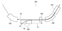
- a conventional synchrotron beam emission unit 100 shown in FIG. 7 includes an electrostatic deflector 101, a bending electromagnet 102, a quadrupole electromagnet 103, and a septum electromagnet 104, which are sequentially arranged.
- this beam emission unit 100 only the emitted charged particle beam needs to be deflected by the magnetic field in the septum electromagnet 104. Therefore, the beam trajectory 1A of the circulating charged particle beam and the beam emission trajectory of the charged particle beam to be emitted are It is necessary to secure a sufficient separation (separation distance) from 1B.
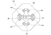
- the trajectory of the charged particle beam is confined within the vacuum duct 107 at the central position of the iron core 106 around which the excitation coil 105 is wound. . Therefore, the emitted beam 2B on the beam emission orbit 1B must travel near the center of the quadrupole electromagnet 103 at a shallow angle close to the circulating beam 2A on the beam circulating orbit 1A. Therefore, in order to obtain a sufficient separation (separation distance) between the beam orbit 1A and the beam exit orbit 1B, the length L0 of the straight portion from the quadrupole electromagnet 103 to the septum electromagnet 104 must be set large. This is a factor in lowering the design likelihood of the beam emitting section 100 .
- Embodiments of the present invention have been made in consideration of the above circumstances, and avoiding interference between the trajectory of the separated charged particle beam and the electromagnet, while avoiding interference between the trajectory of the separated charged particle beam and the main area.
- An object of the present invention is to provide an electromagnet and a charged particle accelerator capable of ensuring a sufficient separation distance from the trajectory of a charged particle beam.
- FIG. 2 is a plan view showing a beam emitting portion of a synchrotron equipped with quadrupole magnets and bending magnets to which the electromagnets according to the first embodiment are applied;
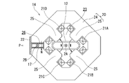
- FIG. 2 is a front view showing the quadrupole electromagnet in FIG. 1;
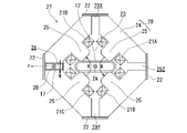
- FIG. 3 is a front view showing a first modification of the quadrupole electromagnet of FIG. 2;
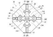
- FIG. 3 is a front view showing a second modification of the quadrupole electromagnet of FIG. 2;
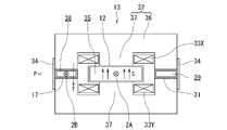
- FIG. 2 is a front view showing the bending electromagnet of FIG. 1;
- FIG. 11 is a front view showing a quadrupole electromagnet of a beam transport system to which the electromagnet according to the second embodiment is applied;
- FIG. 2 is a plan view showing a beam emission part of a conventional synchrotron;
- FIG. 8 is a front view showing the quadrupole electromagnet of FIG. 7;
- FIG. 1 is a plan view showing a beam emission part of a synchrotron equipped with a quadrupole electromagnet and a bending electromagnet to which the electromagnet according to the first embodiment is applied.
- a synchrotron 10 as a charged particle accelerator circulates and accelerates charged particles such as protons and electrons to bring them into a high-energy state. It comprises an electromagnet and a high frequency acceleration cavity (both not shown).
- the main vacuum duct 12 is installed in a ring, and a charged particle beam travels through it.
- the bending electromagnet 13 deflects the charged particle beam in the main vacuum duct 12 by the generated magnetic field and circulates the charged particle beam in the main vacuum duct 12 .
- the quadrupole 14 and sextupole electromagnets focus the charged particle beam in the main vacuum duct 12 and suppress its spread.
- a radio frequency acceleration cavity accelerates the charged particle beam traveling in orbit within the main vacuum duct 12 .
- the charged particle beam traveling around the main vacuum duct 12 will be referred to as a circulating beam 2A, and its trajectory will be referred to as a circulating beam trajectory 1A.
- the charged particle beam accelerated by the synchrotron 10 is emitted from the beam emission part 11 of the synchrotron 10 shown in FIG. You will be guided to each device for research, etc.
- the beam emitting section 11 is constructed by sequentially arranging an electrostatic deflector 15 , a bending electromagnet 13 , a quadrupole electromagnet 14 and a septum electromagnet 16 , and further has a main vacuum duct 12 and a sub-vacuum duct 17 .
- the electrostatic deflector 15 kicks out the charged particles of the orbiting beam 2A that orbits the beam orbit 1A.
- the beam of charged particles kicked out by the electrostatic deflector 15 and separated from the beam orbit 1A travels through the sub-vacuum duct 17 and is deflected away from the beam orbit 1A by the magnetic field of the bending electromagnet 13. , resulting in an output beam 2B.
- the trajectory of this outgoing beam 2B is called a beam outgoing trajectory 1B.
- the emitted beam 2B traveling in the sub-vacuum duct 17 is again deflected away from the beam orbit 1A by the magnetic field of the quadrupole electromagnet 14, and further deflected by the septum electromagnet 16 in the direction away from the beam orbit 1A, sent to the beam transport system.
- the quadrupole electromagnet 14 in the beam output section 11 of the synchrotron 10 described above is shown in FIG. 2, its modified form is shown in FIGS. 3 and 4, and the bending electromagnet 13 in the beam output section 11 is shown in FIG.
- the quadrupole electromagnet 14 shown in FIG. 2 has an iron core 20, exciting coils 21A, 21B, 21C and 21D, a support member 22, and further has the aforementioned main vacuum duct 12 and sub-vacuum duct 17. .
- the iron core 20 of the quadrupole electromagnet 14 has a main region 23, which is a gap, at the center of the rectangular shape when viewed from the front. Further, the iron core 20 has four magnetic pole portions 25 protruding from a peripheral portion 24 facing the main region 23 toward the main region 23 at equal intervals, and a single beam passing gap 26 is formed in the peripheral portion 24 . be.
- the main region 23 is provided for propagating the circulating beam 2A
- the beam passage gap 26 is provided for propagating the emitted beam 2B.
- Exciting coils 21A, 21B, 21C, and 21D are wound around the four magnetic pole portions 25, respectively.
- the support member 22 is fixed across the periphery of the beam passage gap 26 in the peripheral portion 24 of the iron core 20, that is, at a position facing the beam passage gap 26, and supports the periphery of the beam passage gap 26 in the peripheral portion 24. to reinforce.
- This support member 22 is made of a non-magnetic material.
- a main vacuum duct 12 is arranged in the main region 23 of the iron core 20, and the circulating beam 2A travels inside this main vacuum duct 12.
- the main vacuum duct 12 is made of a non-magnetic material, and its interior is maintained in a vacuum, thereby suppressing beam loss with respect to the traveling circulating beam 2A.
- the circulating beam 2A traveling through the main vacuum duct 12 is converged to the central position of the main vacuum duct 12 by the magnetic field M excited by the excitation coils 21A to 21D, and diffusion is suppressed.
- a sub-vacuum duct 17 is arranged in the beam passage gap 26 of the iron core 20, and the emitted beam 2B separated from the beam orbit 1A travels inside this sub-vacuum duct 17.
- the sub-vacuum duct 17 is made of a non-magnetic material and is kept in a vacuum state, thereby suppressing beam loss with respect to the traveling emitted beam 2B.
- the emitted beam 2B traveling through the sub-vacuum duct 17 is deflected in a direction P away from the beam circular orbit 1A (circular beam 2A) by the magnetic field N generated in the beam passing gap 26.
- the iron core 20 in which the main region 23 and the beam passing gap 26 are formed as described above has its shape, including its thickness, adjusted so as to maintain the symmetry of the magnetic field of the quadrupole electromagnet 14 .
- a quadrupole electromagnet 27 shown in FIG. 3 is a first modification of the quadrupole electromagnet 14 .
- this quadrupole electromagnet 27 a main region 23 and a beam passing gap 26 are formed in an iron core 28, and beam non-passing gaps 29X, 29Y and 29Z are formed at symmetrical positions of the beam passing gap 26.
- the beam non-passing gap 29Z is formed at a position facing the beam passing gap 26, and the beam non-passing gaps 29X and 29Y are formed at positions separated from the beam passing gap 26 by 90 degrees in opposite directions.
- These beam non-passing gaps 29X, 29Y and 29Z are gaps through which the charged particle beam does not advance (pass).
- the beam non-passing gaps 29X, 29Y and 29Z are formed in the same shape as the beam passing gap 26, thereby maintaining the symmetry of the magnetic field of the quadrupole electromagnet 27.
- the support members 22 are spanned and fixed to the iron core 28, The perimeters of the beam non-passing gaps 29X-29Z of the iron core 28 are supported and reinforced.
- a quadrupole electromagnet 30 shown in FIG. 4 is a second modification of the quadrupole electromagnet 14 .
- the iron core is the iron core 28 of the first modified form, and each of the beam non-passing gaps 29X, 29Y, 29Z of this iron core 28 is provided with a structure 31 is placed.
- This structure 31 has the same configuration as the sub-vacuum duct 17 arranged in the beam passage gap 26, for example, it is formed in a cylindrical shape made of a non-magnetic material.
- the bending electromagnet 13 shown in FIG. 5 has the same configuration as the quadrupole electromagnet 30 of the second modified form of the quadrupole electromagnet 14 .
- the main region 35 is formed at the central position of the iron core 32 which is rectangular in front view, and the magnetic pole portion 37 protrudes toward the main region 35 at a position facing the peripheral portion 36 of the iron core 32 facing the main region 35 .
- Exciting coils 33X and 33Y are wound around the magnetic pole portions 37, respectively.
- a beam passing gap 38 is formed in the peripheral portion 36 of the iron core 32, and a beam non-passing gap 39 is formed at a position facing the beam passing gap 38.
- a support member 34 made of a non-magnetic material is hung around each of the beam passing gap 38 and the beam non-passing gap 39 in the peripheral portion 36 of the iron core 32, that is, at a position facing the beam passing gap 38 and the beam non-passing gap 39, respectively. delivered and fixed.
- the support member 34 supports and reinforces the beam passing gap 38 and the beam non-passing gap 39 in the peripheral portion 36 of the iron core 32 .
- the main vacuum duct 12 is arranged in the main region 35 of the iron core 32, and the circulating beam 2A travels inside this main vacuum duct 12.
- the circulating beam 2A traveling through the main vacuum duct 12 is deflected in its beam position by the magnetic field S excited by the excitation coils 33X and 33Y, and circulates within the main vacuum duct 12.
- a sub-vacuum duct 17 is arranged in the beam passage gap 38 of the iron core 32, and the emitted beam 2B separated from the beam orbit 1A travels inside this sub-vacuum duct 17.
- the emitted beam 2B traveling through the sub-vacuum duct 17 is deflected in a direction P away from the beam circular orbit 1A (circular beam 2A) by the magnetic field T generated in the beam passage gap 38.
- FIG. A structure 31 for strictly maintaining the symmetry of the magnetic field of the bending electromagnet 13 is arranged in the beam non-passing gap 39 of the iron core 32 .
- the quadrupole electromagnets 14, 27 and 30 of the first embodiment have the following effects (1) and (2).
- the bending electromagnet 13 also has the same effect as the quadrupole electromagnet 14 and the like.
- the iron cores 20, 28 of the quadrupole magnets 14, 27, and 30 provided in the beam emission section 11 of the synchrotron 10 have a main area 23 for propagating the circulating beam 2A, as well as a beam from the beam circulating orbit 1A.
- a beam passing gap 26 is provided for advancing the separately emitted emitted beam 2B. Therefore, while avoiding interference between the beam exit trajectory 1B of the exit beam 2B and the quadrupole magnets 14, 27 and 30, the beam exit trajectory 1B of the exit beam 2B in the sub-vacuum duct 17 and the circulating beam in the main vacuum duct 12 are maintained.
- a sufficient distance (separation) H shown in FIG. 1 from the beam orbit 1A of 2A can be ensured.
- the length L of the straight line portion from the quadrupole magnets 14, 27, 30 to the septum magnet 16 in the beam emission section 11 of the synchrotron 10 can be shortened compared to the conventional length L0 (FIG. 7) of the straight line portion. Therefore, it is possible to improve the design likelihood of the beam emitting section of the synchrotron 10 .
- the magnetic field N in 26 deflects the circulating beam 2A traveling in the main vacuum duct 12 in the main region 23 of the iron cores 20, 28 in a direction P away from the circulating beam trajectory 1A.
- the separation distance H shown in FIG. 1 between the beam emission trajectory 1B of the emitted beam 2B and the beam circulating trajectory 1A of the circulating beam 2A can be sufficiently ensured.
- the septum electromagnet 16 installed in the beam emission section 11 of the synchrotron 10 can be reduced or omitted. can be reduced.
- FIG. 6 is a front view showing a quadrupole electromagnet of a beam transport system to which the electromagnet according to the second embodiment is applied.
- the same parts as in the first embodiment are denoted by the same reference numerals as those in the first embodiment, so that the explanation is simplified or omitted.
- the quadrupole electromagnet 40 as the electromagnet of the second embodiment differs from the first embodiment in that the quadrupole electromagnet 40 is an electromagnet installed in the beam transport system, and the peripheral portion of the iron core 41 that constitutes the quadrupole electromagnet 40 42, a plurality of, for example, two beam passage gaps (beam passage gaps 26 and 43) are formed for the charged particle beams 2D and 2E separated from the beam trajectory 1C of the charged particle beam 2C to travel.
- beam passage gaps 26 and 43 beam passage gaps
- the quadrupole electromagnet 40 has an iron core 41, exciting coils 21A to 21D, and a support member 22, and further has a main vacuum duct 12 and a sub-vacuum duct 17.
- the iron core 41 has a main region 23, which is a gap, at the center of a rectangular shape in front view. Further, the iron core 41 has four magnetic pole portions 25 protruding from a peripheral portion 42 facing the main region 23 toward the main region 23 at equal intervals. 21D is wound.
- one beam passing gaps 26, 43 are formed at facing positions, and beam non-passing gaps 29X, 29Y are formed facing each other.
- the support members 22 are provided around the beam passing gaps 26, 43 and the beam non-passing gaps 29X, 29Y, that is, at positions facing the beam passing gaps 26, 43 and the beam non-passing gaps 29X, 29Y, respectively. are bridged and fixed, and the peripheries of the beam passing gaps 26, 43 and the beam non-passing gaps 29X, 29Y in the peripheral portion 42 of the core 41 are supported and reinforced.
- the main vacuum duct 12 is arranged within the main region 23 of the iron core 41 , and the charged particle beam 2C travels inside this main vacuum duct 12 .
- the charged particle beam 2C traveling through the main vacuum duct 12 is converged to the central position of the main vacuum duct 12 by the magnetic field M excited by the excitation coils 21A to 21D, and diffusion is suppressed.
- the trajectory of this charged particle beam 2C is the beam trajectory 1C.
- the sub-vacuum ducts 17 are arranged in the beam passage gaps 26, 43 of the iron core 41, respectively, and the charged particle beams 2D, 2E separated from the beam trajectory 1C travel inside these sub-vacuum ducts 17, respectively.
- the trajectory of the charged particle beam 2D is the beam trajectory 1D
- the trajectory of the charged particle beam 2E is the beam trajectory 1E.
- the charged particle beam 2D traveling in the sub-vacuum duct 17 arranged in the beam passage gap 26 is deflected in a direction P away from the beam trajectory 1C (charged particle beam 2C) by the magnetic field N generated in the beam passage gap 26.
- the charged particle beam 2E traveling in the sub-vacuum duct 17 arranged in the beam passage gap 43 is deflected in the direction Q away from the beam trajectory 1C (charged particle beam 2C) by the magnetic field K generated in the beam passage gap 43.
- the separating direction Q is opposite to the separating direction P, for example.
- the following effect (3) is achieved.
- the beam trajectory 1D of the charged particle beam 2D and the charged particle beam 2C A sufficient separation distance from the beam trajectory 1C and a separation distance between the beam trajectory 1E of the charged particle beam 2E and the beam trajectory 1C of the charged particle beam 2C can be secured.
- the quadrupole electromagnet 40 can deflect each charged particle beam (e.g., charged particle beams 2D, 2E) in different directions by selecting the beam passage gaps 26, 43 for each charged particle beam. .
- a single quadrupole electromagnet 40 can split charged particle beams (for example, charged particle beams 2D and 2E) in different directions at the same time.
Landscapes
- Physics & Mathematics (AREA)
- Engineering & Computer Science (AREA)
- Plasma & Fusion (AREA)
- Spectroscopy & Molecular Physics (AREA)
- Electromagnetism (AREA)
- Optics & Photonics (AREA)
- Power Engineering (AREA)
- Particle Accelerators (AREA)
Abstract
分離した荷電粒子ビームの軌道と電磁石との干渉を回避しつつ、分離した荷電粒子ビームの軌道とメイン領域を進行する荷電粒子ビームの軌道との離反距離を十分に確保できること。 四極電磁石(14)は、荷電粒子ビームである周回ビーム(2A)が進行するためのメイン領域(23)のほかに、分離した荷電粒子ビームである出射ビーム(2B)が進行するためのビーム通過ギャップ(26)が設けられた鉄心(20)と、鉄心に巻き回された励磁コイル(21A、21B、21C、21D)と、鉄心のメイン領域(23)に設けられて、内部を周回ビーム(2A)が進行するメイン真空ダクト(12)と、鉄心のビーム通過ギャップ(26)に設けられて、内部を出射ビーム(2B)が進行するサブ真空ダクト(17)と、を有して構成されている。
Description
本発明の実施形態は電磁石、及びこの電磁石を備えた荷電粒子加速装置に関する。
荷電粒子加速装置は、電子や陽子をはじめとする荷電粒子を加速し、高エネルギの状態にする装置である。この荷電粒子加速装置から取り出された荷電粒子ビームは、例えば癌の粒子線治療や素粒子物理研究、新素材の開発などの幅広い分野で用いられる。
一方、上述の荷電粒子加速装置では、荷電粒子ビームは主に電磁石によってその軌道や形状が制御される。例えば、荷電粒子加速装置としてのシンクロトロンにおいては、荷電粒子ビームは環状に設置された真空ダクトの内部を周回するように偏向電磁石の磁場によって偏向され、荷電粒子ビームの拡散は四極電磁石及び六極電磁石によって抑制される。シンクロトロンにおけるビームの出射部では、静電デフレクタにより荷電粒子を蹴り出し、この蹴り出されて分離された荷電粒子のビームをセプタム電磁石によりビーム周回軌道の外側へ偏向させて、荷電粒子ビームの利用のためにビーム輸送系に送られる。
図7に示す従来のシンクロトロンのビーム出射部100は、静電デフレクタ101、偏向電磁石102、四極電磁石103及びセプタム電磁石104が順次配置されてなる。このビーム出射部100では、出射される荷電粒子ビームのみをセプタム電磁石104内の磁場で偏向する必要があるため、周回する荷電粒子ビームのビーム周回軌道1Aと出射すべき荷電粒子ビームのビーム出射軌道1Bとのセパレーション(離反距離)を十分にとる必要がある。
しかしながら、セプタム電磁石104よりも上流側の四極電磁石103(図8参照)において、荷電粒子ビームの軌道は、励磁コイル105が巻き回される鉄心106の中央位置にある真空ダクト107内に制限される。そのため、ビーム出射軌道1Bの出射ビーム2Bは、四極電磁石103の中央付近を、ビーム周回軌道1Aの周回ビーム2Aに接近した浅い角度で進行しなければならない。従って、ビーム周回軌道1Aとビーム出射軌道1B間に十分なセパレーション(離反距離)を得るためには、四極電磁石103からセプタム電磁石104に至る直線部分の長さL0を大きく設定しなければならない。このことはビーム出射部100の設計尤度が低下する要因になっている。
本発明の実施形態は、上述の事情を考慮してなされたものであり、分離した荷電粒子ビームの軌道と電磁石との干渉を回避しつつ、分離した荷電粒子ビームの軌道とメイン領域を進行する荷電粒子ビームの軌道との離反距離を十分に確保できる電磁石及び荷電粒子加速装置を提供することを目的とする。
以下、本発明を実施するための形態を、図面に基づき説明する。
[A]第1実施形態(図1~図5)
図1は、第1実施形態に係る電磁石が適用された四極電磁石及び偏向電磁石を備えるシンクロトロンのビーム出射部を示す平面図である。荷電粒子加速装置としてのシンクロトロン10は、陽子や電子などの荷電粒子を周回させて加速し、高エネルギの状態にするものであり、メイン真空ダクト12、偏向電磁石13、四極電磁石14、六極電磁石及び高周波加速空胴(共に図示せず)を有して構成される。
[A]第1実施形態(図1~図5)
図1は、第1実施形態に係る電磁石が適用された四極電磁石及び偏向電磁石を備えるシンクロトロンのビーム出射部を示す平面図である。荷電粒子加速装置としてのシンクロトロン10は、陽子や電子などの荷電粒子を周回させて加速し、高エネルギの状態にするものであり、メイン真空ダクト12、偏向電磁石13、四極電磁石14、六極電磁石及び高周波加速空胴(共に図示せず)を有して構成される。
メイン真空ダクト12は、環状に設置されており、内部を荷電粒子ビームが進行する。偏向電磁石13は、発生する磁場によりメイン真空ダクト12内の荷電粒子ビームを偏向させて、この荷電粒子ビームをメイン真空ダクト12内で周回させる。四極電磁石14及び六極電磁石は、メイン真空ダクト12内の荷電粒子ビームを収束させてその拡散を抑制する。高周波加速空胴は、メイン真空ダクト12内を周回して進行する荷電粒子ビームを加速する。ここで、メイン真空ダクト12内を周回して進行する荷電粒子ビームを周回ビーム2Aと称し、その軌道をビーム周回軌道1Aと称する。
シンクロトロン10により加速された荷電粒子ビームは、図1に示すシンクロトロン10のビーム出射部11からビーム輸送系(図示せず)へ出射され、このビーム輸送系を経て粒子線治療や素粒子物理研究などのための各装置へ導かれる。上記ビーム出射部11は、静電デフレクタ15、偏向電磁石13、四極電磁石14及びセプタム電磁石16が順次配置されて構成され、更に、メイン真空ダクト12及びサブ真空ダクト17を有する。
静電デフレクタ15は、ビーム周回軌道1Aを周回する周回ビーム2Aの荷電粒子を蹴り出す。この静電デフレクタ15により蹴り出されてビーム周回軌道1Aから分離された荷電粒子のビームはサブ真空ダクト17内を進行し、偏向電磁石13の磁場により、ビーム周回軌道1Aから離反する方向に偏向されて出射ビーム2Bとなる。この出射ビーム2Bの軌道をビーム出射軌道1Bと称する。サブ真空ダクト17内を進行する出射ビーム2Bは、四極電磁石14の磁場により再度ビーム周回軌道1Aから離反する方向へ偏向され、セプタム電磁石16によりビーム周回軌道1Aから更に離反する方向に偏向されて、ビーム輸送系に送られる。
上述のシンクロトロン10のビーム出射部11における四極電磁石14を図2に示し、その変形形態を図3及び図4に示し、更に、ビーム出射部11における偏向電磁石13を図5に示す。
図2に示す四極電磁石14は、鉄心20、励磁コイル21A、21B、21C及び21D、並びに支持部材22を有し、更に、前述のメイン真空ダクト12及びサブ真空ダクト17を有して構成される。
四極電磁石14の鉄心20は、正面視矩形状の中央位置に空隙(ギャップ)であるメイン領域23が形成される。更に、鉄心20は、メイン領域23を臨む周辺部24から等間隔にメイン領域23へ向かって磁極部25が4本突設されると共に、周辺部24に単一のビーム通過ギャップ26が形成される。メイン領域23は周回ビーム2Aを進行させるために、ビーム通過ギャップ26は出射ビーム2Bを進行させるためにそれぞれ設けられたものである。
4本の各磁極部25に、励磁コイル21A、21B、21C、21Dがそれぞれ巻き回される。また、支持部材22は、鉄心20の周辺部24におけるビーム通過ギャップ26の周囲、つまりビーム通過ギャップ26を臨む位置に掛け渡されて固定され、周辺部24におけるビーム通過ギャップ26の周囲を支持して補強する。この支持部材22は、非磁性体にて構成される。
鉄心20のメイン領域23内にメイン真空ダクト12が配置され、このメイン真空ダクト12の内部を周回ビーム2Aが進行する。メイン真空ダクト12は非磁性体にて構成されると共に、内部が真空に保持されることで、進行する周回ビーム2Aに対しビーム損失を抑制する。このメイン真空ダクト12内を進行する周回ビーム2Aは、励磁コイル21A~21Dにより励起された磁場Mによってメイン真空ダクト12の中央位置に収束され、拡散が抑制される。
鉄心20のビーム通過ギャップ26内にサブ真空ダクト17が配置され、このサブ真空ダクト17の内部をビーム周回軌道1Aから分離した出射ビーム2Bが進行する。サブ真空ダクト17は、非磁性体にて構成されると共に、内部が真空に保持されることで、進行する出射ビーム2Bに対しビーム損失を抑制する。このサブ真空ダクト17内を進行する出射ビーム2Bは、ビーム通過ギャップ26に生じた磁場Nによってビーム周回軌道1A(周回ビーム2A)から離反する方向Pに偏向される。
上述のようにメイン領域23及びビーム通過ギャップ26が形成された鉄心20は、四極電磁石14の磁場の対称性を維持するように、その厚さを含めた形状が調整されている。
図3に示す四極電磁石27は四極電磁石14の第1変形形態である。この四極電磁石27では、鉄心28にメイン領域23及びビーム通過ギャップ26が形成されると共に、ビーム通過ギャップ26の対称な位置にビーム不通過ギャップ29X、29Y、29Zが形成されている。例えば、ビーム不通過ギャップ29Zは、ビーム通過ギャップ26に対向する位置に形成され、ビーム不通過ギャップ29X及び29Yは、ビーム通過ギャップ26に対し互いに反対方向に90度離れた位置に形成される。これらのビーム不通過ギャップ29X、29Y及び29Zは、荷電粒子ビームが進行(通過)しないギャップである。
ビーム不通過ギャップ29X、29Y及び29Zは、ビーム通過ギャップ26と同様な形状に形成され、これにより、四極電磁石27の磁場の対称性が維持される。また、鉄心28には、ビーム不通過ギャップ29X、29Y、29Zのそれぞれの周囲に、つまりビーム不通過ギャップ29X、29Y、29Zのそれぞれを臨む位置に支持部材22が掛け渡されて固定されて、鉄心28のビーム不通過ギャップ29X~29Zのそれぞれの周囲が支持されて補強される。
図4に示す四極電磁石30は四極電磁石14の第2変形形態である。この四極電磁石30では、鉄心は第1変形形態の鉄心28であり、この鉄心28のビーム不通過ギャップ29X、29Y、29Zのそれぞれに、四極電磁石30の磁場の対称性をより厳密に維持するための構造物31が配置される。この構造物31は、ビーム通過ギャップ26に配置されたサブ真空ダクト17と同様な構成、例えば非磁性体製の筒形状に形成される。
図5に示す偏向電磁石13は、四極電磁石14の第2変形形態の四極電磁石30と同様な構成である。つまり、正面視矩形状の鉄心32の中央位置にメイン領域35が形成され、鉄心32はメイン領域35を臨む周辺部36の対向位置に、メイン領域35へ向かって磁極部37が突設される。各磁極部37に励磁コイル33X、33Yがそれぞれ巻き回される。
鉄心32の周辺部36には、ビーム通過ギャップ38が形成されると共に、このビーム通過ギャップ38の対向位置にビーム不通過ギャップ39が形成される。鉄心32の周辺部36におけるビーム通過ギャップ38とビーム不通過ギャップ39のそれぞれの周囲、つまりビーム通過ギャップ38とビーム不通過ギャップ39のそれぞれを臨む位置に、非磁性体製の支持部材34が掛け渡されて固定される。この支持部材34が、鉄心32の周辺部36におけるビーム通過ギャップ38、ビーム不通過ギャップ39のそれぞれの周囲を支持して補強する。
鉄心32のメイン領域35内にメイン真空ダクト12が配置され、このメイン真空ダクト12の内部を周回ビーム2Aが進行する。このメイン真空ダクト12内を進行する周回ビーム2Aは、励磁コイル33X及び33Yにより励起される磁場Sによってビーム位置が偏向されて、メイン真空ダクト12内を周回する。
鉄心32のビーム通過ギャップ38内にサブ真空ダクト17が配置され、このサブ真空ダクト17の内部をビーム周回軌道1Aから分離した出射ビーム2Bが進行する。このサブ真空ダクト17を進行する出射ビーム2Bは、ビーム通過ギャップ38に生じた磁場Tによってビーム周回軌道1A(周回ビーム2A)から離反する方向Pに偏向される。また、鉄心32のビーム不通過ギャップ39内に、偏向電磁石13の磁場の対称性を厳密に維持するための構造物31が配置されている。
以上のように構成されたことから、本第1実施形態の四極電磁石14、27及び30によれば、次の効果(1)及び(2)を奏する。偏向電磁石13においても、四極電磁石14等と同様な効果を奏する。
(1)シンクロトロン10のビーム出射部11に設けられた四極電磁石14、27及び30の鉄心20、28には、周回ビーム2Aを進行させるためのメイン領域23のほかに、ビーム周回軌道1Aから分離して出射する出射ビーム2Bを進行させるためのビーム通過ギャップ26が設けられている。このため、出射ビーム2Bのビーム出射軌道1Bと四極電磁石14、27及び30との干渉を回避しつつ、サブ真空ダクト17内の出射ビーム2Bのビーム出射軌道1Bとメイン真空ダクト12内の周回ビーム2Aのビーム周回軌道1Aとの図1に示す離反距離(セパレーション)Hを十分に確保することができる。この結果、シンクロトロン10のビーム出射部11における四極電磁石14、27、30からセプタム電磁石16に至る直線部分の長さLを、従来の直線部分の長さL0(図7)に比べて短縮できるので、シンクロトロン10のビーム出射部の設計尤度を向上させることができる。
(2)ビーム周回軌道1Aから分離して出射するサブ真空ダクト17内の出射ビーム2Bは、四極電磁石14、27、30の鉄心20、28のビーム通過ギャップ26を進行するとき、このビーム通過ギャップ26内の磁場Nによって、鉄心20、28のメイン領域23のメイン真空ダクト12内を進行する周回ビーム2Aのビーム周回軌道1Aから離反する方向Pに偏向される。この観点からも、出射ビーム2Bのビーム出射軌道1Bと周回ビーム2Aのビーム周回軌道1Aとの図1に示す離反距離(セパレーション)Hを、更に十分に確保できる。この結果、シンクロトロン10のビーム出射部11に設置されたセプタム電磁石16を削減または省略できるので、ビーム出射部11における直線部分の長さLの短縮と相俟って、シンクロトロン10の設置面積を減少させることができる。
[B]第2実施形態(図6)
図6は、第2実施形態に係る電磁石が適用されたビーム輸送系の四極電磁石を示す正面図である。この第2実施形態において第1実施形態と同様な部分ついては、第1実施形態と同一の符号を付すことにより説明を簡略化し、または省略する。
図6は、第2実施形態に係る電磁石が適用されたビーム輸送系の四極電磁石を示す正面図である。この第2実施形態において第1実施形態と同様な部分ついては、第1実施形態と同一の符号を付すことにより説明を簡略化し、または省略する。
本第2実施形態の電磁石としての四極電磁石40が第1実施形態と異なる点は、四極電磁石40がビーム輸送系に設置された電磁石であると共に、この四極電磁石40を構成する鉄心41の周辺部42に、荷電粒子ビーム2Cのビーム軌道1Cから分離した荷電粒子ビーム2D、2Eが進行するためのビーム通過ギャップが複数、例えば2個(ビーム通過ギャップ26及び43)が形成された点である。
つまり、四極電磁石40は、鉄心41、励磁コイル21A~21D、及び支持部材22を有し、更に、メイン真空ダクト12及びサブ真空ダクト17を有して構成される。鉄心41は、正面視矩形状の中央位置に空隙(ギャップ)であるメイン領域23が形成される。更に、鉄心41は、メイン領域23を臨む周辺部42から等間隔にメイン領域23へ向かって磁極部25が4本突設されると共に、それぞれの磁極部25に励磁コイル21A、21B、21C、21Dが巻き回される。
鉄心41の周辺部42には、対向位置にビーム通過ギャップ26、43がそれぞれ1個形成されると共に、ビーム不通過ギャップ29X、29Yが対向して形成される。また鉄心41の周辺部42には、ビーム通過ギャップ26、43、ビーム不通過ギャップ29X、29Yの周囲、つまりビーム通過ギャップ26、43、ビーム不通過ギャップ29X、29Yをそれぞれ臨む位置に支持部材22が架け渡されて固定されて、鉄心41の周辺部42におけるビーム通過ギャップ26、43、ビーム不通過ギャップ29X、29Yのそれぞれの周囲が支持されて補強される。
メイン真空ダクト12は、鉄心41のメイン領域23内に配置され、このメイン真空ダクト12の内部を荷電粒子ビーム2Cが進行する。このメイン真空ダクト12内を進行する荷電粒子ビーム2Cは、励磁コイル21A~21Dにより励起された磁場Mによってメイン真空ダクト12の中央位置に収束され、拡散が抑制される。この荷電粒子ビーム2Cの軌道がビーム軌道1Cである。
サブ真空ダクト17は、鉄心41のビーム通過ギャップ26、43のそれぞれに配置され、これらのサブ真空ダクト17の内部を、ビーム軌道1Cから分離した荷電粒子ビーム2D、2Eがそれぞれ進行する。荷電粒子ビーム2Dの軌道がビーム軌道1Dであり、荷電粒子ビーム2Eの軌道がビーム軌道1Eである。
ビーム通過ギャップ26に配置されたサブ真空ダクト17内を進行する荷電粒子ビーム2Dは、ビーム通過ギャップ26に生じた磁場Nによってビーム軌道1C(荷電粒子ビーム2C)から離反する方向Pに偏向される。また、ビーム通過ギャップ43に配置されたサブ真空ダクト17内を進行する荷電粒子ビーム2Eは、ビーム通過ギャップ43に生じた磁場Kによってビーム軌道1C(荷電粒子ビーム2C)から離反する方向Qに偏向される。ここで、離反する方向Qは、例えば離反する方向Pと反対方向である。
以上のように構成されたことから、本第2実施形態によれば、次の効果(3)を奏する。
(3)四極電磁石40の鉄心41には、荷電粒子ビーム2Cを進行させるためのメイン領域23のほかに、荷電粒子ビーム2Cのビーム軌道1Cから分離した荷電粒子ビーム2D、2Eをそれぞれ進行させるための複数のビーム通過ギャップ(ビーム通過ギャップ26及び43)が設けられている。このため、分離した荷電粒子ビーム2Dのビーム軌道1D及び分離した荷電粒子ビーム2Eのビーム軌道1Eと四極電磁石40との干渉を回避しつつ、荷電粒子ビーム2Dのビーム軌道1Dと荷電粒子ビーム2Cのビーム軌道1Cとの離反距離、荷電粒子ビーム2Eのビーム軌道1Eと荷電粒子ビーム2Cのビーム軌道1Cとの離反距離をそれぞれ十分に確保することができる。
(3)四極電磁石40の鉄心41には、荷電粒子ビーム2Cを進行させるためのメイン領域23のほかに、荷電粒子ビーム2Cのビーム軌道1Cから分離した荷電粒子ビーム2D、2Eをそれぞれ進行させるための複数のビーム通過ギャップ(ビーム通過ギャップ26及び43)が設けられている。このため、分離した荷電粒子ビーム2Dのビーム軌道1D及び分離した荷電粒子ビーム2Eのビーム軌道1Eと四極電磁石40との干渉を回避しつつ、荷電粒子ビーム2Dのビーム軌道1Dと荷電粒子ビーム2Cのビーム軌道1Cとの離反距離、荷電粒子ビーム2Eのビーム軌道1Eと荷電粒子ビーム2Cのビーム軌道1Cとの離反距離をそれぞれ十分に確保することができる。
従って、この四極電磁石40によって、荷電粒子ビーム毎に進行すべきビーム通過ギャップ26、43を選択することで、各荷電粒子ビーム(例えば荷電粒子ビーム2D、2E)を異なる方向へ偏向させることができる。この結果、1台の四極電磁石40で荷電粒子ビーム(例えば荷電粒子ビーム2D、2E)を異なる方向に同時に分岐することができる。
以上、本発明のいくつかの実施形態を説明したが、これらの実施形態は、例として提示したものであり、発明の範囲を限定することは意図していない。これらの実施形態は、その他の様々な形態で実施されることが可能であり、発明の要旨を逸脱しない範囲で、種々の省略、置き換え、変更を行うことができ、また、それらの置き換えや変更は、発明の範囲や要旨に含まれると共に、特許請求の範囲に記載された発明とその均等の範囲に含まれる。
Claims (6)
- 荷電粒子ビームが進行するためのメイン領域の他に、分離した前記荷電粒子ビームが進行するためのビーム通過ギャップが設けられた鉄心と、
前記鉄心に巻き回された励磁コイルと、
前記鉄心の前記メイン領域に設けられて、内部を前記荷電粒子ビームが進行するメイン真空ダクトと、
前記鉄心の前記ビーム通過ギャップに設けられて、内部を分離した荷電粒子ビームが進行するサブ真空ダクトと、を有して構成されたことを特徴とする電磁石。 - 前記鉄心には、ビーム通過ギャップが複数設けられたことを特徴とする請求項1に記載の電磁石。
- 前記鉄心には、荷電粒子ビームが進行しないビーム不通過ギャップが設けられたことを特徴とする請求項1または2に記載の電磁石。
- 前記ビーム不通過ギャップには、ビーム通過ギャップに設けられたサブ真空ダクトと同様な構成の構造物が設けられたことを特徴とする請求項3に記載の電磁石。
- 前記鉄心には、ビーム通過ギャップの周囲またはビーム不通過ギャップの周囲をそれぞれ支持する支持部材が配置されたことを特徴とする請求項1乃至4のいずれか1項に記載の電磁石。
- 請求項1乃至5のいずれか1項に記載の電磁石を備えて構成されたことを特徴とする荷電粒子加速装置。
Priority Applications (2)
| Application Number | Priority Date | Filing Date | Title |
|---|---|---|---|
| CN202280022843.4A CN117044407A (zh) | 2021-05-14 | 2022-03-02 | 电磁铁及带电粒子加速装置 |
| US18/468,070 US20240008165A1 (en) | 2021-05-14 | 2023-09-15 | Electromagnet and charged particle accelerator |
Applications Claiming Priority (2)
| Application Number | Priority Date | Filing Date | Title |
|---|---|---|---|
| JP2021-082565 | 2021-05-14 | ||
| JP2021082565A JP2022175836A (ja) | 2021-05-14 | 2021-05-14 | 電磁石及び荷電粒子加速装置 |
Related Child Applications (1)
| Application Number | Title | Priority Date | Filing Date |
|---|---|---|---|
| US18/468,070 Continuation US20240008165A1 (en) | 2021-05-14 | 2023-09-15 | Electromagnet and charged particle accelerator |
Publications (1)
| Publication Number | Publication Date |
|---|---|
| WO2022239398A1 true WO2022239398A1 (ja) | 2022-11-17 |
Family
ID=84029160
Family Applications (1)
| Application Number | Title | Priority Date | Filing Date |
|---|---|---|---|
| PCT/JP2022/008972 Ceased WO2022239398A1 (ja) | 2021-05-14 | 2022-03-02 | 電磁石及び荷電粒子加速装置 |
Country Status (4)
| Country | Link |
|---|---|
| US (1) | US20240008165A1 (ja) |
| JP (1) | JP2022175836A (ja) |
| CN (1) | CN117044407A (ja) |
| WO (1) | WO2022239398A1 (ja) |
Families Citing this family (2)
| Publication number | Priority date | Publication date | Assignee | Title |
|---|---|---|---|---|
| CN117500139A (zh) * | 2023-11-15 | 2024-02-02 | 中国科学院近代物理研究所 | 一种基于变场梯度的束流引出系统 |
| CN118540843A (zh) * | 2024-06-13 | 2024-08-23 | 北京景正源重离子医疗技术有限公司 | 带电粒子束二维真空扫描磁铁 |
Citations (1)
| Publication number | Priority date | Publication date | Assignee | Title |
|---|---|---|---|---|
| JPH11339998A (ja) * | 1998-05-27 | 1999-12-10 | Mitsubishi Heavy Ind Ltd | 四極電磁石及び加速器 |
Family Cites Families (5)
| Publication number | Priority date | Publication date | Assignee | Title |
|---|---|---|---|---|
| GB2223350B (en) * | 1988-08-26 | 1992-12-23 | Mitsubishi Electric Corp | Device for accelerating and storing charged particles |
| EP3232742B1 (en) * | 2014-12-08 | 2020-11-18 | Hitachi, Ltd. | Accelerator and particle beam radiation device |
| KR102265598B1 (ko) * | 2016-11-15 | 2021-06-17 | 가부시끼가이샤 도시바 | 입자선빔 수송 장치, 회전 겐트리 및 입자선빔 조사 시스템 |
| US9881723B1 (en) * | 2017-01-13 | 2018-01-30 | Uchicago Argonne, Llc | Eight piece quadrupole magnet, method for aligning quadrupole magent pole tips |
| CN108124374B (zh) * | 2018-02-05 | 2024-04-26 | 中国科学院近代物理研究所 | 连续波慢引出同步加速器 |
-
2021
- 2021-05-14 JP JP2021082565A patent/JP2022175836A/ja active Pending
-
2022
- 2022-03-02 CN CN202280022843.4A patent/CN117044407A/zh active Pending
- 2022-03-02 WO PCT/JP2022/008972 patent/WO2022239398A1/ja not_active Ceased
-
2023
- 2023-09-15 US US18/468,070 patent/US20240008165A1/en active Pending
Patent Citations (1)
| Publication number | Priority date | Publication date | Assignee | Title |
|---|---|---|---|---|
| JPH11339998A (ja) * | 1998-05-27 | 1999-12-10 | Mitsubishi Heavy Ind Ltd | 四極電磁石及び加速器 |
Non-Patent Citations (2)
| Title |
|---|
| OHNISHI Y, OHO KEK: "UPGRADE PLAN OF KEKB", 14 April 2008 (2008-04-14), pages 23 - 27, XP093003494, Retrieved from the Internet <URL:https://accelconf.web.cern.ch/fac08/PAPERS/MOACH07.PDF> [retrieved on 20221130] * |
| SAEIDI F., RAZAZIAN M., RAHIGHI J., POURIMANI R.: "Magnet design for an ultralow emittance storage ring", PHYSICAL REVIEW ACCELERATORS AND BEAMS, vol. 19, no. 3, 1 March 2016 (2016-03-01), XP093003493, DOI: 10.1103/PhysRevAccelBeams.19.032401 * |
Also Published As
| Publication number | Publication date |
|---|---|
| US20240008165A1 (en) | 2024-01-04 |
| JP2022175836A (ja) | 2022-11-25 |
| CN117044407A (zh) | 2023-11-10 |
Similar Documents
| Publication | Publication Date | Title |
|---|---|---|
| US4996496A (en) | Bending magnet | |
| JP2978873B2 (ja) | 電磁石及び加速器、並びに加速器システム | |
| US9451689B2 (en) | Cyclotron | |
| JP3982565B2 (ja) | ホール効果プラズマ加速器 | |
| JPH10233299A (ja) | 荷電粒子ビームエキスパンダー | |
| US20240008165A1 (en) | Electromagnet and charged particle accelerator | |
| WO2018092753A1 (ja) | 粒子線ビーム輸送装置、回転ガントリ及び粒子線ビーム照射治療システム | |
| JP7592270B2 (ja) | 多極電磁石 | |
| JP4042675B2 (ja) | 偏向電磁石および荷電粒子加速装置 | |
| JP2023107103A (ja) | 電磁石および加速器システム | |
| JP4422057B2 (ja) | 電磁石及び加速器システム | |
| JP4051318B2 (ja) | 電子ビーム冷却装置 | |
| CN223348839U (zh) | 一种中子源系统 | |
| JPH05215900A (ja) | 電子加速器の多極電磁石 | |
| JPH11271497A (ja) | マルチポール電磁石 | |
| JP3090654B2 (ja) | 電磁石及び加速器、並びに加速器システム | |
| JP3090655B2 (ja) | 加速器システム | |
| JP2004241347A (ja) | 円形加速器 | |
| JP2024118137A (ja) | 偏向電磁石 | |
| JP2022084397A (ja) | Ecrイオン源 | |
| JP6460922B2 (ja) | ビーム用超電導偏向電磁石およびそれを用いたビーム偏向装置 | |
| JP2700687B2 (ja) | ウィグラー装置 | |
| JPH03283400A (ja) | 線形加速器 | |
| JP5565798B2 (ja) | 加速機能付き偏向電磁石システム | |
| JP4900620B2 (ja) | Rf電子銃 |
Legal Events
| Date | Code | Title | Description |
|---|---|---|---|
| 121 | Ep: the epo has been informed by wipo that ep was designated in this application |
Ref document number: 22807105 Country of ref document: EP Kind code of ref document: A1 |
|
| WWE | Wipo information: entry into national phase |
Ref document number: 202280022843.4 Country of ref document: CN |
|
| NENP | Non-entry into the national phase |
Ref country code: DE |
|
| 122 | Ep: pct application non-entry in european phase |
Ref document number: 22807105 Country of ref document: EP Kind code of ref document: A1 |