WO2022239377A1 - 検体搬送装置、および検体分析システム、並びに検体の搬送方法 - Google Patents
検体搬送装置、および検体分析システム、並びに検体の搬送方法 Download PDFInfo
- Publication number
- WO2022239377A1 WO2022239377A1 PCT/JP2022/008252 JP2022008252W WO2022239377A1 WO 2022239377 A1 WO2022239377 A1 WO 2022239377A1 JP 2022008252 W JP2022008252 W JP 2022008252W WO 2022239377 A1 WO2022239377 A1 WO 2022239377A1
- Authority
- WO
- WIPO (PCT)
- Prior art keywords
- coil
- sample
- magnetic
- transport
- transport device
- Prior art date
Links
- 238000004458 analytical method Methods 0.000 title claims abstract description 34
- 238000000034 method Methods 0.000 title claims abstract description 16
- 230000035699 permeability Effects 0.000 claims description 14
- 230000003993 interaction Effects 0.000 claims description 2
- 230000002093 peripheral effect Effects 0.000 claims 1
- 239000000523 sample Substances 0.000 description 59
- 230000032258 transport Effects 0.000 description 55
- 230000004907 flux Effects 0.000 description 17
- 230000008859 change Effects 0.000 description 13
- 238000001514 detection method Methods 0.000 description 11
- 239000000696 magnetic material Substances 0.000 description 7
- 238000012546 transfer Methods 0.000 description 7
- XEEYBQQBJWHFJM-UHFFFAOYSA-N Iron Chemical compound [Fe] XEEYBQQBJWHFJM-UHFFFAOYSA-N 0.000 description 6
- 238000004804 winding Methods 0.000 description 5
- 239000000463 material Substances 0.000 description 4
- 230000008569 process Effects 0.000 description 4
- 210000004369 blood Anatomy 0.000 description 3
- 239000008280 blood Substances 0.000 description 3
- 230000007423 decrease Effects 0.000 description 3
- 230000003247 decreasing effect Effects 0.000 description 3
- 238000010586 diagram Methods 0.000 description 3
- 229910052742 iron Inorganic materials 0.000 description 3
- 210000002700 urine Anatomy 0.000 description 3
- 239000012472 biological sample Substances 0.000 description 2
- 210000001124 body fluid Anatomy 0.000 description 2
- 239000010839 body fluid Substances 0.000 description 2
- 238000004364 calculation method Methods 0.000 description 2
- 230000000694 effects Effects 0.000 description 2
- 238000005516 engineering process Methods 0.000 description 2
- 230000005415 magnetization Effects 0.000 description 2
- 238000004519 manufacturing process Methods 0.000 description 2
- 210000002381 plasma Anatomy 0.000 description 2
- 238000012805 post-processing Methods 0.000 description 2
- 238000007781 pre-processing Methods 0.000 description 2
- 238000012545 processing Methods 0.000 description 2
- 210000002966 serum Anatomy 0.000 description 2
- 239000000126 substance Substances 0.000 description 2
- OKTJSMMVPCPJKN-UHFFFAOYSA-N Carbon Chemical compound [C] OKTJSMMVPCPJKN-UHFFFAOYSA-N 0.000 description 1
- 229910052779 Neodymium Inorganic materials 0.000 description 1
- 230000032683 aging Effects 0.000 description 1
- XAGFODPZIPBFFR-UHFFFAOYSA-N aluminium Chemical compound [Al] XAGFODPZIPBFFR-UHFFFAOYSA-N 0.000 description 1
- 229910052782 aluminium Inorganic materials 0.000 description 1
- 230000008901 benefit Effects 0.000 description 1
- 229910052799 carbon Inorganic materials 0.000 description 1
- 239000000969 carrier Substances 0.000 description 1
- 238000000605 extraction Methods 0.000 description 1
- 230000006870 function Effects 0.000 description 1
- 230000006872 improvement Effects 0.000 description 1
- 238000003780 insertion Methods 0.000 description 1
- 230000037431 insertion Effects 0.000 description 1
- 239000006101 laboratory sample Substances 0.000 description 1
- 239000004973 liquid crystal related substance Substances 0.000 description 1
- 238000007726 management method Methods 0.000 description 1
- 230000004048 modification Effects 0.000 description 1
- 238000012986 modification Methods 0.000 description 1
- QEFYFXOXNSNQGX-UHFFFAOYSA-N neodymium atom Chemical compound [Nd] QEFYFXOXNSNQGX-UHFFFAOYSA-N 0.000 description 1
- 238000002203 pretreatment Methods 0.000 description 1
- 238000004451 qualitative analysis Methods 0.000 description 1
- 238000004445 quantitative analysis Methods 0.000 description 1
- 229920006395 saturated elastomer Polymers 0.000 description 1
- 230000035945 sensitivity Effects 0.000 description 1
- 238000001179 sorption measurement Methods 0.000 description 1
- 230000003068 static effect Effects 0.000 description 1
- 230000001629 suppression Effects 0.000 description 1
- 229910000859 α-Fe Inorganic materials 0.000 description 1
Images


Classifications
-
- B—PERFORMING OPERATIONS; TRANSPORTING
- B65—CONVEYING; PACKING; STORING; HANDLING THIN OR FILAMENTARY MATERIAL
- B65G—TRANSPORT OR STORAGE DEVICES, e.g. CONVEYORS FOR LOADING OR TIPPING, SHOP CONVEYOR SYSTEMS OR PNEUMATIC TUBE CONVEYORS
- B65G54/00—Non-mechanical conveyors not otherwise provided for
- B65G54/02—Non-mechanical conveyors not otherwise provided for electrostatic, electric, or magnetic
-
- G—PHYSICS
- G01—MEASURING; TESTING
- G01N—INVESTIGATING OR ANALYSING MATERIALS BY DETERMINING THEIR CHEMICAL OR PHYSICAL PROPERTIES
- G01N35/00—Automatic analysis not limited to methods or materials provided for in any single one of groups G01N1/00 - G01N33/00; Handling materials therefor
- G01N35/02—Automatic analysis not limited to methods or materials provided for in any single one of groups G01N1/00 - G01N33/00; Handling materials therefor using a plurality of sample containers moved by a conveyor system past one or more treatment or analysis stations
- G01N35/04—Details of the conveyor system
- G01N2035/0401—Sample carriers, cuvettes or reaction vessels
- G01N2035/0406—Individual bottles or tubes
-
- G—PHYSICS
- G01—MEASURING; TESTING
- G01N—INVESTIGATING OR ANALYSING MATERIALS BY DETERMINING THEIR CHEMICAL OR PHYSICAL PROPERTIES
- G01N35/00—Automatic analysis not limited to methods or materials provided for in any single one of groups G01N1/00 - G01N33/00; Handling materials therefor
- G01N35/02—Automatic analysis not limited to methods or materials provided for in any single one of groups G01N1/00 - G01N33/00; Handling materials therefor using a plurality of sample containers moved by a conveyor system past one or more treatment or analysis stations
- G01N35/04—Details of the conveyor system
- G01N2035/0474—Details of actuating means for conveyors or pipettes
- G01N2035/0477—Magnetic
Definitions
- the present invention provides a sample analysis system for analyzing a biological sample (hereinafter referred to as a sample) such as blood, plasma, serum, urine, and other body fluids, and a sample used in a sample pretreatment system for performing pretreatment necessary for analysis.
- a biological sample hereinafter referred to as blood, plasma, serum, urine, and other body fluids
- the present invention relates to a transport device, a sample analysis system, and a sample transport method.
- a vessel carrier preferably equipped with at least one permanent magnet and adapted to carry sample vessels, a transport plane adapted to carry the vessel carriers, and several stationary arranged below the transport plane. and an electromagnetic actuator adapted to move the container carrier over the transport plane by applying a magnetic force to the container carrier.
- sample analysis system for clinical examination, for example, biological samples (samples) such as blood, plasma, serum, urine, and other body fluids (hereinafter referred to as "specimen") are tested for specified analysis items. Run.
- samples biological samples
- devices having a plurality of functions are connected to automatically execute each process.
- the analysis part analysis process
- the pretreatment part pretreatment process
- Patent Document 1 As a background technology in this technical field, there is a technology described in Patent Document 1.
- the holder In the technique described in Patent Document 1, the holder is driven by an electromagnetic force generated by applying current to the coil. This system is expected to consume more power than the motor, pulley, and belt system. Therefore, a transport system has been proposed that drives the holder while suppressing power consumption.
- the electromagnetic force also serves to detect the position of the holder at the same time as driving the holder, so there is a trade-off relationship between increasing the accuracy of position detection and decreasing the driving force, and increasing the driving force and decreasing the accuracy of position detection. It is in. Therefore, it is difficult to satisfy both, and improvement is awaited.
- the present invention provides a sample transport device, a sample analysis system, and a sample transport method that enable stable transport while suppressing power consumption.
- the present invention includes a plurality of means for solving the above problems.
- One example is a sample transport device for transporting a sample container containing a sample, the sample transport device having a magnetic material, a holder for holding a sample container; and a carrier tile having a plurality of magnetic poles having a coil shaft and a coil wound around the outer circumference of the coil shaft.
- the specifications of either the coil or the coil shaft are different between the magnetic pole and the magnetic pole immediately below the position where the holder stops.
- FIG. 1 is a plan view showing the overall configuration of a sample analysis system including a sample transport device according to an embodiment of the present invention
- FIG. 1 is a top view showing an example of the configuration of a sample transport device according to an embodiment
- FIG. 3 is a cross-sectional view taken along the line A-A' in FIG. 2
- FIG. It is a figure explaining the relationship between the coil shaft diameter and thrust in electromagnetic conveyance. It is a figure explaining the relationship between the coil shaft diameter in electromagnetic conveyance, and the inductance change rate related to detection.
- FIG. 3 is a view corresponding to the A-A′ cross section of FIG. 2, showing another configuration example of the sample transport device according to the embodiment;
- FIG. 3 is a view corresponding to the A-A′ cross section of FIG.
- FIG. 3 is a view corresponding to the A-A′ cross section of FIG. 2, showing still another configuration example of the sample transport device according to the embodiment;
- FIG. 11 is a top view showing still another configuration example of the sample transport device according to the embodiment;
- FIG. 10 is a cross-sectional view taken along line B-B' of FIG. 9;
- FIG. 1 An embodiment of the sample transport apparatus, sample analysis system, and sample transport method of the present invention will be described with reference to FIGS. 1 to 10.
- FIG. 1 the same or corresponding components are denoted by the same or similar reference numerals, and repeated descriptions of these components may be omitted.
- FIG. 1 is a plan view showing the configuration of the entire sample analysis system including the sample transport device according to the present embodiment.
- the sample analysis system 1000 in this embodiment shown in FIG. 1 is a system equipped with analyzers for automatically analyzing components of samples such as blood and urine.
- the main components of the sample analysis system 1000 are a container holder 100 (see FIG. 3) mounted with a sample container 150 containing a sample (see FIG. 3, etc.) or an empty container holder without a sample container 150 mounted thereon. 100 to a predetermined destination, a plurality of analyzers 800 (four in FIG. 1), and a control computer 900 for integrated management of the sample analysis system 1000 .
- the analysis device 800 is a unit that performs qualitative/quantitative analysis of the components of the specimen transported by the transport device 700 .
- Analysis items in this unit are not particularly limited, and the configuration of a known automatic analyzer that analyzes biochemical items and immune items can be adopted. Furthermore, when providing a plurality of them, they may have the same specifications or different specifications, and are not particularly limited.
- Each conveying device 700 is mounted on the container holder 100 by sliding on the conveying path due to the interaction between the magnetic pole 707 (see FIG. 3) and the magnetic body 105 (see FIG. 3) provided on the container holder 100. It is a device that transports a sample container 150 containing a sample to a destination (analyzer 800, extraction port, etc.). The details will be described in detail with reference to FIG. 2 and subsequent figures.
- the control computer 900 controls the operation of the entire system including the transportation device 700 and the analysis device 800, and is composed of a computer having a display device such as a liquid crystal display, an input device, a storage device, a CPU, a memory, and the like. be. Control of the operation of each device by the control computer 900 is executed based on various programs recorded in the storage device.
- control processing executed by the control computer 900 may be integrated into one program, may be divided into a plurality of programs, or may be a combination thereof. Also, part or all of the program may be realized by dedicated hardware, or may be modularized.
- FIG. 1 described above describes a case where four analysis devices 800 are provided, the number of analysis devices 800 is not particularly limited, and may be one or more. Similarly, the number of transport devices 700 is not particularly limited, and may be one or more.
- sample analysis system 1000 can be provided with various sample pre-processing/post-processing units that perform pre-processing and post-processing on samples.
- the detailed configuration of the sample pretreatment/posttreatment section is not particularly limited, and the configuration of a known pretreatment device can be adopted.
- FIG. 2 is a top view showing an example of the configuration of the sample transport device
- FIG. 3 is a cross-sectional view taken along the line A-A' in FIG.
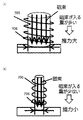
- FIG. 4 is a diagram for explaining the relationship between the coil shaft diameter and thrust in electromagnetic transfer
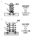
- FIG. 5 is a diagram for explaining the relationship between the coil shaft diameter and the inductance change rate related to detection in electromagnetic transfer.
- 6 to 8 are diagrams corresponding to the A-A' cross section of FIG. 2, showing other configuration examples of the sample transport apparatus.
- FIG. 9 is a top view showing an example of still another configuration of the sample transport device
- FIG. 10 is a cross-sectional view taken along line B-B' in FIG.
- a sample to be tested in the sample analysis system 1000 is collected and stored in a sample container 150 and handled.
- the sample container 150 is inserted into the container holder 100 manually by an operator or by an automatic insertion unit, transported through the system, and subjected to various processes such as pretreatment and analysis.
- One or more container holders 100 on which sample containers 150 containing samples are mounted are provided in the transport device 700, and each has a magnetic body 105 and a gripping portion 101 that supports the sample container 150. ing.
- the magnetic body 105 is provided near the bottom surface of each of the plurality of container holders 100 , and the container holder 100 is conveyed by the electromagnetic force acting on the magnetic body 105 .
- the magnetic body 105 is composed of, for example, a permanent magnet such as neodymium or ferrite, but it can also be composed of other magnets or magnetic bodies, and can be combined as appropriate.
- the container holder 100 having the magnetic material 105 slides on the carrier tile 120 .
- magnetic poles 707 and 707A composed of cylindrical coil shafts 705 and 705A and coils 706 wound around the outer circumferences of the coil shafts 705 and 705A are provided below the conveying tile 120. Multiple are provided.
- the magnetic poles 707 and 707A constitute each of a plurality of detection points for detecting the position of the magnetic body 105.
- FIG. Moreover, a plurality of transport paths are provided above the magnetic pole 707 so as to cover the magnetic pole 707 . Details of the coil shafts 705, 705A and the coil 706 will be described later.
- the transport tile 120 is composed of a flat surface with a small frictional force, and the container holder 100 slides on its upper surface.
- a plurality of magnetic poles 707 provided inside the device detect the position of the magnetic body 105 and also transport the magnetic body 105, that is, transport the sample.
- a driving unit 708 is connected to the magnetic pole 707 to apply a predetermined voltage to the magnetic pole 707 to cause a predetermined current to flow through the coil 706 .
- a magnetic pole 707 to which a voltage is applied by the drive unit 708 acts as an electromagnet and attracts the magnetic material 105 of the container holder 100 on the transfer tile 120 . After the container holder 100 is attracted by the magnetic pole 707, the application of the voltage to the magnetic pole 707 from the drive unit 708 is stopped, and the voltage is applied from the drive unit 708 to the different magnetic pole 707 adjacent to the magnetic pole 707 in the same manner as described above. The magnetic material 105 of the container holder 100 is attracted to the adjacent magnetic poles 707 .
- the sample accommodated in the sample container 150 mounted on the container holder 100 provided with the magnetic material 105 is transported to the destination.
- the calculation unit 709 calculates the current to be applied to each coil 706 using various information such as position information, speed information, and weight information of the container holder 100 and outputs command signals to each drive unit 708 .
- the drive unit 708 applies a voltage to the corresponding coil 706 based on the command signal.
- the detection unit 710 is configured to indirectly determine the position of the sample container 150 by detecting the current flowing through the coil 706 of the magnetic pole 707 and its flow method to determine the position of the magnetic body 105 . This principle is as follows.
- the coil shaft 705 is made of a magnetic material, and the magnetic flux passing through the coil shaft 705 has the property that it becomes difficult to pass as the magnetic flux increases.
- a voltage is applied to the coil 706 to flow a current, magnetic flux generated by the current is generated in the coil shaft 705 . Therefore, magnetic flux generated by the magnetic body 105 and magnetic flux generated by the current flowing through the coil 706 are generated in the coil shaft 705 .
- the inductance changes depending on the magnitude of the magnetic flux generated in the coil shaft 705 . That is, the inductance of the coil 706 changes depending on the magnitude of the magnetic flux of the magnetic body 105 . This means that the inductance of coil 706 changes depending on the position of magnetic body 105 .
- the inductance L can be calculated by detecting the current flowing through the coil 706 and how it flows. That is, by detecting the inductance L of the coil 706, which varies depending on the position of the magnetic body 105, the position of the magnetic body 105 that affects the inductance L can be obtained.
- the container holder 100 can be transferred over a short distance of several meters to a long distance of several tens of meters. At least one or more, preferably a plurality of transport tiles 120 are arranged.
- Magnetic poles 707 are arranged in a grid pattern in the conveying device 700, and an electromagnetic force is generated by applying a current to the coils 706 of the arranged magnetic poles 707.
- the container holder 100 is transported using the force of adsorption, and the required characteristics of the plurality of magnetic poles in the transporting device 700 differ depending on the arrangement position within the transporting device 700 .
- the coefficient of static friction that works at the moment an object starts moving is greater than the coefficient of dynamic friction that works while the object is moving. That is, the magnetic pole directly below the position where the container holder 100 does not stop, that is, the magnetic pole that generates the driving force for starting the movement of the container holder 100 from the position where the container holder 100 stops, has a greater driving force than the magnetic pole directly below the position where the container holder 100 stops. power is required.
- the magnetic pole immediately below the position where the container holder 100 stops is required to have a high stopping position accuracy of the container holder 100 in order to ensure the robustness when the container holder 100 operates next and interfere with the adjacent container holder 100. be done.
- the “position where the container holder 100 stops” is a position where it is required to change the conveying direction of the container holder 100. In FIG. The positions of the parts correspond.
- the “position where the container holder 100 does not stop” is a position where it is not required to change the conveying direction of the container holder 100.
- the position adjacent to the central portion corresponds to the position where a large thrust force is required to start moving the container holder 100 stopped at the stop position.
- the magnetic poles for conveying also serve to detect the position of the container holder 100 at the same time as driving the container holder 100 .
- driving force and position detection accuracy there is a trade-off between driving force and position detection accuracy.
- (a) is the case where the diameter of the coil shaft 705 is large. Since the amount of magnetic flux entering the coil shaft 705 is large, the electromagnetic force to the magnetic body 105 on the container holder 100 side, that is, the thrust force can be increased.
- (b) is a case where the diameter of the coil shaft 705 is small, and the amount of magnetic flux entering the coil shaft 705 is small, so the thrust becomes small.
- (a) is a case where the diameter of the coil shaft 705 is small, and since the magnetic flux of the coil shaft 705 is easily saturated, the rate of change in inductance is large.
- (b) is a case where the diameter of the coil shaft 705 is large, and since the magnetic flux of the coil shaft 705 is difficult to saturate, the inductance change rate is small.
- Magnetic permeability ⁇ is the ease of magnetization of a substance, and is a numerical representation of the ease of magnetization of a substance.
- the magnetic permeability of the coil shaft 705 of the magnetic pole 707 at the stop position is made smaller than the magnetic permeability of the coil shaft 705A of the magnetic pole 707A at the non-stop position.
- the coil 706 of the magnetic pole 707 at the stop position and the coil 706 of the magnetic pole 707A at the non-stop position have the same specifications, but they do not have to be the same, and various specifications such as the material, the number of turns N, and the length l. can be different.
- Examples of materials suitably selected for the coil shafts 705 and 705A having different magnetic permeability ⁇ include iron and aluminum having a smaller magnetic permeability ⁇ than iron. Also, with iron, the amount of carbon contained can be increased or decreased (magnetic permeability is greater than less).
- the difference between the magnetic pole 707 immediately below the position where the container holder 100 does not stop and the magnetic pole 707 immediately below where the container holder 100 stops is not limited to the magnetic permeability ⁇ of the coil shafts 705 and 705A as shown in FIGS. . Examples of other forms will be described below with reference to FIGS. 6 to 8.
- FIG. 1 The difference between the magnetic pole 707 immediately below the position where the container holder 100 does not stop and the magnetic pole 707 immediately below where the container holder 100 stops is not limited to the magnetic permeability ⁇ of the coil shafts 705 and 705A as shown in FIGS. . Examples of other forms will be described below with reference to FIGS. 6 to 8.
- the number of turns N of the coils 706 and 706B can be changed between the magnetic pole 707 directly below the position where the container holder 100 does not stop and the magnetic pole 707B directly below where the container holder 100 stops.
- the inductance L is proportional to the square of the total number of turns N of the coil 706, the greater the number of turns N of the coil 706, the smaller the inductance change rate.
- the number of turns of the coil 706 of the magnetic pole 707 at the stop position is made smaller than the number of turns of the coil 706B of the magnetic pole 707B at the non-stop position.
- the coil shaft 705 of the magnetic pole 707 at the stop position and the coil shaft 705 of the magnetic pole 707B at the non-stop position have the same specifications, but they do not have to be the same.
- one or more of various specifications such as material, cross-sectional area, and length may be different.
- the cross-sectional areas S of the coils 706 and 706C can be different.
- the inner diameters of the coils 706, 706C are the same as the outer diameters of the coil shafts 705, 705C.
- the larger the diameter of the coil shaft the smaller the magnetic resistance and the larger the amount of magnetic flux that enters.
- the diameter of the coil shaft is small, the magnetic resistance increases and the amount of magnetic flux entering decreases. That is, the larger the cross-sectional area S of the coil 706, the smaller the inductance change rate.
- the cross-sectional areas of the coil shaft 705 and the coil 706 of the magnetic pole 707 at the stop position are made narrower than the cross-sectional areas of the coil shaft 705C and the coil 706C of the magnetic pole 707C at the non-stop position.
- the thickness of the wire that constitutes the coil 706 can be changed.
- the length l of the coils 706D, 706E and the coil shafts 705D, 705E can be changed.
- the inductance L is inversely proportional to the length l of the coil 706, the shorter the coil length l, the smaller the inductance change rate.
- the lengths of the coil shaft 705E and the coil 706E that constitute the magnetic pole 707E at the non-stop position are made shorter than the lengths of the coil shaft 705D and coil 706D of the magnetic pole 707D at the stop position.
- any one of "the magnetic permeability ⁇ of the coil shaft 705, the winding N of the coil 706, the cross-sectional area S of the coil 706, and the length l of the coil 706" A form using magnetic poles with two types of one specification is exemplified. This is because the smaller the number of specifications, the easier the manufacturing, the higher the manufacturing cost, and the lower the power consumption. can.
- 3, 5, 6, and 7 can be appropriately mixed, such as changing "the magnetic permeability ⁇ of the coil shaft 705 and the winding N of the coil 706," and three or more specifications can be changed. can.
- the magnetic poles more specialized for position detection and the magnetic poles suitable for driving can be arranged at suitable locations respectively.
- FIG. 9 An example of a magnetic pole arrangement suitable for the case where the conveying devices 700 are adjacent will be described with reference to FIGS. 9 and 10.
- FIG. 9 An example of a magnetic pole arrangement suitable for the case where the conveying devices 700 are adjacent will be described with reference to FIGS. 9 and 10.
- the end of the transport tile 120 is preferably yoke-shaped, which is provided at the end of the coil shaft 705 opposite to the transport tile 120 side, so that the thrust is weakened.
- the edge of the transport tile 120 that contacts another transport tile 120 is positioned at the end so that the container holder 100 does not stop. It is desirable that the magnetic pole 707F at the non-stop position, where the transport tile 120 of the other transport device 700 is located, is designed to emphasize the driving force compared to the magnetic pole 707G at the stop position.
- the magnetic permeability of the coil shaft 705F is made larger than that of the coil shaft 705G of the magnetic pole 707G at the stop position, Make the cross-sectional area of coil shaft 705F and coil 706F wider and narrower than the cross-sectional area of coil shaft 705G and coil 706G, or make coil shaft 705F and coil 706F shorter than coil shaft 705G and coil 706G. , or other specifications may be different, and is not particularly limited.
- the position adjacent to the central portion of the cross-shaped portion in the transfer tile 120 which is defined as "the position where the container holder 100 does not stop” in FIG. 2 and the like, the position adjacent to the central portion of the portions arranged in a cross shape in the transport tile 120 is defined as the "non-stop position of the container holder 100".
- Magnetic poles with the same specifications as the ends, or even different specifications can be arranged.
- the magnetic poles 707A, 707B, 707C, 707E, and 707G immediately below the position where the container holder 100 does not stop in the transport tile 120 and the container holder 100 stop. With the magnetic poles 707, 707D, 707G directly below the position where the Specifications are different.
- the magnetic permeability ⁇ of the coil shafts 705, 705A, the number of turns N of the coils 706, 706B, the cross-sectional area S of the coils 706, 706C, or the length l of the coils 706D, 706E are changed. It can be easily changed without changing many, and it is possible to achieve both stable transportation and suppression of increase in power consumption.
- the thrust is expected to be low at the end.
- the magnetic poles 707F having a large value, the container holder 100 can be conveyed stably and quickly.
Abstract
Description
V=-dφ/dt (1)
との関係で表される。ここで、φは磁束、tは時間である。電圧Vは単位時間当たりの磁束の変化量で表される。
dI/dt=(1/L)×(dφ/dt) (2)
との関係が成立する。これら式(1)および式(2)から
dI/dt=-V/L (3)
との関係が成立する。
なお、本発明は上記の実施例に限られず、種々の変形、応用が可能なものである。上述した実施例は本発明を分かりやすく説明するために詳細に説明したものであり、必ずしも説明した全ての構成を備えるものに限定されない。
101…把持部
105…磁性体
120…搬送タイル
150…検体容器
700,700A,700B,700C…搬送装置
705,705A,705C,705D,705E,705F,705G…コイルシャフト
706,706B,706C,706D,706E,706F,706G…コイル
707,707A,707B,707C,707D,707E,707F,707G…磁極
708…駆動部
709…演算部
710…検出部
800…分析装置
900…制御用コンピュータ
1000…検体分析システム
Claims (8)
- 検体が収容された検体容器を搬送する検体搬送装置であって、
磁性体を有しており、前記検体容器を把持するホルダと、
コイルシャフトおよび前記コイルシャフトの外周側に巻かれているコイルを有する磁極を複数有する搬送タイルと、を備え、
前記搬送タイル内において前記ホルダが停止しない位置の直下の前記磁極と前記ホルダが停止する位置の直下の前記磁極とで、前記コイル、前記コイルシャフトのうちいずれか一方の仕様が異なる
ことを特徴とする検体搬送装置。 - 請求項1に記載の検体搬送装置において、
前記仕様として、前記コイルシャフトの透磁率を変えている
ことを特徴とする検体搬送装置。 - 請求項1に記載の検体搬送装置において、
前記仕様として、前記コイルの巻き数を変えている
ことを特徴とする検体搬送装置。 - 請求項1に記載の検体搬送装置において、
前記仕様として、前記コイルおよび前記コイルシャフトの断面積を変えている
ことを特徴とする検体搬送装置。 - 請求項1に記載の検体搬送装置において、
前記仕様として、前記コイルの長さを変えている
ことを特徴とする検体搬送装置。 - 請求項1に記載の検体搬送装置において、
前記搬送タイルを複数備える場合に、他の前記搬送タイルと接する前記搬送タイルの端部を前記ホルダが停止しない位置とし、他の箇所のうち1箇所以上を停止する位置とする
ことを特徴とする検体搬送装置。 - 請求項1に記載の検体搬送装置を備えた
ことを特徴とする検体分析システム。 - 磁性体を備えるホルダに保持された検体容器に収容された検体の搬送方法であって、
コイルシャフトおよび前記コイルシャフトの外周側に巻かれているコイルを有する磁極を複数有する搬送タイルを1枚以上並べ、
前記磁性体と前記磁極との相互作用によって前記ホルダを前記搬送タイル上を滑走させることで前記検体を搬送するにあたり、
前記ホルダが停止しない位置の直下の前記磁極と前記ホルダが停止する位置の直下の前記磁極とで、前記コイル、前記コイルシャフトのうちいずれか一方の仕様が異なるようにした
ことを特徴とする検体の搬送方法。
Priority Applications (3)
| Application Number | Priority Date | Filing Date | Title |
|---|---|---|---|
| JP2023520809A JPWO2022239377A1 (ja) | 2021-05-13 | 2022-02-28 | |
| EP22807084.3A EP4339141A1 (en) | 2021-05-13 | 2022-02-28 | Specimen conveyance device, specimen analysis system and specimen conveyance method |
| CN202280032583.9A CN117242352A (zh) | 2021-05-13 | 2022-02-28 | 检体输送装置和检体分析系统以及检体输送方法 |
Applications Claiming Priority (2)
| Application Number | Priority Date | Filing Date | Title |
|---|---|---|---|
| JP2021-081527 | 2021-05-13 | ||
| JP2021081527 | 2021-05-13 |
Publications (1)
| Publication Number | Publication Date |
|---|---|
| WO2022239377A1 true WO2022239377A1 (ja) | 2022-11-17 |
Family
ID=84029089
Family Applications (1)
| Application Number | Title | Priority Date | Filing Date |
|---|---|---|---|
| PCT/JP2022/008252 WO2022239377A1 (ja) | 2021-05-13 | 2022-02-28 | 検体搬送装置、および検体分析システム、並びに検体の搬送方法 |
Country Status (4)
| Country | Link |
|---|---|
| EP (1) | EP4339141A1 (ja) |
| JP (1) | JPWO2022239377A1 (ja) |
| CN (1) | CN117242352A (ja) |
| WO (1) | WO2022239377A1 (ja) |
Citations (5)
| Publication number | Priority date | Publication date | Assignee | Title |
|---|---|---|---|---|
| JPH04350023A (ja) * | 1990-08-08 | 1992-12-04 | Mitsubishi Heavy Ind Ltd | 搬送装置及び搬送用パレット |
| JPH06156730A (ja) * | 1992-11-13 | 1994-06-03 | Ebara Corp | 搬送装置 |
| JP2017077971A (ja) * | 2011-11-04 | 2017-04-27 | エフ.ホフマン−ラ ロシュ アーゲーF. Hoffmann−La Roche Aktiengesellschaft | 研究室試料配送システムおよび対応する動作方法 |
| JP2019505796A (ja) * | 2016-02-26 | 2019-02-28 | エフ.ホフマン−ラ ロシュ アーゲーF. Hoffmann−La Roche Aktiengesellschaft | タイル状の駆動表面を有する搬送装置 |
| WO2021065362A1 (ja) * | 2019-10-01 | 2021-04-08 | 株式会社日立ハイテク | 搬送装置、および分析システム |
-
2022
- 2022-02-28 WO PCT/JP2022/008252 patent/WO2022239377A1/ja active Application Filing
- 2022-02-28 JP JP2023520809A patent/JPWO2022239377A1/ja active Pending
- 2022-02-28 EP EP22807084.3A patent/EP4339141A1/en active Pending
- 2022-02-28 CN CN202280032583.9A patent/CN117242352A/zh active Pending
Patent Citations (5)
| Publication number | Priority date | Publication date | Assignee | Title |
|---|---|---|---|---|
| JPH04350023A (ja) * | 1990-08-08 | 1992-12-04 | Mitsubishi Heavy Ind Ltd | 搬送装置及び搬送用パレット |
| JPH06156730A (ja) * | 1992-11-13 | 1994-06-03 | Ebara Corp | 搬送装置 |
| JP2017077971A (ja) * | 2011-11-04 | 2017-04-27 | エフ.ホフマン−ラ ロシュ アーゲーF. Hoffmann−La Roche Aktiengesellschaft | 研究室試料配送システムおよび対応する動作方法 |
| JP2019505796A (ja) * | 2016-02-26 | 2019-02-28 | エフ.ホフマン−ラ ロシュ アーゲーF. Hoffmann−La Roche Aktiengesellschaft | タイル状の駆動表面を有する搬送装置 |
| WO2021065362A1 (ja) * | 2019-10-01 | 2021-04-08 | 株式会社日立ハイテク | 搬送装置、および分析システム |
Also Published As
| Publication number | Publication date |
|---|---|
| EP4339141A1 (en) | 2024-03-20 |
| CN117242352A (zh) | 2023-12-15 |
| JPWO2022239377A1 (ja) | 2022-11-17 |
Similar Documents
| Publication | Publication Date | Title |
|---|---|---|
| JP7325184B2 (ja) | 搬送装置、およびそれを備えた検体分析システム、検体前処理装置 | |
| JP7300281B2 (ja) | 搬送装置、およびそれを備えた検体分析システム、検体前処理装置、ならびに被搬送体の搬送方法 | |
| JP7319096B2 (ja) | 搬送装置 | |
| WO2022239377A1 (ja) | 検体搬送装置、および検体分析システム、並びに検体の搬送方法 | |
| CN115667107A (zh) | 运送装置以及分析系统 | |
| WO2022079976A1 (ja) | 検体容器キャリアおよび検体搬送装置 | |
| WO2020255538A1 (ja) | 搬送装置および搬送方法 | |
| WO2023026711A1 (ja) | 搬送装置、搬送装置を備えた検体分析システム、および、搬送装置を備えた検体前処理装置 | |
| WO2020183889A1 (ja) | 搬送装置、およびそれを備えた検体分析システム、検体前処理装置 | |
| US20230273229A1 (en) | Sample transport device, sample analysis system, and sample pretreatment device | |
| WO2023026777A1 (ja) | 搬送装置、搬送装置を備えた検体分析システム、および、搬送装置を備えた検体前処理装置 | |
| WO2023145174A1 (ja) | 搬送装置、および搬送方法 | |
| JP7315798B2 (ja) | 検体搬送装置および検体搬送用キャリア | |
| JP7480363B2 (ja) | 検体搬送システム、および検体の搬送方法 | |
| WO2021245990A1 (ja) | 搬送装置、および分析システム | |
| WO2023162340A1 (ja) | 搬送装置、および搬送方法 | |
| WO2023026622A1 (ja) | 検体搬送装置および検体搬送方法 |
Legal Events
| Date | Code | Title | Description |
|---|---|---|---|
| 121 | Ep: the epo has been informed by wipo that ep was designated in this application |
Ref document number: 22807084 Country of ref document: EP Kind code of ref document: A1 |
|
| WWE | Wipo information: entry into national phase |
Ref document number: 2023520809 Country of ref document: JP |
|
| WWE | Wipo information: entry into national phase |
Ref document number: 18560428 Country of ref document: US |
|
| WWE | Wipo information: entry into national phase |
Ref document number: 2022807084 Country of ref document: EP |
|
| NENP | Non-entry into the national phase |
Ref country code: DE |
|
| ENP | Entry into the national phase |
Ref document number: 2022807084 Country of ref document: EP Effective date: 20231213 |