WO2022239347A1 - 保持構造及び保持方法 - Google Patents
保持構造及び保持方法 Download PDFInfo
- Publication number
- WO2022239347A1 WO2022239347A1 PCT/JP2022/006153 JP2022006153W WO2022239347A1 WO 2022239347 A1 WO2022239347 A1 WO 2022239347A1 JP 2022006153 W JP2022006153 W JP 2022006153W WO 2022239347 A1 WO2022239347 A1 WO 2022239347A1
- Authority
- WO
- WIPO (PCT)
- Prior art keywords
- substrate
- holding
- holding structure
- imu
- board
- Prior art date
- Legal status (The legal status is an assumption and is not a legal conclusion. Google has not performed a legal analysis and makes no representation as to the accuracy of the status listed.)
- Ceased
Links
Images


Classifications
-
- H—ELECTRICITY
- H05—ELECTRIC TECHNIQUES NOT OTHERWISE PROVIDED FOR
- H05K—PRINTED CIRCUITS; CASINGS OR CONSTRUCTIONAL DETAILS OF ELECTRIC APPARATUS; MANUFACTURE OF ASSEMBLAGES OF ELECTRICAL COMPONENTS
- H05K7/00—Constructional details common to different types of electric apparatus
- H05K7/14—Mounting supporting structure in casing or on frame or rack
-
- G—PHYSICS
- G01—MEASURING; TESTING
- G01C—MEASURING DISTANCES, LEVELS OR BEARINGS; SURVEYING; NAVIGATION; GYROSCOPIC INSTRUMENTS; PHOTOGRAMMETRY OR VIDEOGRAMMETRY
- G01C19/00—Gyroscopes; Turn-sensitive devices using vibrating masses; Turn-sensitive devices without moving masses; Measuring angular rate using gyroscopic effects
- G01C19/56—Turn-sensitive devices using vibrating masses, e.g. vibratory angular rate sensors based on Coriolis forces
- G01C19/5783—Mountings or housings not specific to any of the devices covered by groups G01C19/5607 - G01C19/5719
-
- G—PHYSICS
- G03—PHOTOGRAPHY; CINEMATOGRAPHY; ANALOGOUS TECHNIQUES USING WAVES OTHER THAN OPTICAL WAVES; ELECTROGRAPHY; HOLOGRAPHY
- G03B—APPARATUS OR ARRANGEMENTS FOR TAKING PHOTOGRAPHS OR FOR PROJECTING OR VIEWING THEM; APPARATUS OR ARRANGEMENTS EMPLOYING ANALOGOUS TECHNIQUES USING WAVES OTHER THAN OPTICAL WAVES; ACCESSORIES THEREFOR
- G03B15/00—Special procedures for taking photographs; Apparatus therefor
-
- G—PHYSICS
- G03—PHOTOGRAPHY; CINEMATOGRAPHY; ANALOGOUS TECHNIQUES USING WAVES OTHER THAN OPTICAL WAVES; ELECTROGRAPHY; HOLOGRAPHY
- G03B—APPARATUS OR ARRANGEMENTS FOR TAKING PHOTOGRAPHS OR FOR PROJECTING OR VIEWING THEM; APPARATUS OR ARRANGEMENTS EMPLOYING ANALOGOUS TECHNIQUES USING WAVES OTHER THAN OPTICAL WAVES; ACCESSORIES THEREFOR
- G03B17/00—Details of cameras or camera bodies; Accessories therefor
-
- G—PHYSICS
- G03—PHOTOGRAPHY; CINEMATOGRAPHY; ANALOGOUS TECHNIQUES USING WAVES OTHER THAN OPTICAL WAVES; ELECTROGRAPHY; HOLOGRAPHY
- G03B—APPARATUS OR ARRANGEMENTS FOR TAKING PHOTOGRAPHS OR FOR PROJECTING OR VIEWING THEM; APPARATUS OR ARRANGEMENTS EMPLOYING ANALOGOUS TECHNIQUES USING WAVES OTHER THAN OPTICAL WAVES; ACCESSORIES THEREFOR
- G03B30/00—Camera modules comprising integrated lens units and imaging units, specially adapted for being embedded in other devices, e.g. mobile phones or vehicles
-
- H—ELECTRICITY
- H04—ELECTRIC COMMUNICATION TECHNIQUE
- H04N—PICTORIAL COMMUNICATION, e.g. TELEVISION
- H04N23/00—Cameras or camera modules comprising electronic image sensors; Control thereof
- H04N23/50—Constructional details
- H04N23/51—Housings
-
- H—ELECTRICITY
- H04—ELECTRIC COMMUNICATION TECHNIQUE
- H04N—PICTORIAL COMMUNICATION, e.g. TELEVISION
- H04N5/00—Details of television systems
- H04N5/222—Studio circuitry; Studio devices; Studio equipment
-
- H—ELECTRICITY
- H05—ELECTRIC TECHNIQUES NOT OTHERWISE PROVIDED FOR
- H05K—PRINTED CIRCUITS; CASINGS OR CONSTRUCTIONAL DETAILS OF ELECTRIC APPARATUS; MANUFACTURE OF ASSEMBLAGES OF ELECTRICAL COMPONENTS
- H05K7/00—Constructional details common to different types of electric apparatus
- H05K7/14—Mounting supporting structure in casing or on frame or rack
- H05K7/1417—Mounting supporting structure in casing or on frame or rack having securing means for mounting boards, plates or wiring boards
Definitions
- This technology relates to a holding structure and holding method applicable when installing an inertial sensor.
- Patent Document 1 discloses an anti-vibration system for inertial sensors.
- this vibration isolation system an elastomer member is arranged around the inertial sensor.
- elastomer member is arranged around the inertial sensor.
- an object of the present technology is to provide a holding structure and a holding method capable of improving the measurement accuracy of the inertial sensor.
- a holding structure for installing a substrate on which an inertial sensor is arranged on an object, and includes two or more connection structure portions.
- the two or more connection structures are configured at two or more locations on the substrate and connect the substrate to the object.
- each of the two or more connection structure portions is configured by an adhesive structure in which an adhesive material is provided between the object and the substrate that are arranged to be spaced apart from each other;
- One of the connecting structure portions is configured by a pressing structure that presses and fixes the substrate to the object, and the other is configured by the bonding structure.
- connection structure portions for connecting the substrate to the object are formed at two or more locations on the substrate.
- Each of the two or more connection structures is configured by a bonding structure in which a bonding material is provided between an object and a substrate that are spaced apart from each other.
- one of the two or more connection structures is configured by a pressing structure that presses and fixes the substrate to the object, and the other is configured by an adhesive structure. This makes it possible to improve the measurement accuracy of the inertial sensor.
- the pressing structure may include a structure for fixing the substrate to the object via a fastening member.
- the fastening member may be a screw.
- the pressing structure may include a structure for sandwiching and fixing the substrate between the objects.
- the object may have a first fixing portion and a second fixing portion that sandwich and fix the substrate.
- at least one of the first fixing portion and the second fixing portion may fix the substrate via an elastic body.
- the adhesive structure may include a structure in which the adhesive material is provided with reference to the position of the hole in a state where the insertion portion of the substrate is inserted into the hole of the object.
- the hole may be a through hole.
- the adhesive material may be provided so as to cover at least part of the opening of the hole.
- the adhesive material may be filled inside the holes.
- the adhesive structure may include a structure in which the adhesive material is provided with reference to the position of the hole in a state in which the insertion portion of the object is inserted into the hole of the substrate.
- Each of the two or more connecting structure portions may be configured by the bonding structure.
- One of the two or more connecting structure portions may be configured by the pressing structure, and the other may be configured by the bonding structure.
- the inertial sensor may be configured to include at least one of an acceleration sensor and an angular velocity sensor.
- the position of each of the two or more connection structures may be set with reference to the position of the inertial sensor on the substrate.
- the position of the inertial sensor may be set based on the position of each of the two or more connection structures.
- the inertial sensor may be arranged at the center of gravity of each position of the two or more connection structures.
- the holding structure is configured to set the substrate so as to rotate integrally with the rotating portion configured to be rotatable about a predetermined rotation axis that is the object. good too.
- an imaging section may be installed on the rotating section so as to rotate integrally with the rotating section.
- a holding method is a holding method for installing a substrate on which an inertial sensor is arranged on an object, wherein each of two or more portions of the substrate is arranged so as to be spaced apart from each other. and connecting to the object by an adhesive structure in which an adhesive material is provided between the object and the substrate.
- a holding method is a holding method for installing a substrate on which an inertial sensor is arranged on an object, wherein one of two or more locations of the substrate is attached to the object. connecting to the object by a pressing structure that presses and fixes the . Others of the two or more locations are connected to the object by an adhesive structure in which an adhesive material is provided between the object and the substrate that are spaced apart from each other.
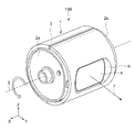
- FIG. 1 is a perspective view showing an appearance example of an imaging device
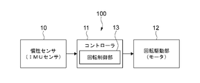
- FIG. 3 is a functional block diagram for explaining basic operations of the imaging device
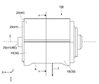
- FIG. FIG. 3 is a side view of the imaging device as seen from the positive direction side in the Z direction
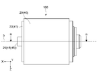
- FIG. 3 is a side view of the imaging device viewed from the negative direction side in the Y direction
- FIG. 5 is a cross-sectional view taken along line BB of FIG. 4
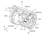
- It is a perspective view which shows the internal structure of an imaging device.
- FIG. 4 is a cross-sectional view taken along line AA of FIG. 3; It is a schematic diagram which shows the outline
- FIG. 1 is a perspective view showing an appearance example of an imaging device according to this embodiment. As shown in FIG. 1, the imaging device 100 has a substantially cylindrical shape. FIG. 1 shows the exterior so that the bottom 2a and the side 3 of the two bottoms 2 (2a and 2b) of the imaging device 100 can be seen.
- the depth direction (perpendicular to the bottom portion 2a) is defined as the X direction
- the horizontal direction is defined as the Y direction
- the vertical direction is defined as the Z direction.
- the positive direction and negative direction of the X direction shown in FIG. 1 may be referred to as the front direction and the back direction.
- the positive direction and negative direction of the Y direction may be described as the right direction and the left direction.
- the positive direction and negative direction of the Z direction may be described as upward direction and downward direction.
- the above expressions may be used to indicate the viewing direction of the imaging device 100 .
- the expression "viewing the imaging device 100 from the positive side of the X direction” means “viewing the imaging device 100 from the tip side of the arrow indicating the X axis".
- the orientation in which the imaging device 100 is used is not limited.
- the imaging device 100 has a rotating section 1 configured to be rotatable about a predetermined rotation axis.
- the rotating portion 1 has a bottom portion 2 (2a and 2b) and side portions 3, and is configured to be rotatable about a rotating shaft 5 passing through the center of the bottom portion 2 and extending in the X direction. be.
- the rotating part 1 is rotatable about the rotating shaft 5 in the clockwise or counterclockwise direction when viewed from the X direction.
- the direction of rotation of the rotating portion 1 is indicated by a thick arrow.
- the rotating section 1 can also function as a housing of the imaging device 100 .
- a side portion 3 of the rotating portion 1 is provided with a window portion 4 .
- a concave portion 6 is formed in the side portion 3 of the rotating portion 1 , and the window portion 4 is arranged on the bottom surface of the concave portion 6 .
- the window part 4 has a substantially rectangular shape when viewed from the front. The shape of the window part 4 is not limited.
- the window part 4 is configured as a transparent member. In the present disclosure, "transparency" includes not only complete transparency but also semi-transparency and colored transparency.
- a camera module 21 (see FIG. 5) is installed inside the rotating portion 1 at a position facing the window portion 4 .
- the camera module 21 is installed on the rotating part 1 so that the imaging direction 7 faces the outside of the rotating part 1 .
- the camera module 21 is installed such that the imaging direction 7 is perpendicular to the window 4 .
- the imaging direction 7 is the axial direction of the imaging optical axis of the camera module 21 .
- the camera module 21 corresponds to an embodiment of an imaging unit according to the present technology.
- the camera module 21 is installed on the rotating section 1 so as to rotate integrally with the rotating section 1 . Therefore, the imaging direction of the camera module 21 changes according to the rotation of the rotating section 1 . For example, by controlling the rotation of the rotating portion 1, it is possible to arbitrarily set the imaging direction of the camera module 21 over the entire circumference of 360 degrees with the rotation axis 5 as the center.
- FIG. 2 is a functional block diagram for explaining the basic operation of the imaging device 100. As shown in FIG. As shown in FIG. 2 , the imaging device 100 has an inertial sensor 10 , a controller 11 and a rotation drive section 12 .
- the inertial sensor 10 is a sensor capable of measuring inertial force.
- the inertial sensor 10 is configured to include at least one of an acceleration sensor and an angular velocity sensor.
- an IMU (Inertial Measurement Unit) sensor is used as the inertial sensor 10 .
- IMU sensors are also called inertial measurement units.
- the IMU sensor is capable of detecting (sensing) the acceleration and angular velocity of the imaging device 100 .
- the IMU sensor can detect the acceleration and angular velocity of the imaging device 100 with respect to, for example, three mutually orthogonal axes.
- the inertial sensor 10 only an acceleration sensor may be used, or only an angular velocity sensor may be used. Any configuration may be adopted as a specific configuration of the inertial sensor 10 .
- the controller 11 has hardware necessary for configuring a computer, such as a CPU, ROM, RAM, and HDD.
- a computer such as a CPU, ROM, RAM, and HDD.
- the CPU loads a program according to the present technology prerecorded in the ROM or the like into the RAM and executes the program, thereby executing the processing related to the rotation control and the like according to the present technology.
- a PLD such as FPGA or a device such as ASIC may be used.
- Any computer such as a PC (Personal Computer) may function as the controller 11 .
- the rotation control unit 13 as a functional block is configured by the CPU executing a predetermined program.
- dedicated hardware such as an IC (integrated circuit) may be used to implement the functional blocks.
- Programs are installed, for example, via various recording media. Alternatively, program installation may be performed via the Internet or the like.
- the type of recording medium on which the program is recorded is not limited, and any computer-readable recording medium may be used.
- any computer-readable non-transitory storage medium may be used.
- the controller 11 is typically configured inside the imaging device 100 .
- the controller 11 is not limited to this, and the controller 11 may be configured outside the imaging device 100 and connected to the inertial sensor 10, the rotation driving section 12, and the like so as to be communicable.
- the rotation driving section 12 rotates the rotating section 1 .
- a motor 16 (see FIG. 5) is used as the rotation drive unit 12 .
- the motor 16 is connected to the bottom portion 2b of the rotating portion 1 opposite to the bottom portion 2a.
- a specific configuration of the motor 16 is not limited. Also, a device other than the motor 16 may be used as the rotation drive unit 12 .
- the rotation control section 13 controls rotation of the rotating section 1 based on the detection result of the inertial sensor 10 .
- an operator (user) or the like of the imaging device 100 inputs an operation for controlling the imaging direction of the camera module 21 .
- the rotation control unit 13 controls the imaging direction 7 of the camera module 21 according to the operator's operation.
- the rotation control unit 13 controls the rotation operation of the rotation driving unit 12 based on the detection result (sensing result) of the inertia sensor 10 . This makes it possible to control the rotation of the rotating section 1 with high accuracy, and to control the imaging direction 7 of the camera module 21 with high accuracy.
- the imaging device 100 can be mounted on a moving object such as a drone. Based on the detection result of the inertial sensor 10, it is also possible to acquire information about the position and orientation of the imaging device 100 (camera module 21), and high-precision imaging by the imaging device 100 becomes possible. As a result, it becomes possible to capture a high-quality image.
- a specific algorithm for rotation control by the rotation control unit 13 is not limited.
- FIG. 3 is a side view of the imaging device 100 viewed from the positive side in the Z direction.
- FIG. 4 is a side view of the imaging device 100 viewed from the negative direction side in the Y direction.
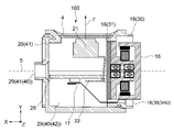
- 5 is a cross-sectional view taken along line BB of FIG. 4.
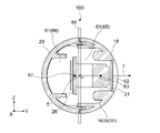
- FIG. 6 is a perspective view showing the internal configuration of the imaging device 100. As shown in FIG. FIG. 6 is a perspective view of the front holder 18 viewed from the inside. 7 is a cross-sectional view taken along line AA of FIG. 3.
- FIG. 6 is a perspective view of the front holder 18 viewed from the inside.
- the imaging device 100 includes a window portion 4, a motor 16, a motor flexible board 17, a front holder 18, a camera module 21, a camera flexible board 22, an IMU board 26, and board screws 27. , and a rear holder 29 .
- the front holder 18 can function as a housing for the imaging device 100 .
- the front holder 18 has a semi-cylindrical portion 30 and a bottom portion 31 .
- the semi-cylindrical portion 30 and the bottom portion 31 are made of, for example, rigid material.
- various members of the imaging device 100 are protected from external impact.
- the specific material and shape of the front holder 18 are not limited.
- the semi-cylindrical portion 30 has a shape approximately equal to one of the two halves of a cylinder (that is, a hollow cylinder) divided by a plane including the central axis of the cylinder. That is, as shown in FIG. 6, the semi-cylindrical portion 30 has a shape of a cylinder cut in half. The semi-cylindrical portion 30 is arranged such that the central axis of the cylinder coincides with the rotation axis 5 .
- the semi-cylindrical portion 30 has an inner surface 32 on the rotating shaft 5 side and an outer surface 33 on the opposite side of the inner surface 32 .
- the semi-cylindrical portion 30 also has two semi-ring-shaped arc surfaces 34 (34a and 34b) facing each other along the X direction.
- an internal space 61 is formed on the inner surface 32 side of the semi-cylindrical portion 30 .
- the inner surface 32 of the semi-cylindrical portion 30 is provided with a mechanism for holding various members such as the camera module 21 and the IMU board 26 arranged in the internal space 61 .
- the bottom portion 31 has a substantially disk shape.
- the bottom portion 31 has a circumferential portion of which the bottom portion 31 has a half circumferential portion along the inner surface 32 of the semi-cylindrical portion 30 and further inside than the arc surface 34b on the negative direction side in the X direction (that is, X on the positive side of the direction).
- a motor 16 is fixed to the bottom portion 31 .
- the motor 16 is fixed to the bottom 31, for example by screwing, gluing or press-fitting.
- the inside of the motor 16 may be attached directly to the front holder 18 .
- the fixing method of the motor 16 is not limited.
- the rear holder 29 can function as a housing of the imaging device 100 together with the front holder 18 .
- the rear holder 29 has a semi-cylindrical portion 40 and a bottom portion 41 .
- the semi-cylindrical portion 40 and the bottom portion 41 are made of, for example, rigid material. Of course, specific materials and shapes are not limited.
- the semi-cylindrical portion 40 of the rear holder 29 has substantially the same shape as the semi-cylindrical portion 30 of the front holder 18 .
- the bottom portion 41 of the rear holder 29 also has substantially the same shape as the bottom portion 31 of the front holder 18 .
- On the inner surface 42 of the semi-cylindrical portion 40 a mechanism for holding various members of the imaging device 100 is configured, similarly to the inner surface 32 of the semi-cylindrical portion 30 of the front holder 18. As shown in FIG.
- a cylindrical portion 46 is formed in the bottom portion 41 . As shown in FIG. 3 and the like, the cylindrical portion 46 is configured to protrude from the bottom portion 41 in the positive direction of the X direction. A circular opening is formed at the tip of the cylindrical portion 46 .
- the bottom portion 41 is configured such that the half circumference portion of the circumference portion of the bottom portion 41 is along the inner surface 42 of the semi-cylindrical portion 40 . Also, the bottom portion 41 is configured at a position substantially equal to the end portion of the semi-cylindrical portion 40 (the portion on the most positive side in the X direction) when viewed from the Y direction.
- the portion below the position of the rotating shaft 5 is the semi-cylindrical portion 30 of the front holder 18. As shown in FIG. A semi-cylindrical portion 40 of the rear holder 29 is formed above the position of the rotating shaft 5 .
- the front holder 18 is arranged on the most positive side in the Y direction of the imaging device 100 .
- the rear holder 29 is arranged on the most negative side in the Y direction.
- other members are arranged in the internal space 61 inside the front holder 18 and the rear holder 29 . That is, by fitting the front holder 18 and the rear holder 29 together, various members are held inside the front holder 18 and the rear holder 29, and the imaging device 100 is assembled as shown in FIG.
- the semi-cylindrical portion 30 of the front holder 18 and the semi-cylindrical portion 40 of the rear holder 29 constitute the side portion 3 shown in FIG.
- the bottom portion 31 of the front holder 18 constitutes the bottom portion 2b
- the bottom portion 41 of the rear holder 29 constitutes the bottom portion 2a. That is, the front holder 18 and the rear holder 29 constitute the entire rotating portion 1 shown in FIG.
- the front holder 18 and the rear holder 29 correspond to one embodiment of the rotating part according to the present technology.
- the camera module 21 performs imaging of the outside of the imaging device 100 .
- Any camera may be used as the camera module 21 .
- a digital camera capable of capturing still images or moving images, an infrared camera, or the like is used.
- a camera having a distance measuring function such as a ToF (Time Of Flight) camera, stereo camera, or monocular camera, may be used.
- the camera module 21 has various mechanisms for imaging such as a lens system.
- the camera module 21 corresponds to an embodiment of an imaging unit according to the present technology. A specific shape of the camera module 21 is not limited.
- the camera module 21 rotates integrally with the front holder 18 and the rear holder 29 according to the rotation of the front holder 18 and the rear holder 29 . Further, the camera module 21 changes the imaging direction 7 according to the rotation of the front holder 18 and the rear holder 29 .
- the camera flexible board 22 is a board for driving the camera module 21 .
- the camera flexible board 22 is connected to the IMU board 26 .
- the camera flexible substrate 22 has a rectangular shape and can be bent. One end of the camera flexible board 22 is connected to the camera module 21 . The other end of the camera flexible board 22 is connected to the IMU board 26 .
- the camera flexible substrate 22 is folded in three along the Z direction and connected.
- the camera flexible board 22 in a bent state has a substantially U shape when viewed from the Z direction.
- the operation of the camera module 21 is controlled by the controller 11 . Power is supplied, control signals are output, and the like are performed via the camera flexible substrate 22 .
- the method of connecting the camera module 21 and the IMU board 26 is not limited, and any method can be adopted.
- the camera module 21 and the IMU board 26 may be connected by a harness or the like.
- a motor 16 rotates the front holder 18 .
- a power source (not shown) is connected to the motor 16, and the motor 16 is driven by power supplied from the power source.
- the method of driving the motor 16 is not limited, and any method may be adopted.
- the front holder 18 and the rear holder 29 rotate integrally.
- each member constituting the imaging device 100, such as the IMU board 26, rotates together.
- the motor 16 is fixed outside the imaging device 100 .
- the motor 16 is fixed to, for example, a moving body on which the imaging device 100 is mounted.
- the imaging device 100 rotates relative to the moving object.
- rotation of the imaging device 100 is realized.
- the motor flexible board 17 is a board for driving the motor 16 .
- the motor flexible substrate 17 can be bent. As shown in FIG. 5 , one end of the motor flexible board 17 is connected to the motor 16 . The other end is connected to the surface of the IMU board 26 on the negative direction side in the Y direction (the surface not facing the camera module 21). In this embodiment, the operation of the motor 16 is controlled by the rotation control section 13 of the controller 11 . Power supply, control signal output, and the like are performed via the motor flexible substrate 17 .
- the method of connecting the motor 16 and the IMU board 26 is not limited, and any method can be adopted. For example, the motor 16 and the IMU board 26 may be connected by a harness or the like.
- an IMU sensor 60 is arranged on the IMU board 26 .
- the IMU board 26 is a board having a substantially rectangular plate shape.
- the IMU board 26 represents one embodiment of a board according to the present technology.
- each of the upper right corner and the lower right corner of the IMU board 26 is provided with a protrusion 55 protruding in the negative direction in the X direction.
- the protrusion 55 is provided to be inserted into the front holder 18 .
- a through hole 56 is formed near the upper left corner.
- the IMU board 26 is screwed to the front holder 18 through the through holes 56 .
- the front holder 18 is provided with a protrusion 57 at a position extending to the through hole 56 in the Y direction.
- the convex portion 57 is provided with a screw hole.
- the board screw 27 passes through the through hole 56 and is fitted into the screw hole formed in the projection 57 .
- the IMU board 26 is thereby screwed.
- a screw having a head and a screw portion is used as the board screw 27 .
- the specific material and shape of the board screw 27 are not limited.
- a through hole 58 is formed in the bottom portion 31 of the front holder 18 at a position corresponding to the convex portion 55 of the IMU board 26 . That is, two through holes 58 are formed in the bottom portion 31 . A projection 55 is inserted into each through hole 58 . Furthermore, the IMU board 26 is adhered to the front holder 18 by providing an adhesive 59 at the insertion position.
- the IMU board 26 is connected to the front holder 18 by screwing at one location and bonding at two locations.
- an IMU sensor 60 is arranged on the surface of the IMU board 26 on the negative side in the Y direction (the surface opposite to the camera module 21).
- the IMU sensor 60 corresponds to one embodiment of an inertial sensor according to the present technology.
- the camera flexible board 22 and the motor flexible board 17 (not shown) are connected.
- the specific configuration of the IMU board 26 is not limited. For example, when the controller 11 is provided on the IMU board 26 , hardware such as CPU, ROM, RAM, and HDD may be arranged on the IMU board 26 .
- the camera module 21 is installed on the positive direction side of the imaging device 100 in the Y direction.
- the IMU board 26 is installed near the rotating shaft 5 on the negative direction side of the rotating shaft 5 in the Y direction.
- the IMU board 26 and the camera module 21 are arranged so as to be separated from each other, and a space is formed between the IMU board 26 and the camera module 21 .
- the IMU board 26 and the camera module 21 are arranged to face each other with the rotating shaft 5 interposed therebetween.
- the front holder 18 and the rear holder 29 have an internal space 61 in which the rotating shaft 5 is arranged.
- the IMU board 26 divides the internal space 61 into a first divided space including the center of gravity of the camera module 21 and a first divided space including the center of gravity of the camera module 21 by a plane that is perpendicular to the perpendicular from the center of gravity of the camera module 21 to the rotation axis 5 and includes the rotation axis 5 .
- it is divided into a second divided space that does not include the center of gravity, it is installed in the front holder 18 so that the center of gravity is included in the second divided space.
- the internal space 61 is a space surrounded by the front holder 18 and the rear holder 29 .
- an internal space 61 is formed as a substantially cylindrical space surrounded by the front holder 18 and the rear holder 29 .
- the rotary shaft 5 is arranged inside the internal space 61 .
- the center of gravity 62 of the camera module 21 is the mass center of gravity of the camera module 21 (that is, the center of gravity considering the density).
- the center of gravity 62 of the camera module 21 is indicated by a black square.
- a perpendicular line 63 from the center of gravity 62 of the camera module 21 to the rotation axis 5 passes through the center of gravity 62 of the camera module 21 and forms a straight line parallel to the Y-axis.
- the vertical line 63 is indicated by a solid line.
- a plane orthogonal to the perpendicular 63 and containing the rotation axis 5 is a plane orthogonal to the Y-axis and containing the rotation axis 5 (parallel to the Z-axis). Therefore, the plane includes the rotation axis 5 and is parallel to the XZ plane.
- This plane is hereinafter referred to as a dividing plane 64 .
- the dividing plane 64 is schematically illustrated as a vertically long rectangle.
- the dividing plane 64 divides the internal space 61 into two spaces. That is, as shown in FIG. 7, the internal space 61 is divided into a space on the right side of the dividing plane 64 and a space on the left side.
- the right space contains the center of gravity of the camera module 21 . That is, the right space corresponds to the first divided space 65 including the center of gravity of the camera module 21 . Also, the center of gravity of the camera module 21 is not included in the left space. That is, the left space corresponds to the second divided space 66 that does not include the center of gravity of the camera module 21 .
- the IMU board 26 When the internal space 61 is divided in this way, the IMU board 26 is installed in the front holder 18 so that the center of gravity is included in the second divided space 66 .
- the center of gravity of IMU board 26 is also the center of mass of IMU board 26 .
- the center of gravity 67 of the IMU board 26 is indicated by a black square. As shown in FIG. 7, the center of gravity 67 of the IMU board 26 is included in the second partitioned space 66 .
- the center of gravity of the IMU board 26 and the center of gravity of the camera module 21 are located in different spaces (opposite sides).
- the center of gravity of mass is contained in mutually different spaces, but the positional center of gravity is contained in the same space. may be adopted.
- the camera module 21 is installed so as to be included in the first divided space 65 .
- the IMU board 26 is installed so as to be included in the second divided space 66 . That is, not only the center of gravity 62 of the camera module 21 but the entire camera module 21 is installed so as to be included in the first divided space 65 . Also, not only the center of gravity 67 of the IMU board 26 but the entire IMU board 26 is installed so as to be included in the second divided space 66 . As shown in FIG. 7 , in this embodiment, the entire camera module 21 is included in the first divided space 65 and the entire IMU board 26 is also included in the second divided space 66 .
- an arrangement configuration may be adopted in which only the center of gravity of the camera module 21 is included in the first divided space 65 and the entire camera module 21 is not included in the first divided space 65 .
- the center of gravity 62 is located in the first divided space 65. Therefore, such an arrangement configuration is possible.
- the IMU board 26 is the same applies to the IMU board 26 as well.
- the IMU board 26 is arranged in a direction perpendicular to the imaging direction 7 of the camera module 21 . That is, the board surface of the IMU board 26 is arranged in a direction orthogonal to the imaging direction 7 . As shown in FIG. 7, the imaging direction 7 is parallel to the Y-axis. Also, the surface of the IMU board 26 is arranged parallel to the XZ plane. That is, the imaging direction 7 and the plane of the IMU board 26 are orthogonal. Of course, the orientation of the IMU board 26 is not limited. For example, the surface of the IMU board 26 may be arranged obliquely (not parallel) to the XZ plane.
- the IMU board 26 and the camera module 21 are arranged in mutually different spaces (the first divided space 65 and the second divided space 66). As a result, the center of gravity of the imaging apparatus 100 as a whole is positioned near the rotation axis 5 .
- the IMU board 26 and camera module 21 are members having a certain amount of mass. When these are arranged in the same space (for example, when the camera module 21 is arranged on the IMU board 26, etc.), the mass will be biased with respect to the one space. That is, the center of gravity of the imaging apparatus 100 as a whole is positioned away from the rotation axis 5 (on one side of the space). When the center of gravity of the imaging device 100 as a whole is away from the rotation axis 5, the torque required to rotate the imaging device 100 increases. That is, the power required by the motor 16 increases. Therefore, a load is applied to the motor 16, and the amount of heat generated from the motor 16 increases.
- the center of gravity of the imaging apparatus 100 as a whole is positioned near the rotation axis 5, so the torque required for rotation is small, and heat generation by the motor 16 can be suppressed. This makes it possible to suppress heat transfer to the IMU board 26 and the like. Furthermore, since the required output of the motor 16 is reduced, it is possible to reduce the size of the entire imaging apparatus 100 including the motor 16 . Moreover, it is possible to suppress power consumption during rotation. Further, since the center of gravity is adjusted using the arrangement of the IMU board 26 and the camera module 21, no other mechanism for adjusting the center of gravity is required, and the weight of the imaging device 100 is reduced.
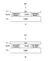
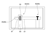
- FIG. 8 is a schematic diagram showing an outline of a holding structure 200 according to the present technology.
- the holding structure 200 is a structure for installing the substrate 81 on which the inertial sensor 10 is arranged on the object 80 .
- the holding structure 200 is configured at two or more locations on the substrate 81 and comprises two or more connection structures 82 for connecting the substrate 81 to the object 80 .
- 8A and B show two connection structures 82 configured at two locations on the substrate 81, three or more connection structures 82 may be configured at three or more locations on the substrate 81. 8 to 15, illustration of the inertial sensor 10 arranged on the substrate 81 is omitted.
- each of the two or more connecting structure portions 82 is configured by an adhesive structure 83.
- the adhesive structure 83 is a structure in which an adhesive material is provided between the object 80 and the substrate 81 that are spaced apart from each other.
- one of the two or more connection structures 82 is configured by the pressing structure 84 . Others are composed of the adhesive structure 83 .
- the pressing structure 84 is a structure that presses and fixes the substrate 81 to the object 80 .
- connection structures 82 are not limited to the examples shown in FIGS. 8A and 8B, and any number of connection structures 82 greater than or equal to two, such as three or four, may be configured. Also, all of the connecting structure portions 82 may be the bonding structure 83 , or one may be the pressing structure 84 and all of the others may be the bonding structure 83 .
- the bonding structure 83 and the pressing structure 84 can be configured in the following combinations, for example.
- connection structures 82 When there are two connecting structure portions 82 There are two bonding structures 83 One bonding structure 83 and one pressing structure 84 (2) When there are three connecting structure portions 82 There are three bonding structures 83 Two bonding structures 83 and one pressing structure 84 (3) When there are four connection structures 82 Four bonding structures 83 Three bonding structures 83 and one pressing structure 84 That is, two or more connection structures 82 are configured, of which at most one is a pressing structure 84 and all others are bonding structures 83 . It should be noted that when the bonding structure 83 is configured at a plurality of locations, each bonding structure 83 may have a different structure and shape.
- the substrate 81 is connected to the object 80 by the bonding structure 83 or the pressing structure 84 . That is, installation of the substrate 81 with respect to the object 80 is realized.
- the IMU board 26 is screwed to the projection 57 of the front holder 18 .
- This realizes a pressing structure 84 that presses and fixes the IMU board 26 to the front holder 18 .
- the pressing structure 84 a structure is adopted in which the IMU board 26 is fixed to the front holder 18 via the board screw 27 (fastening member).
- the projections 55 of the IMU board 26 are inserted into the two through holes 58 formed in the bottom portion 31 of the front holder 18 and adhered with the adhesive 59 .
- a bonding structure 83 is realized in which the bonding material is provided between the front holder 18 and the IMU substrate 26 that are spaced apart from each other.
- an adhesive material is provided with the position of the through-hole 58 as a reference in a state in which the convex portion 55 (insertion portion) of the IMU substrate 26 is inserted into the through-hole 58 of the front holder 18. structure is adopted.
- the holding structure 200 comprises three connection structures 82 arranged at three locations on the IMU board 26 .
- one connection structure portion 82 is configured by the pressing structure 84 .
- the other two connecting structures 82 are constituted by adhesive structures 83 .
- the portion to which the IMU board 26 is connected such as the convex portion 57 and the bottom portion 31, is sometimes called a holder.
- the IMU board 26 is connected to the front holder 18 by being screwed at one location and adhered at two locations. Accordingly, three connection structure portions 82 are configured.
- the order of screwing and bonding the IMU board 26 is not limited.
- the adhesive may be applied after screwing.
- a method may be adopted in which the screwed portions are temporarily fixed, and the temporarily fixed portions are screwed after the adhesion is performed.
- screwing and bonding may be performed by any method.
- a bonding portion between the through hole 58 configured in the bottom portion 31 and the convex portion 55 of the IMU substrate 26 corresponds to an embodiment of the bonding structure according to the present technology.
- two adhesive structures 83 are configured in the imaging device 100 .
- the protrusion 55 is inserted into the through hole 58 so as to be spaced apart. That is, the projection 55 is positioned in the space (inside the hole) formed by the through hole 58, but is inserted so as not to contact the surface of the bottom 31 forming the through hole 58.
- An adhesive 59 is provided in the gap formed between the protrusion 55 and the through hole 58 and in the vicinity thereof.
- the protrusion 55 and the through hole 58 are bonded together by the adhesive 59 so as to bridge the spaced apart protrusion 55 and the through hole 58 .
- the adhesive 59 corresponds to one embodiment of the adhesive material according to the present technology.
- the bonding structure 83 is not limited to such.
- a portion where the convex portion 57 of the front holder 18 and the IMU board 26 are screwed corresponds to an embodiment of the pressing structure according to the present technology. That is, one pressing structure 84 is configured in the imaging device 100 .
- the pressing structure 84 is a structure for fixing the IMU board 26 to the front holder 18 via the board screws 27 .
- a through hole 56 is formed in the IMU board 26 , and the screw portion of the board screw 27 passes through the through hole 56 .
- the screw hole formed in the convex portion 57 extends, and the screw hole and the screw portion are fitted.
- the IMU board 26 is thereby screwed.
- the board screw 27 corresponds to one embodiment of the fastening member and the screw according to the present technology.
- the screwed IMU board 26 is sandwiched between the head of the board screw 27 and the projection 57 of the front holder 18 . That is, the head of the board screw 27 presses and fixes the IMU board 26 to the front holder 18 .
- the pressing structure 84 is not limited to such a structure. That is, a pressing and fixing method other than the method using screws may be employed.
- connection structures 82 By connecting the substrate 81 by two or more connection structures 82, one of which is a pressing structure 84 and all of which are adhesive structures 83, the measurement accuracy of the IMU sensor 60 arranged on the IMU substrate 26 can be improved. can be improved.
- the pressing structure 84 enables the IMU board 26 to be stably fixed.
- the IMU board 26 is sandwiched between the head of the board screw 27 and the projection 57 of the front holder 18, and the threaded portion of the board screw 27 is fitted into the screw hole.
- the holding of the IMU board 26 will not be weakened. That is, the IMU board 26 is stably fixed.
- the bonding structure 83 allows the IMU board 26 to be fixed without stressing the IMU board 26 . Height variations occur at positions (receiving surfaces) where the substrate is fixed by screws due to design errors and the like.
- the IMU board 26 is closely connected (not separated) to each of a plurality of receiving surfaces having different heights, the IMU board 26 comes into contact with the receiving surface, and the IMU board 26 contacts the receiving surface. , a force that deforms the IMU board 26 acts.
- the IMU board 26 is slightly warped due to, for example, a relative displacement between the IMU board 26 and the fixing point, a force that deforms the IMU board 26 acts similarly.
- the IMU board 26 is deformed, and the position and angle of the IMU sensor 60 on the board are shifted. That is, the measurement accuracy of the IMU sensor 60 is lowered.
- the IMU substrate 26 and the front holder 18 are spaced apart from each other at the bonding location by the bonding structure 83, and the adhesive 59 is provided therebetween. Therefore, no force acts from the receiving surface, and no force acts to deform the IMU substrate 26 due to height variations.
- the IMU sensor 60 When the IMU board 26 is fixed only by screwing (pressing structure 84) at one location, the IMU sensor 60 will not be affected by the vibration caused by the movement of the imaging device 100 or the moving body. will be greatly received. That is, the IMU sensor 60 installed on the IMU board 26 also vibrates. As a result, the measurement accuracy of the IMU sensor 60 is degraded.
- the IMU board 26 is fixed by one pressing structure 84 and one or more bonding structures 83 . That is, the IMU board 26 is fixed at a plurality of locations. This makes it possible to suppress the influence of vibration on the IMU board 26 . Therefore, the measurement accuracy of the IMU sensor 60 does not deteriorate.
- the measurement accuracy of the IMU sensor 60 can be improved by a fixing method in which all of the connection structures 82 are adhesive structures 83 .
- each adhesive structure 83 fixes the IMU board 26 while suppressing the stress acting on the IMU board 26, so that the force that deforms the board does not act.
- the IMU board 26 is fixed at two or more points, the influence of vibration is suppressed. This makes it possible to improve the measurement accuracy of the IMU sensor 60 .
- FIG. 9 to 13 are schematic diagrams showing variations of the bonding structure 83.
- FIG. 9 to 13 as an example of the pressing structure 84, connection points by screwing are illustrated.
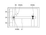
- the adhesive structure 83 includes a structure in which the adhesive 59 is provided with reference to the position of the hole in a state where the insertion portion of the substrate 81 is inserted into the hole of the object 80 .
- a portion of the substrate 81 is inserted into the through hole 58 of the object 80.
- the through-hole 58 corresponds to an embodiment of the hole included in the object according to the present technology.
- the shape of the hole that the object 80 has is not limited.
- a concave portion may be provided as the hole, and a portion of the substrate 81 may be inserted.
- the portion of the substrate 81 that is inserted into the through hole 58 corresponds to an embodiment of the insertion portion of the substrate according to the present technology.
- the insertion portion 86 is indicated by a dotted pattern.
- the convex portion 55 formed on the IMU board 26 corresponds to an embodiment of the insertion portion of the board according to the present technology.
- the adhesive 59 is provided with reference to the positions of the holes.
- the adhesive 59 is provided so as to cover at least part of the opening of the through-hole 58 .
- an adhesive 59 is provided between the object 80 and the substrate 81 so as to partially cover the opening on the right side of the through hole 58 .
- the adhesive 59 is provided so as to cover at least a portion of the opening on the side where the projection 55 is inserted.
- the adhesive 59 may be provided so as to cover all of the two openings.
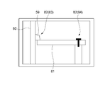
- the object 80 has a flat surface, and the substrate 81 is arranged near the surface.
- the substrate 81 is spaced apart from the object 80 so that the surface of the substrate 81 is perpendicular to the flat surface of the object 80 .
- an adhesive 59 is provided near the object 80 on the upper surface of the substrate 81 .
- the substrate 81 is adhered to the surface of the object 80 .
- the object 80 and the substrate 81 are arranged separately, and the adhesive 59 is provided between the side of the object 80 and the side of the substrate 81 . In this manner, the object 80 and the substrate 81 may be bonded by bridging the respective sides with the adhesive 59 .
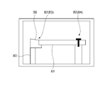
- the adhesive 59 is filled inside the through hole 58 .
- the adhesive 59 is filled in the entire space inside the through-hole 58 except for the area occupied by the insertion portion 86 . That is, the upper and lower portions of the insertion portion 86 are filled with the adhesive 59 so as to completely fill the space.
- a part of the space inside the through hole 58 may be filled with the adhesive 59 .
- a method of providing an adhesive 59 that covers at least a part of the opening of the through hole 58 shown in FIG. 9 and the like and a method of filling the inside of the through hole 58 with the adhesive 59 shown in FIG. 12 are realized simultaneously. good too. That is, a configuration may be employed in which the adhesive 59 filled inside the through hole 58 overflows the outside of the through hole 58 to cover the opening.
- the shape of the hole that the substrate 81 has is not limited. For example, recesses may be provided as holes.
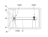
- the bonding structure a structure in which an adhesive material is provided based on the position of the hole in a state where the insertion portion of the object 80 is inserted into the hole of the substrate 81 may be adopted.
- An object 80 is shown on the left side of FIG.
- the object 80 has an insertion portion 88 at its tip portion facing upward.
- the insertion portion 88 is indicated by a dotted pattern.
- the insertion section 88 corresponds to an embodiment of the insertion section of the object according to the present technology.
- a boss configured on the object 80 functions as the insertion portion 88 .
- the specific shape and the like of the insertion portion 88 are not limited.
- the adhesive 59 is provided with reference to the positions of the holes.
- the insertion portion 88 is inserted into the through hole 87 so as to protrude upward.
- An adhesive 59 is provided to cover the upper opening of the through hole 87 .
- the adhesive 59 is provided in contact with the surface of the upper portion of the insertion portion 88 and the upper portion of the substrate 81 near the through hole 87 . Thereby, the substrate 81 and the object 80 are adhered.
- various variations of the bonding structure 83 as shown in FIGS. 9 to 13 can be adopted according to the configuration of the object 80, the substrate 81, and the like.
- effective adhesion can be realized by adopting an adhesion structure 83 as shown in FIG.
- through holes 87 may function as positioning holes for substrate 81 .
- the specific structure of the bonding structure 83 is not limited, and any structure may be adopted.
- the bonding may be over a wide area such that the entire side of the substrate 81 is bonded.
- the IMU board 26 is fixed by screwing, but the pressing structure 84 is not limited to such a structure. Variations of the pressing structure 84 will be described below.
- FIG. 14 and 15 are schematic diagrams showing an example of the pressing structure 84.
- FIG. 14 and 15 show different examples of the pressing structure 84.
- FIG. 14 and 15, the object 80 and the substrate 81 are bonded by the bonding structure 83 at a portion not shown.
- the pressing structure 84 is a structure for sandwiching and fixing the substrate 81 between the object 80 .
- the object 80 has a first fixing portion 89 projecting rightward. It also has a second fixing portion 90 protruding leftward.
- the substrate 81 is sandwiched between the first fixing portion 89 and the second fixing portion 90 . That is, the substrate 81 is sandwiched such that the first fixing portion 89 is brought into contact with the left side surface of the substrate 81 and the second fixing portion 90 is brought into contact with the right side surface of the substrate 81, pressed and fixed.
- each of the front holder 18 and the rear holder 29 is provided with a convex portion, and the IMU board 26 is sandwiched and fixed by each convex portion.
- the front holder 18 and the rear holder 29 correspond to the object 80 .
- the convex portion of the front holder 18 corresponds to the first fixing portion 89
- the convex portion of the rear holder 29 corresponds to the second fixing portion 90 .
- each specific shape is not limited.
- the method of pinching and fixing by the object 80 is not limited, and any method may be adopted.
- At least one of the first fixing portion 89 and the second fixing portion 90 may fix the substrate 81 via an elastic body.
- a plate-like elastic body 91 is sandwiched between the first fixing portion 89 and the substrate 81 . Therefore, the left side surface of the substrate 81 is in contact with the right side surface of the elastic body 91, and the right side surface is in contact with the second fixing portion 90, so that the substrate 81 is sandwiched. pressed and fixed.
- the substrate 81 is fixed via the elastic member 91 only by the first fixing portion 89 , but of course the elastic member 91 is sandwiched only between the second fixing portion 90 and the substrate 81 .
- the elastic body 91 may be sandwiched between both the first fixing portion 89 and the substrate 81 and between the second fixing portion 90 and the substrate 81 .
- any elastic member such as rubber or a spring may be used.
- the method for fixing the substrate 81 via the elastic body 91 is not limited.
- the substrate 81 may be fixed by a method other than the method in which the elastic body 91 is sandwiched between the substrate 81 and the fixing portion.
- the substrate 81 can be stably fixed by the pressing structure 84 that sandwiches and fixes the substrate 81 between the objects 80 . Specifically, since the substrate 81 is strongly pressed by the force applied from the first fixing portion 89 and the second fixing portion 90, the substrate 81 is not fixed to the fixed portion when force acts on the substrate 81 from the outside. It becomes less likely to slip off or come off from the fixing point.
- the substrate 81 is fixed via the elastic body 91, by appropriately adjusting the elasticity of the elastic body 91, it is possible to press and fix with a desired force. For example, by using the elastic body 91 having great elasticity, it is possible to stably fix the substrate 81 with a strong force.
- connection structure portion 82 [Arrangement Configuration of Connection Structure] In this embodiment, the position of each of the two or more connection structures 82 is set with reference to the position of the inertial sensor 10 on the substrate 81 . Variations in the arrangement configuration of the connection structure portion 82 will be described below.
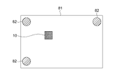
- connection structure portions 82 are formed at three locations of the substrate 81 , the upper left corner, the lower left corner, and the upper right corner. Moreover, the inertial sensor 10 is arranged so as to be surrounded by the connecting structure portions 82 at three locations.
- the inertial sensor 10 is arranged so as to be surrounded by the three connection structures 82 .
- an adhesive structure 83 is constructed.
- a pressing structure 84 is formed at a corner portion on the positive side in the X direction and the positive side in the Z direction.
- the IMU sensor 60 is arranged near the center of the IMU board 26 so as to be surrounded by three connection structures 82 .
- connection structure portions 82 are formed at four locations, namely, the upper left corner, the lower left corner, the upper right corner, and the center of the lower side of the substrate 81 .
- the inertial sensor 10 is arranged so as to be surrounded by the connection structures 82 at four locations.
- the inertial sensor 10 is arranged so as to be surrounded by, for example, two or more connection structures 82 . That is, the position of the inertial sensor 10 is set with reference to the positions of the two or more connection structures 82 . In other words, the position of each of the two or more connection structures 82 is set so as to surround the inertial sensor 10 on the basis of the position of the inertial sensor 10 .
- connection structure portion 82 may be configured at a portion other than the corner portion of the substrate 81 . Further, for example, when there are two connection structure portions 82 , the connection structure portions 82 may be arranged such that the inertial sensor 10 is positioned between the connection structure portions 82 . In addition, the position may be set by any method. Also, the combination of the bonding structure 83 and the pressing structure 84 of each connection structure 82 is not limited.
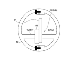
- the inertial sensor 10 is arranged at the center of gravity of each position of the two or more connecting structures 82 .
- the inertial sensor 10 is arranged at the triangular positional center of gravity formed by the three connection structures 82 .
- the inertial sensor 10 is arranged at the positional center of gravity of the quadrangle formed by the four connection structures 82 .
- the positional center of gravity is the middle point of the two connecting structure portions 82.
- FIG. Therefore, the inertial sensor 10 is arranged at the midpoint.
- the inertial sensor 10 is stably arranged on the substrate 81 .
- the connection structure 82 is formed at three locations, the upper left corner, the lower left corner, and the upper right corner, the lower right corner is attached to the object 80. It will not be fixed. Therefore, when the substrate 81 vibrates, the lower right corner is greatly affected by the vibration. For example, if the inertial sensor 10 is placed in the lower right corner, the inertial sensor 10 will vibrate and the sensing accuracy will decrease.
- the area surrounded by the connection structure 82 on the substrate 81 is less susceptible to vibration.
- the inertial sensor 10 is arranged in a location surrounded by the connection structure 82, the influence of vibration on the inertial sensor 10 can be suppressed. This makes it possible to improve the measurement accuracy of the inertial sensor 10 .
- the positional center of gravity of each connection structure portion 82 is a location that is particularly resistant to vibration.
- the inertial sensor 10 is arranged at the positional center of gravity, it is possible to greatly suppress the influence of vibration on the inertial sensor 10 . This makes it possible to improve the measurement accuracy of the inertial sensor 10 .
- connection structures 82 are configured at two locations, for example, the upper left corner and the upper right corner of the substrate 81 , and the inertial sensor 10 is arranged at the center of the substrate 81 .
- connection structure portions 82 for connecting the substrate 81 to the object 80 are formed at two or more locations of the substrate 81 .
- Each of the two or more connection structures 82 is composed of a bonding structure 83 in which an adhesive 59 is provided between the object 80 and the substrate 81 that are spaced apart from each other.
- one of the two or more connection structures 82 is configured by a pressing structure 84 that presses and fixes the substrate 81 to the object 80 , and the other is configured by an adhesive structure 83 . This makes it possible to improve the measurement accuracy of the inertial sensor 10 .
- the substrate 81 is fixed while suppressing the stress acting on the substrate 81 due to the configuration in which the entire connection structure portion 82 is the bonding structure 83 . Moreover, since the substrate 81 is fixed at two or more locations, the influence of vibration is suppressed. This makes it possible to improve the measurement accuracy of the inertial sensor 10 .
- expressions using "more than” such as “greater than A” and “less than A” encompass both the concept including the case of being equivalent to A and the concept not including the case of being equivalent to A. is an expression contained in For example, “greater than A” is not limited to not including equal to A, but also includes “greater than or equal to A.” Also, “less than A” is not limited to “less than A”, but also includes “less than A”. When implementing the present technology, specific settings and the like may be appropriately adopted from concepts included in “greater than A” and “less than A” so that the effects described above are exhibited.
- a holding structure for installing a substrate on which an inertial sensor is arranged on an object comprising two or more connection structures configured at two or more locations on the substrate for connecting the substrate to the object;
- Each of the two or more connection structure parts is configured by an adhesion structure in which an adhesion material is provided between the object and the substrate that are arranged to be spaced apart from each other.
- one of the two or more connecting structure portions is configured by a pressing structure that presses and fixes the substrate to the object, and the other is configured by the bonding structure.
- the holding structure according to (1) The holding structure, wherein the pressing structure includes a structure for fixing the substrate to the object via a fastening member.
- the adhesion structure includes a structure in which the adhesion material is provided with reference to the position of the hole in a state in which the insertion portion of the substrate is inserted into the hole of the object.
- the holding structure according to (6), The hole is a through hole Retaining structure.
- the holding structure according to any one of (1) to (9), The holding structure includes a structure in which the bonding structure includes a structure in which the bonding material is provided with reference to the position of the hole in a state in which the insertion portion of the object is inserted into the hole of the substrate.
- the holding structure according to any one of (1) to (14), The holding structure, wherein the position of the inertial sensor is set based on the position of each of the two or more connection structures.
- the holding structure according to (15), The inertial sensor is arranged at the center of gravity of each position of the two or more connecting structures.
- a holding method for installing a substrate on which an inertial sensor is arranged on an object A holding method in which each of two or more locations of the substrate is connected to the object by an adhesive structure in which an adhesive material is provided between the object and the substrate that are spaced apart from each other.
- a holding method for installing a substrate on which an inertial sensor is arranged on an object connecting one of two or more locations of the substrate to the object by a pressing structure that presses and fixes the substrate to the object;
- a holding method in which the other of the two or more locations is connected to the object by an adhesive structure in which an adhesive material is provided between the object and the substrate that are arranged so as to be spaced apart from each other.
Landscapes
- Engineering & Computer Science (AREA)
- Physics & Mathematics (AREA)
- General Physics & Mathematics (AREA)
- Microelectronics & Electronic Packaging (AREA)
- Radar, Positioning & Navigation (AREA)
- Remote Sensing (AREA)
- Multimedia (AREA)
- Signal Processing (AREA)
- Studio Devices (AREA)
Priority Applications (2)
| Application Number | Priority Date | Filing Date | Title |
|---|---|---|---|
| JP2023520788A JPWO2022239347A1 (enExample) | 2021-05-12 | 2022-02-16 | |
| US18/556,690 US20240373576A1 (en) | 2021-05-12 | 2022-02-16 | Holding structure and holding method |
Applications Claiming Priority (2)
| Application Number | Priority Date | Filing Date | Title |
|---|---|---|---|
| JP2021080971 | 2021-05-12 | ||
| JP2021-080971 | 2021-05-12 |
Publications (1)
| Publication Number | Publication Date |
|---|---|
| WO2022239347A1 true WO2022239347A1 (ja) | 2022-11-17 |
Family
ID=84029017
Family Applications (1)
| Application Number | Title | Priority Date | Filing Date |
|---|---|---|---|
| PCT/JP2022/006153 Ceased WO2022239347A1 (ja) | 2021-05-12 | 2022-02-16 | 保持構造及び保持方法 |
Country Status (3)
| Country | Link |
|---|---|
| US (1) | US20240373576A1 (enExample) |
| JP (1) | JPWO2022239347A1 (enExample) |
| WO (1) | WO2022239347A1 (enExample) |
Citations (6)
| Publication number | Priority date | Publication date | Assignee | Title |
|---|---|---|---|---|
| JP2008224428A (ja) * | 2007-03-13 | 2008-09-25 | Denso Corp | センサ装置 |
| JP2010230329A (ja) * | 2009-03-25 | 2010-10-14 | Panasonic Electric Works Co Ltd | 基板固定構造および物理量センサ |
| JP2012084777A (ja) * | 2010-10-14 | 2012-04-26 | Toyota Motor Corp | センサユニットの組付け方法、製造方法及び冶具 |
| JP2013019745A (ja) * | 2011-07-11 | 2013-01-31 | Seiko Epson Corp | センサーデバイスおよび電子機器 |
| US20130308046A1 (en) * | 2012-05-15 | 2013-11-21 | Samsung Electronics Co., Ltd. | Imaging apparatus and method of manufacturing the same |
| US20190002125A1 (en) * | 2016-01-26 | 2019-01-03 | SZ DJI Technology Co., Ltd. | Stabilizing platform and camera |
Family Cites Families (5)
| Publication number | Priority date | Publication date | Assignee | Title |
|---|---|---|---|---|
| JP5133550B2 (ja) * | 2006-10-18 | 2013-01-30 | ペンタックスリコーイメージング株式会社 | 手振補正機能付カメラにおけるジャイロセンサ取付構造 |
| EP3171131A4 (en) * | 2014-07-16 | 2018-03-07 | Seiko Epson Corporation | Sensor unit, electronic apparatus, and mobile body |
| JP6597069B2 (ja) * | 2015-09-02 | 2019-10-30 | セイコーエプソン株式会社 | センサーユニット、電子機器、および移動体 |
| JP2020067330A (ja) * | 2018-10-23 | 2020-04-30 | セイコーエプソン株式会社 | 慣性センサーユニットの取り付け方法、および慣性センサーユニット |
| CN112880667B (zh) * | 2019-11-29 | 2023-12-08 | 精工爱普生株式会社 | 传感器单元、电子设备以及移动体 |
-
2022
- 2022-02-16 WO PCT/JP2022/006153 patent/WO2022239347A1/ja not_active Ceased
- 2022-02-16 US US18/556,690 patent/US20240373576A1/en active Pending
- 2022-02-16 JP JP2023520788A patent/JPWO2022239347A1/ja active Pending
Patent Citations (6)
| Publication number | Priority date | Publication date | Assignee | Title |
|---|---|---|---|---|
| JP2008224428A (ja) * | 2007-03-13 | 2008-09-25 | Denso Corp | センサ装置 |
| JP2010230329A (ja) * | 2009-03-25 | 2010-10-14 | Panasonic Electric Works Co Ltd | 基板固定構造および物理量センサ |
| JP2012084777A (ja) * | 2010-10-14 | 2012-04-26 | Toyota Motor Corp | センサユニットの組付け方法、製造方法及び冶具 |
| JP2013019745A (ja) * | 2011-07-11 | 2013-01-31 | Seiko Epson Corp | センサーデバイスおよび電子機器 |
| US20130308046A1 (en) * | 2012-05-15 | 2013-11-21 | Samsung Electronics Co., Ltd. | Imaging apparatus and method of manufacturing the same |
| US20190002125A1 (en) * | 2016-01-26 | 2019-01-03 | SZ DJI Technology Co., Ltd. | Stabilizing platform and camera |
Also Published As
| Publication number | Publication date |
|---|---|
| JPWO2022239347A1 (enExample) | 2022-11-17 |
| US20240373576A1 (en) | 2024-11-07 |
Similar Documents
| Publication | Publication Date | Title |
|---|---|---|
| JP6921601B2 (ja) | 振れ補正機能付き光学ユニット | |
| CN106353950B (zh) | 带有抖动校正功能的光学单元以及其制造方法 | |
| TW201908849A (zh) | 帶抖動修正功能的光學單元 | |
| CN102809373B (zh) | 模块以及电子设备 | |
| TW201821782A (zh) | 附有震動校正功能之光學單元 | |
| JP6483980B2 (ja) | 振れ補正機能付き光学ユニット | |
| CN111128059A (zh) | 显示设备 | |
| JP6451112B2 (ja) | センサーユニット、電子機器、および移動体 | |
| JP6800707B2 (ja) | 振れ補正機能付き光学ユニット | |
| JP2018180506A (ja) | 光学ユニットおよび3軸振れ補正機能付き光学ユニット | |
| JP2015161640A (ja) | 電子デバイス、電子機器、および移動体 | |
| KR20230118532A (ko) | 플렉서블 디스플레이 모듈 및 이를 포함하는 전자장치 | |
| JP2015141329A (ja) | レンズ駆動装置 | |
| JP6985876B2 (ja) | 撮像装置 | |
| JP6811589B2 (ja) | 振れ補正機能付き光学ユニット | |
| WO2022239347A1 (ja) | 保持構造及び保持方法 | |
| JP2007057288A (ja) | 圧電ジャイロセンサモジュール及び電子機器 | |
| JP2006133004A (ja) | 角速度センサ | |
| WO2022239346A1 (ja) | 撮像装置 | |
| JP6607234B2 (ja) | レンズ駆動装置 | |
| JP7123784B2 (ja) | タッチパネル付き表示装置 | |
| KR102562034B1 (ko) | 플렉서블 디스플레이 모듈 및 이를 포함하는 전자장치 | |
| JP6500423B2 (ja) | センサーユニット、電子機器、および移動体 | |
| WO2012114768A1 (ja) | 電子機器 | |
| JP7192437B2 (ja) | 慣性センサー、電子機器および移動体 |
Legal Events
| Date | Code | Title | Description |
|---|---|---|---|
| 121 | Ep: the epo has been informed by wipo that ep was designated in this application |
Ref document number: 22807054 Country of ref document: EP Kind code of ref document: A1 |
|
| WWE | Wipo information: entry into national phase |
Ref document number: 2023520788 Country of ref document: JP |
|
| NENP | Non-entry into the national phase |
Ref country code: DE |
|
| 122 | Ep: pct application non-entry in european phase |
Ref document number: 22807054 Country of ref document: EP Kind code of ref document: A1 |