WO2022239221A1 - 熱伝導部材、熱伝導部材の製造方法およびバッテリー - Google Patents
熱伝導部材、熱伝導部材の製造方法およびバッテリー Download PDFInfo
- Publication number
- WO2022239221A1 WO2022239221A1 PCT/JP2021/018347 JP2021018347W WO2022239221A1 WO 2022239221 A1 WO2022239221 A1 WO 2022239221A1 JP 2021018347 W JP2021018347 W JP 2021018347W WO 2022239221 A1 WO2022239221 A1 WO 2022239221A1
- Authority
- WO
- WIPO (PCT)
- Prior art keywords
- elastic sheet
- heat
- conductive film
- thermally conductive
- thickness direction
- Prior art date
- Legal status (The legal status is an assumption and is not a legal conclusion. Google has not performed a legal analysis and makes no representation as to the accuracy of the status listed.)
- Ceased
Links
Images





Classifications
-
- H—ELECTRICITY
- H01—ELECTRIC ELEMENTS
- H01M—PROCESSES OR MEANS, e.g. BATTERIES, FOR THE DIRECT CONVERSION OF CHEMICAL ENERGY INTO ELECTRICAL ENERGY
- H01M10/00—Secondary cells; Manufacture thereof
- H01M10/60—Heating or cooling; Temperature control
- H01M10/61—Types of temperature control
- H01M10/613—Cooling or keeping cold
-
- H—ELECTRICITY
- H01—ELECTRIC ELEMENTS
- H01M—PROCESSES OR MEANS, e.g. BATTERIES, FOR THE DIRECT CONVERSION OF CHEMICAL ENERGY INTO ELECTRICAL ENERGY
- H01M10/00—Secondary cells; Manufacture thereof
- H01M10/60—Heating or cooling; Temperature control
- H01M10/65—Means for temperature control structurally associated with the cells
- H01M10/653—Means for temperature control structurally associated with the cells characterised by electrically insulating or thermally conductive materials
-
- H—ELECTRICITY
- H01—ELECTRIC ELEMENTS
- H01M—PROCESSES OR MEANS, e.g. BATTERIES, FOR THE DIRECT CONVERSION OF CHEMICAL ENERGY INTO ELECTRICAL ENERGY
- H01M10/00—Secondary cells; Manufacture thereof
- H01M10/60—Heating or cooling; Temperature control
- H01M10/65—Means for temperature control structurally associated with the cells
- H01M10/655—Solid structures for heat exchange or heat conduction
- H01M10/6554—Rods or plates
-
- H—ELECTRICITY
- H05—ELECTRIC TECHNIQUES NOT OTHERWISE PROVIDED FOR
- H05K—PRINTED CIRCUITS; CASINGS OR CONSTRUCTIONAL DETAILS OF ELECTRIC APPARATUS; MANUFACTURE OF ASSEMBLAGES OF ELECTRICAL COMPONENTS
- H05K7/00—Constructional details common to different types of electric apparatus
- H05K7/20—Modifications to facilitate cooling, ventilating, or heating
-
- Y—GENERAL TAGGING OF NEW TECHNOLOGICAL DEVELOPMENTS; GENERAL TAGGING OF CROSS-SECTIONAL TECHNOLOGIES SPANNING OVER SEVERAL SECTIONS OF THE IPC; TECHNICAL SUBJECTS COVERED BY FORMER USPC CROSS-REFERENCE ART COLLECTIONS [XRACs] AND DIGESTS
- Y02—TECHNOLOGIES OR APPLICATIONS FOR MITIGATION OR ADAPTATION AGAINST CLIMATE CHANGE
- Y02E—REDUCTION OF GREENHOUSE GAS [GHG] EMISSIONS, RELATED TO ENERGY GENERATION, TRANSMISSION OR DISTRIBUTION
- Y02E60/00—Enabling technologies; Technologies with a potential or indirect contribution to GHG emissions mitigation
- Y02E60/10—Energy storage using batteries
Definitions
- the present invention relates to a heat-conducting member, a manufacturing method thereof, and a battery including the heat-conducting member.
- the circuit board itself is made of a material with excellent heat dissipation properties, a heat sink is attached, or a cooling fan is driven. It is done.
- the method of forming the circuit board itself from a material having excellent heat dissipation properties such as diamond, aluminum nitride (AlN), or cubic boron nitride (cBN)
- the arrangement of the cooling fan causes problems such as the need for maintenance to prevent failures of the fan, which is a rotating device, and the difficulty in securing the installation space.
- heat radiation fins have a large number of pillar-shaped or plate-shaped protruding parts made of a metal with high thermal conductivity (e.g., aluminum). Because it is a flexible member, it is widely used as a heat dissipation component.
- a metal with high thermal conductivity e.g., aluminum
- a heat conduction member for promoting heat dissipation from the heat source described above for example, a member is known in which thin sheets with excellent heat conductivity are alternately exposed in the front and back directions of a resin sheet (Patent See References 1 and 2).
- the conventionally known heat conduction members described above have the following problems.
- a heat conducting member is interposed between the heat source and the cooling member, close contact between the heat conducting member and the heat source or the cooling member is important in order to improve the performance of heat conduction from the heat source to the cooling member. For this reason, it is preferable to compress the heat-conducting member by applying pressure in the thickness direction of the heat-conducting member.
- the heat-conducting member is sandwiched between the heat source and the cooling member, the heat-conducting film exposed on the front or back surface of the heat-conducting member may be damaged. As a result, heat transfer from the heat source to the cooling member via the heat conducting member may be reduced.
- the present invention has been made in view of the above problems, and aims to increase the heat conduction of a heat conducting member interposed between a heat source and a cooling member.
- a heat conduction member is a heat conduction member that can be interposed between a heat source and a cooling member to transfer heat from the heat source to the cooling member.
- a film with The elastic sheet has a tapered portion or a curved portion at the edge in contact with the heat conductive film, The heat conductive film covers the tapered member or the curved portion of the elastic sheet.
- the area covered by the heat-conducting film protrudes beyond the thickness of the heat-conducting film.
- the elastic sheet has a region covered by the heat-conducting film on one side in the thickness direction of the elastic sheet, which is larger than a region not covered by the heat-conducting film. You may have the protrusion part which protrudes also.
- the elastic sheet has an area covered by the heat-conducting film on both sides in the thickness direction of the elastic sheet, which is larger than the area not covered by the heat-conducting film.
- the elastic sheet on at least one side in the thickness direction, covers part or all of the region excluding the region covered by the heat-conducting film. , an adhesive layer capable of adhering to the heat source or the cooling member. (6) In the heat-conducting member according to another embodiment, preferably, the height of the adhesive layer on the elastic sheet may be equal to or less than that of the heat-conducting film.
- the elastic sheet includes members having different hardnesses with the thermally conductive film sandwiched therebetween, and one side of the elastic sheet in the thickness direction is more It may be a surface of a member having high hardness covered with the heat conductive film.
- the elastic sheet is a foam sheet and has holes mainly extending in the thickness direction of the elastic sheet.
- a method for manufacturing a thermally conductive member is a method for manufacturing any of the thermally conductive members described above, a through-hole forming step of forming a plurality of through-holes penetrating the elastic sheet from the front side surface to the back side surface in the thickness direction at predetermined intervals; a heat conductive film placing step of placing the heat conductive film on the front surface of the elastic sheet so as to cover the through holes; an elastic sheet piece inserting step of inserting an elastic sheet piece into the through hole from above the heat conductive film to expose the heat conductive film from the back surface; including.
- the through-hole forming step includes forming the through-hole and forming the elastic sheet piece connected to a part of the opening of the through-hole.
- a step of rotating and retreating from the through hole, The step of inserting the elastic sheet piece may be a step of rotating the elastic sheet piece toward the through hole and inserting it into the through hole.
- the heat source is one or two or more battery cells
- the cooling member is a housing containing the battery cells
- any one of the above heat-conducting members is the It is interposed between the battery cell and the housing.
- the heat conduction of the heat conducting member interposed between the heat source and the cooling member can be enhanced.
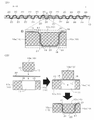
- FIG. 1 shows a plan view, a right side view, and a front view (1A) of a heat conduction member according to a first embodiment, and a perspective view (1B) of the heat conduction member.
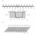
- 2 is a cross-sectional view of the heat-conducting member of FIG. 1 taken along line AA in the plan view, an enlarged view (2A) of part B thereof, and a part of the manufacturing process of the heat-conducting member.
- 2B shows an enlarged cross-sectional view of the situation (2B).
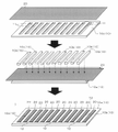
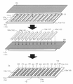
- FIG. 3 shows a perspective view for explaining an example of a method for manufacturing the heat-conducting member of FIG.
- FIG. 4 shows a perspective view for explaining a modification of the manufacturing method of FIG. FIG.
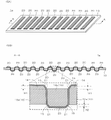
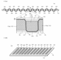
- FIG. 5 shows a perspective view (5A) of a heat conduction member according to the second embodiment, a cross-sectional view taken along line AA in the perspective view of the heat conduction member, and an enlarged view (5B) of a portion B thereof.
- FIG. 6 shows an enlarged cross-sectional view of a part of the manufacturing process of the heat-conducting member of FIG.
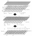
- FIG. 7 shows a perspective view for explaining an example of a method of manufacturing the heat conducting member of FIG.
- FIG. 8 shows a perspective view for explaining a modification of the manufacturing method of FIG. FIG.
- FIG. 9 is a cross-sectional view of a heat-conducting member according to a modification in which an adhesive layer is provided in a region other than the heat-conducting film of the heat-conducting member according to the first embodiment of FIG.
- An enlarged view (9A) of part B and a perspective view (9B) of a thermally conductive member provided with the adhesive layer are shown.
- FIG. 10 is a cross-sectional view of a heat-conducting member according to a modification in which an adhesive layer is provided in a region other than the heat-conducting film of the heat-conducting member according to the second embodiment of FIG.
- An enlarged view (10A) of part B and a perspective view (10B) of a thermally conductive member provided with the adhesive layer are shown.
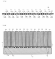
- FIG. 11 is a cross-sectional view (11A) of the heat-conducting member according to the third embodiment taken in the thickness direction and parallel to the length direction, and a battery cell using the heat-conducting member as a heat source.
- 11B is a cross-sectional view (11B) of a state in which it is arranged so as to be sandwiched between and a housing as a cooling member.
- FIG. 12 is a cross-sectional view of the heat-conducting member according to the fourth embodiment taken along its thickness direction and parallel to its length direction, and an enlarged view (12A) of a part B thereof;
- Figure 12B shows an electron micrograph (12B) of a cross-section of the elastic sheet of the conductive member;
- FIG. 13 shows a longitudinal cross-sectional view of a battery with heat-conducting members.
- FIG. 14 shows a cross-sectional view when the battery cell is placed horizontally so that the side surface of the battery cell is in contact with the heat-conducting member, a partially enlarged view thereof, and a partial cross-sectional view when the battery cell expands during charging and discharging. show.
- FIG. 1 shows a plan view, a right side view, and a front view (1A) of a heat conduction member according to a first embodiment, and a perspective view (1B) of the heat conduction member.
- the thickness direction, width direction and length direction refer to the direction of the shortest side of the rectangular parallelepiped, the direction of the next longest side after the thickness direction, and the direction of the longest side, respectively.
- the heat-conducting member 1 is a member that can be interposed between a heat source and a cooling member to transfer heat from the heat source to the cooling member.
- the heat-conducting member 1 includes an elastic sheet 10 and a heat-conducting film 20 .
- the elastic sheet 10 is a sheet elastically deformable at least in the thickness direction.
- the elastic sheet 10 may be elastically deformable in the width direction and the length direction as long as it is elastically deformable in the thickness direction.
- the heat-conducting film 20 is alternately exposed on the front side surface and the back side surface in the thickness direction of the elastic sheet 10 and is perpendicular to the thickness direction of the elastic sheet 10 in a predetermined direction (here, the elastic sheet 10 (longitudinal direction)).
- the elastic sheet 10 preferably holds the heat conductive film 20 by piercing the heat conductive film 20 in the thickness direction and arranging the unevenness repeatedly. That is, the elastic sheet 10 holds the heat conductive film 20 so that the heat conductive film 20 is exposed at a predetermined interval on the surface facing the heat source and the surface facing the cooling member.
- the elastic sheet 10 is preferably a thin sheet whose length in the thickness direction is extremely small compared to the width direction and the length direction.
- the thermally conductive film 20 according to this embodiment is a film that has higher thermal conductivity and lower stretchability than the elastic sheet 10 .
- the heat-conducting film 20 is exposed in the longitudinal direction of the elastic sheet 10, preferably at a constant pitch, on the front surface.
- the heat-conducting film 20 is also exposed on the back side of the elastic sheet 10 in the longitudinal direction, preferably at a constant pitch.
- the pitch is not constant and may be different.
- the elastic sheet 10 An important function of the elastic sheet 10 is to give the thermal conduction member 1 ease of deformation and recovery force.
- the resilience is due to the elastic deformability of the elastic sheet 10 .
- Ease of deformation is due to flexibility of the elastic sheet 10 .
- the thickness of the elastic sheet 10 is not limited, it preferably has a thickness of 0.2 to 20 mm, more preferably 0.5 to 10 mm. Also, the thickness of the elastic sheet 10 is preferably greater than the thickness of the thermal conductive film 20 .
- the elastic sheet 10 is preferably made of thermosetting elastomer such as silicone rubber, urethane rubber, isoprene rubber, ethylene propylene rubber, natural rubber, ethylene propylene diene rubber, nitrile rubber (NBR) or styrene butadiene rubber (SBR); , ester-based, styrene-based, olefin-based, butadiene-based, fluorine-based thermoplastic elastomers, or composites thereof. It is preferable that the elastic sheet 10 is made of a material having high heat resistance so as to maintain its shape without being melted or decomposed by the heat transmitted through the heat conductive film 20 .
- thermosetting elastomer such as silicone rubber, urethane rubber, isoprene rubber, ethylene propylene rubber, natural rubber, ethylene propylene diene rubber, nitrile rubber (NBR) or styrene butadiene rubber (SBR); , ester-based,
- the elastic sheet 10 is more preferably made of urethane-based elastomer impregnated with silicone or silicone rubber.
- the elastic sheet 10 is a silicone rubber sheet.
- the elastic sheet 10 may be formed by dispersing fillers such as Al 2 O 3 , AlN, cBN, hBN, and diamond particles in rubber in order to increase its thermal conductivity.
- the elastic sheet 10 is more preferably a highly cushioned sponge containing air bubbles therein.
- elastic sheet 10 is a foam sheet.
- the "elastic sheet” means a flexible and elastically deformable member, and in this sense can be read as "cushion member", "cushion sheet” or "rubber-like elastic body”.
- the material of the thermally conductive film 20 is not particularly limited, but is preferably a flexible member containing at least one of metal, carbon, or ceramics.
- Thermal conductive film 20 is more preferably a carbon film or a carbon-containing resin film.
- the thermal conductive film 20 is preferably a film composed of 90% by mass or more of carbon.
- a graphite film obtained by baking a resin can be used as the heat conductive film 20 .
- the thermal conductive film 20 may be a film containing carbon and resin.
- the resin may be a synthetic fiber, and in that case, an aramid fiber can be preferably used as the resin.
- the thermal conductive film 20 can be a thin film obtained by curing a material in which graphite fibers or carbon particles are blended and dispersed in a resin.
- the thermally conductive film 20 may be carbon fiber woven into a mesh, or may be blended or blended.
- Various fillers such as graphite fibers, carbon particles, and carbon fibers are all included in the concept of carbon filler.
- the thermally conductive film 20 may be referred to as a "thermally conductive sheet".
- the resin may exceed 50% by mass or may be 50% by mass or less of the total mass of the thermally conductive film 20. . That is, it does not matter whether or not the heat conductive film 20 is mainly made of a resin as long as it does not interfere with heat conduction.
- a thermoplastic resin can be preferably used.
- the thermoplastic resin a resin having a high melting point that does not melt when conducting heat from a heat source is preferable.
- Group polyamides (aramid fibers) and the like can be preferably used.
- the resin is dispersed, for example, in the form of particles or fibers in the gaps between the carbon fillers before the heat conductive film 20 is molded.
- the thermally conductive film 20 may have Al 2 O 3 , AlN, or diamond dispersed therein as a filler for further enhancing thermal conductivity, in addition to carbon filler and resin. Further, instead of resin, rubber that is more flexible than resin may be used. Thermally conductive film 20 can also be a film comprising metals and/or ceramics instead of or in combination with carbon as described above. As the metal, a metal having relatively high thermal conductivity such as aluminum, copper, or an alloy containing at least one of them can be selected. As the ceramics, those having relatively high thermal conductivity such as Al 2 O 3 , AlN, cBN and hBN can be selected.
- the orientation direction of the filler is controlled by methods such as flow orientation, stretch orientation, and magnetic field orientation during the molding of the heat conductive film to improve thermal conductivity in a specific direction. You may use the method of raising more.
- the heat conductivity of the heat conductive film 20 is preferably 10 W/mK or more.
- the thermally conductive film 20 is preferably a graphite film, which is a material with good thermal and electrical conductivity.
- the heat-conducting film 20 is preferably a film with excellent curvature (or flexibility), and although there are no restrictions on its thickness, it is preferably 0.02 to 3 mm, more preferably 0.03 to 0.5 mm.
- the regions of the front and back surfaces of the elastic sheet 10 covered by the thermally conductive film 20 protrude from the front and back surfaces of the elastic sheet 10 by at least the thickness of the thermally conductive film 20 . .
- a region of the heat conductive film 20 on either one of the front side surface and the back side surface of the elastic sheet 10 is projected from the one side of the elastic sheet 10 by at least the thickness of the heat conductive film 20.
- FIG. 2 is a cross-sectional view of the heat-conducting member of FIG. 1 taken along line AA in the plan view, an enlarged view (2A) of part B thereof, and a part of the manufacturing process of the heat-conducting member.
- 2B shows an enlarged cross-sectional view of the situation (2B).
- the elastic sheet 10 preferably has a tapered portion 15 at the edge in contact with the heat conductive film.
- the elastic sheet 10 may have a curved portion instead of the tapered portion.
- the tapered portion refers to a portion formed by dividing a corner of a substantially right-angled edge into a plane to form an inclined surface.
- a curved portion refers to a portion in which the corners of a substantially right-angled edge are arcuate, that is, curved.
- the heat conductive film 20 covers the tapered member (or curved portion) 15 of the elastic sheet 10 .
- the thermally conductive film 20 comprises a tapered portion 21 at the location of the tapered portion 15 .
- the thermal conductive film 20 is provided with a curved portion at the curved portion.
- the elastic sheet 10 has the tapered portion 15 or the curved portion at the edge in contact with the heat conducting film 20, and the heat conducting film 20 covers the tapered member 15 or the curved portion of the elastic sheet 10. Then, even if the heat conductive member 1 is sandwiched between the heat source and the cooling member in the thickness direction and compressed, the risk of the heat conductive film 20 being damaged by the edge of the elastic sheet 10 can be reduced.
- FIG. 2 (2B) showing an enlarged view area of a portion B of the heat conducting member 1
- a manufacturing method for exposing the heat conducting films 20 alternately on both sides in the thickness direction of the elastic sheet 10 will be described. do.
- elongated through holes 11 long in the width direction of the elastic sheet 10 are formed at regular intervals in the length direction of the elastic sheet 10 .
- the elastic sheet 10 has a total of eleven elongated through-holes 11 along its length.
- FIG. 2(2B) shows the vicinity of one elongated through-hole 11 and partially shows the manufacturing process.
- a tapered portion 15 is formed by cutting the edge of the opening on the front side of the elongated through hole 11 .
- the tapered portion 15 may be the entire periphery of the opening, but here, only the longitudinal edge of the elastic sheet 10 is the tapered portion 15 .
- the elastic sheet 10a formed with the elongated through-holes 11 having the tapered portions 15 is formed.
- the tapered portion 15 may also be formed on the edge of the opening on the back side of the elongated through-hole 11 .
- a curved portion may be provided instead of the tapered portion 15 .
- the thermally conductive film 20 is placed on the front surface of the elastic sheet 10a.
- the thermal conductive film 20 preferably covers the elastic sheet 10a so as to cover all the eleven elongated through-holes 11 .
- the elastic sheet piece 10b is inserted into the elongated through-hole 11 with the heat conductive film 20 interposed therebetween.
- the elastic sheet piece 10b has a tapered portion 15 at the edge of the surface in the insertion direction.
- the thermal conductive film 20 covers the tapered members 15 of the elastic sheet 10 and has tapered portions 21 at the tapered portions 15 . If the elastic sheet 10a and the elastic sheet piece 10b and/or the thermally conductive film 20 are provided with an adhesive layer, the thermally conductive member 1 becomes a member in which the elastic sheet 10 and the thermally conductive film 20 are fixed.
- the elastic sheet piece 10b is preferably a portion cut from the elastic sheet 10 when the elongated through holes 11 are formed.
- FIG. 3 shows a perspective view for explaining an example of a method of manufacturing the heat conducting member of FIG.
- the manufacturing process has been described only for a part of the area B, but in FIG. 3, the manufacturing process for the entire area of the heat conducting member will be described.
- the method for manufacturing the heat conducting member 1 includes the following steps (1), (2) and (3).
- (1) Through Hole Forming Step This step is a step of forming a plurality of elongated through holes 11 penetrating through the elastic sheet 10 from the front side surface to the back side surface in the thickness direction at predetermined intervals. Also, in this step, a tapered portion 15 or a curved portion is formed at the edge of the opening of the elongated through-hole 11 . A tapered portion 15 or a curved portion is also formed on the edge of the elastic sheet piece 10b.
- (2) Thermal Conductive Film Arranging Step This step is a step of arranging the thermal conductive film 20 on the front side surface of the elastic sheet 10 so as to preferably cover all the elongated through holes 11 .
- the heat conductive film 20 may be arranged so as to partially cover the plurality of elongated through holes 11 . In that case, multiple thermal conductive films 20 may be used to cover all the elongated through holes 11 . This point is the same in the same process in subsequent embodiments or modified examples.
- Step of inserting elastic sheet piece This step is a step of inserting the elastic sheet piece 10b into the elongated through-hole 11 from above the thermal conductive film 20 to expose the thermal conductive film 20 from the back surface.
- a part of the opening of the elongated through-hole 11 (here, one short side 13 of the opening) is connected to the elastic sheet piece 10b, and the elastic sheet piece 10b is rotated.
- the elastic sheet piece 10b can be attached to and detached from the elongated through hole 11 by rotating about the short side 13 functioning as a driving shaft. That is, when the elongated through-holes 11 are formed in the elastic sheet 10, the elastic sheet piece 10b is not completely separated from the elongated through-holes 11, but is cut so as to leave only the short sides 13 thereof.
- the above-described through-hole forming step is a step of forming the elongated through-hole 11 and rotating the elastic sheet piece 10 b connected to a part (short side 13 ) of the opening of the elongated through-hole 11 to retreat from the elongated through-hole 11 .
- the heat conductive film placement step described above the heat conductive film 20 is placed on the front surface of the elastic sheet 10 with the elastic sheet piece 10b rotated outwardly of the elastic sheet 10a so as to cover the elongated through holes 11.
- the elastic sheet piece inserting step described above can be a step of rotating the elastic sheet piece 10b toward the elongated through hole 11 and inserting it into the elongated through hole 11 (see arrow C).
- the short side 12 on the tip side of the elastic sheet piece 10b is in the form of a notch, and the short side 13 on the opposite side is in a state of being connected to the elastic sheet 10a. not cut.
- a step of forming the tapered portion 15 or the curved portion on the edge of the opening of the elongated through-hole 11 and the elastic sheet piece 10b may be separately provided after the through-hole forming step.
- FIG. 4 shows a perspective view for explaining a modification of the manufacturing method of FIG.
- the manufacturing process has been described only for a part of the area B, but in FIG. 4, the manufacturing process for the entire area of the heat conducting member will be described.
- the manufacturing method according to this modification differs from the manufacturing method of FIG. 3 in that the elastic sheet piece 10b is completely separated from the elongated through hole 11. Therefore, the manufacturing method according to the modification is as follows. First, the elongated through holes 11 are formed in the elastic sheet 10 . At this time, the elastic sheet piece 10b is completely separated from the elongated through hole 11. As shown in FIG. A tapered portion 15 or a curved portion is formed at the edge of the opening of the elongated through hole 11 . Furthermore, a tapered portion 15 or a curved portion is also formed on the edge of the elastic sheet piece 10b.
- a thermally conductive film 20 is placed on the front surface of the elastic sheet 10a in which the elongated through holes 11 are formed, preferably so as to cover all the elongated through holes 11. As shown in FIG. Finally, the elastic sheet piece 10 b is inserted from above the heat conductive film 20 toward the elongated through holes 11 .
- a step of forming the tapered portion 15 or the curved portion on the edge of the opening of the elongated through-hole 11 and the elastic sheet piece 10b may be separately provided after the through-hole forming step.
- FIG. 5 shows a perspective view (5A) of the heat conduction member according to the second embodiment, a sectional view taken along line AA in the perspective view of the heat conduction member, and an enlarged view (5B) of part B thereof.
- the area covered by the thermally conductive film 20 is made thicker than the other areas by the thickness of the thermally conductive film 20 or more. is made to protrude.
- the elastic sheet 10 makes the area covered by the heat conducting film 20 protrude from the area not covered by the heat conducting film 20 on both sides in the thickness direction. More specifically, the elastic sheet 10 according to this embodiment has 12 projections 14 that are long in the width direction of the elastic sheet 10 at predetermined intervals in the length direction. Note that the number of protrusions 14 is not limited to 12 as long as the number is two or more.
- the heat-conducting film 20 covers the surfaces of the protrusions 14 while passing through the elastic sheet 10 in the thickness direction.
- the area covered by the thermally conductive film 20 in the thermally conductive member 1a consists of the projecting portion 14 (height from the front surface of the elastic sheet 10: H1, height from the rear surface: H2) and the thickness of the thermally conductive film 20. It protrudes from the surface of the elastic sheet 10 by the total height.
- the elastic sheet 10 may be provided with a projecting portion 14 in the area of the thermal conductive film 20 on either one of the front side surface and the back side surface.
- the elastic sheet 10 preferably has a tapered portion 15 at the edge in contact with the heat-conducting film, like the heat-conducting member 1 according to the first embodiment.
- the elastic sheet 10 may have a curved portion instead of the tapered portion 15 .
- the heat conductive film 20 covers the tapered member 15 (or curved portion) of the elastic sheet 10 .
- the thermally conductive film 20 has a tapered portion 21 at the location of the tapered portion 15 . Even when the elastic sheet 10 is provided with a curved portion, the thermal conductive film 20 is provided with a curved portion at the curved portion.
- the elastic sheet 10 has the tapered portion 15 or the curved portion at the edge in contact with the thermal conductive film 20, and the thermal conductive film 20 covers the tapered member 15 or the curved portion of the elastic sheet 10.
- the thermally conductive member 1a the area where the thermally conductive film 20 exists protrudes by the sum of the thickness of the projecting portion 14 and the thermally conductive film 20, and is higher than the sheet surface. Therefore, even if the surface of the heat source (or cooling member) in contact with the surface of the heat conducting member 1a in the thickness direction has some unevenness, the heat conducting film 20 can be reliably brought into contact with the heat source or the cooling member.
- FIG. 6 shows an enlarged cross-sectional view of a part of the manufacturing process of the heat-conducting member of FIG.
- FIG. 6 illustrates the vicinity of one elongated through-hole 11 and partially shows the manufacturing process.
- a tapered portion 15 is formed by cutting the edge of the opening on the front side of the elongated through hole 11 .
- the tapered portion 15 may be the entire periphery of the opening, but here, only the longitudinal edge of the elastic sheet 10 is the tapered portion 15 .
- the elastic sheet 10a formed with the elongated through-holes 11 having the tapered portions 15 is formed.
- the tapered portion 15 may also be formed on the edge of the opening on the back side of the elongated through-hole 11 .
- a curved portion may be provided instead of the tapered portion 15 .
- the thermally conductive film 20 is placed on the front surface of the elastic sheet 10a.
- the thermal conductive film 20 preferably covers the elastic sheet 10a so as to cover all the eleven elongated through-holes 11 .
- the elastic sheet piece 10b is inserted into the elongated through-hole 11 with the heat conductive film 20 interposed therebetween.
- the elastic sheet piece 10b has a tapered portion 15 at the edge of the surface in the insertion direction.
- the thermal conductive film 20 covers the tapered members 15 of the elastic sheet 10 and has tapered portions 21 at the tapered portions 15 . If the elastic sheet 10a and the elastic sheet piece 10b and/or the thermally conductive film 20 are provided with an adhesive layer, the thermally conductive member 1a becomes a member in which the elastic sheet 10 and the thermally conductive film 20 are fixed.
- the elastic sheet piece 10b is preferably a portion cut from the elastic sheet 10 when the elongated through holes 11 are formed.
- FIG. 7 shows a perspective view for explaining an example of a method of manufacturing the heat conducting member of FIG.
- the manufacturing process has been described only for a part of the area B, but in FIG. 7, the manufacturing process will be described for the entire area of the heat-conducting member.
- the method for manufacturing the heat conducting member 1 includes the following steps (1), (2) and (3).
- This step is a step of forming a plurality of elongated through holes 11 penetrating through the elastic sheet 10 from the front side surface to the back side surface in the thickness direction at predetermined intervals.
- the elastic sheet 10 has a projecting portion 14 next to the elongated through hole 11 in the width direction.
- the elastic sheet 10 is provided with one elongated through-hole 11 between two protrusions 14, provided that the elongated through-holes 11 are located next to the protrusions 14 other than between the protrusions 14. Holes 11 can also be formed.
- the elastic sheet 10 After forming the elongated through-holes 11, the elastic sheet 10 becomes a sheet having the elongated through-holes 11 penetrating from the sheet surface 10c in the thickness direction and the projecting portions 14 projecting from the sheet surface 10c. Also, in this step, a tapered portion 15 or a curved portion is formed at the edge of the opening of the elongated through-hole 11 . A tapered portion 15 or a curved portion is also formed on the edge of the elastic sheet piece 10b.
- (2) Thermal Conductive Film Arranging Step This step is a step of arranging the thermal conductive film 20 on the front side surface of the elastic sheet 10 so as to cover all the elongated through holes 11 .
- Step of inserting elastic sheet piece This step is a step of inserting the elastic sheet piece 10b into the elongated through-hole 11 from above the thermal conductive film 20 to expose the thermal conductive film 20 from the back surface.
- a part of the opening of the elongated through-hole 11 (here, one short side 13 of the opening) is connected to the elastic sheet piece 10b, and the elastic sheet piece 10b is rotated.
- the elastic sheet piece 10b can be attached to and detached from the elongated through hole 11 by rotating about the short side 13 functioning as a driving shaft. That is, when the elongated through-holes 11 are formed in the elastic sheet 10, the elastic sheet piece 10b is not completely separated from the elongated through-holes 11, but is cut so as to leave only the short sides 13 thereof.
- the heat conducting member 1a can be manufactured as follows.
- the above-described through-hole forming step is a step of forming the elongated through-hole 11 and rotating the elastic sheet piece 10 b connected to a part (short side 13 ) of the opening of the elongated through-hole 11 to retreat from the elongated through-hole 11 .
- the heat conductive film placement step described above the heat conductive film 20 is placed on the front surface of the elastic sheet 10 with the elastic sheet piece 10b rotated outwardly of the elastic sheet 10a so as to cover the elongated through holes 11.
- the elastic sheet piece inserting step described above can be a step of rotating the elastic sheet piece 10b toward the elongated through hole 11 and inserting it into the elongated through hole 11 (see arrow C).
- the short side 12 on the tip side of the elastic sheet piece 10b is in the form of a notch, and the short side 13 on the opposite side is connected to the elastic sheet 10a. not cut.
- a step of forming the tapered portion 15 or the curved portion on the edge of the opening of the elongated through-hole 11 and the elastic sheet piece 10b may be separately provided after the through-hole forming step. Further, a protrusion forming step for forming the protrusion 14 may be separately provided before the through hole forming step.
- FIG. 8 shows a perspective view for explaining a modification of the manufacturing method of FIG.
- the manufacturing process has been described only for a part of the area B, but in FIG. 8, the manufacturing process for the entire area of the heat conducting member will be described.
- the manufacturing method according to this modified example unlike the manufacturing method of FIG. 7, the elastic sheet piece 10b is completely separated from the elongated through-hole 11. Therefore, the manufacturing method according to the modification is as follows. First, the elongated through holes 11 are formed in the elastic sheet 10 . At this time, the elastic sheet piece 10b is completely separated from the elongated through hole 11. As shown in FIG. A tapered portion 15 or a curved portion is formed at the edge of the opening of the elongated through hole 11 . Furthermore, a tapered portion 15 or a curved portion is also formed on the edge of the elastic sheet piece 10b.
- a thermally conductive film 20 is placed on the front surface of the elastic sheet 10a in which the elongated through holes 11 are formed, preferably so as to cover all the elongated through holes 11. As shown in FIG. Finally, the elastic sheet piece 10 b is inserted from above the heat conductive film 20 toward the elongated through holes 11 .
- the short side 12 on the tip side of the elastic sheet piece 10b and the short side 13 on the opposite side thereof are in the form of notches.
- a step of forming the tapered portion 15 or the curved portion on the edge of the opening of the elongated through-hole 11 and the elastic sheet piece 10b may be separately provided after the through-hole forming step. Further, a protrusion forming step for forming the protrusion 14 may be separately provided before the through hole forming step.
- FIG. 9 is a cross-sectional view of a heat-conducting member according to a modification in which an adhesive layer is provided in a region other than the heat-conducting film of the heat-conducting member according to the first embodiment of FIG.
- An enlarged view (9A) of part B and a perspective view (9B) of a thermally conductive member provided with the adhesive layer are shown.
- the elastic sheet 10 in the heat-conducting member 1 according to the modification has an adhesive layer capable of adhering to a heat source or a cooling member on at least one side in the thickness direction of the entire region except for the region covered with the heat-conducting film 20. 16.
- the adhesive layers 16 are provided on both sides of the elastic sheet 10 in the thickness direction.
- the height of the adhesive layer 16 on the elastic sheet 10 is preferably equal to or less than that of the heat conductive film 20 . If the position of the surface of the adhesive layer 16 is equal to or less than the position of the surface of the heat conductive film 20, the adhesive layer 16 is compressed when the heat conductive member 1 is compressed between the heat source and the cooling member. The risk of exuding to the heat conductive film 20 side can be reduced.
- the adhesive layer 16 is preferably a layer that allows repeated operations of attaching the heat conducting member 1 between the heat source and the cooling member and then removing it.
- the adhesive layer 16 may be attached to the entire area excluding the heat conductive film 20 area.
- it may be only between two thermally conductive films 20, or only both widthwise ends of the elastic sheet 10 (both sides in the lengthwise direction of the 12 thermally conductive films 20).
- FIG. 10 is a cross-sectional view of a heat-conducting member according to a modification in which an adhesive layer is provided in a region other than the heat-conducting film of the heat-conducting member according to the second embodiment of FIG.
- An enlarged view (10A) of part B and a perspective view (10B) of a thermally conductive member provided with the adhesive layer are shown.
- the elastic sheet 10 in the heat-conducting member 1a according to the modification has an adhesive layer capable of adhering to a heat source or a cooling member on at least one side in the thickness direction of the entire region except for the region covered with the heat-conducting film 20. 16.
- the adhesive layers 16 are provided on both sides of the elastic sheet 10 in the thickness direction.
- the height of the adhesive layer 16 on the elastic sheet 10 is preferably equal to or less than that of the heat conductive film 20 .
- the height of the adhesive layer 16 may be equal to or less than the height of the projecting portion 14 .
- the adhesive layer 16 is compressed when the heat conductive member 1a is compressed between the heat source and the cooling member. The risk of exuding to the heat conductive film 20 side can be reduced.
- the adhesive layer 16 may be attached to the entire area excluding the heat conductive film 20 area.
- it may be only between two thermally conductive films 20, or only both widthwise ends of the elastic sheet 10 (both sides in the lengthwise direction of the 12 thermally conductive films 20).
- FIG. 11 is a cross-sectional view (11A) of the heat-conducting member according to the third embodiment taken in the thickness direction and parallel to the length direction, and a battery cell using the heat-conducting member as a heat source.
- 11B is a cross-sectional view (11B) of a state in which it is arranged so as to be sandwiched between and a housing as a cooling member.
- the elastic sheet 10 of the heat-conducting member 1b has members with different hardnesses sandwiching the heat-conducting film 20 in the longitudinal direction.
- One side of the elastic sheet 10 in the thickness direction is a surface of a member having a higher hardness covered with a heat conductive film 20 .
- the heat-conducting member 1b includes, from one longitudinal end to the other end, a high-hardness elastic sheet 10d, a heat-conducting film 20, a low-hardness elastic sheet 10e, a heat-conducting film 20, a high-hardness elastic sheet 10d,
- the thermal conductive film 20, the low-hardness elastic sheet 10e, . . . are provided repeatedly.
- the thermally conductive member 1b where the elastic sheet 10 with high hardness is covered with the thermally conductive film 20 is on the battery cell 30 side, and the part where the elastic sheet 10 with low hardness is covered with the thermally conductive film 20 is on the housing 41 side. Then, the battery cell 30 and the heat conductive film 20 can be brought into contact with each other more reliably.
- the heat-conducting member 1b preferably includes an adhesive layer 16 .
- FIG. 12 is a cross-sectional view of the heat-conducting member according to the fourth embodiment taken along its thickness direction and parallel to its length direction, and an enlarged view (12A) of a part B thereof;
- Figure 12B shows an electron micrograph (12B) of a cross-section of the elastic sheet of the conductive member;
- the elastic sheet 10 of the heat-conducting member 1c according to the fourth embodiment is a foam sheet and has holes 17 that are elongated mainly in the thickness direction of the elastic sheet 10 .
- "mainly" means that the ratio of the number of holes 17 long in the thickness direction to the total number of holes 17 exceeds 50%.
- the proportion is preferably 70% or more, more preferably 90% or more, and even more preferably 95% or more.
- the hole 17 typically has a shape in which the major axis l is larger than the minor axis w (see the photograph of FIG. 12 (12B)).
- a foam sheet having holes 17 elongated in one direction can be obtained, for example, by the following manufacturing method.
- Resin sheets for example, PET sheets
- vulcanization is performed.
- the area sandwiched between the PET sheets is cut out to obtain a foamed sheet having long holes 17 in the sandwiched direction of the PET sheets.
- the elastic sheet 10 is a foam sheet having a large number of holes 17 elongated in its thickness direction, heat conduction is superior in the thickness direction perpendicular to the direction along the surface of the sheet compared to the direction along the surface of the sheet. , and is less likely to be compressed in the thickness direction. Therefore, when heat is transferred from the heat source to the cooling member, heat conduction can be expected from both the heat conductive film 20 and the elastic sheet 10 . In addition, the elastic sheet 10 reliably holds the heat conductive film 20 , making it easier to achieve close contact between the heat source and the cooling member and the heat conductive film 20 .
- FIG. 13 shows a vertical cross-sectional view of a battery with heat-conducting members.
- the "longitudinal cross-sectional view” means a view cut vertically from the upper opening inside the battery housing to the bottom.
- the heat source is one or two or more battery cells 30.
- a cooling member is a housing 41 containing the battery cells 30 .
- the heat conducting member 1 described above is interposed between the battery cell 30 and the housing 41 .
- the structure of the battery 40 will be described below.
- the battery 40 is, for example, a battery for an electric vehicle and includes a large number of battery cells 30.
- a suitable example of the battery 40 is a lithium ion battery.
- the battery 40 includes a bottomed housing 41 that is open on one side. Housing 41 is preferably made of aluminum or an aluminum-based alloy.
- the battery cell 30 is arranged inside 44 of the housing 41 . Electrodes (not shown) protrude above the battery cells 30 .
- the plurality of battery cells 30 are preferably brought into close contact with each other in the housing 41 by applying force in a compressing direction using screws or the like from both sides thereof (not shown).
- a bottom portion 42 of the housing 41 is provided with one or more water cooling pipes 43 for flowing cooling water 45 .
- the battery cell 30 is arranged in the housing 41 such that the heat conducting member 1 is sandwiched between the bottom portion 42 (an example of the cooling member) that forms part of the housing 41 .
- the battery cells 30 conduct heat to the housing 41 through the heat conducting member 1 and are effectively removed by water cooling.
- the cooling water 45 may be read as a "cooling medium” or a "coolant”.
- An organic solvent such as liquid nitrogen or ethanol may be used instead of the cooling water 45 .
- the heat conducting member 1 is positioned between the battery cells 30 and the bottom portion 42 (part of the housing 41) including the water cooling pipe 43. , are compressed in the thickness direction of the heat-conducting member 1 . As a result, the heat from the battery cells 30 is easily conducted to the heat conductive film 20 , the bottom portion 42 , the water cooling pipe 43 and the cooling water 45 .
- the battery 40 may include the above-described heat conducting members 1a, 1b, and 1c instead of the heat conducting member 1. FIG.
- FIG. 14 shows a cross-sectional view when the battery cell is placed horizontally so that the side surface of the battery cell is in contact with the heat-conducting member, a partially enlarged view thereof, and a partial cross-sectional view when the battery cell expands during charging and discharging. show.
- the battery cells 31 may be arranged so that the sides of the battery cells 31 enclosing the battery fluid in the pouch bag are in contact with the heat conductive film 20 of the heat conductive member 1 .
- Battery cells 31 increase in temperature during charging and discharging. If the container of the battery cell 31 itself is made of a highly flexible material, the battery cell 31 may swell, especially at the side surfaces thereof. Even in such a case, as shown in FIG.
- the heat conducting member 1 can be deformed according to the shape of the outer surface of the battery cell 31, so that a high heat dissipation can be maintained during charging and discharging. Also, the side surfaces of the battery cells 31 may be brought into contact with the heat conducting members 1 a , 1 b , 1 c instead of the heat conducting member 1 .
- the thermally conductive members 1, 1a, 1b, and 1c may be manufactured without interposing, for example, an adhesive layer between the thermally conductive film 20 and the elastic sheet 10.
- the elastic sheet 10 is not particularly limited in its shape, and at least on the surface facing the battery cells 30 and 31 and the surface facing the bottom 42, the heat conducting film 20 is exposed at a predetermined interval. Any shape that can hold the film 20 may be, for example, elliptical, trapezoidal, circular, polygonal, or the like.
- the elongated through-hole 11 is merely an example of a through-hole, and may be a through-hole having a shape that is not elongated in a plan view.
- heat sources include not only the battery cells 30 and 31, but also all heat-generating objects such as circuit boards and electronic device bodies.
- the heat source may be electronic components such as capacitors and IC chips.
- the heat-conducting members 1, 1a, 1b, and 1c may be arranged in a structure other than the battery 40, such as an electronic device, a home appliance, a power generation device, or the like.
- the plurality of components of each of the above-described embodiments can be freely combined, except in cases where they cannot be combined with each other.
- the thermally conductive member 1c may be arranged such that the thermally conductive film 20 is sandwiched between the elastic sheets 10d and 10e having different hardness like the thermally conductive member 1b.
- the present invention can be used in a field that is arranged between a heat source and a cooling member having a lower temperature than the heat source and promotes heat transfer from the heat source to the cooling member.
Landscapes
- Engineering & Computer Science (AREA)
- Manufacturing & Machinery (AREA)
- Chemical & Material Sciences (AREA)
- Chemical Kinetics & Catalysis (AREA)
- Electrochemistry (AREA)
- General Chemical & Material Sciences (AREA)
- Physics & Mathematics (AREA)
- Thermal Sciences (AREA)
- Microelectronics & Electronic Packaging (AREA)
- Cooling Or The Like Of Semiconductors Or Solid State Devices (AREA)
Abstract
【課題】 熱源と冷却部材との間に介在する熱伝導部材の熱伝導を高める。 【解決手段】 本発明は、熱源と冷却部材との間に介在させて熱源から冷却部材へと熱を移動させることのできる熱伝導部材1であって、少なくとも厚さ方向に弾性変形可能な弾性シート10と、弾性シート10の厚さ方向の表側の面と裏側の面に交互に露出しながら弾性シート10の厚さ方向と直角でシート面内の所定方向に蛇行して進行するように備えられる熱伝導フィルム20とを備え、弾性シート10は、熱伝導フィルム20と接する縁にテーパー部位15若しくはカーブ部位を備え、熱伝導フィルム20は、弾性シート10のテーパー部材15若しくはカーブ部位を覆っている熱伝導部材1、熱伝導部材の製造方法およびバッテリーに関する。
Description
本願において引用した特許、特許出願及び文献に記載された内容は、本明細書に援用する。
本発明は、熱伝導部材、その製造方法および当該熱伝導部材を備えるバッテリーに関する。
自動車、航空機、船舶あるいは家庭用若しくは業務用電子機器の制御システムは、より高精度かつ複雑化してきており、それに伴って、回路基板上の小型電子部品の集積密度が増加の一途を辿っている。この結果、回路基板周辺の発熱による電子部品の故障や短寿命化を解決することが強く望まれている。
回路基板からの速やかな放熱を実現するには、従来から、回路基板自体を放熱性に優れた材料で構成し、ヒートシンクを取り付け、あるいは冷却ファンを駆動するといった手段を単一で若しくは複数組み合わせて行われている。これらの内、回路基板自体を放熱性に優れた材料、例えばダイヤモンド、窒化アルミニウム(AlN)、立方晶窒化ホウ素(cBN)などから構成する方法は、回路基板のコストを極めて高くしてしまう。また、冷却ファンの配置は、ファンという回転機器の故障、故障防止のためのメンテナンスの必要性や設置スペースの確保が難しいという問題を生じる。これに対して、放熱フィンは、熱伝導性の高い金属(例えば、アルミニウム)を用いた柱状あるいは平板状の突出部位を数多く形成することによって表面積を大きくして放熱性をより高めることのできる簡易な部材であるため、放熱部品として汎用的に用いられている。
ところで、現在、世界中で、地球環境への負荷軽減を目的として、従来からのガソリン車あるいはディーゼル車を徐々に電気自動車に転換しようとする動きが活発化している。特に、フランス、オランダ、ドイツをはじめとする欧州諸国の他、中国でも、電気自動車の普及が進行してきている。電気自動車の普及には、高性能バッテリーの開発の他、多数の充電スタンドの設置などが必要となる。特に、リチウム系の自動車用バッテリーの充放電機能を高めるための技術開発は重要である。上記自動車バッテリーは、摂氏60度以上の高温下では充放電の機能を十分に発揮できないことが良く知られている。また、現在、バッテリーの高速かつ非接触での充電を実現する試験が進行しており、バッテリーの寿命を損なわないように、バッテリーの過充電に伴う発熱への対処も必要になる。このような事情から、先に説明した回路基板と同様、バッテリーにおいても、放熱性を高めることが重要視されている。
上述した熱源からの放熱を促進するための熱伝導部材としては、例えば、熱伝導性に優れる薄いシートを樹脂製のシートの表裏方向に交互に露出させるように備える部材が知られている(特許文献1,2を参照)。
しかし、上記従来から公知の熱伝導部材には次のような課題がある。熱源と冷却部材との間に熱伝導部材を介在させる場合、熱源から冷却部材への熱伝導性能を上げるには、熱伝導部材と熱源あるいは冷却部材との密着が重要である。このため、熱伝導部材の厚さ方向に加圧して熱伝導部材を圧縮するのが好ましい。しかし、熱伝導部材が熱源と冷却部材との間に挟持されている状況下にて、熱伝導部材の表側の面または裏側の面に露出している熱伝導フィルムが破損する可能性がある。この結果、熱源から熱伝導部材を介して冷却部材への熱伝導が低下する可能性がある。
本発明は、上記のような課題に鑑みてなされたものであり、熱源と冷却部材との間に介在する熱伝導部材の熱伝導を高めることを目的とする。
(1)上記目的を達成するための一実施形態に係る熱伝導部材は、熱源と冷却部材との間に介在させて前記熱源から前記冷却部材へと熱を移動させることのできる熱伝導部材であって、
少なくとも厚さ方向に弾性変形可能な弾性シートと、
前記弾性シートの厚さ方向の表側の面と裏側の面に交互に露出しながら前記弾性シートの前記厚さ方向と直角でシート面内の所定方向に蛇行して進行するように備えられる熱伝導フィルムと、
を備え、
前記弾性シートは、前記熱伝導フィルムと接する縁にテーパー部位若しくはカーブ部位を備え、
前記熱伝導フィルムは、前記弾性シートの前記テーパー部材若しくは前記カーブ部位を覆っている。
(2)別の実施形態に係る熱伝導部材において、好ましくは、前記熱伝導フィルムが覆う領域は、前記熱伝導フィルムの厚さ以上に突出していても良い。
(3)別の実施形態に係る熱伝導部材において、好ましくは、前記弾性シートは、前記弾性シートの厚さ方向の片面において前記熱伝導フィルムが覆う領域に、前記熱伝導フィルムが覆わない領域よりも突出する突出部を有していても良い。
(4)別の実施形態に係る熱伝導部材において、好ましくは、前記弾性シートは、前記弾性シートの厚さ方向の両面において前記熱伝導フィルムが覆う領域に、前記熱伝導フィルムが覆わない領域よりも突出する突出部を有していても良い。
(5)別の実施形態に係る熱伝導部材において、好ましくは、前記弾性シートは、その厚さ方向の少なくとも片面において、前記熱伝導フィルムによって覆われている領域を除く領域の一部若しくは全部に、前記熱源または前記冷却部材と粘着可能な粘着層を備えていても良い。
(6)別の実施形態に係る熱伝導部材において、好ましくは、前記弾性シート上の前記粘着層の高さは、前記熱伝導フィルムと同一若しくはそれ以下の高さでも良い。
(7)別の実施形態に係る熱伝導部材において、好ましくは、前記弾性シートは、前記熱伝導フィルムを挟んで硬度の異なる部材を備えており、前記弾性シートの厚さ方向の片面は、より硬度の高い部材の表面を前記熱伝導フィルムにて覆った面であっても良い。
(8)別の実施形態に係る熱伝導部材において、好ましくは、前記弾性シートは、発泡シートであって、主に前記弾性シートの厚さ方向に長い孔を有しても良い。
(9)一実施形態に係る熱伝導部材の製造方法は、上述のいずれかの熱伝導部材を製造する方法であって、
前記弾性シートに、厚さ方向の表側の面から裏側の面に貫通する貫通孔を所定間隔おきに複数形成する貫通孔形成工程と、
前記弾性シートの前記表側の面に、前記貫通孔を覆うように前記熱伝導フィルムを配置する熱伝導フィルム配置工程と、
前記熱伝導フィルムの上から、弾性シート片を前記貫通孔に挿入して前記裏側の面から前記熱伝導フィルムを露出させる弾性シート片挿入工程と、
を含む。
(10)別の実施形態に係る熱伝導部材の製造方法において、好ましくは、前記貫通孔形成工程は、前記貫通孔の形成、および前記貫通孔の開口部の一部につながる前記弾性シート片を回動させて前記貫通孔から退避させる工程であり、
前記弾性シート片挿入工程は、前記弾性シート片を前記貫通孔に向けて回動させて前記貫通孔に挿入する工程でも良い。
(11)一実施形態に係るバッテリーは、前記熱源を、1または2以上のバッテリーセルとし、かつ前記冷却部材を、前記バッテリーセルを入れた筐体とし、上述のいずれかの熱伝導部材を前記バッテリーセルと前記筐体との間に介在させている。
少なくとも厚さ方向に弾性変形可能な弾性シートと、
前記弾性シートの厚さ方向の表側の面と裏側の面に交互に露出しながら前記弾性シートの前記厚さ方向と直角でシート面内の所定方向に蛇行して進行するように備えられる熱伝導フィルムと、
を備え、
前記弾性シートは、前記熱伝導フィルムと接する縁にテーパー部位若しくはカーブ部位を備え、
前記熱伝導フィルムは、前記弾性シートの前記テーパー部材若しくは前記カーブ部位を覆っている。
(2)別の実施形態に係る熱伝導部材において、好ましくは、前記熱伝導フィルムが覆う領域は、前記熱伝導フィルムの厚さ以上に突出していても良い。
(3)別の実施形態に係る熱伝導部材において、好ましくは、前記弾性シートは、前記弾性シートの厚さ方向の片面において前記熱伝導フィルムが覆う領域に、前記熱伝導フィルムが覆わない領域よりも突出する突出部を有していても良い。
(4)別の実施形態に係る熱伝導部材において、好ましくは、前記弾性シートは、前記弾性シートの厚さ方向の両面において前記熱伝導フィルムが覆う領域に、前記熱伝導フィルムが覆わない領域よりも突出する突出部を有していても良い。
(5)別の実施形態に係る熱伝導部材において、好ましくは、前記弾性シートは、その厚さ方向の少なくとも片面において、前記熱伝導フィルムによって覆われている領域を除く領域の一部若しくは全部に、前記熱源または前記冷却部材と粘着可能な粘着層を備えていても良い。
(6)別の実施形態に係る熱伝導部材において、好ましくは、前記弾性シート上の前記粘着層の高さは、前記熱伝導フィルムと同一若しくはそれ以下の高さでも良い。
(7)別の実施形態に係る熱伝導部材において、好ましくは、前記弾性シートは、前記熱伝導フィルムを挟んで硬度の異なる部材を備えており、前記弾性シートの厚さ方向の片面は、より硬度の高い部材の表面を前記熱伝導フィルムにて覆った面であっても良い。
(8)別の実施形態に係る熱伝導部材において、好ましくは、前記弾性シートは、発泡シートであって、主に前記弾性シートの厚さ方向に長い孔を有しても良い。
(9)一実施形態に係る熱伝導部材の製造方法は、上述のいずれかの熱伝導部材を製造する方法であって、
前記弾性シートに、厚さ方向の表側の面から裏側の面に貫通する貫通孔を所定間隔おきに複数形成する貫通孔形成工程と、
前記弾性シートの前記表側の面に、前記貫通孔を覆うように前記熱伝導フィルムを配置する熱伝導フィルム配置工程と、
前記熱伝導フィルムの上から、弾性シート片を前記貫通孔に挿入して前記裏側の面から前記熱伝導フィルムを露出させる弾性シート片挿入工程と、
を含む。
(10)別の実施形態に係る熱伝導部材の製造方法において、好ましくは、前記貫通孔形成工程は、前記貫通孔の形成、および前記貫通孔の開口部の一部につながる前記弾性シート片を回動させて前記貫通孔から退避させる工程であり、
前記弾性シート片挿入工程は、前記弾性シート片を前記貫通孔に向けて回動させて前記貫通孔に挿入する工程でも良い。
(11)一実施形態に係るバッテリーは、前記熱源を、1または2以上のバッテリーセルとし、かつ前記冷却部材を、前記バッテリーセルを入れた筐体とし、上述のいずれかの熱伝導部材を前記バッテリーセルと前記筐体との間に介在させている。
本発明によれば、熱源と冷却部材との間に介在する熱伝導部材の熱伝導を高めることができる。
1,1a,1b,1c・・・熱伝導部材、10,10a・・・弾性シート(一例として発泡シート),10d・・・弾性シート(より硬度の高い部材、一例として発泡シート)、10e・・・弾性シート(一例として発泡シート)、10b・・・弾性シート片(一例として発泡シート)、11・・・細長貫通孔(貫通孔の一例)、13・・・短辺(開口部の一部の例)、15・・・テーパー部位(若しくはカーブ部位)、16・・・粘着層、17・・・孔、20・・・熱伝導フィルム、30,31・・・バッテリーセル(熱源の一例)、40・・・バッテリー(熱源の一例)、41・・・筐体、42・・・底部(冷却部材の一例)。
次に、本発明の各実施形態について、図面を参照して説明する。なお、以下に説明する各実施形態は、特許請求の範囲に係る発明を限定するものではなく、また、各実施形態の中で説明されている諸要素及びその組み合わせの全てが本発明の解決手段に必須であるとは限らない。
<熱伝導部材およびその製造方法>
(第1実施形態)
図1は、第1実施形態に係る熱伝導部材の平面図、右側面図および正面図(1A)と、当該熱伝導部材の斜視図(1B)とを示す。以後、厚さ方向、幅方向および長さ方向は、それぞれ、直方体の最も短い辺の方向、厚さ方向の次に長い辺の方向および最も長い辺の方向をいう。
(第1実施形態)
図1は、第1実施形態に係る熱伝導部材の平面図、右側面図および正面図(1A)と、当該熱伝導部材の斜視図(1B)とを示す。以後、厚さ方向、幅方向および長さ方向は、それぞれ、直方体の最も短い辺の方向、厚さ方向の次に長い辺の方向および最も長い辺の方向をいう。
第1実施形態に係る熱伝導部材1は、熱源と冷却部材との間に介在させて熱源から冷却部材へと熱を移動させることのできる部材である。熱伝導部材1は、弾性シート10と、熱伝導フィルム20と、を備える。弾性シート10は、少なくとも厚さ方向に弾性変形可能なシートである。弾性シート10は、厚さ方向に弾性変形可能であれば、幅方向および長さ方向にも弾性変形可能であっても良い。熱伝導フィルム20は、弾性シート10の厚さ方向の表側の面と裏側の面に交互に露出しながら弾性シート10の厚さ方向と直角でシート面内の所定方向(ここでは、弾性シート10の長さ方向)に蛇行して進行するように備えられるフィルムである。弾性シート10は、好ましくは、その厚さ方向に熱伝導フィルム20を貫通させて凹凸を繰り返すよう配置させることにより熱伝導フィルム20を保持する。すなわち、弾性シート10は、熱源と対向する面および冷却部材と対向する面において、所定間隔を空けて熱伝導フィルム20が露出するように、熱伝導フィルム20を保持する。
この実施形態では、弾性シート10は、好ましくは、幅方向および長さ方向に比べて厚さ方向の長さが極端に小さい薄いシートである。この実施形態に係る熱伝導フィルム20は、弾性シート10に比べて、熱伝導性が高くて伸縮性が低いフィルムである。熱伝導フィルム20は、表側の面において、弾性シート10の長さ方向に、好ましくは一定のピッチにて露出している。同様に、熱伝導フィルム20は、裏側の面においても、弾性シート10の長さ方向に、好ましくは一定のピッチにて露出している。ただし、ピッチは、一定ではなく、異なっていても良い。
弾性シート10の重要な機能は、熱伝導部材1に、変形容易性と回復力を付与することである。回復力は、弾性シート10の弾性変形性に起因する。変形容易性は、弾性シート10の柔軟性に起因する。弾性シート10は、その厚さに制約はないが、好ましくは0.2~20mm、より好ましくは0.5~10mmの厚さを有する。また、弾性シート10の厚さは、熱伝導フィルム20の厚さより大きいのが好ましい。
弾性シート10は、好ましくは、シリコーンゴム、ウレタンゴム、イソプレンゴム、エチレンプロピレンゴム、天然ゴム、エチレンプロピレンジエンゴム、ニトリルゴム(NBR)あるいはスチレンブタジエンゴム(SBR)等の熱硬化性エラストマー; ウレタン系、エステル系、スチレン系、オレフィン系、ブタジエン系、フッ素系等の熱可塑性エラストマー、あるいはそれらの複合物等を含むように構成される。弾性シート10は、熱伝導フィルム20を伝わる熱によって溶融あるいは分解等せずにその形態を維持できる程度の耐熱性の高い材料から構成されるのが好ましい。この実施形態では、弾性シート10は、より好ましくは、ウレタン系エラストマー中にシリコーンを含浸したもの、あるいはシリコーンゴムにより構成される。この実施形態では、弾性シート10は、シリコーンゴムシートである。弾性シート10は、その熱伝導性を少しでも高めるために、ゴム中にAl2O3、AlN、cBN、hBN、ダイヤモンドの粒子等に代表されるフィラーを分散して構成されていても良い。弾性シート10は、より好ましくは、その内部に気泡を含むクッション性の高いスポンジである。この実施形態では、弾性シート10は、発泡シートである。また、「弾性シート」は、柔軟性に富み、弾性変形可能な部材を意味し、かかる意味では「クッション部材」、「クッションシート」或いは「ゴム状弾性体」と読み替えることもできる。
熱伝導フィルム20の材料は、特に制約はないが、好ましくは、金属、炭素若しくはセラミックスの少なくとも1つを含み、可撓性を有する部材である。熱伝導フィルム20は、より好ましくは、炭素フィルム若しくは炭素含有樹脂フィルムである。熱伝導フィルム20は、好ましくは、90質量%以上を炭素から構成されるフィルムである。例えば、熱伝導フィルム20に、樹脂を焼成して成るグラファイト製のフィルムを用いることもできる。ただし、熱伝導フィルム20は、炭素と樹脂とを含むフィルムであっても良い。その場合、樹脂は、合成繊維でも良く、その場合には、樹脂として好適にはアラミド繊維を用いることができる。本願でいう「炭素」は、グラフェン、グラファイト、グラファイトより結晶性の低いカーボンブラック、カーボンナノチューブ、ダイヤモンド、ダイヤモンドに近い構造を持つダイヤモンドライクカーボン等の炭素(元素記号:C)から成る如何なる構造のものも含むように広義に解釈される。熱伝導フィルム20は、この実施形態では、樹脂に、グラファイト繊維やカーボン粒子を配合分散した材料を硬化させた薄いフィルムとすることができる。熱伝導フィルム20は、メッシュ状に編んだカーボンファイバーであっても良く、さらには混紡してあっても混編みしてあっても良い。なお、グラファイト繊維、カーボン粒子あるいはカーボンファイバーといった各種フィラーも、すべて、炭素フィラーの概念に含まれる。また、熱伝導フィルム20は、「熱伝導シート」と称しても良い。
熱伝導フィルム20を炭素と樹脂とを備えるフィルムとする場合には、当該樹脂が熱伝導フィルム20の全質量に対して50質量%を超えていても、あるいは50質量%以下であっても良い。すなわち、熱伝導フィルム20は、熱伝導に大きな支障が無い限り、樹脂を主材とするか否かを問わない。樹脂としては、例えば、熱可塑性樹脂を好適に使用できる。熱可塑性樹脂としては、熱源からの熱を伝導する際に溶融しない程度の高融点を備える樹脂が好ましく、例えば、ポリフェニレンスルフィド(PPS)、ポリエーテルエーテルケトン(PEEK)、ポリアミドイミド(PAI)、芳香族ポリアミド(アラミド繊維)等を好適に挙げることができる。樹脂は、熱伝導フィルム20の成形前の状態において、炭素フィラーの隙間に、例えば粒子状あるいは繊維状に分散している。熱伝導フィルム20は、炭素フィラー、樹脂の他、熱伝導をより高めるためのフィラーとして、Al2O3、AlNあるいはダイヤモンドを分散していても良い。また、樹脂に代えて、樹脂よりも柔軟なゴムを用いても良い。熱伝導フィルム20は、また、上述のような炭素に代えて若しくは炭素と共に、金属および/またはセラミックスを含むフィルムとすることができる。金属としては、アルミニウム、銅、それらの内の少なくとも1つを含む合金などの熱伝導性の比較的高いものを選択できる。また、セラミックスとしては、Al2O3、AlN、cBN、hBNなどの熱伝導性の比較的高いものを選択できる。また、上記フィラーに熱伝導の異方性がある場合には、熱伝導フィルム成型時に流動配向、延伸配向、磁場配向などの方法によりフィラーの配向方向を制御して特定方向への熱伝導性をより高める手法を用いても良い。
熱伝導フィルム20は、導電性に優れるか否かは問わない。熱伝導フィルム20の熱伝導率は、好ましくは10W/mK以上である。この実施形態では、熱伝導フィルム20は、好ましくは、グラファイト製のフィルムであり、熱伝導性と導電性に優れる材料から成る。熱伝導フィルム20は、湾曲性(若しくは屈曲性)に優れるフィルムであるのが好ましく、その厚さに制約はないが、0.02~3mmが好ましく、0.03~0.5mmがより好ましい。この実施形態では、弾性シート10の表側の面および裏側の面における熱伝導フィルム20が覆う領域は、弾性シート10の表側の面および裏側の面から少なくとも熱伝導フィルム20の厚さだけ突出している。なお、弾性シート10の表側の面および裏側の面のいずれか1つの面における熱伝導フィルム20の領域を、弾性シート10の当該いずれか1つの面から少なくとも熱伝導フィルム20の厚さだけ突出させても良い。
図2は、図1の熱伝導部材をその平面図におけるA-A線にて切断したときの断面図およびその一部Bの拡大図(2A)と、当該熱伝導部材の製造工程の一部状況の拡大断面図(2B)とを示す。
弾性シート10は、好ましくは、熱伝導フィルムと20接する縁にテーパー部位15を備えている。弾性シート10は、テーパー部位に代えて、カーブ部位を備えても良い。ここで、テーパー部位とは、略直角の縁の角を平面状に除して傾斜面とした部位をいう。カーブ部位とは、略直角の縁の角を弧状、すなわちカーブを描くようにした部位をいう。熱伝導フィルム20は、弾性シート10のテーパー部材(若しくはカーブ部位)15を覆っている。ここでは、熱伝導フィルム20は、テーパー部位15の箇所にて、テーパー部位21を備える。弾性シート10にカーブ部位を備える場合にも、熱伝導フィルム20は、当該カーブ部位の箇所にてカーブ部位を備える。このように、熱伝導部材1において、弾性シート10が熱伝導フィルム20と接する縁にテーパー部位15若しくはカーブ部位を備え、熱伝導フィルム20が弾性シート10のテーパー部材15若しくはカーブ部位を覆う形態とすると、熱伝導部材1の厚さ方向を熱源と冷却部材とで挟んで圧縮しても、熱伝導フィルム20が弾性シート10の縁で破損するリスクを低減できる。
次に、熱伝導部材1の一部Bの拡大図の領域を示す図2(2B)を参照して、弾性シート10の厚さ方向両面に交互に熱伝導フィルム20を露出させる製造方法を説明する。
まず、弾性シート10の長さ方向に一定の間隔をあけて、弾性シート10の幅方向に長い細長貫通孔11(貫通孔の一例)を形成する。この実施形態では、弾性シート10は、その長さ方向に、合計11個の細長貫通孔11を備える。図2(2B)は、1つの細長貫通孔11の近傍を図示して、一部製造工程を示す。
細長貫通孔11の表側の開口部の縁を削ってテーパー部位15を形成する。テーパー部位15は、上記開口部の全周囲でも良いが、ここでは弾性シート10の長さ方向の縁のみをテーパー部位15としている。これによって、テーパー部位15を有する細長貫通孔11が形成された弾性シート10aができる。なお、細長貫通孔11の裏側の開口部の縁にもテーパー部位15を形成しても良い。また、テーパー部位15に代えてカーブ部位を備えても良い。
次に、弾性シート10aの表側の面に、熱伝導フィルム20を配置する。熱伝導フィルム20は、好ましくは、11個の細長貫通孔11を全て覆うように弾性シート10aを覆う。次に、熱伝導フィルム20を挟んで、弾性シート片10bを細長貫通孔11内に挿入する。弾性シート片10bは、挿入方向の面の縁にテーパー部位15を備える。この結果、細長貫通孔11に弾性シート片10bを挿入すると、弾性シート片10bによって熱伝導フィルム20を弾性シート10aの裏面側に露出させることができる。また、弾性シート10aの表側の面および裏側の面において、熱伝導フィルム20は、弾性シート10のテーパー部材15を覆うと共に、テーパー部位15の箇所にてテーパー部位21を備える。弾性シート10aと弾性シート片10b、および/または熱伝導フィルム20に接着層を備えておくと、熱伝導部材1は、弾性シート10と熱伝導フィルム20とが固定された部材となる。なお、弾性シート片10bは、細長貫通孔11の形成時に弾性シート10から切り取った部位であるのが好ましい。
図3は、図1の熱伝導部材の製造方法の一例を説明するための斜視図を示す。図2(2B)では、一部Bの領域だけで製造工程を説明したが、図3では、熱伝導部材の全領域にて製造工程を説明する。
熱伝導部材1の製造方法は、次の各工程(1)、(2)および(3)を含む。
(1)貫通孔形成工程
この工程は、弾性シート10に、厚さ方向の表側の面から裏側の面に貫通する細長貫通孔11を所定間隔おきに複数形成する工程である。また、この工程において、細長貫通孔11の開口部の縁にテーパー部位15またはカーブ部位が形成される。また、弾性シート片10bの縁にもテーパー部位15またはカーブ部位が形成される。
(2)熱伝導フィルム配置工程
この工程は、弾性シート10の表側の面に、好ましくは全ての細長貫通孔11を覆うように熱伝導フィルム20を配置する工程である。ただし、熱伝導フィルム20は、複数ある細長貫通孔11の一部を覆うように配置されても良い。その場合、全ての細長貫通孔11を覆うために複数の熱伝導フィルム20を用いても良い。この点は、以後の実施形態または変形例における同工程でも同様である。
(3)弾性シート片挿入工程
この工程は、熱伝導フィルム20の上から、弾性シート片10bを細長貫通孔11に挿入して裏側の面から熱伝導フィルム20を露出させる工程である。
(1)貫通孔形成工程
この工程は、弾性シート10に、厚さ方向の表側の面から裏側の面に貫通する細長貫通孔11を所定間隔おきに複数形成する工程である。また、この工程において、細長貫通孔11の開口部の縁にテーパー部位15またはカーブ部位が形成される。また、弾性シート片10bの縁にもテーパー部位15またはカーブ部位が形成される。
(2)熱伝導フィルム配置工程
この工程は、弾性シート10の表側の面に、好ましくは全ての細長貫通孔11を覆うように熱伝導フィルム20を配置する工程である。ただし、熱伝導フィルム20は、複数ある細長貫通孔11の一部を覆うように配置されても良い。その場合、全ての細長貫通孔11を覆うために複数の熱伝導フィルム20を用いても良い。この点は、以後の実施形態または変形例における同工程でも同様である。
(3)弾性シート片挿入工程
この工程は、熱伝導フィルム20の上から、弾性シート片10bを細長貫通孔11に挿入して裏側の面から熱伝導フィルム20を露出させる工程である。
図3に示す製造工程では、細長貫通孔11の開口部の一部(ここでは、開口部の1つの短辺13)と弾性シート片10bとを連接しておき、弾性シート片10bを、回動軸として機能する短辺13に対して回動することにより、細長貫通孔11に対して弾性シート片10bを着脱可能にしている。すなわち、弾性シート10に細長貫通孔11を形成する際に、弾性シート片10bを細長貫通孔11から完全に分離せず、短辺13の箇所だけ残すようにカットしている。
このように、弾性シート片10bを細長貫通孔11の短辺13に連接しておくと、熱伝導部材1は、次のように製造できる。前述の貫通孔形成工程は、細長貫通孔11の形成、および細長貫通孔11の開口部の一部(短辺13)につながる弾性シート片10bを回動させて細長貫通孔11から退避させる工程とすることができる。上述の熱伝導フィルム配置工程は、弾性シート片10bを弾性シート10aの外方向に回動させた状態の弾性シート10の表側の面に、細長貫通孔11を覆うように熱伝導フィルム20を配置する工程とすることができる。また、上述の弾性シート片挿入工程は、弾性シート片10bを細長貫通孔11に向けて回動させて細長貫通孔11に挿入する工程とすることができる(矢印Cを参照)。
こうして完成した熱伝導部材1では、弾性シート片10bの先端側の短辺12は、切り込みの形態となっており、その反対側の短辺13は、弾性シート10aと連接状態となっており、切り込まれていない。
なお、細長貫通孔11の開口部の縁および弾性シート片10bにテーパー部位15またはカーブ部位を形成する工程を、貫通孔形成工程の後に別途設けても良い。
図4は、図3の製造方法の変形例を説明するための斜視図を示す。図2(2B)では、一部Bの領域だけで製造工程を説明したが、図4では、熱伝導部材の全領域にて製造工程を説明する。
この変形例に係る製造方法は、図3の製造方法と異なり、弾性シート片10bが細長貫通孔11から完全に分離されている。このため、変形例に係る製造方法は、次の通りとなる。まず、弾性シート10に細長貫通孔11を形成する。このとき、弾性シート片10bは細長貫通孔11から完全に分離される。また、細長貫通孔11の開口部の縁にテーパー部位15またはカーブ部位が形成される。さらには、弾性シート片10bの縁にもテーパー部位15またはカーブ部位が形成される。次に、細長貫通孔11を形成した弾性シート10aの表側の面に、好ましくは全ての細長貫通孔11を覆うように熱伝導フィルム20を配置する。最後に、弾性シート片10bを熱伝導フィルム20の上から、細長貫通孔11に向けて挿入する。
こうして完成した熱伝導部材1では、弾性シート片10bの先端側の短辺12およびその反対側の短辺13は、切り込みの形態となっている。
なお、細長貫通孔11の開口部の縁および弾性シート片10bにテーパー部位15またはカーブ部位を形成する工程を、貫通孔形成工程の後に別途設けても良い。
(第2実施形態)
次に、第2実施形態に係る熱伝導部材およびその製造方法について説明する。第1実施形態と共通する部分については同じ符号を付して重複した説明を省略する。
次に、第2実施形態に係る熱伝導部材およびその製造方法について説明する。第1実施形態と共通する部分については同じ符号を付して重複した説明を省略する。
図5は、第2実施形態に係る熱伝導部材の斜視図(5A)と、当該熱伝導部材の斜視図におけるA-A線断面図およびその一部Bの拡大図(5B)とを示す。
第2実施形態に係る熱伝導部材1aは、第1実施形態に係る熱伝導部材1と同様に、熱伝導フィルム20が覆う領域を、それ以外の領域に比べて熱伝導フィルム20の厚さ以上に突出させている。熱伝導部材1aでは、さらに、弾性シート10は、その厚さ方向の両面において、熱伝導フィルム20が覆う領域を、熱伝導フィルム20が覆わない領域よりも突出させている。より具体的には、この実施形態に係る弾性シート10は、その長さ方向に所定間隔で、弾性シート10の幅方向に長い突出部14を12個備える。なお、突出部14は、2個以上であれば、12個に限定されない。熱伝導フィルム20は、弾性シート10の厚さ方向に貫通しながら突出部14の表面を覆っている。熱伝導部材1aにおける熱伝導フィルム20が覆っている領域は、突出部14(弾性シート10の表側の面からの高さ:H1、裏側の面からの高さH2)と熱伝導フィルム20の厚さの合計分だけ、弾性シート10の表面よりも突出している。この実施形態では、H1>H2であるが、H1=H2、またはH1<H2でも良い。なお、弾性シート10は、その表側の面および裏側の面のいずれか1つの面における熱伝導フィルム20の領域に、突出部14を備えていても良い。
この実施形態に係る熱伝導部材1aでは、第1実施形態に係る熱伝導部材1と同様、弾性シート10は、好ましくは、熱伝導フィルムと20接する縁にテーパー部位15を備えている。弾性シート10は、テーパー部位15に代えて、カーブ部位を備えても良い。熱伝導フィルム20は、弾性シート10のテーパー部材15(若しくはカーブ部位)を覆っている。熱伝導フィルム20は、テーパー部位15の箇所にて、テーパー部位21を備える。弾性シート10にカーブ部位を備える場合にも、熱伝導フィルム20は、当該カーブ部位の箇所にてカーブ部位を備える。このように、熱伝導部材1aにおいて、弾性シート10が熱伝導フィルム20と接する縁にテーパー部位15若しくはカーブ部位を備え、熱伝導フィルム20が弾性シート10のテーパー部材15若しくはカーブ部位を覆う形態とすると、熱伝導部材1aの厚さ方向を熱源と冷却部材とで挟んで圧縮しても、熱伝導フィルム20が弾性シート10の縁で破損するリスクを低減できる。
また、熱伝導部材1aでは、熱伝導フィルム20の存在する領域が突出部14と熱伝導フィルム20の厚さとの合計分だけ突出しており、シート面より高くなっている。このため、熱伝導部材1aの厚さ方向の面に接する熱源(若しくは冷却部材)の面に多少の凹凸があっても、熱伝導フィルム20を熱源や冷却部材に確実に接触させることができる。
図6は、図5の熱伝導部材の製造工程の一部状況の拡大断面図を示す。
ここでは、弾性シート10の厚さ方向両面に交互に熱伝導フィルム20を露出させる製造方法を説明する。まず、弾性シート10の長さ方向に一定の間隔をあけて、弾性シート10の幅方向に長い細長貫通孔11を形成する。この実施形態では、弾性シート10は、その長さ方向に、合計11個の細長貫通孔11を備える。図6は、1つの細長貫通孔11の近傍を図示して、一部製造工程を示す。
細長貫通孔11の表側の開口部の縁を削ってテーパー部位15を形成する。テーパー部位15は、上記開口部の全周囲でも良いが、ここでは弾性シート10の長さ方向の縁のみをテーパー部位15としている。これによって、テーパー部位15を有する細長貫通孔11が形成された弾性シート10aができる。なお、細長貫通孔11の裏側の開口部の縁にもテーパー部位15を形成しても良い。また、テーパー部位15に代えてカーブ部位を備えても良い。
次に、弾性シート10aの表側の面に、熱伝導フィルム20を配置する。熱伝導フィルム20は、好ましくは、11個の細長貫通孔11を全て覆うように弾性シート10aを覆う。次に、熱伝導フィルム20を挟んで、弾性シート片10bを細長貫通孔11内に挿入する。弾性シート片10bは、挿入方向の面の縁にテーパー部位15を備える。この結果、細長貫通孔11に弾性シート片10bを挿入すると、弾性シート片10bによって熱伝導フィルム20を弾性シート10aの裏面側に露出させることができる。また、弾性シート10aの表側の面および裏側の面において、熱伝導フィルム20は、弾性シート10のテーパー部材15を覆うと共に、テーパー部位15の箇所にてテーパー部位21を備える。弾性シート10aと弾性シート片10b、および/または熱伝導フィルム20に接着層を備えておくと、熱伝導部材1aは、弾性シート10と熱伝導フィルム20とが固定された部材となる。なお、弾性シート片10bは、細長貫通孔11の形成時に弾性シート10から切り取った部位であるのが好ましい。
図7は、図5の熱伝導部材の製造方法の一例を説明するための斜視図を示す。図6では、一部Bの領域だけで製造工程を説明したが、図7では、熱伝導部材の全領域にて製造工程を説明する。
熱伝導部材1の製造方法は、次の各工程(1)、(2)および(3)を含む。
(1)貫通孔形成工程
この工程は、弾性シート10に、厚さ方向の表側の面から裏側の面に貫通する細長貫通孔11を所定間隔おきに複数形成する工程である。弾性シート10は、細長貫通孔11の幅方向隣に、突出部14を有する。この実施形態では、弾性シート10は、2つの突出部14の間に、1個の細長貫通孔11を備えている、ただし、突出部14同士の間以外に、突出部14の隣に細長貫通孔11を形成することもできる。細長貫通孔11の形成後、弾性シート10は、シート面10cから厚さ方向に貫通する細長貫通孔11と、シート面10cから突出した突出部14とを備えたシートとなる。また、この工程において、細長貫通孔11の開口部の縁にテーパー部位15またはカーブ部位が形成される。また、弾性シート片10bの縁にもテーパー部位15またはカーブ部位が形成される。
(2)熱伝導フィルム配置工程
この工程は、弾性シート10の表側の面に、全ての細長貫通孔11を覆うように熱伝導フィルム20を配置する工程である。
(3)弾性シート片挿入工程
この工程は、熱伝導フィルム20の上から、弾性シート片10bを細長貫通孔11に挿入して裏側の面から熱伝導フィルム20を露出させる工程である。
(1)貫通孔形成工程
この工程は、弾性シート10に、厚さ方向の表側の面から裏側の面に貫通する細長貫通孔11を所定間隔おきに複数形成する工程である。弾性シート10は、細長貫通孔11の幅方向隣に、突出部14を有する。この実施形態では、弾性シート10は、2つの突出部14の間に、1個の細長貫通孔11を備えている、ただし、突出部14同士の間以外に、突出部14の隣に細長貫通孔11を形成することもできる。細長貫通孔11の形成後、弾性シート10は、シート面10cから厚さ方向に貫通する細長貫通孔11と、シート面10cから突出した突出部14とを備えたシートとなる。また、この工程において、細長貫通孔11の開口部の縁にテーパー部位15またはカーブ部位が形成される。また、弾性シート片10bの縁にもテーパー部位15またはカーブ部位が形成される。
(2)熱伝導フィルム配置工程
この工程は、弾性シート10の表側の面に、全ての細長貫通孔11を覆うように熱伝導フィルム20を配置する工程である。
(3)弾性シート片挿入工程
この工程は、熱伝導フィルム20の上から、弾性シート片10bを細長貫通孔11に挿入して裏側の面から熱伝導フィルム20を露出させる工程である。
図7に示す製造工程では、細長貫通孔11の開口部の一部(ここでは、開口部の1つの短辺13)と弾性シート片10bとを連接しておき、弾性シート片10bを、回動軸として機能する短辺13に対して回動することにより、細長貫通孔11に対して弾性シート片10bを着脱可能にしている。すなわち、弾性シート10に細長貫通孔11を形成する際に、弾性シート片10bを細長貫通孔11から完全に分離せず、短辺13の箇所だけ残すようにカットしている。
このように、弾性シート片10bを細長貫通孔11の短辺13に連接しておくと、熱伝導部材1aは、次のように製造できる。前述の貫通孔形成工程は、細長貫通孔11の形成、および細長貫通孔11の開口部の一部(短辺13)につながる弾性シート片10bを回動させて細長貫通孔11から退避させる工程とすることができる。上述の熱伝導フィルム配置工程は、弾性シート片10bを弾性シート10aの外方向に回動させた状態の弾性シート10の表側の面に、細長貫通孔11を覆うように熱伝導フィルム20を配置する工程とすることができる。また、上述の弾性シート片挿入工程は、弾性シート片10bを細長貫通孔11に向けて回動させて細長貫通孔11に挿入する工程とすることができる(矢印Cを参照)。
こうして完成した熱伝導部材1aでは、弾性シート片10bの先端側の短辺12は、切り込みの形態となっており、その反対側の短辺13は、弾性シート10aと連接状態となっており、切り込まれていない。
なお、細長貫通孔11の開口部の縁および弾性シート片10bにテーパー部位15またはカーブ部位を形成する工程を、貫通孔形成工程の後に別途設けても良い。また、突出部14を形成する突出部形成工程を、貫通孔形成工程の前に別途設けても良い。
図8は、図7の製造方法の変形例を説明するための斜視図を示す。図6では、一部Bの領域だけで製造工程を説明したが、図8では、熱伝導部材の全領域にて製造工程を説明する。
この変形例に係る製造方法は、図7の製造方法と異なり、弾性シート片10bが細長貫通孔11から完全に分離されている。このため、変形例に係る製造方法は、次の通りとなる。まず、弾性シート10に細長貫通孔11を形成する。このとき、弾性シート片10bは細長貫通孔11から完全に分離される。また、細長貫通孔11の開口部の縁にテーパー部位15またはカーブ部位が形成される。さらには、弾性シート片10bの縁にもテーパー部位15またはカーブ部位が形成される。次に、細長貫通孔11を形成した弾性シート10aの表側の面に、好ましくは全ての細長貫通孔11を覆うように熱伝導フィルム20を配置する。最後に、弾性シート片10bを熱伝導フィルム20の上から、細長貫通孔11に向けて挿入する。
こうして完成した熱伝導部材1aでは、弾性シート片10bの先端側の短辺12およびその反対側の短辺13は、切り込みの形態となっている。
なお、細長貫通孔11の開口部の縁および弾性シート片10bにテーパー部位15またはカーブ部位を形成する工程を、貫通孔形成工程の後に別途設けても良い。また、突出部14を形成する突出部形成工程を、貫通孔形成工程の前に別途設けても良い。
(第1および第2実施形態の変形例)
図9は、図1の第1実施形態に係る熱伝導部材の熱伝導フィルム以外の領域に粘着層を備えた変形例に係る熱伝導部材をその厚さ方向に切断したときの断面図およびその一部Bの拡大図(9A)と、当該粘着層を備えた熱伝導部材の斜視図(9B)とを示す。
図9は、図1の第1実施形態に係る熱伝導部材の熱伝導フィルム以外の領域に粘着層を備えた変形例に係る熱伝導部材をその厚さ方向に切断したときの断面図およびその一部Bの拡大図(9A)と、当該粘着層を備えた熱伝導部材の斜視図(9B)とを示す。
変形例に係る熱伝導部材1における弾性シート10は、その厚さ方向の少なくとも片面において、熱伝導フィルム20によって覆われている領域を除く領域の全部に、熱源または冷却部材と粘着可能な粘着層16を備えている。ここでは、粘着層16は、弾性シート10の厚さ方向両側の面に備えられている。弾性シート10上の粘着層16の高さは、好ましくは、熱伝導フィルム20と同一若しくはそれ以下の高さである。粘着層16の表面の位置を、熱伝導フィルム20の表面の位置と同一若しくはそれ以下とすると、熱伝導部材1を熱源と冷却部材との間で圧縮した際に、粘着層16が圧縮されて熱伝導フィルム20側に侵出するリスクを低減できる。なお、粘着層16は、熱伝導部材1を熱源と冷却部材との間に装着し、その後に剥がす動作を繰り返し行うことのできる層であるのが好ましい。
粘着層16の装着場所は、図9(9B)に示すように、熱伝導フィルム20の領域を除く全領域でも良いが、これに代えて、熱伝導フィルム20の領域を除く一部の領域、例えば、2つの熱伝導フィルム20の間のみでも良く、または弾性シート10の幅方向両端(12個の熱伝導フィルム20の長さ方向両側)のみでも良い。
図10は、図5の第2実施形態に係る熱伝導部材の熱伝導フィルム以外の領域に粘着層を備えた変形例に係る熱伝導部材をその厚さ方向に切断したときの断面図およびその一部Bの拡大図(10A)と、当該粘着層を備えた熱伝導部材の斜視図(10B)とを示す。
変形例に係る熱伝導部材1aにおける弾性シート10は、その厚さ方向の少なくとも片面において、熱伝導フィルム20によって覆われている領域を除く領域の全部に、熱源または冷却部材と粘着可能な粘着層16を備えている。ここでは、粘着層16は、弾性シート10の厚さ方向両側の面に備えられている。弾性シート10上の粘着層16の高さは、好ましくは、熱伝導フィルム20と同一若しくはそれ以下の高さである。粘着層16の高さは、突出部14の高さ以下でも良い。粘着層16の表面の位置を、熱伝導フィルム20の表面の位置と同一若しくはそれ以下とすると、熱伝導部材1aを熱源と冷却部材との間で圧縮した際に、粘着層16が圧縮されて熱伝導フィルム20側に侵出するリスクを低減できる。
粘着層16の装着場所は、図10(10B)に示すように、熱伝導フィルム20の領域を除く全領域でも良いが、これに代えて、熱伝導フィルム20の領域を除く一部の領域、例えば、2つの熱伝導フィルム20の間のみでも良く、または弾性シート10の幅方向両端(12個の熱伝導フィルム20の長さ方向両側)のみでも良い。
(第3実施形態)
次に、第3実施形態に係る熱伝導部材およびその製造方法について説明する。先の各実施形態と共通する部分については同じ符号を付して重複した説明を省略する。
次に、第3実施形態に係る熱伝導部材およびその製造方法について説明する。先の各実施形態と共通する部分については同じ符号を付して重複した説明を省略する。
図11は、第3実施形態に係る熱伝導部材をその厚さ方向であって、その長さ方向に平行に切断したときの断面図(11A)と、当該熱伝導部材を熱源としてのバッテリーセルと冷却部材としての筐体との間に挟むように配置した状態の断面図(11B)とを示す。
第3実施形態に係る熱伝導部材1bの弾性シート10は、その長さ方向において、熱伝導フィルム20を挟んで硬度の異なる部材を備えている。弾性シート10の厚さ方向の片面(熱源側の面)は、より硬度の高い部材の表面を熱伝導フィルム20にて覆った面である。熱伝導部材1bは、その長さ方向の一端から他端に向かって、高硬度の弾性シート10d、熱伝導フィルム20、低硬度の弾性シート10e、熱伝導フィルム20、高硬度の弾性シート10d、熱伝導フィルム20、低硬度の弾性シート10e、・・・のように繰り返し備えられている。熱伝導部材1bの高硬度の弾性シート10上に熱伝導フィルム20を被せた部分をバッテリーセル30側にして、低硬度の弾性シート10上に熱伝導フィルム20を被せた部分を筐体41側にすると、バッテリーセル30と熱伝導フィルム20とをより確実に接触させることができる。なお、この実施形態において、熱伝導部材1bは、好ましくは、粘着層16を備える。
(第4実施形態)
次に、第4実施形態に係る熱伝導部材およびその製造方法について説明する。先の各実施形態と共通する部分については同じ符号を付して重複した説明を省略する。
次に、第4実施形態に係る熱伝導部材およびその製造方法について説明する。先の各実施形態と共通する部分については同じ符号を付して重複した説明を省略する。
図12は、第4実施形態に係る熱伝導部材をその厚さ方向であって、その長さ方向に平行に切断したときの断面図およびその一部Bの拡大図(12A)と、当該熱伝導部材の弾性シート断面の電子顕微鏡写真(12B)とを示す。
第4実施形態に係る熱伝導部材1cの弾性シート10は、発泡シートであって、主に弾性シート10の厚さ方向に長い孔17を有している。ここで、「主に」とは、孔17の総数に占める当該厚さ方向に長い孔17の数の割合が50%を超えていることを意味する。当該割合は、好ましくは70%以上、より好ましくは90%以上、さらにより好ましくは95%以上である。孔17は、典型的には、短径wに比べて長径lの大きな形状を有する(図12(12B)の写真を参照)。
一方向に長い孔17を有する発泡シートは、例えば、次のような製法にて得ることができる。加硫化前のシート組成物の両面に樹脂シート(例えば、PETシート)を貼ってから加硫化する。加硫化後、PETシートで挟まれた領域を切り出すと、PETシートで挟んだ方向に長い孔17を有する発泡シートが得られる。
弾性シート10をその厚さ方向に長い孔17を多数備える発泡シートとすると、当該シートの面に沿う方向に比べてその面に沿う方向と直角である厚さ方向の方が、熱伝導に優れ、かつ厚さ方向に圧縮されにくくなる。このため、熱源から冷却部材への熱移動の際に、熱伝導フィルム20および弾性シート10の両方の熱伝導を期待できる。加えて、弾性シート10が確実に熱伝導フィルム20を保持して、熱源および冷却部材と熱伝導フィルム20との密着を実現しやすくなる。
<バッテリー>
次に、本実施形態に係るバッテリーについて説明する。
次に、本実施形態に係るバッテリーについて説明する。
図13は、熱伝導部材を備えるバッテリーの縦断面図を示す。ここで、「縦断面図」は、バッテリーの筐体内部の上方開口面から底部へと垂直に切断する図を意味する。
この実施形態に係るバッテリー40において、熱源は1または2以上のバッテリーセル30である。また、冷却部材はバッテリーセル30を入れた筐体41である。前述の熱伝導部材1は、バッテリーセル30と筐体41との間に介在している。以下、バッテリー40の構造について説明する。
この実施形態において、バッテリー40は、例えば、電気自動車用のバッテリーであって、多数のバッテリーセル30を備える。バッテリー40の好適な例としては、リチウムイオンバッテリーを挙げることができる。バッテリー40は、一方に開口する有底型の筐体41を備える。筐体41は、好ましくは、アルミニウム若しくはアルミニウム基合金から成る。バッテリーセル30は、筐体41の内部44に配置される。バッテリーセル30の上方には、電極(不図示)が突出して設けられている。複数のバッテリーセル30は、好ましくは、筐体41内において、その両側からネジ等を利用して圧縮する方向に力を与えられて、互いに密着するようになっている(不図示)。筐体41の底部42には、冷却水45を流すために、1または複数の水冷パイプ43が備えられている。バッテリーセル30は、筐体41の一部を構成する底部42(冷却部材の一例)との間に、熱伝導部材1を挟むようにして、筐体41内に配置される。
上記構造のバッテリー40では、バッテリーセル30は、熱伝導部材1を通じて筐体41に伝熱して、水冷によって効果的に除熱される。なお、冷却水45は、「冷却媒体」あるいは「冷却剤」と読み替えても良い。冷却水45に代えて、液体窒素、エタノール等の有機溶剤を用いても良い。
バッテリーセル30を筐体41内にセットした状態では(図13を参照)、熱伝導部材1は、バッテリーセル30と、水冷パイプ43を備える底部42(筐体41の一部)との間において、熱伝導部材1の厚さ方向に圧縮される。この結果、バッテリーセル30からの熱は、熱伝導フィルム20、底部42、水冷パイプ43、冷却水45へと伝わりやすくなる。バッテリー40は、熱伝導部材1に代えて、先述の熱伝導部材1a,1b,1cを備えていても良い。
図14は、熱伝導部材の上に、バッテリーセルの側面を接触させるように横置きにしたときの断面図、その一部拡大図および充放電時にバッテリーセルが膨張した際の一部断面図を示す。
先述の実施形態では、バッテリーセル30を縦にしてその下端に熱伝導部材1を接触せしめている状況について説明したが、バッテリーセルの構造および配置の形態は、これに限定されない。図14に示すように、パウチ袋内にバッテリー液を封入したバッテリーセル31の側面を熱伝導部材1の熱伝導フィルム20に接触させるように、バッテリーセル31を配置しても良い。バッテリーセル31は、充電および放電の際に温度上昇する。バッテリーセル31の容器自体が柔軟性に富む材料にて形成されていると、バッテリーセル31の特に側面が膨らむ可能性がある。そのような場合でも、図14に示すように、熱伝導部材1がバッテリーセル31の外面の形状に合わせて変形できるので、充放電時にも放熱性を高く維持できる。また、熱伝導部材1に代えて、熱伝導部材1a,1b,1cにバッテリーセル31の側面を接触させても良い。
(その他実施形態)
上述のように、本発明の好適な各実施形態について説明したが、本発明は、これらに限定されることなく、種々変形して実施可能である。
上述のように、本発明の好適な各実施形態について説明したが、本発明は、これらに限定されることなく、種々変形して実施可能である。
熱伝導部材1,1a,1b,1cは、熱伝導フィルム20と弾性シート10との間に、例えば接着層を介在させずに製造されていても良い。また、弾性シート10は、その形状に特に制約はなく、少なくともバッテリーセル30,31と対向する面および底部42と対向する面において、所定間隔を空けて熱伝導フィルム20が露出するように熱伝導フィルム20を保持可能な形状であれば、例えば、楕円、台形、円、多角形状等であっても良い。細長貫通孔11は、貫通孔の一例にすぎず、平面視にて細長くない形状の貫通孔でも良い。
また、熱源は、バッテリーセル30,31のみならず、回路基板や電子機器本体などの熱を発する対象物を全て含む。例えば、熱源は、キャパシタおよびICチップ等の電子部品であっても良い。また、熱伝導部材1、1a,1b,1cは、バッテリー40以外の構造物、例えば、電子機器、家電、発電装置等に配置されていても良い。
また、上述の各実施形態の複数の構成要素は、互いに組み合わせ不可能な場合を除いて、自由に組み合わせ可能である。例えば、熱伝導部材1cは、熱伝導部材1bのように、異なる硬度の弾性シート10d,10eが熱伝導フィルム20を挟むように配置されても良い。
本発明は、熱源と当該熱源より低温の冷却部材との間に配置され、熱源から冷却部材へと熱伝導を促進する分野にて利用可能である。
Claims (11)
- 熱源と冷却部材との間に介在させて前記熱源から前記冷却部材へと熱を移動させることのできる熱伝導部材であって、
少なくとも厚さ方向に弾性変形可能な弾性シートと、
前記弾性シートの厚さ方向の表側の面と裏側の面に交互に露出しながら前記弾性シートの前記厚さ方向と直角でシート面内の所定方向に蛇行して進行するように備えられる熱伝導フィルムと、
を備え、
前記弾性シートは、前記熱伝導フィルムと接する縁にテーパー部位若しくはカーブ部位を備え、
前記熱伝導フィルムは、前記弾性シートの前記テーパー部材若しくは前記カーブ部位を覆っていることを特徴とする熱伝導部材。 - 前記熱伝導フィルムが覆う領域は、前記熱伝導フィルムの厚さ以上に突出していることを特徴とする請求項1に記載の熱伝導部材。
- 前記弾性シートは、前記弾性シートの厚さ方向の片面において前記熱伝導フィルムが覆う領域に、前記熱伝導フィルムが覆わない領域よりも突出する突出部を有することを特徴とする請求項2に記載の熱伝導部材。
- 前記弾性シートは、前記弾性シートの厚さ方向の両面において前記熱伝導フィルムが覆う領域に、前記熱伝導フィルムが覆わない領域よりも突出する突出部を有することを特徴とする請求項2に記載の熱伝導部材。
- 前記弾性シートは、その厚さ方向の少なくとも片面において、前記熱伝導フィルムによって覆われている領域を除く領域の一部若しくは全部に、前記熱源または前記冷却部材と粘着可能な粘着層を備えていることを特徴とする請求項1から4のいずれか1項に記載の熱伝導部材。
- 前記弾性シート上の前記粘着層の高さは、前記熱伝導フィルムと同一若しくはそれ以下の高さであることを特徴とする請求項5に記載の熱伝導部材。
- 前記弾性シートは、前記熱伝導フィルムを挟んで硬度の異なる部材を備えており、
前記弾性シートの厚さ方向の片面は、より硬度の高い部材の表面を前記熱伝導フィルムにて覆った面であることを特徴とする請求項1から6のいずれか1項に記載の熱伝導部材。 - 前記弾性シートは、発泡シートであって、主に前記弾性シートの厚さ方向に長い孔を有することを特徴とする請求項1から7のいずれか1項に記載の熱伝導部材。
- 請求項1から8のいずれか1項に記載の熱伝導部材を製造する方法であって、
前記弾性シートに、厚さ方向の表側の面から裏側の面に貫通する貫通孔を所定間隔おきに複数形成する貫通孔形成工程と、
前記弾性シートの前記表側の面に、前記貫通孔を覆うように前記熱伝導フィルムを配置する熱伝導フィルム配置工程と、
前記熱伝導フィルムの上から、弾性シート片を前記貫通孔に挿入して前記裏側の面から前記熱伝導フィルムを露出させる弾性シート片挿入工程と、
を含むことを特徴とする熱伝導部材の製造方法。 - 前記貫通孔形成工程は、前記貫通孔の形成、および前記貫通孔の開口部の一部につながる前記弾性シート片を回動させて前記貫通孔から退避させる工程であり、
前記弾性シート片挿入工程は、前記弾性シート片を前記貫通孔に向けて回動させて前記貫通孔に挿入する工程であることを特徴とする請求項9に記載の熱伝導部材の製造方法。 - 前記熱源は1または2以上のバッテリーセルであり、かつ前記冷却部材は前記バッテリーセルを入れた筐体であり、請求項1から8のいずれか1項に記載の熱伝導部材を前記バッテリーセルと前記筐体との間に介在させていることを特徴とするバッテリー。
Priority Applications (2)
| Application Number | Priority Date | Filing Date | Title |
|---|---|---|---|
| PCT/JP2021/018347 WO2022239221A1 (ja) | 2021-05-14 | 2021-05-14 | 熱伝導部材、熱伝導部材の製造方法およびバッテリー |
| JP2023520711A JP7598454B2 (ja) | 2021-05-14 | 2021-05-14 | 熱伝導部材、熱伝導部材の製造方法およびバッテリー |
Applications Claiming Priority (1)
| Application Number | Priority Date | Filing Date | Title |
|---|---|---|---|
| PCT/JP2021/018347 WO2022239221A1 (ja) | 2021-05-14 | 2021-05-14 | 熱伝導部材、熱伝導部材の製造方法およびバッテリー |
Publications (1)
| Publication Number | Publication Date |
|---|---|
| WO2022239221A1 true WO2022239221A1 (ja) | 2022-11-17 |
Family
ID=84029000
Family Applications (1)
| Application Number | Title | Priority Date | Filing Date |
|---|---|---|---|
| PCT/JP2021/018347 Ceased WO2022239221A1 (ja) | 2021-05-14 | 2021-05-14 | 熱伝導部材、熱伝導部材の製造方法およびバッテリー |
Country Status (2)
| Country | Link |
|---|---|
| JP (1) | JP7598454B2 (ja) |
| WO (1) | WO2022239221A1 (ja) |
Citations (7)
| Publication number | Priority date | Publication date | Assignee | Title |
|---|---|---|---|---|
| JP2012031242A (ja) * | 2010-07-29 | 2012-02-16 | Nitto Denko Corp | 熱伝導性シート |
| JP2019165081A (ja) * | 2018-03-19 | 2019-09-26 | 信越ポリマー株式会社 | 放熱構造体およびそれを装着したバッテリー |
| JP2019530251A (ja) * | 2016-09-07 | 2019-10-17 | ロジャーズ コーポレーション | 圧縮可能な熱伝導性部材 |
| JP2019210442A (ja) * | 2018-06-08 | 2019-12-12 | 信越化学工業株式会社 | 熱伝導性シリコーン低比重シート |
| JP2020113387A (ja) * | 2019-01-09 | 2020-07-27 | 信越ポリマー株式会社 | 放熱構造体およびそれを備えるバッテリー |
| JP2020128463A (ja) * | 2019-02-07 | 2020-08-27 | 信越化学工業株式会社 | 熱伝導性粘着層を有する熱伝導性シリコーンゴムシート |
| JP6886543B1 (ja) * | 2020-04-16 | 2021-06-16 | 信越ポリマー株式会社 | 放熱構造体およびそれを備えるバッテリー |
-
2021
- 2021-05-14 JP JP2023520711A patent/JP7598454B2/ja active Active
- 2021-05-14 WO PCT/JP2021/018347 patent/WO2022239221A1/ja not_active Ceased
Patent Citations (7)
| Publication number | Priority date | Publication date | Assignee | Title |
|---|---|---|---|---|
| JP2012031242A (ja) * | 2010-07-29 | 2012-02-16 | Nitto Denko Corp | 熱伝導性シート |
| JP2019530251A (ja) * | 2016-09-07 | 2019-10-17 | ロジャーズ コーポレーション | 圧縮可能な熱伝導性部材 |
| JP2019165081A (ja) * | 2018-03-19 | 2019-09-26 | 信越ポリマー株式会社 | 放熱構造体およびそれを装着したバッテリー |
| JP2019210442A (ja) * | 2018-06-08 | 2019-12-12 | 信越化学工業株式会社 | 熱伝導性シリコーン低比重シート |
| JP2020113387A (ja) * | 2019-01-09 | 2020-07-27 | 信越ポリマー株式会社 | 放熱構造体およびそれを備えるバッテリー |
| JP2020128463A (ja) * | 2019-02-07 | 2020-08-27 | 信越化学工業株式会社 | 熱伝導性粘着層を有する熱伝導性シリコーンゴムシート |
| JP6886543B1 (ja) * | 2020-04-16 | 2021-06-16 | 信越ポリマー株式会社 | 放熱構造体およびそれを備えるバッテリー |
Also Published As
| Publication number | Publication date |
|---|---|
| JPWO2022239221A1 (ja) | 2022-11-17 |
| JP7598454B2 (ja) | 2024-12-11 |
Similar Documents
| Publication | Publication Date | Title |
|---|---|---|
| CN213071222U (zh) | 散热结构体及安装有该散热结构体的蓄电池 | |
| CN115398716B (zh) | 散热结构体及具备该散热结构体的电池 | |
| JP7190311B2 (ja) | 放熱構造体およびバッテリー | |
| JP7503432B2 (ja) | 放熱構造体およびそれを備えるバッテリー | |
| JP6886543B1 (ja) | 放熱構造体およびそれを備えるバッテリー | |
| JP2019207759A (ja) | 放熱構造体およびバッテリー | |
| JP7074851B2 (ja) | 放熱構造体、放熱構造体の製造方法およびバッテリー | |
| JP2022175357A (ja) | 熱伝導部材およびそれを備えるバッテリー | |
| JP2020113387A (ja) | 放熱構造体およびそれを備えるバッテリー | |
| JP7254661B2 (ja) | 放熱構造体およびそれを備えるバッテリー | |
| CN213638645U (zh) | 散热结构体及蓄电池 | |
| JP7376568B2 (ja) | 放熱構造体シートおよび放熱構造体の製造方法 | |
| CN214099623U (zh) | 散热结构体、散热结构体的制造装置以及蓄电池 | |
| WO2022239221A1 (ja) | 熱伝導部材、熱伝導部材の製造方法およびバッテリー | |
| WO2022201769A1 (ja) | 熱伝導部材およびそれを備えるバッテリー | |
| JP7573483B2 (ja) | 熱伝導部材およびそれを備えるバッテリー | |
| JP2021197295A (ja) | 放熱構造体、バッテリーおよび電子機器 | |
| JP7782012B2 (ja) | 熱伝導部材及びその製造方法、並びにバッテリー | |
| JP7402705B2 (ja) | 熱伝導構造体およびそれを備えるバッテリー | |
| JP7534878B2 (ja) | デバイス | |
| JP7402717B2 (ja) | 放熱構造体およびそれを備えるバッテリー | |
| JP2022165443A (ja) | バッテリー | |
| JP2021166140A (ja) | 放熱部材、放熱構造体およびバッテリー | |
| JP7550092B2 (ja) | 熱伝導ユニットおよびそれを備えるバッテリー | |
| JP7478578B2 (ja) | 放熱構造体およびそれを備えるバッテリー |
Legal Events
| Date | Code | Title | Description |
|---|---|---|---|
| 121 | Ep: the epo has been informed by wipo that ep was designated in this application |
Ref document number: 21941952 Country of ref document: EP Kind code of ref document: A1 |
|
| WWE | Wipo information: entry into national phase |
Ref document number: 2023520711 Country of ref document: JP |
|
| NENP | Non-entry into the national phase |
Ref country code: DE |
|
| 122 | Ep: pct application non-entry in european phase |
Ref document number: 21941952 Country of ref document: EP Kind code of ref document: A1 |