WO2022230799A1 - 内燃機関のベルトカバーのシール構造 - Google Patents
内燃機関のベルトカバーのシール構造 Download PDFInfo
- Publication number
- WO2022230799A1 WO2022230799A1 PCT/JP2022/018689 JP2022018689W WO2022230799A1 WO 2022230799 A1 WO2022230799 A1 WO 2022230799A1 JP 2022018689 W JP2022018689 W JP 2022018689W WO 2022230799 A1 WO2022230799 A1 WO 2022230799A1
- Authority
- WO
- WIPO (PCT)
- Prior art keywords
- cover
- seal
- outer cover
- internal combustion
- combustion engine
- Prior art date
- Legal status (The legal status is an assumption and is not a legal conclusion. Google has not performed a legal analysis and makes no representation as to the accuracy of the status listed.)
- Ceased
Links
Images





Classifications
-
- F—MECHANICAL ENGINEERING; LIGHTING; HEATING; WEAPONS; BLASTING
- F02—COMBUSTION ENGINES; HOT-GAS OR COMBUSTION-PRODUCT ENGINE PLANTS
- F02B—INTERNAL-COMBUSTION PISTON ENGINES; COMBUSTION ENGINES IN GENERAL
- F02B67/00—Engines characterised by the arrangement of auxiliary apparatus not being otherwise provided for, e.g. the apparatus having different functions; Driving auxiliary apparatus from engines, not otherwise provided for
- F02B67/04—Engines characterised by the arrangement of auxiliary apparatus not being otherwise provided for, e.g. the apparatus having different functions; Driving auxiliary apparatus from engines, not otherwise provided for of mechanically-driven auxiliary apparatus
- F02B67/06—Engines characterised by the arrangement of auxiliary apparatus not being otherwise provided for, e.g. the apparatus having different functions; Driving auxiliary apparatus from engines, not otherwise provided for of mechanically-driven auxiliary apparatus driven by means of chains, belts, or like endless members
-
- F—MECHANICAL ENGINEERING; LIGHTING; HEATING; WEAPONS; BLASTING
- F02—COMBUSTION ENGINES; HOT-GAS OR COMBUSTION-PRODUCT ENGINE PLANTS
- F02F—CYLINDERS, PISTONS OR CASINGS, FOR COMBUSTION ENGINES; ARRANGEMENTS OF SEALINGS IN COMBUSTION ENGINES
- F02F11/00—Arrangements of sealings in combustion engines
- F02F11/002—Arrangements of sealings in combustion engines involving cylinder heads
-
- F—MECHANICAL ENGINEERING; LIGHTING; HEATING; WEAPONS; BLASTING
- F16—ENGINEERING ELEMENTS AND UNITS; GENERAL MEASURES FOR PRODUCING AND MAINTAINING EFFECTIVE FUNCTIONING OF MACHINES OR INSTALLATIONS; THERMAL INSULATION IN GENERAL
- F16M—FRAMES, CASINGS OR BEDS OF ENGINES, MACHINES OR APPARATUS, NOT SPECIFIC TO ENGINES, MACHINES OR APPARATUS PROVIDED FOR ELSEWHERE; STANDS; SUPPORTS
- F16M1/00—Frames or casings of engines, machines or apparatus; Frames serving as machinery beds
- F16M1/02—Frames or casings of engines, machines or apparatus; Frames serving as machinery beds for reciprocating engines or similar machines
- F16M1/026—Frames or casings of engines, machines or apparatus; Frames serving as machinery beds for reciprocating engines or similar machines for housing movable engine or machine parts other than crankshafts, e.g. valve-gear housings
-
- F—MECHANICAL ENGINEERING; LIGHTING; HEATING; WEAPONS; BLASTING
- F02—COMBUSTION ENGINES; HOT-GAS OR COMBUSTION-PRODUCT ENGINE PLANTS
- F02F—CYLINDERS, PISTONS OR CASINGS, FOR COMBUSTION ENGINES; ARRANGEMENTS OF SEALINGS IN COMBUSTION ENGINES
- F02F7/00—Casings, e.g. crankcases
- F02F7/0065—Shape of casings for other machine parts and purposes, e.g. utilisation purposes, safety
- F02F7/0073—Adaptations for fitting the engine, e.g. front-plates or bell-housings
- F02F2007/0078—Covers for belt transmissions
Definitions
- the present invention relates to a seal structure for a belt cover of an internal combustion engine for protecting a timing belt attached to the internal combustion engine.
- Timing belt or a transmission band such as a timing chain
- a belt cover for covering the timing belt is arranged in the cylinder block.
- a belt cover is required to have sealing properties for waterproofing and dustproofing.
- the belt cover needs to be removed from the cylinder block as appropriate for inspection and replacement of the timing belt, etc. For this reason, the belt cover is required to be easy to put on and take off, in addition to sealing properties for waterproofing and dustproofing.
- a belt cover is composed of an upper cover covering substantially the upper half of a timing belt including a pulley of a camshaft from the outside (opposite side of a cylinder block with respect to the timing belt), and a pulley of a crankshaft.
- An inner cover (under cover) that covers the timing belt from the inside (cylinder block side with respect to the timing belt), and a lower cover is divided into two, and the mating surfaces thereof are made to have a sealing structure, and each can be separately attached and detached.
- oil engine oil
- the valve mechanism including the camshaft leaks little by little from the camshaft located inside the belt cover. If such oil adheres to the timing belt, it may cause deterioration or breakage of the timing belt. Therefore, a structure is required to reliably and promptly discharge the leaked oil to the outside of the belt cover.
- an opening is provided in the belt cover, foreign matter such as water and dust may enter through the opening. Therefore, there is a demand for a seal structure that can appropriately discharge the oil that has leaked inside the belt cover to the outside and that effectively prevents foreign matter from entering.
- the present invention has been made to solve such problems, and is an internal combustion engine belt cover having excellent sealing performance at the composite mating surfaces of an upper cover, a lower cover, and an inner cover that constitute the belt cover. It is an object of the present invention to provide a sealing structure for Another object of the present invention is to provide a belt cover seal structure for an internal combustion engine that can properly discharge oil discharged from a camshaft to the outside and effectively prevent foreign matter from entering.
- the invention according to claim 1 of the present invention provides an internal combustion engine provided with a timing belt TB which is arranged on one end side of an internal combustion engine main body in the direction of a row of cylinder bores and which drives and connects a crankshaft and a camshaft.
- the inner cover member in the embodiment (hereinafter referred to as a front inner cover 2), an outer cover member (front outer cover 6) disposed on the side opposite to the internal combustion engine main body with respect to the timing belt TB, and housing the timing belt TB in a liquid-tight state together with the inner cover member;
- the outer cover member is divided in the axial direction of the cylinder into at least an upper outer cover 4 and a lower outer cover 5, and the upper outer cover 4 and the inner cover member each have a mating surface on the outer peripheral portion thereof.
- a first seal in the cylinder bore row direction is formed by a seal member 32 accommodated in a seal member accommodation groove 31 formed in the mating surface of the upper outer cover 4, and the upper outer cover 4 and the lower outer cover 5 are , and have upper and lower mating surfaces that mate with each other at their lower and upper ends, respectively, a convex portion 33 formed on the lower mating surface and a convex portion 33 formed on the upper mating surface.
- a second seal in the axial direction of the cylinder is formed by a concave groove 34 that accommodates the second seal.
- a protruding portion 35 flush with the upper surface of the end portion of the inner cover member 33 is formed.
- a seating portion 36 is formed on which the lower end portion 32a of the sealing member 32 is seated.
- the inner cover member is formed at the boundary between the first seal between the upper outer cover and the inner cover member and the second seal between the upper outer cover and the lower outer cover.
- the top surface of the end portion of the projecting portion and the top surface of the end portion of the convex portion of the lower outer cover are flush with each other to form a planar seating portion for the sealing member.
- the sealing member provided on the upper outer cover can be seated on the seating portion stably and with excellent sealing performance, so that the composite structure of the upper outer cover, the lower outer cover, and the inner cover member can be secured. It is possible to provide a seal structure for a belt cover of an internal combustion engine that is excellent in sealing performance on mating surfaces.
- the end portion of the seal member accommodating groove 31 and the end portion of the recessed groove 34 are continuous with each other.
- the lower end portion of the wall portion forming the groove is characterized by extending further toward the lower outer cover 5 than the lower end portion 32 a of the seal member 32 .
- a seal structure for a belt cover of an internal combustion engine according to the first or second aspect, wherein the inner cover member is positioned below the camshafts 11 and 12 and at least in the cylinder head of the internal combustion engine 1.
- the second seal member (back seal member 42), which is attached to the side surface of the CH and accommodated in the second seal member accommodation groove (back seal member accommodation groove 41) formed in the upper end of the inner cover member, A third seal is formed between the cover member and the side surface of the cylinder head CH.
- An opening 43 for discharging the guided oil to the outside is formed at the lowest portion of the member, and a rib 44 for preventing foreign matter from entering is provided at a position facing the opening 43 of the inner cover member. It is characterized by being
- the oil discharged from the camshaft is guided to the opening by the second seal member accommodating groove provided in the inner cover member and discharged to the outside.
- Intrusion of foreign matter into the internal combustion engine can be prevented by the foreign matter intrusion prevention rib, so that the oil discharged from the camshaft can be properly discharged to the outside and the intrusion of foreign matter can be effectively prevented.
- a sealing structure for the belt cover can be provided.
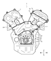
- FIG. 2 is a diagram showing a timing belt in an internal combustion engine and a belt cover arranged inside the timing belt;
- FIG. 4 is a diagram showing a belt cover arranged outside the timing belt in the internal combustion engine;
- FIG. 4 is a side view of the internal combustion engine showing a state in which the belt cover is attached;
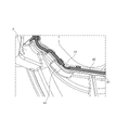
- FIG. 4 is a view showing the belt cover with the upper outer cover removed; It is a figure which shows the sealing structure of the mating surface of an upper outer cover, a lower outer cover, and a front inner cover. It is a figure which shows the seating part which the lower end part of a sealing member seats. It is a figure which shows the sealing structure in the back surface of a front inner cover.
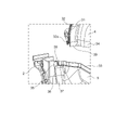
- FIG. 4 is a view showing an opening of a front inner cover and ribs for preventing foreign matter from entering;
- FIG. 1 shows a timing belt TB in an internal combustion engine 1 and a belt cover arranged inside the timing belt TB.
- FIG. 2 shows a belt cover arranged outside the timing belt TB in the internal combustion engine 1.
- the inner side and the outer side here refer to the side closer to the cylinder head CH, CH or the cylinder block CB of the internal combustion engine 1 with respect to the timing belt TB as the inner side, and the opposite side to the outer side.
- crankshaft 10 and camshafts 11, 12, 13, and 14 are arranged so as to protrude from cylinder heads CH, CH and cylinder block CB on one side of the internal combustion engine 1 .
- Crankshaft 10 and camshafts 11, 12, 13 and 14 are connected to drive pulleys 15, 16, 17, 18 and 19, respectively.
- a timing belt TB is stretched over the drive pulleys 15, 16, 17, 18, 19 and other pulleys.
- the timing belt TB is protected by a belt cover.
- the belt cover is attached to one side surface of the internal combustion engine body.
- the belt cover of this embodiment includes a front inner cover 2, a rear inner cover 3, an upper outer cover 4, a lower outer cover 5, a rear outer cover 7, a side mount bracket 8, and a lower cover 9. have.
- the lower cover 9 is attached around the crankshaft 10, and the side mount bracket 8 is attached above and adjacent to the lower cover 9.
- the rear outer cover 7 is then mounted above and adjacent to the side mount bracket 8, covering the outside of the drive pulleys 18, 19 of the camshafts 13, 14.
- the lower outer cover 5 is attached above and adjacent to the side mount bracket 8
- the upper outer cover 4 is attached above and adjacent to the lower outer cover 5 .
- the upper outer cover 4 and the lower outer cover 5 together constitute a front outer cover 6 that covers the outer sides of the drive pulleys 16 and 17 of the camshafts 11 and 12 .
- the front outer cover 6 is arranged forward of the rear outer cover 7 .
- Fig. 3 is a side view of the internal combustion engine 1 showing a state in which the belt cover is assembled.
- a crank pulley 20 is connected to the crankshaft 10
- a pipe 21 is arranged outside the front outer cover 6 and the rear outer cover 7, and a side A pipe 22 is arranged outside the mount bracket 8 .
- the front outer cover 6 is composed of the upper outer cover 4 and the lower outer cover 5 .
- the lower end of the lower outer cover 5 is provided with a recessed groove (not shown) for attachment to the side mount bracket 8. This recessed groove is inserted into the seal member accommodation groove at the upper end of the side mount bracket 8.
- a seal in the vertical direction is formed by fitting the housed seal member (none of which is shown).
- Both sides of the lower outer cover 5 are provided with concave grooves 37 for attachment to the front inner cover 2 . By engaging portion 38 an axial seal is formed. Further, the lower outer cover 5 is fixed to the front inner cover 2 using fastening members such as bolts.
- the lower end of the upper outer cover 4 is provided with a recessed groove 34 for attachment to the lower outer cover 5 . to form a vertical seal.
- a mating surface for attachment to the front inner cover 2 and the cylinder head CH is formed on the outer peripheral portion other than the lower end portion of the upper outer cover 4, and the sealing member 32 is accommodated in this mating surface.
- a seal member accommodating groove 31 is formed for this purpose.
- the front inner cover 2 and the cylinder head CH are formed with mating surfaces corresponding to the mating surfaces of the upper outer cover 4. By pressing the sealing member 32 of the upper inner cover 4 against these mating surfaces, the axial A seal is formed. Further, the upper outer cover 4 is fixed to the cylinder head CH using fastening members such as bolts.
- FIG. 4 is a perspective view showing the belt cover with the upper outer cover 4 removed.
- the oil seals of the camshafts 11 and 12, the timing belt TB, etc. can be inspected very easily. be able to.
- FIG. 5 is a perspective view of the mating surfaces of the upper outer cover 4, the lower outer cover 5, and the front inner cover 2 in this embodiment, viewed from the inside.
- the convex portion 33 of the upper end portion of the lower outer cover 5 is formed over substantially the entire upper end portion of the lower outer cover 5 , and both left and right ends thereof are provided for attachment to the front inner cover 2 . It has a shape with a slightly increased thickness in the vicinity of the concave groove 37 .
- the convex portions 38 provided on both sides of the front inner cover 2 extend to the vicinity of the upper end portion of the front inner cover 2 to form a projecting portion 35.
- the upper surface of the projecting portion 35 It is formed so as to be flush with the upper surface of the end portion of the convex portion 33 of the cover 5 .
- the end of the convex portion 33 of the lower outer cover 5 is arranged adjacent to the protruding portion 35 of the front inner cover 2, and the flush upper surfaces of the two form a flat surface.
- This flat surface functions as a seat portion 36 on which the lower end portion 32a of the seal member 32 accommodated in the seal member accommodation groove 31 of the upper outer cover 4 is seated.
- the convex portions 38 provided on both sides of the front inner cover 2 extend to the vicinity of the upper end portion of the front inner cover 2 to constitute the protruding portion 35, and the lower outer cover 5 is formed.
- the seating portion 36 is configured together with the end portion of the convex portion 33 , for example, in the case where the convex portion 38 is replaced with another sealing structure such as a concave groove, the lower outer cover 5 A protruding portion for forming the seat portion 36 together with the end portion of the protruding portion 33 may be separately provided.
- the end portion of the sealing member accommodation groove 31 provided in the outer peripheral portion of the upper outer cover 4 is formed continuously with the end portion of the recessed groove 34 provided in the lower end portion. That is, the wall portion forming the seal member housing groove 31 extends to a continuous portion 39 that intersects with the end portion of the recessed groove 34, and from there extends over substantially the entire lower end portion as the wall portion forming the recessed groove 34. exist.
- a lower end portion 32a of the sealing member 32 is formed wider than other portions.
- the lower end portion 32a of the sealing member 32 can be stably seated on the seating portion 36, so that high sealing performance can be obtained.
- the end portion of the sealing member accommodating groove 31 is formed wider than the other portion so that the wider lower end portion 32a can be accommodated.
- the lower end portion of the wall portion constituting the groove is located closer to the lower outer cover 5 than the position where the lower end portion 32a of the sealing member 32 is accommodated (that is, , and downward). Therefore, when the upper outer cover 4 is attached to the lower outer cover 5 and the front inner cover 2, the walls of the seal member accommodating groove 31 restrict the movement and deformation of the lower end 32a of the seal member 32. It can be seated on the seat 36 in a suitable position, orientation and shape.
- FIG. 6 is a perspective view of the seating portion 36 as seen from the rear.
- the upper surface of the protruding portion 35 of the front inner cover 2 does not protrude so as to form an angle with the wall portion of the front inner cover 2, but is formed continuously from the wall portion of the front inner cover 2 to form a gently curved surface. It is As a result, when the seal member 32 is seated on the seat portion 36, the seal member 32 and the seat portion 36 are brought into closer contact with each other, so that a gap can be prevented and a high sealing performance can be obtained.
- FIG. 7 is a rear view of the front inner cover 2 viewed from the back side in the axial direction toward the front side.
- the positions of the cam shafts 11 and 12 projecting into the belt cover are indicated by dashed lines.
- the upper end of the front inner cover 2 has a shape along cam shafts 11 and 12 arranged above the front inner cover 2 .
- the wall portion forming the back seal member accommodating groove 41 of the front inner cover 2 functions as a guide portion that guides leaked oil to an opening portion 43, which will be described later.
- the oil leaking from the oil seals of the camshafts 11 and 12 drops onto the upper wall portion of the back seal member accommodation groove 41 of the front inner cover 2 arranged directly below.
- the fallen oil is guided to the opening 43 formed at the lowermost position of the back seal member accommodation groove 41 through a plurality of inclined surfaces provided in the back seal member accommodation groove 41 .
- FIG. 8 is an enlarged view showing the structure around the opening 43 of the front inner cover 2.
- the opening 43 is formed by cutting out a part of the back seal member 42 accommodated in the back seal member accommodation groove 41 .
- the oil flowing along the inclined surface of the back seal member housing groove 41 is discharged to the outside of the belt cover through the opening 43 .
- the size of the opening 43 that is, the size of the notch provided in the back seal member 42, be the minimum size that allows the guided oil to smoothly pass through. Moreover, it is desirable to form the opening 43 as an opening in the vertical direction. By setting the size and orientation of the opening 43 in this manner, it is possible to minimize foreign matter such as water and dust from entering the interior of the belt cover through the opening 43 .
- a position facing the opening 43 of the front inner cover 2 that is, a position substantially directly below the opening 43 on the back surface of the front inner cover 2 is provided.
- the ribs 44 extend to cover the openings 43 from below to the sides, thereby preventing foreign matter from entering through the openings 43 .
- the rib 44 does not completely close the opening 43, and the gap between the rib 44, the rear sealing member accommodation groove 41, and the cylinder head CH is large. is set with a predetermined amount of clearance. Therefore, the oil discharged from the openings 43 can be smoothly discharged to the outside along the edges of the ribs 44. Intrusion can be effectively prevented by shielding the opening 43 by .
- the top surface of the end portion of the projecting portion 35 formed on the front inner cover 2 and the top surface of the end portion of the convex portion 33 of the lower outer cover 5 are formed flush with each other.
- the adjacent arrangement forms a planar seat 36 for the seal member 32 .
- the sealing member 32 can be seated on the seating portion 36 stably and with excellent sealing performance, so that the composite mating surfaces of the upper outer cover 4, the lower outer cover 5, and the front inner cover 2 can be secured. It is possible to provide a seal structure for a belt cover of an internal combustion engine that is excellent in sealing performance in
- the lower end portion of the wall portion constituting the groove is connected to the seal member 32 .
- the lower end 32a of the sealing member 32 is accommodated in the groove by extending toward the lower outer cover 5 side from the position where the lower end 32a is accommodated.
- the oil discharged from the camshafts 11 and 12 is guided to the opening 43 by the back seal member accommodation groove 41 formed in the back surface of the front inner cover 2 and discharged to the outside.
- the ribs 44 can prevent foreign matter from entering the belt cover from the outside. Therefore, it is possible to provide a seal structure for a belt cover of an internal combustion engine that can properly discharge the oil discharged from the camshafts 11 and 12 to the outside and effectively prevent foreign matter from entering.
- the timing belt TB is used as the transmission belt for transmitting the driving force from the crankshaft 10 to the camshafts 11, 12, 13, 14, but it is not limited to this.
- a chain transmission mechanism may be employed in which a transmission belt made up of a timing chain is stretched over a crankshaft drive wheel and a camshaft driven wheel made up of sprockets.
Landscapes
- Engineering & Computer Science (AREA)
- General Engineering & Computer Science (AREA)
- Mechanical Engineering (AREA)
- Chemical & Material Sciences (AREA)
- Combustion & Propulsion (AREA)
- Cylinder Crankcases Of Internal Combustion Engines (AREA)
Priority Applications (2)
| Application Number | Priority Date | Filing Date | Title |
|---|---|---|---|
| US18/557,074 US12037959B1 (en) | 2021-04-30 | 2022-04-25 | Seal structure of belt cover for internal combustion engine |
| JP2023517502A JP7470865B2 (ja) | 2021-04-30 | 2022-04-25 | 内燃機関のベルトカバーのシール構造 |
Applications Claiming Priority (2)
| Application Number | Priority Date | Filing Date | Title |
|---|---|---|---|
| JP2021-077127 | 2021-04-30 | ||
| JP2021077127 | 2021-04-30 |
Publications (1)
| Publication Number | Publication Date |
|---|---|
| WO2022230799A1 true WO2022230799A1 (ja) | 2022-11-03 |
Family
ID=83847211
Family Applications (1)
| Application Number | Title | Priority Date | Filing Date |
|---|---|---|---|
| PCT/JP2022/018689 Ceased WO2022230799A1 (ja) | 2021-04-30 | 2022-04-25 | 内燃機関のベルトカバーのシール構造 |
Country Status (3)
| Country | Link |
|---|---|
| US (1) | US12037959B1 (https=) |
| JP (1) | JP7470865B2 (https=) |
| WO (1) | WO2022230799A1 (https=) |
Cited By (1)
| Publication number | Priority date | Publication date | Assignee | Title |
|---|---|---|---|---|
| JP2024101699A (ja) * | 2023-01-18 | 2024-07-30 | 株式会社豊田自動織機 | 内燃機関 |
Citations (4)
| Publication number | Priority date | Publication date | Assignee | Title |
|---|---|---|---|---|
| JPS6247751U (https=) * | 1985-09-10 | 1987-03-24 | ||
| JPH08158886A (ja) * | 1994-12-06 | 1996-06-18 | Honda Motor Co Ltd | エンジンの付属品締結構造 |
| JPH08210511A (ja) * | 1995-02-06 | 1996-08-20 | Toyota Motor Corp | 段付合わせ面のシール構造 |
| US20170292601A1 (en) * | 2016-04-08 | 2017-10-12 | Hyundai Motor Company | Timing belt cover assembly for vehicle |
Family Cites Families (6)
| Publication number | Priority date | Publication date | Assignee | Title |
|---|---|---|---|---|
| JPS61179351U (https=) | 1985-04-30 | 1986-11-08 | ||
| US4998515A (en) * | 1990-04-20 | 1991-03-12 | Kcr Engine Automotive Parts, Inc. | Internal combustion engine timing chain cover |
| US5445547A (en) * | 1992-05-22 | 1995-08-29 | Honda Giken Kogyo Kabushiki Kaisha | Outboard motor |
| US20110227295A1 (en) * | 2008-11-25 | 2011-09-22 | Nok Corporation | Two-material composite gasket |
| US8454401B2 (en) * | 2008-12-12 | 2013-06-04 | Honda Motor Co., Ltd. | Outboard motor |
| JP6671224B2 (ja) * | 2016-04-14 | 2020-03-25 | 株式会社マーレ フィルターシステムズ | 内燃機関のシール構造 |
-
2022
- 2022-04-25 WO PCT/JP2022/018689 patent/WO2022230799A1/ja not_active Ceased
- 2022-04-25 JP JP2023517502A patent/JP7470865B2/ja active Active
- 2022-04-25 US US18/557,074 patent/US12037959B1/en active Active
Patent Citations (4)
| Publication number | Priority date | Publication date | Assignee | Title |
|---|---|---|---|---|
| JPS6247751U (https=) * | 1985-09-10 | 1987-03-24 | ||
| JPH08158886A (ja) * | 1994-12-06 | 1996-06-18 | Honda Motor Co Ltd | エンジンの付属品締結構造 |
| JPH08210511A (ja) * | 1995-02-06 | 1996-08-20 | Toyota Motor Corp | 段付合わせ面のシール構造 |
| US20170292601A1 (en) * | 2016-04-08 | 2017-10-12 | Hyundai Motor Company | Timing belt cover assembly for vehicle |
Cited By (1)
| Publication number | Priority date | Publication date | Assignee | Title |
|---|---|---|---|---|
| JP2024101699A (ja) * | 2023-01-18 | 2024-07-30 | 株式会社豊田自動織機 | 内燃機関 |
Also Published As
| Publication number | Publication date |
|---|---|
| US12037959B1 (en) | 2024-07-16 |
| US20240218843A1 (en) | 2024-07-04 |
| JPWO2022230799A1 (https=) | 2022-11-03 |
| JP7470865B2 (ja) | 2024-04-18 |
Similar Documents
| Publication | Publication Date | Title |
|---|---|---|
| US8567790B2 (en) | Sealing structure using metal gasket | |
| US12140106B2 (en) | Belt cover structure for internal combustion engine | |
| WO2022230799A1 (ja) | 内燃機関のベルトカバーのシール構造 | |
| US4729348A (en) | Cylinder head structure for V-type engine | |
| CN109072836B (zh) | 发动机装置 | |
| WO2016171211A1 (ja) | エンジンの補機取付構造 | |
| JP7609979B2 (ja) | 内燃機関のベルトカバー構造 | |
| US12031499B1 (en) | Seal structure and mounting method of belt cover for internal combustion engine | |
| CN1904320B (zh) | 发动机排气通道连接结构 | |
| JP4245447B2 (ja) | ケース部材の取付け構造 | |
| CN101377147B (zh) | 强制空冷式内燃机 | |
| AU2023200209B2 (en) | Internal combustion engine | |
| US7004118B2 (en) | Water pump for internal combustion engine | |
| JP5145055B2 (ja) | 内燃機関におけるバルブタイミング可変装置 | |
| JP3633098B2 (ja) | 内燃機関のチェーンカバー取付部構造 | |
| JPH0791249A (ja) | 部材取付構造および内燃機関のウォータポンプ取付構造 | |
| JP4433808B2 (ja) | エンジンの前部構造 | |
| WO2018092827A1 (ja) | エンジンのオイル通路構造 | |
| JP3738904B2 (ja) | 内燃機関 | |
| JP4478703B2 (ja) | 船外機 | |
| JP4187741B2 (ja) | チェーンケースの取付構造 | |
| US4762111A (en) | Head cover arrangement for double overhead cam type engine | |
| KR20080060659A (ko) | 타이밍 체인 커버용 개스킷 | |
| JPH0217170Y2 (https=) | ||
| JP2023072121A (ja) | 内燃機関のチェーンケース |
Legal Events
| Date | Code | Title | Description |
|---|---|---|---|
| 121 | Ep: the epo has been informed by wipo that ep was designated in this application |
Ref document number: 22795712 Country of ref document: EP Kind code of ref document: A1 |
|
| WWE | Wipo information: entry into national phase |
Ref document number: 18557074 Country of ref document: US |
|
| WWE | Wipo information: entry into national phase |
Ref document number: 2023517502 Country of ref document: JP |
|
| NENP | Non-entry into the national phase |
Ref country code: DE |
|
| 122 | Ep: pct application non-entry in european phase |
Ref document number: 22795712 Country of ref document: EP Kind code of ref document: A1 |