WO2022230376A1 - 積層コア、回転電機、積層コア製造装置、積層コアの製造方法および回転電機の製造方法 - Google Patents
積層コア、回転電機、積層コア製造装置、積層コアの製造方法および回転電機の製造方法 Download PDFInfo
- Publication number
- WO2022230376A1 WO2022230376A1 PCT/JP2022/010292 JP2022010292W WO2022230376A1 WO 2022230376 A1 WO2022230376 A1 WO 2022230376A1 JP 2022010292 W JP2022010292 W JP 2022010292W WO 2022230376 A1 WO2022230376 A1 WO 2022230376A1
- Authority
- WO
- WIPO (PCT)
- Prior art keywords
- laminated core
- core
- thin
- thin plate
- laminated
- Prior art date
- Legal status (The legal status is an assumption and is not a legal conclusion. Google has not performed a legal analysis and makes no representation as to the accuracy of the status listed.)
- Ceased
Links
Images









Classifications
-
- H—ELECTRICITY
- H02—GENERATION; CONVERSION OR DISTRIBUTION OF ELECTRIC POWER
- H02K—DYNAMO-ELECTRIC MACHINES
- H02K15/00—Processes or apparatus specially adapted for manufacturing, assembling, maintaining or repairing of dynamo-electric machines
- H02K15/02—Processes or apparatus specially adapted for manufacturing, assembling, maintaining or repairing of dynamo-electric machines of stator or rotor bodies
-
- H—ELECTRICITY
- H01—ELECTRIC ELEMENTS
- H01F—MAGNETS; INDUCTANCES; TRANSFORMERS; SELECTION OF MATERIALS FOR THEIR MAGNETIC PROPERTIES
- H01F3/00—Cores, Yokes, or armatures
- H01F3/02—Cores, Yokes, or armatures made from sheets
-
- H—ELECTRICITY
- H01—ELECTRIC ELEMENTS
- H01F—MAGNETS; INDUCTANCES; TRANSFORMERS; SELECTION OF MATERIALS FOR THEIR MAGNETIC PROPERTIES
- H01F41/00—Apparatus or processes specially adapted for manufacturing or assembling magnets, inductances or transformers; Apparatus or processes specially adapted for manufacturing materials characterised by their magnetic properties
- H01F41/02—Apparatus or processes specially adapted for manufacturing or assembling magnets, inductances or transformers; Apparatus or processes specially adapted for manufacturing materials characterised by their magnetic properties for manufacturing cores, coils, or magnets
- H01F41/0206—Manufacturing of magnetic cores by mechanical means
- H01F41/0233—Manufacturing of magnetic circuits made from sheets
- H01F41/024—Manufacturing of magnetic circuits made from deformed sheets
Definitions
- This application relates to a laminated core, a rotating electric machine, a laminated core manufacturing apparatus, a method for manufacturing a laminated core, and a method for manufacturing a rotating electric machine.
- a laminated core in which thin cores made of electromagnetic steel sheets are laminated is sometimes used as a stator core and a rotor core of a rotating electric machine.
- the laminated core is manufactured by cutting out a thin core group in which thin cores are laminated to have a predetermined thickness.
- a cutting blade for cutting out a laminated core in a direction perpendicular to the stacking direction of a group of thin cores a receiving blade arranged at a position opposite to the cutting blade with the group of thin cores sandwiched therebetween, and a cutting blade.
- Japanese Laid-Open Patent Publication No. 2002-100000 discloses a laminated core manufacturing apparatus including an adjusting device for adjusting the position of a group of thin plate cores in the laminating direction before cutting out such that the laminated core has a predetermined thickness.
- the present application has been made to solve the above-described problems, and aims to provide a laminated core manufacturing apparatus capable of preventing deformation of laminated cores cut out from a group of thin plate cores.
- a laminated core manufacturing apparatus of the present application is a laminated core manufacturing apparatus that cuts out a laminated core formed by laminating thin cores from a thin core group in which thin cores are laminated, and cuts out a laminated core group in the lamination direction of the thin core group.
- a stopper that regulates the position, a fixed guide that regulates the position of the group of thin plate cores in the direction perpendicular to the stacking direction, and a fixed guide that is provided with a gap in the direction of stacking and the group of thin plate cores in the direction perpendicular to the stacking direction.
- a cutting guide that regulates the position and moves in a direction perpendicular to the stacking direction to cut out the laminated core from the group of thin cores is provided.
- the laminated core manufacturing apparatus of the present application includes a fixed guide that regulates the position of the thin core group in the direction perpendicular to the lamination direction, and a thin core group that is provided with a gap in the lamination direction from the fixed guide and in the direction perpendicular to the lamination direction. and a cutting guide that moves in a direction orthogonal to the stacking direction and cuts out the laminated core from the group of thin plate cores. .
- FIG. 1 is a perspective view of a laminated core manufacturing apparatus according to Embodiment 1.
- FIG. 2 is a top view of the laminated core manufacturing apparatus according to Embodiment 1.
- FIG. 1 is a side view of a laminated core manufacturing apparatus according to Embodiment 1.
- FIG. 2 is an enlarged view of the laminated core manufacturing apparatus according to Embodiment 1.
- FIG. 4 is a diagram showing a step of cutting out a laminated core according to Embodiment 1;
- FIG. 4 is a diagram showing a step of discharging a laminated core according to Embodiment 1;
- 1 is a schematic diagram of an apparatus in which the laminated core manufacturing apparatus of Embodiment 1 and a pressing apparatus are combined.
- FIG. 2 is a top view of the laminated core manufacturing apparatus according to Embodiment 1.
- FIG. 2 is a top view of the laminated core manufacturing apparatus according to Embodiment 1.
- FIG. 4 is an explanatory view showing the operation of the laminated core manufacturing apparatus of Embodiment 1; 1 is a cross-sectional view of a rotating electric machine according to Embodiment 1;
- FIG. 10 is a perspective view of a laminated core manufacturing apparatus according to Embodiment 2;
- FIG. 10 is a top view of a laminated core manufacturing apparatus according to Embodiment 2;
- FIG. 10 is a side view of a laminated core manufacturing apparatus according to Embodiment 2;
- FIG. 8 is an enlarged view of a laminated core manufacturing apparatus according to Embodiment 2;
- FIG. 8 is a cross-sectional view of a laminated core manufacturing apparatus according to Embodiment 2;
- FIG. 10 is a diagram showing a step of discharging a laminated core according to Embodiment 2;
- FIG. 10 is a diagram showing a step of cutting out a laminated core according to Embodiment 2;
- FIG. 10 is a diagram showing a step of cutting out a laminated core according to Embodiment 2;
- FIG. 10 is an explanatory diagram showing a state when the laminated core is cut out according to the second embodiment;
- FIG. 11 is an enlarged view of a laminated core manufacturing apparatus according to Embodiment 3;
- FIG. 11 is an enlarged view of a laminated core manufacturing apparatus according to Embodiment 3;
- FIG. 1 is a perspective view of a laminated core manufacturing apparatus according to Embodiment 1.
- the laminated core manufacturing apparatus 1 of the present embodiment is composed of a base 2 and a cutting unit 3.
- the laminated core manufacturing apparatus 1 of the present embodiment has a function of cutting out laminated cores 32 of a predetermined length from a thin plate core group 31 that has been fed.
- the group of thin plate cores 31 is formed by laminating thin plate cores 31a made of, for example, electromagnetic steel sheets using a press machine.
- the cutting unit 3 can move on the base 2 along the stacking direction of the loaded thin plate core group 31 .
- the clipping unit 3 is composed of a fixed guide 4 , a clipping guide 5 , a stopper 6 and an ejection block 7 .
- the stacking direction of the thin core group 31 in the state of being loaded into the laminated core manufacturing apparatus 1 is defined as the x-axis direction
- the direction parallel to the surface of the base 2 perpendicular to the x-axis is defined as the y-axis direction
- a direction orthogonal to the x-axis and the y-axis is defined as the z-axis direction.
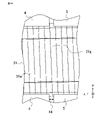
- FIG. 2 is a top view of the laminated core manufacturing apparatus 1 of the present embodiment as seen from the z-axis direction.
- FIG. 3 is a side view of the laminated core manufacturing apparatus 1 according to the present embodiment as seen from the x-axis direction.
- a groove 5a is formed in the fixed guide 4 and the cutting guide 5 along the x-axis direction such that a part of the periphery of the thin plate core 31a is embedded. Therefore, the thin core group 31 loaded into the laminated core manufacturing apparatus 1 is restricted in position in the y-axis direction by the grooves 5a formed in the fixed guide 4 and the cutting guide 5.
- FIG. 3 is a side view of the laminated core manufacturing apparatus 1 according to the present embodiment as seen from the x-axis direction.
- This groove 5a has a shape slightly larger than the outer shape of the thin plate core 31a, and when the thin plate core group 31 is inserted into the groove 5a of the fixed guide 4 and the cutting guide 5, there is a gap between the side wall of the groove 5a and the thin plate core group 31.
- a void occurs in the Further, as shown in FIG. 2, the fixed guide 4 and the cutting guide 5 are arranged with a gap in the x-axis direction. This gap is set to be equal to or less than the thickness of the thin plate core 31a.
- the movement of the fixed guide 4 in the y-axis direction is restricted.
- the cutting guide 5 can move in the y-axis direction.
- the stopper 6 is arranged so that a part of the tip of the thin plate core group 31 contacts. Also, as shown in FIG. 3, the stopper 6 is arranged at a position that does not hinder the movement of the cutting guide 5 in the y-axis direction.
- the ejection block 7 can move in the x-axis direction.
- a thin core group 31 is loaded into the laminated core manufacturing apparatus 1 along the x-axis direction.
- the thin plate core group 31 is inserted into the grooves 5 a of the fixed guide 4 and the cutting guide 5 until the tip of the thin plate core group 31 contacts the stopper 6 .
- a load is applied to the thin plate core group 31 toward the stopper 6 by a load application section (not shown).
- FIG. 4 is an enlarged view showing a gap separating the fixed guide 4 and the cutting guide 5 of the laminated core manufacturing apparatus 1 of the present embodiment.
- the gap between the fixed guide 4 and the cutting guide 5 is set to be equal to or less than the thickness of the thin plate core 31a. It is assumed that a cut 31b of the thin plate core group 31 exists between the gaps.
- FIG. 5 is a diagram showing a laminated core cutting process in the laminated core manufacturing apparatus 1 of the present embodiment. As shown in FIG. 5, the laminated core 32 can be cut out from the thin plate core group 31 by moving the cutting guide 5 in the y-axis direction. At this time, as shown in FIG.
- the thin core 31c closer to the fixed guide 4 than the cut 31b of the thin core group 31 is restricted from moving in the y-axis direction by the fixed guide 4.
- the thin plate core 31d closer to the cutting guide 5 than the cut 31b of the thin plate core group 31 moves together with the cutting guide 5 in the y-axis direction. In this manner, the laminated core 32 is cut out from the thin plate core group 31 along the cut line 31b.
- the gap 31b of the thin plate core group 31 does not exist between the gap separating the fixed guide 4 and the cut-out guide 5 depending on how the thin plate core group 31 is inserted.
- the load required to move the cutting guide 5 in the y-axis direction is measured, and if the load exceeds a certain value, the cutting operation is interrupted. Then, the load applied by the load application unit is adjusted, and the extraction operation is performed again. By repeating this operation, the extraction operation can be reliably executed.
- FIG. 6 is a diagram showing a laminated core discharging process in the laminated core manufacturing apparatus 1 of the present embodiment. As shown in FIG. 6, the cutting guide 5 moves in the y-axis direction and the discharge block 7 moves in the x-axis direction with respect to the cut-out laminated core 32, whereby the laminated core 32 is discharged from the laminated core manufacturing apparatus 1. can be done.
- the laminated core manufacturing apparatus 1 configured as described above provides the following five effects.
- the first effect is that deformation of the laminated core cut out from the group of thin cores can be prevented in the step of cutting out and discharging the laminated core. Since the fixed guide 4 and the cut-out guide 5 are formed with grooves 5a along the x-axis direction in which a part of the periphery of the thin core 31a is embedded, the thin core group 31 and the laminated core 32 are always aligned in the y-axis direction. position is regulated. Therefore, it is possible to prevent deformation of the laminated core 32 cut out from the thin core group 31 in the step of cutting out and discharging the laminated core. Furthermore, since the step of aligning the shape of the laminated core after cutting out the laminated core is not required, the productivity is improved.
- the second effect is that the core lamination factor of the thin core group is improved and warping of the thin core can be suppressed. Since a load is applied to the thin plate core group 31 toward the stopper 6 by the load applying portion, the core lamination factor of the thin plate core group 31 can be improved and warpage of the thin plate core 31a can be suppressed.
- the third effect is that the productivity of the laminated core cutting process is improved. Since the stopper 6 is arranged at a position that does not interfere with the movement of the cutting guide 5 in the y-axis direction, the stopper 6 does not interfere with the step of cutting out the laminated core. Therefore, the step of retracting the stopper 6 becomes unnecessary, thereby improving productivity.
- the fourth effect is that the equipment cost for the laminated core cutting process can be saved.
- the thin core group 31 is inserted into the cutting guide 5, there is a gap between the side wall of the groove 5a and the thin core group 31, so an impact load is applied to the thin core group 31 in the step of cutting out the laminated core. Therefore, the load required to move the cutting guide 5 in the y-axis direction in the cutting process is small, which saves equipment costs.
- the fifth effect is that in the step of cutting out the laminated core, it is possible to reduce the generation of shavings generated by rubbing between the thin plate core and the cutting guide and the wear of the cutting guide. Since the stopper 6 is arranged so as to contact a part of the tip of the thin plate core group 31, the amount of movement of the cutting guide 5 in the y-axis direction in the cutting process can be reduced. That is, the laminated core can be cut out simply by making the amount of movement of the cutting guide 5 in the y-axis direction larger than the length in the y-axis direction where the stopper 6 and the group of thin plate cores 31 are in contact with each other.
- the length in the y-axis direction of contact between the stopper 6 and the group of thin plate cores 31 is made as short as possible, the amount of movement of the cutting guide 5 in the y-axis direction in the cutting process can be reduced.
- the thin plate core 31c closer to the fixed guide 4 than the cut 31b rubs against the cutout guide 5, resulting in the generation of shavings and the cutout guide 5. wear can be reduced.
- the base 2 is positioned vertically below the cutting unit 3 .
- the shape of the groove 5a shown in FIG. 3 may be a shape that wraps around the core back portion of the thin plate core group 31 so that the thin plate core group 31 does not come off in the z-axis direction. With such a configuration, even if the base 2 is positioned vertically above the clipping unit 3, the operation is possible.
- FIG. 7 is a schematic diagram of an apparatus in which the laminated core manufacturing apparatus of the present embodiment and a pressing apparatus for thin core groups are combined.
- the lamination direction of the thin core group is set parallel to the direction of gravity, and the laminated core manufacturing apparatus 1 is arranged vertically below the pressing device 8 for the thin core group. Since the laminated core 32 cut out by the cutting guide 5 is discharged vertically downward by the force of gravity, the discharge block 7 may be omitted.
- the thin core group 31 is directly put into the laminated core manufacturing apparatus 1 from the pressing device 8 for the thin core group, the manufacturing process is simplified.
- the length of the cutting guide 5 in the x-axis direction is set larger than the maximum thickness of the laminated core 32 .
- the thickness of the laminated core cut out by this laminated core manufacturing apparatus is determined by the relative positions of the cutting guide 5 and the stopper 6 in the x-axis direction.
- the thickness of the laminated core 32 is adjusted using stoppers 6 having different lengths in the x-axis direction.
- the thickness of the laminated core 32 is adjusted by moving the position of the stopper 6 having the same length in the x-axis direction.
- the thickness of the laminated core can be adjusted by changing the stopper to a different length or by moving the position of the stopper having the same length. improves.
- the cutting unit 3 can move along the stacking direction of the thin core group 31, that is, along the x-axis direction.
- Laminated cores are continuously cut out from the group of thin cores by correlating the moving speed of the cutting unit 3 in the x-axis direction with the input speed in the x-axis direction of the group of thin cores 31 to be introduced into the laminated core manufacturing apparatus. be able to.
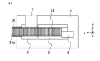
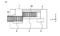
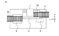
- FIG. 10 is an explanatory diagram showing the operation of continuously cutting out laminated cores from a group of thin plate cores in the laminated core manufacturing apparatus of the present embodiment.
- the thin core group 31 is inserted into the laminated core manufacturing apparatus 1 from the left along the x-axis direction.
- the tip of the thin plate core group 31 comes into contact with the stopper 6, cutting out of the laminated core is started.
- the cutting guide 5 moves upward along the y-axis direction to cut out the laminated core 32, and the ejection block 7 moves rightward along the x-axis direction.
- the laminated core 32 is ejected.
- the cutting unit 3 moves rightward along the x-axis direction on the base 2 at the same speed as the thin plate core group 31 is loaded in the x-axis direction.
- the cutting guide 5 and the discharge block 7 return to their initial positions.
- the cutting unit 3 moves rightward along the x-axis direction at the same speed as the thin plate core group 31 is loaded in the x-axis direction.
- the cutting unit 3 moves leftward along the x-axis on the base 2 and returns to the initial position. Then, as shown in FIG.
- the thin core group 31 is inserted into the laminated core manufacturing apparatus 1 from the left along the x-axis direction.
- the laminated core manufacturing apparatus of the present embodiment can continuously cut out laminated cores from a thin core group by repeating the operations shown in (a) to (d) of FIG. 10 .
- a certain value of load for moving the cutting guide 5 in the y-axis direction is set. If it exceeds, the cutting operation is interrupted, the load of the load applying unit is adjusted, and the cutting operation is performed again.
- the positional information of the cut 31b of the thin plate core group 31 is read by an image sensor or the like, and the stopper 6 is positioned so that the cut 31b is surely positioned between the gap between the fixed guide 4 and the cut-out guide 5. position can be adjusted. With such a configuration, there is no need to interrupt the cutting operation, and productivity is improved.
- FIG. 11 is a cross-sectional view of a rotating electrical machine using a laminated core manufactured by the laminated core manufacturing apparatus of this embodiment.
- the rotating electric machine 21 is composed of a rotor 22 that rotates, a stator 23 that generates force to rotate the rotor 22, and a frame 24 that fixes the stator 23 and supports the rotor 22 rotatably.
- the stator 23 is composed of a laminated core 32 and a coil 33 wound around the laminated core 32 via an insulating material.
- the thin plate core group is coated with an adhesive on the side surface of the thin plate core group so that the laminated thin plate cores do not separate.
- the laminated core manufacturing apparatus according to the second embodiment cuts out laminated cores from a group of thin cores having adhesive layers made of adhesive on their side surfaces.
- FIG. 12 is a perspective view of a laminated core manufacturing apparatus according to this embodiment.
- the laminated core manufacturing apparatus 1 of this embodiment is composed of a base 2 and a cutting unit 3 .
- An adhesive layer 31 e is formed on the side surface of the thin plate core group 31 .
- the cutting unit 3 can move on the base 2 along the stacking direction of the loaded thin plate core group 31 .
- the cutting unit 3 is composed of a fixed guide 4, a cutting guide 5, a stopper 6, a cutting blade 9, and a receiving blade 10.
- the configurations of the fixed guide 4, the clipping guide 5 and the stopper 6 are the same as those of the fixed guide, the clipping guide and the stopper of the first embodiment, respectively.
- the x-axis, y-axis and z-axis in this embodiment are the same as in the first embodiment.
- FIG. 13 is a top view of the laminated core manufacturing apparatus 1 of the present embodiment as seen from the z-axis direction.
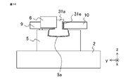
- FIG. 14 is a side view of the laminated core manufacturing apparatus 1 of the present embodiment as seen from the x-axis direction.
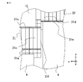
- FIG. 15 is an enlarged view showing a portion separating the cutting blade 9 and the receiving blade 10 of the laminated core manufacturing apparatus 1 of the present embodiment.
- 16 is a cross-sectional view taken along the line AA in FIG. 13.
- FIG. 13 is a top view of the laminated core manufacturing apparatus 1 of the present embodiment as seen from the z-axis direction.
- FIG. 14 is a side view of the laminated core manufacturing apparatus 1 of the present embodiment as seen from the x-axis direction.
- FIG. 15 is an enlarged view showing a portion separating the cutting blade 9 and the receiving blade 10 of the laminated core manufacturing apparatus 1 of the present embodiment.
- 16 is a cross-sectional view taken along the line AA in FIG. 13.
- the cutting blade 9 can move in the y-axis direction. Movement of the receiving blade 10 in the y-axis direction is restricted. Further, as shown in FIG. 15, the distance between the cutting blade 9 and the receiving blade 10 in the x-axis direction is set to be equal to or larger than the thickness of the thin plate core.
- the cutting blade 9 contacts the thin plate core 31d of the thin plate core group 31 when moved in the y-axis direction.
- the receiving blade 10 acts to prevent the thin plate core 31c positioned on the input side from the thin plate core 31d with which the cutting blade 9 is in contact with moving in the y-axis direction.
- the receiving blade 10 can eject the laminated core 32 from the laminated core manufacturing apparatus 1 by moving in the x-axis direction, like the ejection block shown in the first embodiment. As shown in FIG. 15, the distance between the fixed guide 4 and the cutting guide 5 in the x-axis direction is set wider than the distance between the cutting blade 9 and the receiving blade 10 in the x-axis direction.
- the cutting blade 9 has a projection 9a protruding toward the hole 5b formed in the cutting guide 5.
- a hole 5b formed in the cutting guide 5 has a structure having a width in the y-axis direction larger than that of the projection 9a of the cutting blade 9.
- the cutting guide 5 can move in the y-axis direction in conjunction with the movement of the cutting blade 9 in the y-axis direction.
- the thin core group 31 is fed into the laminated core manufacturing apparatus 1 along the x-axis direction.
- the thin plate core group 31 is inserted into the grooves 5 a of the fixed guide 4 and the cutting guide 5 until the tip of the thin plate core group 31 contacts the stopper 6 .
- the cutting blade 9 cuts out the laminated core 32 from the thin plate core group 31 by moving in the y-axis direction.
- the width of the hole 5b of the cutting guide 5 in the y-axis direction is larger than the width of the projection 9a of the cutting blade 9, so the cutting blade 9 contacts the thin plate core group 31 first.
- the projection 9a of the cutting blade 9 comes into contact with the side surface of the hole 5b of the cutting guide 5, and the cutting blade 9 and the cutting guide 5 interlock and move in the y-axis direction.
- the thin plate core group 31 contacted by the cutting blade 9 tries to move in the y-axis direction, but the thin plate core group 31 closer to the insertion side than the cutting blade 9 contacts the receiving blade 10 whose movement in the y-axis direction is restricted. In this manner, shearing force can be applied to the thin plate core group 31 by the load applied between the cutting blade 9 and the receiving blade 10 .
- FIG. 17 is a diagram showing a laminated core discharging process in the laminated core manufacturing apparatus 1 of the present embodiment.
- the receiving blade 10 moves in the x-axis direction with respect to the laminated core 32 that is cut out by the cutting blade 9 and the cutting guide 5 moving in the y-axis direction, thereby cutting the laminated core 32 into the laminated core manufacturing apparatus 1 . can be discharged from In this manner, the laminated core manufacturing apparatus of the present embodiment can reliably cut out laminated cores from a group of thin plate cores having adhesive layers formed on the side surfaces thereof.
- the gap in the y-axis direction between the fixed guide 4 and the cut-out guide 5 is set to be equal to or larger than the thickness of the thin plate core, a break in the thin plate core group 31 certainly exists in this gap. do. Therefore, the thin plate core is not caught in the gap between the fixed guide 4 and the cutting guide 5.
- the gap in the y-axis direction between the cutting blade 9 and the receiving blade 10 is set to be equal to or greater than the thickness of the thin plate core, the cutting blade 9 and the receiving blade 10 come into contact with the same thin plate core during cutting. No problem. Therefore, there is no need to adjust the positions of the cuts described in the first embodiment, and there is the advantage of improved productivity due to reduced facility costs and reduced tact time.
- FIG. 18A and 18B are explanatory diagrams of the cutting process in the case where the adhesive layer is not formed on the side surface of the thin core group 31 in the laminated core manufacturing apparatus of the present embodiment.
- the adhesive layer is not formed on the side surface of the thin core group 31, the thin core 31f between the thin core 31d with which the cutting blade 9 is in contact and the thin core 31c with which the receiving blade 10 is in contact is displaced from the thin core group 31. or may fall off. This is because the movement of the thin plate core 31f in the y-axis direction is not restricted by the receiving blade 10 or the fixed guide 4.
- FIG. 19 is an explanatory view of the cutting process when adhesive layers are formed on the side surfaces of the thin core group 31 in the laminated core manufacturing apparatus of the present embodiment.
- the adhesive layer 31e is sheared first at the cut between the thin plate cores 31f and 31d, the load applied to the cutting blade 9 is reduced. Therefore, the adhesive layer 31e at the gap between the thin core 31f and the thin core 31c is not sheared until the cutting is completed.
- the thin core 31f is fixed by the adhesive layer 31e. never This is the same even if the thin plate core group 31 has three or more cuts. Therefore, even if there are two or more slits 31b of the thin plate core group 31 between the cutting blade 9 and the receiving blade 10, the cutting can be completed without any problem.
- the cutting blade 9 and the receiving blade 10 contact the adhesive layer 31 e formed on the side surface of the thin plate core group 31 . If the cutting blade 9 and receiving blade 10 do not come into contact with the adhesive layer 31e, the adhesive layer may stretch before the adhesive layer is sheared, reducing the fixing force between the thin cores. By bringing the cutting blade 9 and the receiving blade 10 into contact with the adhesive layer 31e, it is possible to suppress the elongation of the adhesive layer in the portion that is not in contact with the cutting blade 9 and the receiving blade 10. FIG.
- the width of the hole 5b of the cutting guide 5 in the y-axis direction is larger than the width of the protrusion 9a of the cutting blade 9, an impact load is applied to the thin plate core group 31 in the step of cutting out the laminated core. Therefore, in the cutting process, the load required to move the cutting blade 9 in the y-axis direction can be reduced, which saves equipment costs.
- the thin core group has an adhesive layer formed on the side surface to fix the thin core.
- the thin cores may be fixed by providing an adhesive layer between the laminated thin cores constituting the thin core group.
- the thickness of the laminated core formed by bonding between laminations is determined by the number of laminated thin cores. Therefore, there is a problem that the thickness of the laminated core is not stable due to variations in the thickness of the thin core and the thickness of the adhesive layer.
- the thickness of the laminated core is determined not by the number of laminated thin cores but by the relative positions of the cutting guide and the stopper in the x-axis direction. The thickness of the laminated core can be stabilized without being affected by the thickness of the adhesive layer.
- FIG. 20 is an explanatory diagram showing a state in which laminated cores are cut out from a group of thin cores in which an adhesive layer is provided between laminated thin cores in the laminated core manufacturing apparatus of the present embodiment.
- FIG. 20 shows a state in which the adhesive layer 41 remains on the end surface 42 of the laminated core 32 after the laminated core 32 is cut out from the group of thin plate cores 31 .
- the thickness of the adhesive layer 41 is exaggerated.
- the actual thickness of the adhesive layer 41 is sufficiently smaller than the thickness of the thin plate core 31a.
- the adhesive layer 41 remains on at least one of the end face 42 of the cut laminated core 32 and the end face 43 of the thin plate core group 31 after the laminated core 32 is cut.
- the thin plate cores forming the thin plate core group may be fixed using caulking.
- the thickness of the laminated core fixed by caulking is determined by the number of laminated thin cores. Therefore, even in this laminated core, there is a problem that the thickness of the laminated core is not stable due to variations in the thickness of the thin plate core.
- the thickness of the laminated core is determined not by the number of laminated thin cores but by the relative positions of the cutting guide and the stopper in the x-axis direction. The thickness of the laminated core can be stabilized without being affected.
- the thin core group is in a state in which the thin core is tilted from the direction orthogonal to the stacking direction due to the influence of variations in the thickness of the thin core and the accuracy of the equipment that laminates the thin core to manufacture the thin core group.
- the laminated core manufacturing apparatus of Embodiment 3 can cut out laminated cores from a group of laminated thin cores in which the thin cores are inclined.
- the configuration of the laminated core manufacturing apparatus of the present embodiment is the same as the configuration of the laminated core manufacturing apparatus of the first embodiment. However, the gap in the x-axis direction between the fixed guide and the clipping guide is defined within a predetermined range.
- the thickness of the cut laminated core may vary.
- the fixed guide 4 and the cutting guide 5 are separated. It is conceivable that two cuts 31b of the thin plate core group 31 exist between the gaps. In this case, the laminated core is cut out from the group of thin plate cores at either of the two cuts 31b, and the thickness of the cut laminated core varies by the thickness of one sheet of the thin plate core.
- the gap between the fixed guide 4 and the cutting guide 5 in the x-axis direction is set to be equal to or less than the thickness of the thin core 31a. It is
- the gap 44 in the x-axis direction between the fixed guide 4 and the cutting guide 5 is equal to or more than half the thickness of the thin core 31a. is set to less than or equal to FIG. 21 is an enlarged view showing a portion separating the fixed guide 4 and the cutting guide 5 of the laminated core manufacturing apparatus of the present embodiment. If the distance between the fixed guide 4 and the cut-out guide 5 in the x-axis direction is reduced, the cut-out guide 5 moves in the y-axis direction when a group of thin cores with the thin cores tilted is fed into the laminated core manufacturing apparatus. can be difficult. For example, when the thin core is tilted as shown in FIG.
- the other end in the y-axis direction may be regulated by the cutting guide 5 . If the thin plate core 31g in such a state exists, it becomes difficult for the cutting guide 5 to move in the y-axis direction. In this case, as described in the first embodiment, the load required to move the cutting guide 5 in the y-axis direction is measured, and when the load exceeds a certain value, the cutting operation is interrupted. Then, the load applied by the load application unit is adjusted, and the extraction operation is performed again.
- FIG. 22 is an enlarged view showing a portion separating the fixed guide 4 and the clipping guide 5 when the load of the load applying portion is adjusted. As shown in FIG. 22, by repeating this operation until one end of the thin plate core 31g in the y-axis direction is not restricted by the fixed guide 4, the cutting operation can be performed reliably.
- the gap 44 between the fixed guide 4 and the cutting guide 5 in the x-axis direction is set to the thickness of the thin core 31a. , and less than or equal to the thickness of the thin plate core 31a.
- the laminated core manufacturing apparatus configured as described above even if a group of laminated thin cores is input with the thin cores inclined, the laminated cores can be reliably cut out without variation in the thickness of the laminated cores. .
- 1 Laminated core manufacturing device 2 Base, 3 Cutting unit, 4 Fixed guide, 5 Cutting guide, 5a Groove, 5b Hole, 6 Stopper, 7 Ejection block, 8 Press device, 9 Cutting blade, 9a Protrusion, 10 Receiving blade, 21 Rotating electric machine 22 rotor 23 stator 24 frame 31 thin plate core group 31a, 31c, 31d, 31f, 31g thin plate core 31b gap 31e adhesive layer 32 laminated core 33 coil 41 adhesive layer 42, 43 End face, 44 gap.
Landscapes
- Engineering & Computer Science (AREA)
- Power Engineering (AREA)
- Manufacturing & Machinery (AREA)
- Manufacture Of Motors, Generators (AREA)
- Manufacturing Cores, Coils, And Magnets (AREA)
Priority Applications (3)
| Application Number | Priority Date | Filing Date | Title |
|---|---|---|---|
| JP2023517116A JP7607753B2 (ja) | 2021-04-26 | 2022-03-09 | 積層コア製造装置、積層コアの製造方法および回転電機の製造方法 |
| CN202280027859.4A CN117157721A (zh) | 2021-04-26 | 2022-03-09 | 层叠铁芯、旋转电机、层叠铁芯制造装置、层叠铁芯的制造方法和旋转电机的制造方法 |
| DE112022002431.3T DE112022002431T5 (de) | 2021-04-26 | 2022-03-09 | Gestapelter Kern, elektrische Rotationsmaschine, Vorrichtung zur Herstellung eines gestapelten Kerns, Herstellungsverfahren für einen gestapelten Kern und Herstellungsverfahren für eine elektrische Rotationsmaschine |
Applications Claiming Priority (2)
| Application Number | Priority Date | Filing Date | Title |
|---|---|---|---|
| JP2021-073823 | 2021-04-26 | ||
| JP2021073823 | 2021-04-26 |
Publications (1)
| Publication Number | Publication Date |
|---|---|
| WO2022230376A1 true WO2022230376A1 (ja) | 2022-11-03 |
Family
ID=83848325
Family Applications (1)
| Application Number | Title | Priority Date | Filing Date |
|---|---|---|---|
| PCT/JP2022/010292 Ceased WO2022230376A1 (ja) | 2021-04-26 | 2022-03-09 | 積層コア、回転電機、積層コア製造装置、積層コアの製造方法および回転電機の製造方法 |
Country Status (4)
| Country | Link |
|---|---|
| JP (1) | JP7607753B2 (https=) |
| CN (1) | CN117157721A (https=) |
| DE (1) | DE112022002431T5 (https=) |
| WO (1) | WO2022230376A1 (https=) |
Citations (3)
| Publication number | Priority date | Publication date | Assignee | Title |
|---|---|---|---|---|
| JPS62120614A (ja) * | 1985-11-20 | 1987-06-01 | Alps Electric Co Ltd | 磁気ヘツド用ラミネ−トコアの製造装置 |
| JP2004023835A (ja) * | 2002-06-13 | 2004-01-22 | Denso Corp | 平板積層品の製造装置 |
| JP2005332976A (ja) * | 2004-05-20 | 2005-12-02 | Matsushita Electric Ind Co Ltd | 積層体の製造方法 |
Family Cites Families (3)
| Publication number | Priority date | Publication date | Assignee | Title |
|---|---|---|---|---|
| JP2003324869A (ja) | 2002-05-08 | 2003-11-14 | Daikin Ind Ltd | 電動機及び圧縮機 |
| JP2004055726A (ja) * | 2002-07-18 | 2004-02-19 | Denso Corp | 積層コア製造装置および積層コア製造方法 |
| JP6066936B2 (ja) | 2014-01-17 | 2017-01-25 | 三菱電機株式会社 | 積層鉄心の製造方法、固定子の製造方法 |
-
2022
- 2022-03-09 DE DE112022002431.3T patent/DE112022002431T5/de active Pending
- 2022-03-09 CN CN202280027859.4A patent/CN117157721A/zh active Pending
- 2022-03-09 WO PCT/JP2022/010292 patent/WO2022230376A1/ja not_active Ceased
- 2022-03-09 JP JP2023517116A patent/JP7607753B2/ja active Active
Patent Citations (3)
| Publication number | Priority date | Publication date | Assignee | Title |
|---|---|---|---|---|
| JPS62120614A (ja) * | 1985-11-20 | 1987-06-01 | Alps Electric Co Ltd | 磁気ヘツド用ラミネ−トコアの製造装置 |
| JP2004023835A (ja) * | 2002-06-13 | 2004-01-22 | Denso Corp | 平板積層品の製造装置 |
| JP2005332976A (ja) * | 2004-05-20 | 2005-12-02 | Matsushita Electric Ind Co Ltd | 積層体の製造方法 |
Also Published As
| Publication number | Publication date |
|---|---|
| JPWO2022230376A1 (https=) | 2022-11-03 |
| DE112022002431T5 (de) | 2024-02-15 |
| JP7607753B2 (ja) | 2024-12-27 |
| CN117157721A (zh) | 2023-12-01 |
Similar Documents
| Publication | Publication Date | Title |
|---|---|---|
| KR101035433B1 (ko) | 장방형 단면 와이어의 에지 방향 굽힘 가공 방법 및 굽힘 가공 장치 | |
| EP2778448B1 (en) | Radial foil bearing | |
| US20150256036A1 (en) | Laminated iron core and manufacturing method for laminated iron core | |
| JP2006353001A (ja) | 積層鉄心とその製造方法及び製造装置 | |
| CN102640397A (zh) | 层压铁心、具备该层压铁心的电动机及层压铁心的制造方法 | |
| WO2022230376A1 (ja) | 積層コア、回転電機、積層コア製造装置、積層コアの製造方法および回転電機の製造方法 | |
| US20190190330A1 (en) | Stacked core, device for manufacturing stacked core, and method of manufacturing stacked core | |
| JP3749490B2 (ja) | 積層鉄心およびその製造方法 | |
| EP3605808B1 (en) | Metal laminate and manufacturing method of metal laminate | |
| JP2010233436A (ja) | モータ | |
| US9538663B2 (en) | Combined wiring board and method for manufacturing combined wiring board | |
| CN110800190A (zh) | 层叠铁芯及其制造方法 | |
| JP2007228664A (ja) | 積層鉄心 | |
| WO2023145286A1 (ja) | 積層コア、回転電機、積層コアの製造方法、および、回転電機の製造方法 | |
| JPH09191614A (ja) | モータの鉄心、前記モータの鉄心の製造装置、及び前記モータの鉄心の製造方法 | |
| JP7154264B2 (ja) | コアエレメントの製造方法と製造装置 | |
| KR20190136528A (ko) | 필름 타발 장치 및 방법 | |
| JP2000254910A (ja) | グリーンシートの切断方法 | |
| KR20220066718A (ko) | 자동화 공정을 통해 생산성이 향상된 헤어핀 와인딩모터용 헤어핀 성형 장치 | |
| JP3782267B2 (ja) | 積層体の製造方法 | |
| JP7634852B2 (ja) | 接着剤付与装置、及び鋼板接着方法 | |
| KR102813626B1 (ko) | 적층코어 제조장치 및 제조방법 | |
| JPWO2022230376A5 (https=) | ||
| JP2017195669A (ja) | 回転電機の積層鉄芯およびその製造装置 | |
| KR20190136527A (ko) | 필름 타발 장치 및 방법 |
Legal Events
| Date | Code | Title | Description |
|---|---|---|---|
| 121 | Ep: the epo has been informed by wipo that ep was designated in this application |
Ref document number: 22795299 Country of ref document: EP Kind code of ref document: A1 |
|
| ENP | Entry into the national phase |
Ref document number: 2023517116 Country of ref document: JP Kind code of ref document: A |
|
| WWE | Wipo information: entry into national phase |
Ref document number: 112022002431 Country of ref document: DE |
|
| 122 | Ep: pct application non-entry in european phase |
Ref document number: 22795299 Country of ref document: EP Kind code of ref document: A1 |