WO2022230352A1 - 修正装置 - Google Patents
修正装置 Download PDFInfo
- Publication number
- WO2022230352A1 WO2022230352A1 PCT/JP2022/008841 JP2022008841W WO2022230352A1 WO 2022230352 A1 WO2022230352 A1 WO 2022230352A1 JP 2022008841 W JP2022008841 W JP 2022008841W WO 2022230352 A1 WO2022230352 A1 WO 2022230352A1
- Authority
- WO
- WIPO (PCT)
- Prior art keywords
- head
- stage
- unit
- moving
- pattern
- Prior art date
- Legal status (The legal status is an assumption and is not a legal conclusion. Google has not performed a legal analysis and makes no representation as to the accuracy of the status listed.)
- Ceased
Links
Images


Classifications
-
- G—PHYSICS
- G02—OPTICS
- G02F—OPTICAL DEVICES OR ARRANGEMENTS FOR THE CONTROL OF LIGHT BY MODIFICATION OF THE OPTICAL PROPERTIES OF THE MEDIA OF THE ELEMENTS INVOLVED THEREIN; NON-LINEAR OPTICS; FREQUENCY-CHANGING OF LIGHT; OPTICAL LOGIC ELEMENTS; OPTICAL ANALOGUE/DIGITAL CONVERTERS
- G02F1/00—Devices or arrangements for the control of the intensity, colour, phase, polarisation or direction of light arriving from an independent light source, e.g. switching, gating or modulating; Non-linear optics
- G02F1/01—Devices or arrangements for the control of the intensity, colour, phase, polarisation or direction of light arriving from an independent light source, e.g. switching, gating or modulating; Non-linear optics for the control of the intensity, phase, polarisation or colour
- G02F1/13—Devices or arrangements for the control of the intensity, colour, phase, polarisation or direction of light arriving from an independent light source, e.g. switching, gating or modulating; Non-linear optics for the control of the intensity, phase, polarisation or colour based on liquid crystals, e.g. single liquid crystal display cells
-
- H—ELECTRICITY
- H10—SEMICONDUCTOR DEVICES; ELECTRIC SOLID-STATE DEVICES NOT OTHERWISE PROVIDED FOR
- H10P—GENERIC PROCESSES OR APPARATUS FOR THE MANUFACTURE OR TREATMENT OF DEVICES COVERED BY CLASS H10
- H10P74/00—Testing or measuring during manufacture or treatment of wafers, substrates or devices
-
- Y—GENERAL TAGGING OF NEW TECHNOLOGICAL DEVELOPMENTS; GENERAL TAGGING OF CROSS-SECTIONAL TECHNOLOGIES SPANNING OVER SEVERAL SECTIONS OF THE IPC; TECHNICAL SUBJECTS COVERED BY FORMER USPC CROSS-REFERENCE ART COLLECTIONS [XRACs] AND DIGESTS
- Y02—TECHNOLOGIES OR APPLICATIONS FOR MITIGATION OR ADAPTATION AGAINST CLIMATE CHANGE
- Y02W—CLIMATE CHANGE MITIGATION TECHNOLOGIES RELATED TO WASTEWATER TREATMENT OR WASTE MANAGEMENT
- Y02W30/00—Technologies for solid waste management
- Y02W30/50—Reuse, recycling or recovery technologies
- Y02W30/82—Recycling of waste of electrical or electronic equipment [WEEE]
Definitions
- the present invention relates to a correction device.
- a granite surface plate is provided on nine anti-vibration mounts provided on a pedestal, a pair of guide bases are provided on the granite surface plate, and a Y direction is provided on the guide base to the granite surface plate.
- a gantry-type XY stage is disclosed which has a pair of pillars movable in the directions, a beam, a movement base movably in the X direction with respect to the beam, and a laser optical unit mounted on the movement base.
- a gantry-type XY stage like the invention described in Patent Document 1 is used for positioning.
- a linear encoder is used in the gantry-type XY stage, but since a positioning accuracy of several tens of ⁇ m is required, there is a problem that an expensive linear encoder must be used.
- the gantry-type XY stage such as the invention described in Patent Document 1, in order to accurately position the gantry that moves widely, it is necessary to increase the processing accuracy of the entire granite surface plate, which increases the manufacturing cost.
- the present invention has been made in view of such circumstances, and it is an object of the present invention to provide a correction device that can perform positioning with high accuracy without increasing manufacturing costs.
- a correction apparatus includes, for example, a first stage having a suction stage that suctions a substrate, a gantry provided above the suction stage, and a second stage provided on the gantry. two stages, a head provided on the second stage and having a correction head for correcting the substrate, a first moving section for changing a relative position of the first stage and the gantry in a first direction, the a second moving unit that changes relative positions of the first stage and the second stage in a second direction substantially orthogonal to the first direction; and a head moving unit that moves the head with respect to the second stage.
- the second stage has a first axis provided substantially along the first direction and a second axis provided substantially along the second direction
- the head moving section comprises: moving the head in the first direction along the first axis and moving the head in the second direction along the second axis; and the positioning accuracy of the second moving part.
- the head moving section moves the head along the first axis and the second axis provided on the second stage. Therefore, the moving distance of the head in the first direction by the head moving part is shorter than the moving distance in the first direction by the first moving part, and the moving distance of the head in the second direction by the head moving part is the second moving distance by the second moving part. Shorter than the travel distance in two directions. Further, the positioning accuracy of the head moving portion is higher than the positioning accuracy of the first moving portion and the positioning accuracy of the second moving portion. Therefore, the positioning accuracy of the first moving part and the second moving part and the machining accuracy (flatness, etc.) of the first stage can be lowered. Thereby, positioning can be performed with high accuracy without increasing the manufacturing cost.
- a first movement control section for controlling the first movement section and the second movement section
- the substrate has a pattern provided on a surface thereof, and the pattern is provided on the first stage.
- the first moving part and the second moving part having a first pattern provided substantially along the first direction and a second pattern provided substantially along the second direction in the state of each has a reading unit that reads the pattern
- the first movement control unit controls the first movement unit based on the result of reading the second pattern by the reading unit
- the reading unit You may control a said 2nd moving part based on the reading result of a said 1st pattern.
- the patterns are used instead of the scales, the glass scales are not required in the first moving part and the second moving part. Therefore, there is no need to use an expensive linear encoder, and manufacturing costs can be reduced.
- the first movement control unit acquires defect information that is information about the position of the defect on the substrate, and based on the defect information, a defect superimposition pattern that is a pattern that overlaps the defect among the patterns. may be specified, and the first moving unit and the second moving unit may be controlled to move the head over the defect superimposed pattern based on the number of the patterns read by the reading unit. As a result, the head can be placed near the defect without using a linear encoder.
- a second movement control section for controlling the head movement section is provided, the head has an image acquisition section for acquiring an image of the substrate, and the second movement control section is acquired by the image acquisition section.
- the head may be moved based on the obtained image. As a result, the head can be positioned with high accuracy.
- the first moving section and the second moving section may each use a linear motor using an electromagnetic force as a driving source, and the head moving section may use a piezo element as a driving source. Thereby, the head can be moved precisely.
- the positioning accuracy of the first moving section and the second moving section may be coarser than the pitch of the pattern, and the positioning accuracy of the head moving section may be finer than the pitch of the pattern. Thereby, the head can be moved precisely.
- positioning can be performed with high accuracy without increasing manufacturing costs.
- FIG. 1 is a front view showing an outline of a correction device 1;
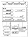
- FIG. 2 is a block diagram showing an electrical configuration of the correction device 1;
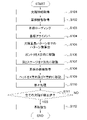
- FIG. 5 is a flow chart showing the flow of processing of the correction device 1;
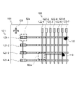
- 1 is a diagram schematically showing a part of a substrate 100;
- FIG. 1 is a diagram schematically showing a part of a substrate 100;
- a repairing device of the present invention is a device for repairing a defect found during the manufacturing process of a liquid crystal display device.
- a liquid crystal display device has a structure in which a liquid crystal is sandwiched between a pair of substrates.
- a color filter is formed by alternately coating resins in which blue, green, and red pigments are dispersed on one substrate, and the other substrate.
- An electronic circuit pattern is formed on the . Defects in color filters and electronic circuit patterns cause defects such as abnormal display. Therefore, in the repair device, the defects found by the inspection device are irradiated with laser light from the back surface of the substrate to repair the defects.
- the substrate to be repaired by the repair device is not limited to the liquid crystal display device.
- FIG. 1 is a perspective view showing an outline of the correction device 1 according to the first embodiment.
- FIG. 2 is a front view showing an outline of the correction device 1.
- the depth direction of the correction device 1 is defined as the X direction
- the direction orthogonal to the X direction on the horizontal plane is defined as the Y direction.
- a direction orthogonal to the X direction and the Y direction is defined as the Z direction (vertical direction).
- the correction apparatus 1 mainly includes a first stage 10, a gantry 20, a second stage 30, a head 40, a gantry moving section 50 (corresponding to the first moving section of the present invention), and a second stage moving section 60. (corresponding to the second moving section of the present invention) and a head moving section 70 .
- the first stage 10 mainly has a base 11 and a suction stage 12.
- the base 11 is a member that serves as a base for the adsorption stage 12 and the gantry 20, and is placed on a floor surface or the like.
- the base 11 is provided with a coarse movement X axis 13 substantially along the X direction.
- the coarse movement X-axis 13 is provided near the +Y side end and the ⁇ Y side end of the base 11, respectively.
- a gantry 20 is provided on the base 11 so as to cover the adsorption stage 12 .
- the suction stage 12 is a plate-like member having a substantially rectangular shape in plan view.
- a substrate 100 is placed on the upper surface (+z side surface) of the adsorption stage 12 .
- the adsorption stage 12 sucks air and adsorbs the substrate 100 to the adsorption stage 12 .
- the gantry 20 has a gate shape and covers the upper side of the adsorption stage 12 .
- the gantry 20 mainly has columns 21 and beams 22 provided on the columns 21 .
- the beam 22 is substantially bar-shaped and provided above the first stage 10 .
- the struts 21 are provided along the Z direction, and the beams 22 are provided along the Y direction.
- a protrusion 21 a is provided at the lower end of the support 21 .
- the convex portion 21 a is inserted into a concave portion 13 a provided on the coarse movement X-axis 13 .
- the concave portion 13a extends in the X direction, and the gantry 20 moves in the X direction as the convex portion 21a slides along the concave portion 13a.
- a second stage 30 is provided on the beam 22 .
- the beam 22 is also provided with a coarse movement Y axis 23 substantially along the Y direction.
- the second stage 30 is movable in the Y direction along the coarse movement Y axis 23 .
- a head 40 is provided on the second stage 30 .
- the head 40 has a correction head 44 (see FIG. 3) not shown.
- the correction head 44 has, for example, a laser light source and an optical member, and corrects the substrate 100 by emitting laser light emitted from the laser light source to the substrate 100 .
- the modification head 44 is not limited to a form that modifies the substrate 100 using laser light.
- the repair head includes a mode in which a disconnection of the substrate 100 is repaired by applying metal ink to the substrate 100 and baking the metal ink with light emitted from a lamp.
- the head 40 also has an image acquisition unit 45 (see FIG. 3).
- the image acquisition unit 45 has an magnifying optical system for magnified observation, an imaging device such as a CCD, a CMOS, and the like.
- the image captured by the image acquisition unit 45 is output to a display device (not shown) or the like.
- the image acquisition unit 45 can use, for example, an optical microscope or a charged particle beam microscope.
- a fine movement X-axis 31 and a fine movement Y-axis 32 are provided on the second stage 30 .
- the fine movement X axis 31 is provided substantially along the X direction
- the fine movement Y axis 32 is provided substantially along the Y direction.
- the second stage 30 is provided with a head moving section 70 that moves the head 40 with respect to the second stage 30 .
- the head moving unit 70 includes a piezoelectric element 71 (see FIG. 3) as a drive source for moving the head 40 along the fine movement X-axis 31 and a piezoelectric element 72 as a drive source for moving the head 40 along the fine movement Y-axis 32. (see FIG. 3).
- the driving source of the head moving unit 70 is not limited to the piezo element, and may be a linear motor or a servomotor, for example.
- the gantry moving unit 50 moves the gantry 20 in the X direction along the coarse movement X axis 13 .
- the gantry moving unit 50 has a linear motor 51 (see FIG. 3) that uses electromagnetic force as a drive source.
- the gantry moving unit 50 also has a reading unit 52 that reads the pattern provided on the substrate 100 .
- the reading unit 52 is provided on the column 21 and moves in the X direction as the gantry 20 moves in the X direction.
- the second stage moving section 60 moves the second stage 30 in the Y direction along the coarse movement Y axis 23 .
- the second stage moving unit 60 has a linear motor 61 (see FIG. 3) that uses electromagnetic force as a drive source.
- the second stage moving section 60 also has a reading section 62 that reads the pattern provided on the substrate 100 .
- the reading unit 62 is provided on the second stage 30 and moves in the Y direction as the second stage 30 moves in the Y direction.
- the moving distance of the head 40 in the X direction by the head moving unit 70 is shorter than the moving distance of the gantry 20 in the X direction by the gantry moving unit 50, and the moving distance of the head 40 in the Y direction by the head moving unit 70 is the second stage moving distance. It is shorter than the moving distance of the second stage 30 in the Y direction by the unit 60 .
- the moving distances of the head 40 in the X direction and the Y direction by the head moving unit 70 are each about 2 mm.
- the moving distance of the gantry 20 (the head 40 provided on the gantry 20) by the gantry moving unit 50 and the moving distance of the second stage 30 (the head 40 provided on the second stage 30) by the second stage moving unit 60 are , are each about 3000 mm.
- the movement distance of the head 40 in the X direction and the Y direction (the length of the fine movement X axis 31 and the fine movement Y axis 32) by the head movement section 70 is not limited to 2 mm.
- the moving distance of the head 40 by the head moving unit 70 depends on the accuracy of the inspection device that inspects the substrate 100 for defects. In this embodiment, since the accuracy of the inspection apparatus is within 1 mm, the moving distance of the head 40 in the X and Y directions by the head moving unit 70 is set to 2 mm (approximately twice the accuracy of the inspection apparatus).
- the moving speed of the head 40 in the X direction by the head moving unit 70 is lower than the moving speed of the gantry 20 in the X direction by the gantry moving unit 50, and the moving speed of the head 40 in the Y direction by the head moving unit 70 is the second stage moving speed. It is slower than the moving speed of the second stage 30 in the Y direction by the unit 60 .
- the moving speed of the head 40 in the X direction and the Y direction by the head moving unit 70 is about 1 ⁇ m per second.
- the moving speed of the gantry 20 (head 40) by the gantry moving unit 50 and the moving speed of the second stage 30 (head 40) by the second stage moving unit 60 are each about 2 mm per second.
- the positioning accuracy of the head moving section 70 is higher than the positioning accuracy of the gantry moving section 50 and the positioning accuracy of the second stage moving section 60 .
- the positioning accuracy of the head 40 in the X and Y directions is finer than the pixel pitch (the pitch of the patterns 121 and 122 (see FIG. 5)), and is about 0.1 ⁇ m in this embodiment.
- the positioning accuracy of the gantry moving unit 50 and the positioning accuracy of the second stage moving unit 60 are coarser than the pixel pitch, and are each about 10 ⁇ m in this embodiment.
- the correction device 1 moves the head 40 large, fast, and coarsely with the gantry moving unit 50 and the second stage moving unit 60, and moves the head 40 finely, slowly, and accurately with the head moving unit 70.
- FIG. 3 is a block diagram showing the electrical configuration of the correction device 1.
- the correction device 1 mainly includes a control section 101 , a storage section 102 , an input section 103 , an output section 104 and a communication section 105 .
- the control unit 101 is a program control device such as a CPU (Central Processing Unit), which is an arithmetic unit, and operates according to a program stored in the storage unit 102 .
- the control unit 101 will be detailed later.
- the control unit 101 also controls the suction stage 12, the correction head 44, the image acquisition unit 45, the gantry moving unit 50 (linear motor 51 and reading unit 52), the second stage moving unit 60 (linear motor 61 and reading unit 62), It is connected to the head moving section 70 (piezo elements 71 and 72) and the like.
- the storage unit 102 is a non-volatile memory, a volatile memory, or the like, holds programs and the like executed by the control unit 101 and operates as a substrate memory for the control unit 101 .
- the input unit 103 includes input devices such as a keyboard and mouse.
- the output unit 104 is a display or the like.
- the communication unit 105 acquires data from another device (for example, an inspection device) via a network board or a storage medium and transmits the data to the control unit 101, and also transmits data generated by the control unit 101 via a network board or the like. Send to other devices.
- the control unit 101 includes, as main functional units, a substrate suction unit 101a, an information acquisition unit 101b, a first movement control unit 101c, a second movement control unit 101d, a pattern reading unit 101e, an image processing unit 101f, and a correction processing unit 101g. is composed of
- the substrate adsorption unit 101 a controls the adsorption stage 12 to suck air while the substrate 100 is placed on the adsorption stage 12 and adsorb the substrate 100 to the upper side of the adsorption stage 12 .
- the information acquisition unit 101b acquires information about the substrate 100 (hereinafter referred to as substrate information) via the communication unit 105.
- the board information includes board design information such as the size of the board 100, the positions of the patterns, and the spacing between adjacent patterns (pattern pitch).
- the information acquisition unit 101 b also acquires information (hereinafter referred to as defect information) regarding the position of the defect on the substrate 100 via the communication unit 105 .
- the defect information is written in the substrate coordinate system, and the positions of the defects on the substrate 100 are indicated.
- the defect information is acquired by an inspection device (not shown) before processing by the repair device 1 .
- the first movement control unit 101c controls the gantry movement unit 50 to move the gantry 20 (head 40) in the X direction.
- the first movement control unit 101c also controls the second stage movement unit 60 to move the second stage 30 (head 40) in the Y direction.
- the processing performed by the first movement control unit 101c will be detailed later.
- the second movement control section 101d controls the head movement section 70 to move the head 40 with respect to the second stage 30 by minute distances in the X and Y directions. The processing performed by the second movement control unit 101d will be detailed later.
- the pattern reading unit 101e acquires the measurement results obtained by the reading units 52 and 62, and detects whether or not the patterns have been read by the reading units 52 and 62. For example, when using the optical camera type pattern reading unit 101e, the pattern is read based on the captured image. When the laser reflection type pattern reading unit 101e is used, the pattern is read by irradiating the substrate with laser light and detecting the laser light reflected by the metal (pattern). Further, when the capacitive coupling type pattern reading unit 101e is used, a capacitance type sensor is brought close to the substrate to apply a voltage, and the pattern is read using the fact that the capacitance changes only on the pattern.
- the optical camera type pattern reading unit 101e can handle speeds up to 100 mm/s, and the laser reflection type and capacitive coupling type pattern reading unit 101e can handle speeds up to 2 mm/s.
- the image processing unit 101f acquires the image of the substrate 100 obtained by the image acquisition unit 45, performs image processing, and extracts defects from the acquired image.
- the image acquisition unit 45 and the image processing unit 101f can observe the substrate 100 with a resolution of about 100 ⁇ m. Since the processing performed by the image processing unit 101f is general, the description thereof is omitted.
- the correction processing unit 101g controls the correction head 44 based on the image obtained by the image acquisition unit 45, and irradiates the substrate 100 with laser light. Since the processing performed by the correction processing unit 101g is general, the description thereof is omitted.
- FIG. 4 is a flow chart showing the flow of processing in which the repair apparatus 1 repairs defects in the substrate 100. As shown in FIG. 4
- the information acquisition unit 101b Prior to loading the substrate 100, the information acquisition unit 101b acquires defect information (step S101) and acquires substrate information (step S102). It should be noted that the order of processing steps S101 and S102 does not matter, and steps S101 and S102 may be performed simultaneously.
- step S103 when the substrate 100 is loaded onto the suction stage 12 by a loading/unloading unit (not shown) (step S103), the control unit 101 detects the alignment mark 123 (see FIG. 5) of the substrate 100 using a camera (not shown). Then, the substrate 100 is positioned, and after the positioning of the substrate 100, the substrate 100 is attracted to the upper side of the attraction stage 12 (step S104).
- the first movement control unit 101c coarsely moves the gantry 20 and the second stage 30 (moves coarsely, quickly, and far) (steps S105 to S107).
- the processing of steps S105 to S107 will be described in detail below.
- the first movement control unit 101c acquires substrate information and defect information via the information acquisition unit 101b. Based on the substrate information and the defect information, the first movement control unit 101c identifies a pattern that overlaps the defect (hereinafter referred to as a defect superimposed pattern).
- FIG. 5 is a diagram schematically showing part of the substrate 100.
- the substrate information includes information on the positions and sizes of the patterns 121 and 122 and the alignment marks 123 on the substrate 100 and the pitch of the patterns 121 and 122 .
- alignment marks 123 are provided near the corners of the substrate 100, and patterns 121 along the horizontal direction of FIG. 5 are arranged in the vertical direction of FIG.
- Patterns 122 along the direction are arranged in the horizontal direction of the paper surface of FIG.
- the pattern 121 has patterns 121-1, 121-2, 121-3, . 2, 122-3 . . .
- the defect information includes information about the position of the defect 110 on the substrate 100 .
- the defect information is based on the position of the alignment mark 123.
- the first movement control unit 101c determines where the defect 110 exists on the substrate 100 and which pattern is superimposed on the defect. Identify patterns. In the example shown in FIG. 5, the defect 110 is located in patterns 121-3 and 122-6, and the patterns 121-3 and 122-6 are defect superimposed patterns.
- the substrate 100 is placed on the suction stage 12 so that the vertical direction of FIG. 5 is along the X direction and the horizontal direction of FIG. 5 is along the Y direction.
- the first movement control unit 101c calculates the number of patterns 121 and 122 from the current position to the defect superimposed pattern.
- the number of patterns 121 and 122 is calculated based on the origin position (for example, the alignment mark 123) of the substrate 100.
- Step S106 Returning to the description of FIG.
- the first movement control unit 101c drives the linear motor 51 to move the gantry 20 in the X direction while acquiring the reading result of the pattern 121 by the reading unit 52 via the pattern reading unit 101e.
- the first movement control unit 101c moves the gantry 20 in the X direction until the reading unit 52 detects the number of patterns 121 calculated in step S104.
- the field of view of the reading unit 52 is indicated by 52a.
- the field of view 52a moves downward on the page of FIG. Since the number of patterns 121 up to the defect superimposed pattern is calculated to be three in step S105, the first movement control unit 101c keeps moving until the pattern reading unit 101e detects that the visual field 52a has detected the pattern 121 three times. , to move the gantry 20 in the -X direction. As a result, the beam 22 of the gantry 20, that is, the head 40 is placed on the defect superimposed pattern (pattern 121-3).
- Step S107 Returning to the description of FIG.
- the first movement control unit 101c drives the linear motor 61 to move the second stage 30 in the Y direction while acquiring the reading result of the pattern 122 by the reading unit 62 via the pattern reading unit 101e.
- the first movement control unit 101c moves the second stage 30 in the Y direction until the reading unit 62 detects the number of patterns 122 calculated in step S104.
- the field of view of the reading unit 62 is indicated by 62a.
- the field of view 62a moves rightward on the paper surface of FIG. Since the number of patterns 122 up to the defect superimposed pattern is calculated to be six in step S105, the first movement control unit 101c controls the pattern reading unit 101e to detect that the pattern 122 has been detected six times in the field of view 62a. , to move the second stage 30 in the +Y direction. As a result, the second stage 30, that is, the head 40 is placed on the defect superimposed pattern (pattern 122-6).
- the first movement control unit 101c moves the head 40 over the defect superimposed pattern based on the number of patterns 121, 122 read by the reading units 52, 62. , controls the gantry moving unit 50 and the second stage moving unit 60 .
- the second movement control unit 101d moves (finely moves) the head 40 by a minute distance in the X direction and the Y direction with respect to the second stage 30 (steps S108 and S109).
- steps S108 and S109 will be described in detail below.
- Step S108 The image processing unit 101f acquires the image obtained by the image acquisition unit 45, performs image processing, and extracts the defect 110 from the acquired image. Assuming that the pitch of the patterns 121 and 122 is 100 ⁇ m and the field of view of the image acquisition unit 45 is 2 mm 2 , since the head 40 is arranged above the defect superimposed pattern in steps S105 to S107, the image acquisition unit 45 A defect 110 is always included in the field of view.
- Step S109 The second movement control section 101d moves the head 40 in the X direction and the Y direction based on the image acquired by the image acquisition section 45.
- the second movement control unit 101d obtains the distance between the current position (the center of the image) and the defect 110 based on the image processing result obtained in step S108, and moves the piezoelectric elements 71 and 72 by the obtained distance. to move the head 40 .
- the head 40 is positioned with high precision so that the defect 110 is arranged at the center of the image obtained by the image acquisition unit 45 .
- the second movement control unit 101d moves the head 40 by a certain amount using the piezo elements 71 and 72, and the image processing unit 101f acquires the image obtained by the image acquisition unit 45 to extract the defect 110. You can repeat. That is, the second movement control unit 101d may repeat the processing of steps S108 and S109 until the defect is arranged at the center of the image obtained by the image acquisition unit 45.
- the correction processing unit 101g irradiates the substrate 100 with laser light based on the image obtained by the image acquisition unit 45 (step S110).
- the control unit 101 determines whether or not all defects included in the defect information acquired in step S101 have been corrected (step S110) (step S111). If correction processing has not been performed for all defects (NO in step S110), the control unit 101 returns the processing to step S105. When all defects have been repaired (YES in step S110), the control unit 101 stops the adsorption of the substrate 100 by the adsorption stage 12, and corrects the substrate 100 by a loading/unloading unit (not shown). The wafer is unloaded from the apparatus 1 (step S112), and the series of processing ends.
- the first movement control unit 101c calculates the number of patterns 121 and 122 based on the position of the defect on which the correction processing was last performed. For example, in the example shown in FIG. 5, when the defect 111 is processed after the defect 110, the number of patterns 121 and 122 up to the defect 111 is calculated with the position of the defect 110 as a reference.
- the defect superimposed patterns of the defect 111 are patterns 121-1 and 102-7. It is calculated that the number of patterns 122 from the defect superimposed pattern to the defect superimposed pattern of the defect 111 is one in the +Y direction. That is, when performing step S105 for the second time or later, the number of patterns 121 and 122 from the current position to the defect superimposed pattern is calculated, and the moving direction is obtained.
- the gantry 20 is provided with the second stage 30, the second stage 30 is provided with the head 40, the head 40 is roughly moved by the gantry moving section 50 and the second stage moving section 60, and the head moving section
- the head 40 is roughly moved by the gantry moving section 50 and the second stage moving section 60, and the head moving section
- the head 40 is roughly moved by the gantry moving section 50 and the second stage moving section 60
- the head moving section By precisely moving the head 40 at 70, highly accurate positioning can be performed without increasing the manufacturing cost of each component of the correction device 1.
- FIG. Specifically, by providing the fine movement X-axis 31 and the fine movement Y-axis 32 on the second stage 30, the positioning accuracy of the gantry moving unit 50 and the second stage moving unit 60, for example, the positioning accuracy of the linear motors 51 and 61 and the The machining accuracy (flatness, etc.) of one stage 10 can be lowered, thereby reducing the manufacturing cost.
- the first stage in a conventional gantry-type XY stage that uses a linear encoder, the first stage must be precisely machined over the length of the gantry and stage movement (approximately 3000 mm), increasing manufacturing costs.
- the fine movement X-axis 31 and the fine movement Y-axis 32 require precise machining, and since the length is as short as about 2 mm, the manufacturing cost can be reduced.
- a conventional gantry-type XY stage using a linear encoder must use a high-performance linear motor capable of high-precision positioning on the order of 0.1 ⁇ m, which increases manufacturing costs.
- the present embodiment does not require a high-performance linear motor, and can reduce manufacturing costs.
- the head can be moved while reducing the manufacturing cost.
- a high positioning accuracy can be maintained by the portion 70 .
- the head 40 is moved by the gantry moving unit 50 and the second stage moving unit 60 based on the results of reading the patterns 121 and 122 provided on the substrate 100 by the reading units 52 and 62.
- the gantry moving unit 50 and the second stage moving unit 60 do not need the glass scale. Therefore, there is no need to use an expensive linear encoder, and manufacturing costs can be reduced.
- Positioning using the patterns 121 and 122 provided on the substrate 100 is not possible with an exposure apparatus, a drawing apparatus, or the like, which processes a substrate having no pattern. 122 can be carried out only by the correction apparatus 1 that processes the substrate 100 provided with 122 .
- the number of patterns 121 and 122 up to the defect superimposed pattern and the moving direction are obtained, and the gantry moving unit 50 and the second stage moving unit 60 move the head 40 based on this,
- the head can be placed near the defect without using a linear encoder. Therefore, the image acquisition unit 45 can reliably acquire images including the defects 110 and 111 .
- the second movement control unit 101d controls the head moving unit 70 to move the head 40 based on the image acquired by the image acquisition unit 45, thereby moving the head 40 with high accuracy. can be positioned.
- the gantry moving unit 50 corresponding to the first moving unit of the present invention moves the gantry 20 along the coarse movement X-axis 13, but the first moving unit is the first stage 10 and the gantry. 20 is changed in the X direction.
- the second stage moving section 60 corresponding to the second moving section of the present invention moves the second stage 30 in the Y direction along the coarse movement Y axis 23, but the second moving section , the relative position in the Y direction between the first stage 10 and the second stage 30 should be changed.
- the first moving unit and the second moving unit move the first stage 10, thereby changing the relative position in the X direction between the first stage 10 and the gantry 20, or moving the first stage 10 and the second stage 30.
- the horizontal size of the correction device becomes large (specifically, approximately four times as large as when the gantry 20 and the second stage 30 are moved). It is desirable that the moving part moves the gantry 20 and the second moving part moves the second stage 30 .
- substantially is a concept that includes not only the case of being strictly identical, but also errors and deformations to the extent that identity is not lost.
- substantially parallel and substantially orthogonal are not limited to strictly parallel and orthogonal.
- neighboredhood is a concept that, for example, when it is in the vicinity of A, it is near A and may or may not include A.
- Reference Signs List 1 correction device 10: first stage 11: base 12: suction stage 13: coarse movement X-axis 13a: concave portion 20: gantry 21: column 21a: convex portion 22: beam 23: coarse movement Y-axis 30: second stage 31 : fine movement X-axis 32 : fine movement Y-axis 40 : head 44 : correction head 45 : image acquisition unit 50 : gantry movement unit 60 : second stage movement units 51, 61 : linear motors 52, 62 : reading units 52a, 62a: field of view 70: Head moving units 71, 72: Piezo element 100: Substrate 101: Control unit 101a: Substrate adsorption unit 101b: Information acquisition unit 101c: First movement control unit 101d: Second movement control unit 101e: Pattern reading unit 101f: Image Processing unit 101g: correction processing unit 102: storage unit 103: input unit 104: output unit 105: communication units 110, 111: defects 121, 121-1, 121-2, 12
Landscapes
- Physics & Mathematics (AREA)
- Nonlinear Science (AREA)
- Chemical & Material Sciences (AREA)
- Crystallography & Structural Chemistry (AREA)
- General Physics & Mathematics (AREA)
- Optics & Photonics (AREA)
- Length Measuring Devices By Optical Means (AREA)
- Liquid Crystal (AREA)
- Testing Or Measuring Of Semiconductors Or The Like (AREA)
Abstract
製造コストを上げることなく高精度で位置決めを行うことができる。 基板を吸着する吸着ステージを有する第1ステージと、吸着ステージの上側に設けられたガントリと、ガントリに設けられた第2ステージと、第2ステージに設けられており、前記基板を修正する修正ヘッドを有するヘッドと、第1ステージとガントリとの第1方向の相対位置を変える第1移動部と、第1ステージと第2ステージとの第1方向と略直交する第2方向の相対位置を変える第2移動部と、第2ステージに対してヘッドを移動させるヘッド移動部と、を備える。第2ステージは、第1方向に略沿って設けられた第1軸と、第2方向に略沿って設けられた第2軸と、を有し、ヘッド移動部は、第1軸に沿ってヘッドを第1方向に移動させ、第2軸に沿ってヘッドを第2方向に移動させる。ヘッド移動部の位置決め精度は、第1移動部の位置決め精度及び第2移動部の位置決め精度より高い。
Description
本発明は、修正装置に関する。
特許文献1には、架台上に設けられた9個の除振マウント上に石定盤を設け、石定盤上に1対のガイドベースを設け、ガイドベース上に石定盤に対してY方向に移動可能な1対の支柱、ビーム及びビームに対してX方向に移動可能に移動ベースを設け、移動ベースにレーザ光学ユニットを搭載するガントリ型XYステージが開示されている。
近年、ガラス基板の大型化に伴い、特許文献1に記載の発明のようなガントリ型XYステージが位置決めに使用されている。ガントリ型XYステージにはリニアエンコーダが使用されるが、数十μmの位置決め精度が求められるため、高価なリニアエンコーダを使用しなければならないという問題がある。また、特許文献1に記載の発明のようなガントリ型XYステージでは、大きく移動するガントリを精度よく位置決めするため、石定盤全体の加工精度を高くする必要があり、製造コストが上昇するという問題がある。
本発明はこのような事情に鑑みてなされたもので、製造コストを上げることなく高精度で位置決めを行うことができる修正装置を提供することを目的とする。
上記課題を解決するために、本発明に係る修正装置は、例えば、基板を吸着する吸着ステージを有する第1ステージと、前記吸着ステージの上側に設けられたガントリと、前記ガントリに設けられた第2ステージと、前記第2ステージに設けられており、前記基板を修正する修正ヘッドを有するヘッドと、前記第1ステージと前記ガントリとの第1方向の相対位置を変える第1移動部と、前記第1ステージと前記第2ステージとの前記第1方向と略直交する第2方向の相対位置を変える第2移動部と、前記第2ステージに対して前記ヘッドを移動させるヘッド移動部と、を備え、前記第2ステージは、前記第1方向に略沿って設けられた第1軸と、前記第2方向に略沿って設けられた第2軸と、を有し、前記ヘッド移動部は、前記第1軸に沿って前記ヘッドを前記第1方向に移動させ、前記第2軸に沿って前記ヘッドを前記第2方向に移動させ、前記ヘッド移動部の位置決め精度は、前記第1移動部の位置決め精度及び前記第2移動部の位置決め精度より高いことを特徴とする。
本発明に係る修正装置によれば、ヘッド移動部は、第2ステージに設けられた第1軸及び第2軸に沿ってヘッドを移動させる。したがって、ヘッド移動部によるヘッドの第1方向の移動距離は、第1移動部による第1方向の移動距離より短く、ヘッド移動部によるヘッドの第2方向の移動距離は、第2移動部による第2方向の移動距離より短い。また、ヘッド移動部の位置決め精度は、第1移動部の位置決め精度及び第2移動部の位置決め精度より高い。したがって、第1移動部や第2移動部の位置決め精度や第1ステージの加工精度(平面度等)を下げることができる。これにより、製造コストを上げることなく高精度で位置決めを行うことができる。
ここで、前記第1移動部及び前記第2移動部を制御する第1移動制御部を備え、前記基板は、表面に設けられたパターンを有し、前記パターンは、前記第1ステージに設けられた状態において、前記第1方向に略沿って設けられた第1パターンと、前記第2方向に略沿って設けられた第2パターンとを有し、前記第1移動部及び前記第2移動部は、それぞれ、前記パターンを読み取る読取部を有し、前記第1移動制御部は、前記読取部での前記第2パターンの読み取り結果に基づいて前記第1移動部を制御し、前記読取部での前記第1パターンの読み取り結果に基づいて前記第2移動部を制御してもよい。このように、パターンをスケールの代わりにするため、第1移動部及び第2移動部にガラススケールが不要になる。したがって、高価なリニアエンコーダを用いる必要がなく、製造コストを落とすことができる。
ここで、前記第1移動制御部は、前記基板における欠陥の位置に関する情報である欠陥情報を取得し、前記欠陥情報に基づいて前記パターンのうちの前記欠陥と重なっているパターンである欠陥重畳パターンを特定し、前記読取部で読み取られた前記パターンの数に基づいて前記欠陥重畳パターンの上に前記ヘッドを移動させるように前記第1移動部及び前記第2移動部を制御してもよい。これにより、リニアエンコーダを用いることなく、欠陥の近傍にヘッドを配置することができる。
ここで、前記ヘッド移動部を制御する第2移動制御部を備え、前記ヘッドは、前記基板の画像を取得する画像取得部を有し、前記第2移動制御部は、前記画像取得部が取得した画像に基づいて前記ヘッドを移動させてもよい。これにより、高い精度でヘッドを位置決めすることができる。
ここで、前記第1移動部及び前記第2移動部は、それぞれ、電磁力を用いるリニアモータを駆動源とし、前記ヘッド移動部は、ピエゾ素子を駆動源としてもよい。これにより、ヘッドを精密に移動させることができる。
ここで、前記第1移動部及び前記第2移動部の位置決め精度は、前記パターンのピッチより粗く、前記ヘッド移動部の位置決め精度は、前記パターンのピッチより細かくてもよい。これにより、ヘッドを精密に移動させることができる。
本発明によれば、製造コストを上げることなく高精度で位置決めを行うことができる。
以下、本発明の実施形態を、図面を参照して詳細に説明する。本発明の修正装置は、液晶表示装置の製造過程で発見された欠陥を修正する装置である。
液晶表示装置は一対の基板の間に液晶を挟み込んだ構造となっており、一方の基板には青、緑、赤の顔料を分散した樹脂を交互に塗布したカラーフィルタが形成され、他方の基板には電子回路パターンが形成されている。カラーフィルタや電子回路パターンに欠陥が生じると、表示異常等の不良の原因となる。そのため、修正装置では、検査装置で発見された欠陥に対して、基板の裏面からレーザ光を照射し、欠陥を修正する。ただし、修正装置が修正を行う基板は液晶表示装置に限定されない。
図1は、第1の実施の形態に係る修正装置1の概略を示す斜視図である。図2は、修正装置1の概略を示す正面図である。以下、修正装置1の奥行き方向をX方向とし、水平面においてX方向と直交する方向をY方向とする。また、X方向及びY方向と直交する方向をZ方向(鉛直方向)とする。
修正装置1は、主として、第1ステージ10と、ガントリ20と、第2ステージ30と、ヘッド40と、ガントリ移動部50(本発明の第1移動部に相当)と、第2ステージ移動部60(本発明の第2移動部に相当)と、ヘッド移動部70と、を備える。
第1ステージ10は、主として、ベース11と、吸着ステージ12とを有する。ベース11は、吸着ステージ12及びガントリ20の土台となる部材であり、床面等に載置される。ベース11には、X方向に略沿った粗動X軸13が設けられている。粗動X軸13は、ベース11の+Y側の端近傍及び-Y側の端近傍にそれぞれ設けられている。また、ベース11には、吸着ステージ12を覆うように、ガントリ20が設けられている。
吸着ステージ12は、平面視略矩形形状の板状の部材である。吸着ステージ12の上面(+z側の面)には基板100が載置される。吸着ステージ12は、上面に基板100が載置されたら、空気を吸引して吸着ステージ12に基板100を吸着する。
ガントリ20は、門型であり、吸着ステージ12の上側を覆う。ガントリ20は、主として、支柱21と、支柱21に設けられた梁22とを有する。梁22は、略棒状であり、第1ステージ10の上側に設けられる。支柱21は、Z方向に沿って設けられており、梁22は、Y方向に沿って設けられている。
支柱21の下端には、凸部21aが設けられている。凸部21aは、粗動X軸13に設けられた凹部13aに挿入される。凹部13aはX方向に延設されており、凸部21aが凹部13aに沿って摺動することで、ガントリ20がX方向に移動する。
梁22には、第2ステージ30が設けられている。また、梁22には、Y方向に略沿った粗動Y軸23が設けられている。第2ステージ30は、粗動Y軸23に沿ってY方向に移動可能である。
第2ステージ30には、ヘッド40が設けられている。ヘッド40は、図示しない修正ヘッド44(図3参照)を有する。修正ヘッド44は、例えば、レーザ光源と光学部材とを有し、レーザ光源から照射されたレーザ光を基板100に出射して、基板100を修正する。なお、修正ヘッド44は、レーザ光を用いて基板100を修正する形態に限定されない。例えば、修正ヘッドは、金属インクを基板100に塗布し、ランプから照射した光により金属インクを焼成することで基板100の断線を修正する形態も含む。
また、ヘッド40は、画像取得部45(図3参照)を有する。画像取得部45は、拡大観察のための拡大光学系、CCD、CMOS等の撮像素子等を有する。画像取得部45で撮影された画像は、図示しない表示装置等に出力される。画像取得部45は、例えば、光学顕微鏡や荷電粒子線顕微鏡を用いることができる。
第2ステージ30には、微動X軸31及び微動Y軸32が設けられている。微動X軸31は、X方向に略沿って設けられており、微動Y軸32は、Y方向に略沿って設けられている。また、第2ステージ30には、第2ステージ30に対してヘッド40を移動させるヘッド移動部70が設けられている。ヘッド移動部70は、微動X軸31に沿ってヘッド40を移動させる駆動源であるピエゾ素子71(図3参照)及び微動Y軸32に沿ってヘッド40を移動させる駆動源であるピエゾ素子72(図3参照)を有する。なお、ヘッド移動部70が有する駆動源は、ピエゾ素子に限られず、例えばリニアモータやサーボモータでもよい。
ガントリ移動部50は、粗動X軸13に沿ってガントリ20をX方向に移動させる。ガントリ移動部50は、駆動源として、電磁力を用いるリニアモータ51(図3参照)を有する。また、ガントリ移動部50は、基板100に設けられたパターンを読み取る読取部52を有する。読取部52は、支柱21に設けられており、ガントリ20がX方向に移動するのに伴ってX方向に移動する。
第2ステージ移動部60は、粗動Y軸23に沿って第2ステージ30をY方向に移動させる。第2ステージ移動部60は、駆動源として、電磁力を用いるリニアモータ61(図3参照)を有する。また、第2ステージ移動部60は、基板100に設けられたパターンを読み取る読取部62を有する。読取部62は、第2ステージ30に設けられており、第2ステージ30がY方向に移動するのに伴ってY方向に移動する。
ヘッド移動部70によるヘッド40のX方向の移動距離は、ガントリ移動部50によるガントリ20のX方向の移動距離より短く、ヘッド移動部70によるヘッド40のY方向の移動距離は、第2ステージ移動部60による第2ステージ30のY方向の移動距離より短い。具体的には、ヘッド移動部70によるヘッド40のX方向及びY方向の移動距離は、それぞれ2mm程度である。また、ガントリ移動部50によるガントリ20(ガントリ20に設けられたヘッド40)の移動距離及び第2ステージ移動部60による第2ステージ30(第2ステージ30に設けられたヘッド40)の移動距離は、それぞれ3000mm程度である。
なお、ヘッド移動部70によるヘッド40のX方向及びY方向の移動距離(微動X軸31及び微動Y軸32の長さ)は、2mmに限られない。ヘッド移動部70によるヘッド40の移動距離は、基板100の欠陥を検査する検査装置の精度に依存する。本実施の形態では、検査装置の精度が1mm以内であるため、ヘッド移動部70によるヘッド40のX方向及びY方向の移動距離を2mm(検査装置の精度の略2倍)としている。
ヘッド移動部70によるヘッド40のX方向の移動速度は、ガントリ移動部50によるガントリ20のX方向の移動速度より遅く、ヘッド移動部70によるヘッド40のY方向の移動速度は、第2ステージ移動部60による第2ステージ30のY方向の移動速度より遅い。具体的には、ヘッド移動部70によるヘッド40のX方向及びY方向の移動速度は、それぞれ、秒速1μm程度である。また、ガントリ移動部50によるガントリ20(ヘッド40)の移動速度及び第2ステージ移動部60による第2ステージ30(ヘッド40)の移動速度は、それぞれ秒速2mm程度である。
ヘッド移動部70の位置決め精度は、ガントリ移動部50の位置決め精度及び第2ステージ移動部60の位置決め精度より高い。具体的には、ヘッド40のX方向及びY方向の位置決め精度は、画素ピッチ(パターン121、122(図5参照)のピッチ)より細かく、本実施の形態ではそれぞれ0.1μm程度である。また、ガントリ移動部50の位置決め精度及び第2ステージ移動部60の位置決め精度は、画素ピッチより粗く、本実施の形態ではそれぞれ10μm程度である。
つまり、修正装置1は、ガントリ移動部50及び第2ステージ移動部60によりヘッド40を大きく、早く、かつ粗く移動させ、ヘッド移動部70によりヘッド40を細かく、ゆっくり、かつ正確に移動させる。
図3は、修正装置1の電気的な構成を示すブロック図である。修正装置1は、主として、制御部101、記憶部102、入力部103、出力部104、通信部105を含んで構成される。
制御部101は、演算装置であるCPU(Central Processing Unit)等のプログラム制御デバイスであり、記憶部102に格納されたプログラムにしたがって動作する。制御部101については、後に詳述する。
また、制御部101は、吸着ステージ12、修正ヘッド44、画像取得部45、ガントリ移動部50(リニアモータ51及び読取部52)、第2ステージ移動部60(リニアモータ61及び読取部62)、ヘッド移動部70(ピエゾ素子71、72)等と接続されている。
記憶部102は、不揮発性メモリ、揮発性メモリ等であり、制御部101によって実行されるプログラム等を保持するとともに、制御部101の基板メモリとして動作する。入力部103は、キーボードやマウス等の入力デバイスを含む。出力部104は、ディスプレイ等である。通信部105は、ネット基板や記憶媒体を介して他の機器(例えば、検査装置)からデータを取得して制御部101に送信すると共に、ネット基板等を介して制御部101が生成したデータを他の機器に送信する。
次に、制御部101について説明する。制御部101は、主な機能部として、基板吸着部101a、情報取得部101b、第1移動制御部101c、第2移動制御部101d、パターン読取部101e、画像処理部101f、修正処理部101gを含んで構成されている。
基板吸着部101aは、吸着ステージ12を制御して、吸着ステージ12に基板100が載置された状態で空気を吸引して、吸着ステージ12の上側に基板100を吸着させる。
情報取得部101bは、通信部105を介して、基板100に関する情報(以下、基板情報という)を取得する。基板情報は、基板100の大きさ、パターンの位置、隣接するパターン間の間隔(パターンのピッチ)等の基板の設計情報を含む。また、情報取得部101bは、通信部105を介して、基板100の欠陥の位置に関する情報(以下、欠陥情報という)を取得する。欠陥情報は、基板座標系で記されており、基板100における欠陥の位置が示されている。なお、欠陥情報は、修正装置1で処理を行う前に、図示しない検査装置で取得される。
第1移動制御部101cは、ガントリ移動部50を制御してガントリ20(ヘッド40)をX方向に移動させる。また、第1移動制御部101cは、第2ステージ移動部60を制御して第2ステージ30(ヘッド40)をY方向に移動させる。第1移動制御部101cが行う処理については後に詳述する。
第2移動制御部101dは、ヘッド移動部70を制御して、ヘッド40を第2ステージ30に対してX方向、Y方向に微小距離だけ移動させる。第2移動制御部101dが行う処理については後に詳述する。
パターン読取部101eは、読取部52、62による測定結果を取得して、読取部52、62によりパターンが読み取れたか否かを検知する。例えば、光学カメラ式のパターン読取部101eを用いる場合には、撮像された画像に基づいてパターンを読み取る。また、レーザ反射式のパターン読取部101eを用いる場合には、基板に向けてレーザ光を照射し、金属(パターン)で反射されたレーザ光を検知することでパターンを読み取る。また、容量結合式のパターン読取部101eを用いる場合には、静電容量式のセンサを基板に近づけで電圧を加え、パターンの上だけ容量が変化することを用いてパターンを読み取る。光学カメラ式のパターン読取部101eは、秒速100mmの速度まで対応可能であり、レーザ反射式及び容量結合式のパターン読取部101eは秒速2mmの速度まで対応可能である。
画像処理部101fは、画像取得部45で得られた基板100の画像を取得して画像処理を行い、取得された画像から欠陥を抽出する。画像取得部45及び画像処理部101fは、100μm程度の分解能で基板100が観察可能である。画像処理部101fが行う処理は一般的であるため、説明を省略する。
修正処理部101gは、画像取得部45で得られた画像に基づいて修正ヘッド44を制御し、基板100にレーザ光を照射する。修正処理部101gが行う処理は一般的であるため、説明を省略する。
次に、このように構成された修正装置1の動作について説明する。図4は、修正装置1が基板100の欠陥を修正する処理の流れを示すフローチャートである。
基板100の搬入に先立ち、情報取得部101bは、欠陥情報を取得し(ステップS101)、基板情報を取得する(ステップS102)。なお、ステップS101とステップS102の処理の順番は問わず、またステップS101とステップS102を同時に行ってもよい。
その後、図示しない搬入・搬出部により基板100が吸着ステージ12の上側に搬入されたら(ステップS103)、制御部101は、図示しないカメラを用いて基板100のアライメントマーク123(図5参照)を検出して基板100の位置決めを行い、基板100の位置決め後に吸着ステージ12の上側に基板100を吸着させる(ステップS104)。
次に、第1移動制御部101cがガントリ20及び第2ステージ30を粗動(粗く、早く、遠くまで移動)させる(ステップS105~S107)。以下、ステップS105~S107の処理について詳しく説明する。
(ステップS105)
第1移動制御部101cは、情報取得部101bを介して基板情報及び欠陥情報を取得する。そして、第1移動制御部101cは、基板情報及び欠陥情報に基づいて、欠陥と重なっているパターン(以下、欠陥重畳パターンという)を特定する。
第1移動制御部101cは、情報取得部101bを介して基板情報及び欠陥情報を取得する。そして、第1移動制御部101cは、基板情報及び欠陥情報に基づいて、欠陥と重なっているパターン(以下、欠陥重畳パターンという)を特定する。
図5は、基板100の一部を模式的に示す図である。基板情報には、基板100が有するパターン121、122、アライメントマーク123の位置や大きさ、パターン121、122のピッチに関する情報が含まれている。図5に示す例では、基板100の隅近傍にアライメントマーク123が設けられており、図5の紙面左右方向に沿ったパターン121が図5の紙面上下方向に並んでおり、図5の紙面上下方向に沿ったパターン122が図5の紙面左右方向に並んでいる。パターン121は、図5の紙面上側から順に並んだパターン121-1、121-2、121-3・・・を有し、パターン122は、図5の紙面左側から順にパターン122-1、122-2、122-3・・・を有する。
また、欠陥情報は、基板100の欠陥110の位置に関する情報が含まれている。欠陥情報はアライメントマーク123の位置を基準としており、第1移動制御部101cは、基板情報及び欠陥情報に基づいて、欠陥110が基板100のどの位置に存在するか、また、どのパターンが欠陥重畳パターンであるかを特定する。図5に示す例では、パターン121-3及びパターン122-6に欠陥110が位置しており、パターン121-3及びパターン122-6が欠陥重畳パターンである。
なお、基板100は、図5の紙面上下方向がX方向に沿い、図5の紙面左右方向がY方向に沿うように、吸着ステージ12の上側に載置されている。
次に、第1移動制御部101cは、現在位置から欠陥重畳パターンまでのパターン121、122の数を算出する。最初にステップS105の処理を行うときには、基板100の原点位置(例えば、アライメントマーク123)を基準としてパターン121、122の数を算出する。図5に示す例では、欠陥重畳パターン(パターン121-3)までのパターン121の数は3本であり、欠陥重畳パターン(パターン122-6)までのパターン122の数は6本である。
(ステップS106)
図4の説明に戻る。第1移動制御部101cは、パターン読取部101eを介して読取部52によるパターン121の読み取り結果を取得しながら、リニアモータ51を駆動してガントリ20をX方向に移動させる。第1移動制御部101cは、読取部52によりステップS104で算出された数だけパターン121が検出されるまで、ガントリ20をX方向に移動させる。
図4の説明に戻る。第1移動制御部101cは、パターン読取部101eを介して読取部52によるパターン121の読み取り結果を取得しながら、リニアモータ51を駆動してガントリ20をX方向に移動させる。第1移動制御部101cは、読取部52によりステップS104で算出された数だけパターン121が検出されるまで、ガントリ20をX方向に移動させる。
例えば、図5では、読取部52の視野が52aで示されている。ガントリ20が-X方向に移動すると、視野52aは図5の紙面下方に向かって移動する。ステップS105で欠陥重畳パターンまでのパターン121の数が3本と算出されているため、第1移動制御部101cは、視野52aがパターン121を3回検出したことをパターン読取部101eが検知するまで、ガントリ20を-X方向に移動させる。その結果、ガントリ20の梁22、すなわちヘッド40が欠陥重畳パターン(パターン121-3)の上に配置される。
(ステップS107)
図4の説明に戻る。第1移動制御部101cは、パターン読取部101eを介して読取部62によるパターン122の読み取り結果を取得しながら、リニアモータ61を駆動して第2ステージ30をY方向に移動させる。第1移動制御部101cは、読取部62によりステップS104で算出された数だけパターン122が検出されるまで、第2ステージ30をY方向に移動させる。
図4の説明に戻る。第1移動制御部101cは、パターン読取部101eを介して読取部62によるパターン122の読み取り結果を取得しながら、リニアモータ61を駆動して第2ステージ30をY方向に移動させる。第1移動制御部101cは、読取部62によりステップS104で算出された数だけパターン122が検出されるまで、第2ステージ30をY方向に移動させる。
例えば、図5では、読取部62の視野が62aで示されている。第2ステージ30が+Y方向に移動すると、視野62aは図5の紙面右方向に向かって移動する。ステップS105で欠陥重畳パターンまでのパターン122の数が6本と算出されているため、第1移動制御部101cは、視野62aがパターン122を6回検出したことをパターン読取部101eが検知するまで、第2ステージ30を+Y方向に移動させる。その結果、第2ステージ30、すなわちヘッド40が欠陥重畳パターン(パターン122-6)の上に配置される。
図4の説明に戻る。このように、ステップS105~S107では、第1移動制御部101cは、読取部52、62で読み取られたパターン121、122の数に基づいて、欠陥重畳パターンの上にヘッド40を移動させるように、ガントリ移動部50及び第2ステージ移動部60を制御する。
次に、第2移動制御部101dは、ヘッド40を第2ステージ30に対してX方向、Y方向に微小距離だけ移動(微動)させる(ステップS108~S109)。以下、ステップS108~S109の処理について詳しく説明する。
(ステップS108)
画像処理部101fは、画像取得部45で得られた画像を取得して画像処理を行い、取得された画像から欠陥110を抽出する。パターン121、122のピッチが100μmであり、画像取得部45の視野が2mm2であるとすると、ステップS105~S107において欠陥重畳パターンの上にヘッド40を配置しているため、画像取得部45の視野内に必ず欠陥110が含まれる。
画像処理部101fは、画像取得部45で得られた画像を取得して画像処理を行い、取得された画像から欠陥110を抽出する。パターン121、122のピッチが100μmであり、画像取得部45の視野が2mm2であるとすると、ステップS105~S107において欠陥重畳パターンの上にヘッド40を配置しているため、画像取得部45の視野内に必ず欠陥110が含まれる。
(ステップS109)
第2移動制御部101dは、画像取得部45が取得した画像に基づいてヘッド40をX方向及びY方向に移動させる。例えば、第2移動制御部101dは、ステップS108で得られた画像処理結果に基づいて、現在の位置(画像の中心)と欠陥110との距離を求め、求められた距離だけピエゾ素子71、72によりヘッド40を移動させる。これにより、画像取得部45で得られた画像の中心に欠陥110が配置されるように、高精度にヘッド40が位置決めされる。
第2移動制御部101dは、画像取得部45が取得した画像に基づいてヘッド40をX方向及びY方向に移動させる。例えば、第2移動制御部101dは、ステップS108で得られた画像処理結果に基づいて、現在の位置(画像の中心)と欠陥110との距離を求め、求められた距離だけピエゾ素子71、72によりヘッド40を移動させる。これにより、画像取得部45で得られた画像の中心に欠陥110が配置されるように、高精度にヘッド40が位置決めされる。
なお、第2移動制御部101dは、ピエゾ素子71、72によりヘッド40を一定量だけ移動させ、画像取得部45で得られた画像を画像処理部101fが取得して欠陥110を抽出する処理を繰り返し行ってもよい。つまり、第2移動制御部101dは、画像取得部45で得られた画像の中心に欠陥が配置されるまで、ステップS108、S109の処理を繰り返し行ってもよい。
ヘッド40が位置決めされたら、修正処理部101gは、画像取得部45で得られた画像に基づいて基板100にレーザ光を照射する(ステップS110)。
制御部101は、ステップS101で取得された欠陥情報に含まれるすべての欠陥に対して修正処理(ステップS110)が行われたか否か判定する(ステップS111)。すべての欠陥に対して修正処理が行われていない場合(ステップS110でNO)には、制御部101は、処理をステップS105に戻す。すべての欠陥に対して修正処理が行われた場合(ステップS110でYES)には、制御部101は、吸着ステージ12での基板100の吸着を止め、図示しない搬入・搬出部により基板100を修正装置1から搬出し(ステップS112)、一連の処理を終了する。
なお、2度目以降にステップS105を行う場合には、第1移動制御部101cは、最後に修正処理が行われた欠陥の位置を基準としてパターン121、122の数を算出する。例えば、図5に示す例において、欠陥110の次に欠陥111に対して処理を行う場合には、欠陥110の位置を基準として欠陥111までのパターン121、122の数を算出する。欠陥111の欠陥重畳パターンはパターン121-1、102-7であり、欠陥110の欠陥重畳パターンから欠陥111の欠陥重畳パターンまでのパターン121の数は-X方向に2本であり、欠陥110の欠陥重畳パターンから欠陥111の欠陥重畳パターンまでのパターン122の数は+Y方向に1本であると算出される。つまり、2度目以降にステップS105を行う場合には、現在位置から欠陥重畳パターンまでのパターン121、122の数を算出し、かつ、移動方向を求める。
本実施の形態によれば、ガントリ20に第2ステージ30を設け、第2ステージ30にヘッド40を設け、ガントリ移動部50及び第2ステージ移動部60でヘッド40を粗動させ、ヘッド移動部70でヘッド40を精密に移動させることで、修正装置1の各部品の製造コストを上げることなく高精度で位置決めを行うことができる。具体的には、第2ステージ30に微動X軸31、微動Y軸32を設けることで、ガントリ移動部50及び第2ステージ移動部60の位置決め精度、例えばリニアモータ51、61の位置決め精度や第1ステージ10の加工精度(平面度等)を下げることができ、これにより製造コストを落とすことができる。
例えば、リニアエンコーダを用いる従来のガントリ型XYステージでは、ガントリやステージの移動量(略3000mm)の長さにわたって、第1ステージを精密に加工しなければならず、製造コストが高くなる。それに対し、本実施の形態では、精密な加工が必要なのは微動X軸31、微動Y軸32のみであり、その長さは2mm程度と短いため、製造コストを下げることができる。
また、例えば、リニアエンコーダを用いる従来のガントリ型XYステージでは、0.1μm程度の高精度な位置決めが可能な高性能なリニアモータを用いなければならず、製造コストが高くなる。それに対し、本実施の形態では、高性能なリニアモータが不要であり、製造コストを下げることができる。
また、ガントリ移動部50及び第2ステージ移動部60の駆動源をリニアモータ51、61とし、ヘッド移動部70の駆動源をピエゾ素子71、72とすることで、製造コストを下げつつ、ヘッド移動部70による位置決め精度を高く保つことができる。
また、本実施の形態によれば、ガントリ移動部50及び第2ステージ移動部60の位置決め精度は低くても問題ないため、ガントリ移動部50がガントリ20を移動させる速度及び第2ステージ移動部60が第2ステージ30を移動させる速度を速くすることができる。これにより、修正装置1の処理時間を短縮することができる。
また、本実施の形態によれば、基板100に設けられたパターン121、122を読取部52、62で読み取った結果に基づいて、ガントリ移動部50及び第2ステージ移動部60によりヘッド40を移動させる、すなわち、パターンをスケールの代わりとすることで、ガントリ移動部50及び第2ステージ移動部60にガラススケールが不要となる。したがって、高価なリニアエンコーダを用いる必要がなく、製造コストを下げることができる。このような基板100に設けられたパターン121、122を用いて位置決めを行うことは、パターンが設けられていない基板が処理対象である露光装置や描画装置等では不可能であり、すでにパターン121、122が設けられた基板100が処理対象である修正装置1のみで実施することができる。
また、本実施の形態によれば、欠陥重畳パターンまでのパターン121、122の数や移動方向を求め、これに基づいてガントリ移動部50及び第2ステージ移動部60がヘッド40を移動させるため、リニアエンコーダを用いることなく、欠陥の近傍にヘッドを配置することができる。したがって、画像取得部45が欠陥110、111を含む画像を確実に取得することができる。
また、本実施の形態によれば、画像取得部45が取得した画像に基づいて第2移動制御部101dがヘッド移動部70を制御してヘッド40を移動させることで、高い精度でヘッド40を位置決めすることができる。
なお、本実施の形態では、本発明の第1移動部に相当するガントリ移動部50が粗動X軸13に沿ってガントリ20を移動させたが、第1移動部は第1ステージ10とガントリ20とのX方向の相対位置を変えればよい。また、本実施の形態では、本発明の第2移動部に相当する第2ステージ移動部60が粗動Y軸23に沿って第2ステージ30をY方向に移動させたが、第2移動部は第1ステージ10と第2ステージ30とのY方向の相対位置を変えればよい。例えば、第1移動部及び第2移動部が第1ステージ10を移動させることで、第1ステージ10とガントリ20とのX方向の相対位置を変えたり、第1ステージ10と第2ステージ30とのY方向の相対位置を変えたりしてもよい。ただし、第1ステージ10を移動させる場合には、修正装置の水平方向の大きさが大きく(具体的には、ガントリ20や第2ステージ30を移動させる場合の略4倍)なるため、第1移動部がガントリ20を移動させ、第2移動部が第2ステージ30を移動させる構成とすることが望ましい。
以上、この発明の実施形態を、図面を参照して詳述してきたが、具体的な構成はこの実施形態に限られるものではなく、この発明の要旨を逸脱しない範囲の設計変更等も含まれる。
また、本発明において、「略」とは、厳密に同一である場合のみでなく、同一性を失わない程度の誤差や変形を含む概念である。例えば、略平行、略直交とは、厳密に平行、直交の場合には限られない。また、例えば、単に平行、直交等と表現する場合においても、厳密に平行、直交等の場合のみでなく、略平行、略直交等の場合を含むものとする。また、本発明において「近傍」とは、例えばAの近傍であるときに、Aの近くであって、Aを含んでも含まなくてもよいことを示す概念である。
1 :修正装置
10 :第1ステージ
11 :ベース
12 :吸着ステージ
13 :粗動X軸
13a :凹部
20 :ガントリ
21 :支柱
21a :凸部
22 :梁
23 :粗動Y軸
30 :第2ステージ
31 :微動X軸
32 :微動Y軸
40 :ヘッド
44 :修正ヘッド
45 :画像取得部
50 :ガントリ移動部
60 :第2ステージ移動部
51、61 :リニアモータ
52、62 :読取部
52a、62a:視野
70 :ヘッド移動部
71、72 :ピエゾ素子
100 :基板
101 :制御部
101a :基板吸着部
101b :情報取得部
101c :第1移動制御部
101d :第2移動制御部
101e :パターン読取部
101f :画像処理部
101g :修正処理部
102 :記憶部
103 :入力部
104 :出力部
105 :通信部
110、111:欠陥
121、121-1、121-2、121-3、122、122-1、122-2、122-3、122-6、122-7:パターン
123 :アライメントマーク
10 :第1ステージ
11 :ベース
12 :吸着ステージ
13 :粗動X軸
13a :凹部
20 :ガントリ
21 :支柱
21a :凸部
22 :梁
23 :粗動Y軸
30 :第2ステージ
31 :微動X軸
32 :微動Y軸
40 :ヘッド
44 :修正ヘッド
45 :画像取得部
50 :ガントリ移動部
60 :第2ステージ移動部
51、61 :リニアモータ
52、62 :読取部
52a、62a:視野
70 :ヘッド移動部
71、72 :ピエゾ素子
100 :基板
101 :制御部
101a :基板吸着部
101b :情報取得部
101c :第1移動制御部
101d :第2移動制御部
101e :パターン読取部
101f :画像処理部
101g :修正処理部
102 :記憶部
103 :入力部
104 :出力部
105 :通信部
110、111:欠陥
121、121-1、121-2、121-3、122、122-1、122-2、122-3、122-6、122-7:パターン
123 :アライメントマーク
Claims (6)
- 基板を吸着する吸着ステージを有する第1ステージと、
前記吸着ステージの上側に設けられたガントリと、
前記ガントリに設けられた第2ステージと、
前記第2ステージに設けられており、前記基板を修正する修正ヘッドを有するヘッドと、
前記第1ステージと前記ガントリとの第1方向の相対位置を変える第1移動部と、
前記第1ステージと前記第2ステージとの前記第1方向と略直交する第2方向の相対位置を変える第2移動部と、
前記第2ステージに対して前記ヘッドを移動させるヘッド移動部と、
を備え、
前記第2ステージは、前記第1方向に略沿って設けられた第1軸と、前記第2方向に略沿って設けられた第2軸と、を有し、
前記ヘッド移動部は、前記第1軸に沿って前記ヘッドを前記第1方向に移動させ、前記第2軸に沿って前記ヘッドを前記第2方向に移動させ、
前記ヘッド移動部の位置決め精度は、前記第1移動部の位置決め精度及び前記第2移動部の位置決め精度より高い
ことを特徴とする修正装置。 - 前記第1移動部及び前記第2移動部を制御する第1移動制御部を備え、
前記基板は、表面に設けられたパターンを有し、
前記パターンは、前記第1ステージに設けられた状態において、前記第1方向に略沿って設けられた第1パターンと、前記第2方向に略沿って設けられた第2パターンとを有し、
前記第1移動部及び前記第2移動部は、それぞれ、前記パターンを読み取る読取部を有し、
前記第1移動制御部は、前記読取部での前記第2パターンの読み取り結果に基づいて前記第1移動部を制御し、前記読取部での前記第1パターンの読み取り結果に基づいて前記第2移動部を制御する
ことを特徴とする請求項1に記載の修正装置。 - 前記第1移動制御部は、前記基板における欠陥の位置に関する情報である欠陥情報を取得し、前記欠陥情報に基づいて前記パターンのうちの前記欠陥と重なっているパターンである欠陥重畳パターンを特定し、前記読取部で読み取られた前記パターンの数に基づいて前記欠陥重畳パターンの上に前記ヘッドを移動させるように前記第1移動部及び前記第2移動部を制御する
ことを特徴とする請求項2に記載の修正装置。 - 前記ヘッド移動部を制御する第2移動制御部を備え、
前記ヘッドは、前記基板の画像を取得する画像取得部を有し、
前記第2移動制御部は、前記画像取得部が取得した画像に基づいて前記ヘッドを移動させる
ことを特徴とする請求項1から3のいずれか一項に記載の修正装置。 - 前記第1移動部及び前記第2移動部は、それぞれ、電磁力を用いるリニアモータを駆動源とし、
前記ヘッド移動部は、ピエゾ素子を駆動源とする
ことを特徴とする請求項1から4のいずれか一項に記載の修正装置。 - 前記第1移動部及び前記第2移動部の位置決め精度は、前記パターンのピッチより粗く、
前記ヘッド移動部の位置決め精度は、前記パターンのピッチより細かい
ことを特徴とする請求項2又は3に記載の修正装置。
Priority Applications (1)
| Application Number | Priority Date | Filing Date | Title |
|---|---|---|---|
| CN202280017340.8A CN116940884A (zh) | 2021-04-30 | 2022-03-02 | 修正装置 |
Applications Claiming Priority (2)
| Application Number | Priority Date | Filing Date | Title |
|---|---|---|---|
| JP2021078150A JP7533952B2 (ja) | 2021-04-30 | 2021-04-30 | 修正装置 |
| JP2021-078150 | 2021-04-30 |
Publications (1)
| Publication Number | Publication Date |
|---|---|
| WO2022230352A1 true WO2022230352A1 (ja) | 2022-11-03 |
Family
ID=83846922
Family Applications (1)
| Application Number | Title | Priority Date | Filing Date |
|---|---|---|---|
| PCT/JP2022/008841 Ceased WO2022230352A1 (ja) | 2021-04-30 | 2022-03-02 | 修正装置 |
Country Status (3)
| Country | Link |
|---|---|
| JP (1) | JP7533952B2 (ja) |
| CN (1) | CN116940884A (ja) |
| WO (1) | WO2022230352A1 (ja) |
Citations (5)
| Publication number | Priority date | Publication date | Assignee | Title |
|---|---|---|---|---|
| JP2003098336A (ja) * | 2001-09-25 | 2003-04-03 | Seiko Epson Corp | カラーフィルタとその製造方法および装置、ならびに電気光学装置 |
| JP2005025261A (ja) * | 2003-06-30 | 2005-01-27 | Japan Science & Technology Agency | 発光表示読取装置 |
| JP2006113127A (ja) * | 2004-10-12 | 2006-04-27 | Sharp Corp | 修正装置 |
| JP2009069434A (ja) * | 2007-09-12 | 2009-04-02 | Sony Corp | 表示パネル及びパネル検査装置 |
| JP2011257280A (ja) * | 2010-06-09 | 2011-12-22 | Olympus Corp | 処理装置および処理装置のメンテナンス方法 |
Family Cites Families (5)
| Publication number | Priority date | Publication date | Assignee | Title |
|---|---|---|---|---|
| JP4755673B2 (ja) * | 1997-09-24 | 2011-08-24 | オリンパス株式会社 | 基板検査装置 |
| JP4311364B2 (ja) * | 2005-03-18 | 2009-08-12 | セイコーエプソン株式会社 | 液滴吐出装置 |
| JP5127197B2 (ja) | 2006-10-25 | 2013-01-23 | Ntn株式会社 | 液体容器着脱装置および欠陥修正装置 |
| KR101355531B1 (ko) * | 2012-12-11 | 2014-01-27 | 양 전자시스템 주식회사 | 엘씨디 검사 장비의 헤드부 회전장치 |
| CN104698694B (zh) * | 2015-03-26 | 2018-03-13 | 合肥京东方光电科技有限公司 | 一种液晶面板对合设备及方法 |
-
2021
- 2021-04-30 JP JP2021078150A patent/JP7533952B2/ja active Active
-
2022
- 2022-03-02 CN CN202280017340.8A patent/CN116940884A/zh active Pending
- 2022-03-02 WO PCT/JP2022/008841 patent/WO2022230352A1/ja not_active Ceased
Patent Citations (5)
| Publication number | Priority date | Publication date | Assignee | Title |
|---|---|---|---|---|
| JP2003098336A (ja) * | 2001-09-25 | 2003-04-03 | Seiko Epson Corp | カラーフィルタとその製造方法および装置、ならびに電気光学装置 |
| JP2005025261A (ja) * | 2003-06-30 | 2005-01-27 | Japan Science & Technology Agency | 発光表示読取装置 |
| JP2006113127A (ja) * | 2004-10-12 | 2006-04-27 | Sharp Corp | 修正装置 |
| JP2009069434A (ja) * | 2007-09-12 | 2009-04-02 | Sony Corp | 表示パネル及びパネル検査装置 |
| JP2011257280A (ja) * | 2010-06-09 | 2011-12-22 | Olympus Corp | 処理装置および処理装置のメンテナンス方法 |
Also Published As
| Publication number | Publication date |
|---|---|
| CN116940884A (zh) | 2023-10-24 |
| JP2022171479A (ja) | 2022-11-11 |
| JP7533952B2 (ja) | 2024-08-14 |
Similar Documents
| Publication | Publication Date | Title |
|---|---|---|
| CN101738873B (zh) | 曝光装置 | |
| CN101178545B (zh) | 位置检测方法、位置检测装置、图案绘制装置 | |
| CN112204707B (zh) | 数字光刻系统的多基板处理 | |
| KR100915418B1 (ko) | 웨이퍼 마킹 방법, 불량 다이의 마킹 방법, 웨이퍼 정렬방법 및 웨이퍼 검사 방법 | |
| CN109475974B (zh) | 基板测量装置及激光加工系统 | |
| TW202223533A (zh) | 針對半導體製造利用絕對參考產生疊對結果的方法 | |
| KR20060046299A (ko) | 미세 패턴 수정 장치 및 미세 패턴의 결함 수정 방법 | |
| CN101101452A (zh) | 曝光装置 | |
| US10585360B2 (en) | Exposure system alignment and calibration method | |
| KR20130098838A (ko) | 레이저 가공 장치, 레이저 가공 방법 및 레이저 가공 프로그램을 기록한 컴퓨터가 판독 가능한 기록 매체 | |
| KR102653607B1 (ko) | 묘화 시스템 | |
| KR20130108965A (ko) | 전사방법 및 전사장치 | |
| KR20190117542A (ko) | 가공 설비 | |
| JP7533952B2 (ja) | 修正装置 | |
| CN109075185B (zh) | 微led阵列作为照射源 | |
| JP2012133122A (ja) | 近接露光装置及びそのギャップ測定方法 | |
| JP4546066B2 (ja) | 基板の位置決め方法及びこの方法を用いた検査装置 | |
| JP5948102B2 (ja) | 転写装置および転写方法 | |
| TW202316204A (zh) | 曝光裝置、平面顯示器之製造方法、元件製造方法、及曝光方法 | |
| CN100401014C (zh) | 线宽测量装置 | |
| CN113050394B (zh) | 曝光装置以及物品制造方法 | |
| JP7001453B2 (ja) | ギャップ調整装置、ギャップ調整方法および樹脂成形装置 | |
| JP4631497B2 (ja) | 近接露光装置 | |
| CN108139679B (zh) | 曝光装置、平面显示器的制造方法、组件制造方法、及曝光方法 | |
| JP2021190649A (ja) | インプリント装置、物品の製造方法、及びインプリント装置のための測定方法 |
Legal Events
| Date | Code | Title | Description |
|---|---|---|---|
| 121 | Ep: the epo has been informed by wipo that ep was designated in this application |
Ref document number: 22795275 Country of ref document: EP Kind code of ref document: A1 |
|
| WWE | Wipo information: entry into national phase |
Ref document number: 202280017340.8 Country of ref document: CN |
|
| NENP | Non-entry into the national phase |
Ref country code: DE |
|
| 122 | Ep: pct application non-entry in european phase |
Ref document number: 22795275 Country of ref document: EP Kind code of ref document: A1 |