WO2022224384A1 - 換気装置 - Google Patents
換気装置 Download PDFInfo
- Publication number
- WO2022224384A1 WO2022224384A1 PCT/JP2021/016205 JP2021016205W WO2022224384A1 WO 2022224384 A1 WO2022224384 A1 WO 2022224384A1 JP 2021016205 W JP2021016205 W JP 2021016205W WO 2022224384 A1 WO2022224384 A1 WO 2022224384A1
- Authority
- WO
- WIPO (PCT)
- Prior art keywords
- air
- heat exchanger
- air passage
- desiccant rotor
- ventilator
- Prior art date
- Legal status (The legal status is an assumption and is not a legal conclusion. Google has not performed a legal analysis and makes no representation as to the accuracy of the status listed.)
- Ceased
Links
Images




Classifications
-
- F—MECHANICAL ENGINEERING; LIGHTING; HEATING; WEAPONS; BLASTING
- F24—HEATING; RANGES; VENTILATING
- F24F—AIR-CONDITIONING; AIR-HUMIDIFICATION; VENTILATION; USE OF AIR CURRENTS FOR SCREENING
- F24F3/00—Air-conditioning systems in which conditioned primary air is supplied from one or more central stations to distributing units in the rooms or spaces where it may receive secondary treatment; Apparatus specially designed for such systems
- F24F3/12—Air-conditioning systems in which conditioned primary air is supplied from one or more central stations to distributing units in the rooms or spaces where it may receive secondary treatment; Apparatus specially designed for such systems characterised by the treatment of the air otherwise than by heating and cooling
- F24F3/14—Air-conditioning systems in which conditioned primary air is supplied from one or more central stations to distributing units in the rooms or spaces where it may receive secondary treatment; Apparatus specially designed for such systems characterised by the treatment of the air otherwise than by heating and cooling by humidification; by dehumidification
- F24F3/1411—Air-conditioning systems in which conditioned primary air is supplied from one or more central stations to distributing units in the rooms or spaces where it may receive secondary treatment; Apparatus specially designed for such systems characterised by the treatment of the air otherwise than by heating and cooling by humidification; by dehumidification by absorbing or adsorbing water, e.g. using an hygroscopic desiccant
- F24F3/1423—Air-conditioning systems in which conditioned primary air is supplied from one or more central stations to distributing units in the rooms or spaces where it may receive secondary treatment; Apparatus specially designed for such systems characterised by the treatment of the air otherwise than by heating and cooling by humidification; by dehumidification by absorbing or adsorbing water, e.g. using an hygroscopic desiccant with a moving bed of solid desiccants, e.g. a rotary wheel supporting solid desiccants
-
- B—PERFORMING OPERATIONS; TRANSPORTING
- B01—PHYSICAL OR CHEMICAL PROCESSES OR APPARATUS IN GENERAL
- B01D—SEPARATION
- B01D53/00—Separation of gases or vapours; Recovering vapours of volatile solvents from gases; Chemical or biological purification of waste gases, e.g. engine exhaust gases, smoke, fumes, flue gases, aerosols
- B01D53/02—Separation of gases or vapours; Recovering vapours of volatile solvents from gases; Chemical or biological purification of waste gases, e.g. engine exhaust gases, smoke, fumes, flue gases, aerosols by adsorption, e.g. preparative gas chromatography
- B01D53/06—Separation of gases or vapours; Recovering vapours of volatile solvents from gases; Chemical or biological purification of waste gases, e.g. engine exhaust gases, smoke, fumes, flue gases, aerosols by adsorption, e.g. preparative gas chromatography with moving adsorbents, e.g. rotating beds
-
- B—PERFORMING OPERATIONS; TRANSPORTING
- B01—PHYSICAL OR CHEMICAL PROCESSES OR APPARATUS IN GENERAL
- B01D—SEPARATION
- B01D53/00—Separation of gases or vapours; Recovering vapours of volatile solvents from gases; Chemical or biological purification of waste gases, e.g. engine exhaust gases, smoke, fumes, flue gases, aerosols
- B01D53/26—Drying gases or vapours
- B01D53/261—Drying gases or vapours by adsorption
-
- F—MECHANICAL ENGINEERING; LIGHTING; HEATING; WEAPONS; BLASTING
- F24—HEATING; RANGES; VENTILATING
- F24F—AIR-CONDITIONING; AIR-HUMIDIFICATION; VENTILATION; USE OF AIR CURRENTS FOR SCREENING
- F24F3/00—Air-conditioning systems in which conditioned primary air is supplied from one or more central stations to distributing units in the rooms or spaces where it may receive secondary treatment; Apparatus specially designed for such systems
- F24F3/12—Air-conditioning systems in which conditioned primary air is supplied from one or more central stations to distributing units in the rooms or spaces where it may receive secondary treatment; Apparatus specially designed for such systems characterised by the treatment of the air otherwise than by heating and cooling
- F24F3/14—Air-conditioning systems in which conditioned primary air is supplied from one or more central stations to distributing units in the rooms or spaces where it may receive secondary treatment; Apparatus specially designed for such systems characterised by the treatment of the air otherwise than by heating and cooling by humidification; by dehumidification
- F24F3/147—Air-conditioning systems in which conditioned primary air is supplied from one or more central stations to distributing units in the rooms or spaces where it may receive secondary treatment; Apparatus specially designed for such systems characterised by the treatment of the air otherwise than by heating and cooling by humidification; by dehumidification with both heat and humidity transfer between supplied and exhausted air
-
- F—MECHANICAL ENGINEERING; LIGHTING; HEATING; WEAPONS; BLASTING
- F24—HEATING; RANGES; VENTILATING
- F24F—AIR-CONDITIONING; AIR-HUMIDIFICATION; VENTILATION; USE OF AIR CURRENTS FOR SCREENING
- F24F6/00—Air-humidification, e.g. cooling by humidification
- F24F6/12—Air-humidification, e.g. cooling by humidification by forming water dispersions in the air
- F24F6/16—Air-humidification, e.g. cooling by humidification by forming water dispersions in the air using rotating elements
-
- B—PERFORMING OPERATIONS; TRANSPORTING
- B01—PHYSICAL OR CHEMICAL PROCESSES OR APPARATUS IN GENERAL
- B01D—SEPARATION
- B01D2257/00—Components to be removed
- B01D2257/80—Water
-
- B—PERFORMING OPERATIONS; TRANSPORTING
- B01—PHYSICAL OR CHEMICAL PROCESSES OR APPARATUS IN GENERAL
- B01D—SEPARATION
- B01D2258/00—Sources of waste gases
- B01D2258/06—Polluted air
-
- B—PERFORMING OPERATIONS; TRANSPORTING
- B01—PHYSICAL OR CHEMICAL PROCESSES OR APPARATUS IN GENERAL
- B01D—SEPARATION
- B01D2259/00—Type of treatment
- B01D2259/40—Further details for adsorption processes and devices
- B01D2259/40083—Regeneration of adsorbents in processes other than pressure or temperature swing adsorption
- B01D2259/40088—Regeneration of adsorbents in processes other than pressure or temperature swing adsorption by heating
-
- F—MECHANICAL ENGINEERING; LIGHTING; HEATING; WEAPONS; BLASTING
- F24—HEATING; RANGES; VENTILATING
- F24F—AIR-CONDITIONING; AIR-HUMIDIFICATION; VENTILATION; USE OF AIR CURRENTS FOR SCREENING
- F24F2203/00—Devices or apparatus used for air treatment
- F24F2203/10—Rotary wheel
- F24F2203/1024—Rotary wheel combined with a humidifier
-
- F—MECHANICAL ENGINEERING; LIGHTING; HEATING; WEAPONS; BLASTING
- F24—HEATING; RANGES; VENTILATING
- F24F—AIR-CONDITIONING; AIR-HUMIDIFICATION; VENTILATION; USE OF AIR CURRENTS FOR SCREENING
- F24F2203/00—Devices or apparatus used for air treatment
- F24F2203/10—Rotary wheel
- F24F2203/1032—Desiccant wheel
-
- F—MECHANICAL ENGINEERING; LIGHTING; HEATING; WEAPONS; BLASTING
- F24—HEATING; RANGES; VENTILATING
- F24F—AIR-CONDITIONING; AIR-HUMIDIFICATION; VENTILATION; USE OF AIR CURRENTS FOR SCREENING
- F24F2203/00—Devices or apparatus used for air treatment
- F24F2203/10—Rotary wheel
- F24F2203/1068—Rotary wheel comprising one rotor
-
- F—MECHANICAL ENGINEERING; LIGHTING; HEATING; WEAPONS; BLASTING
- F24—HEATING; RANGES; VENTILATING
- F24F—AIR-CONDITIONING; AIR-HUMIDIFICATION; VENTILATION; USE OF AIR CURRENTS FOR SCREENING
- F24F2203/00—Devices or apparatus used for air treatment
- F24F2203/10—Rotary wheel
- F24F2203/1084—Rotary wheel comprising two flow rotor segments
-
- F—MECHANICAL ENGINEERING; LIGHTING; HEATING; WEAPONS; BLASTING
- F24—HEATING; RANGES; VENTILATING
- F24F—AIR-CONDITIONING; AIR-HUMIDIFICATION; VENTILATION; USE OF AIR CURRENTS FOR SCREENING
- F24F2221/00—Details or features not otherwise provided for
- F24F2221/14—Details or features not otherwise provided for mounted on the ceiling
-
- F—MECHANICAL ENGINEERING; LIGHTING; HEATING; WEAPONS; BLASTING
- F24—HEATING; RANGES; VENTILATING
- F24F—AIR-CONDITIONING; AIR-HUMIDIFICATION; VENTILATION; USE OF AIR CURRENTS FOR SCREENING
- F24F2221/00—Details or features not otherwise provided for
- F24F2221/17—Details or features not otherwise provided for mounted in a wall
-
- Y—GENERAL TAGGING OF NEW TECHNOLOGICAL DEVELOPMENTS; GENERAL TAGGING OF CROSS-SECTIONAL TECHNOLOGIES SPANNING OVER SEVERAL SECTIONS OF THE IPC; TECHNICAL SUBJECTS COVERED BY FORMER USPC CROSS-REFERENCE ART COLLECTIONS [XRACs] AND DIGESTS
- Y02—TECHNOLOGIES OR APPLICATIONS FOR MITIGATION OR ADAPTATION AGAINST CLIMATE CHANGE
- Y02B—CLIMATE CHANGE MITIGATION TECHNOLOGIES RELATED TO BUILDINGS, e.g. HOUSING, HOUSE APPLIANCES OR RELATED END-USER APPLICATIONS
- Y02B30/00—Energy efficient heating, ventilation or air conditioning [HVAC]
- Y02B30/56—Heat recovery units
Definitions
- This disclosure relates to a ventilation device.
- Patent Document 1 a first air passage for sucking indoor air and discharging it outdoors during dehumidification operation, a second air passage for sucking indoor air and supplying humidified air indoors, and the above two winds
- a humidity control system is disclosed that is capable of simultaneous ventilation and conditioning, consisting of a channel-spanning desiccant rotor.
- dehumidifying operation requires indoor air to be supplied to the second air passage
- humidifying operation requires outdoor air to be supplied to the second air passage. That is, since the supply source of the air to be supplied differs depending on the operating state, it may become difficult to secure a route for supplying air to the second air passage, and there is a possibility that the on-site workability may deteriorate.
- the present disclosure was made to solve the above problems. It is an object of the present invention to provide a ventilation system that facilitates securing and construction of an air passage and that can exhibit high ventilation function and dehumidifying/humidifying performance.
- the ventilation device includes a first air passage that draws in indoor air and blows out air into the indoor space, a second air passage that draws in the indoor space and blows out air into the outdoor space, and a first air passage.
- the second air blowing means arranged in the second air passage, the first air passage, and the second air passage, and rotates to rotate
- a desiccant rotor in which a portion positioned in an air passage and a portion positioned in a second air passage are replaced with time, and a first heat exchanger positioned upstream of the desiccant rotor in the first air passage.
- the ventilation device of the present disclosure is easy to install, and can exhibit high ventilation function and dehumidification/humidification performance regardless of whether it is summer or winter.
- FIG. 1 is a diagram showing the configuration of a ventilator according to Embodiment 1.
- FIG. FIG. 4 is a diagram showing the effect of the ventilator in Embodiment 1;
- FIG. 5 is a diagram showing a modification of the ventilator according to Embodiment 1;
- FIG. 5 is a diagram showing a modification of the ventilator according to Embodiment 1;
- FIG. 2 is a diagram showing an installation example of the ventilation device according to Embodiment 1;
- FIG. 10 is a diagram showing the configuration of a ventilator according to Embodiment 2;
- FIG. 10 is a diagram showing the effect of the ventilator in Embodiment 2;
- FIG. 10 is a diagram showing another effect of the ventilator in Embodiment 2;
- FIG. 10 is a diagram showing the configuration of a ventilation device according to Embodiment 3;
- FIG. 10 is a diagram showing the effect of the ventilation device in Embodiment 3;
- FIG. 10 is a diagram showing another effect of the ventilator according to Embodiment 3;
- FIG. 10 is a diagram showing the configuration of a ventilation device in Embodiment 4;
- FIG. 12 is a diagram showing the effect of the ventilation device in Embodiment 4;
- FIG. 12 is a diagram showing another effect of the ventilation device in Embodiment 4;
- FIG. 1 is a diagram showing the configuration of a ventilation device 100 according to Embodiment 1 of the present disclosure.
- the ventilator 100 includes an outdoor unit 1 installed outdoors and a housing 10 for ventilating the room.
- a compressor 2 and a four-way valve 3 are arranged in the outdoor unit 1 .
- the housing 10 includes a first heat exchanger 11, a first expansion means 12, a second heat exchanger 11a, a first blower means 13, a second blower means 13a, and a desiccant rotor. 14 and are arranged. Furthermore, the housing 10 is provided with a first suction port 20, a second suction port 20a, a first outlet 21, and a second outlet 21a.
- the compressor 2, the four-way valve 3, the first heat exchanger 11, the first expansion means 12, and the second heat exchanger 11a are connected by pipes such as copper pipes to form a refrigerant circuit.
- a heat medium for example, R32 (difluoromethane)
- R32 difluoromethane
- the type of heat medium is not limited in the present embodiment.
- the compressor 2 is, for example, a rotary compressor.
- the compressor 2 may be a piston type or scroll type compressor. Further, the compressor 2 may be operated at the rated frequency, or the frequency may be variably controlled by an inverter mounted on a control device (not shown).
- the four-way valve 3 has a function of switching the flow path, and switches the flow path depending on whether the ventilation device 100 performs dehumidification operation or humidification operation.
- the four-way valve 3 When performing dehumidifying operation, the four-way valve 3 connects the discharge port of the compressor 2 and the second heat exchanger 11a, and also connects the first heat exchanger 11 and the suction port of the compressor 2. .
- the four-way valve 3 connects the discharge port of the compressor 2 and the first heat exchanger 11, and connects the second heat exchanger 11a and the suction port of the compressor 2. Connecting.
- the first heat exchanger 11 and the second heat exchanger 11a are, for example, fin-tube heat exchangers composed of copper tubes and aluminum fins fixed to the copper tubes.
- the first heat exchanger 11 and the second heat exchanger 11a exchange heat between the heat medium flowing through the copper tubes and the air passing through the gaps between the fins.
- the first heat exchanger 11 is arranged in a first air passage to be described later, and the second heat exchanger 11a is arranged in a second air passage to be described later.
- the first expansion means 12 is, for example, an electromagnetic valve whose opening can be controlled.
- the first expansion means 12 decompresses the high-pressure refrigerant that has flowed into it to a low-pressure refrigerant.
- the first air blowing means 13 draws in room air from the first suction port 20 and flows it to the first heat exchanger 11 and the desiccant rotor 14 . After heat exchange with the heat medium flowing through the first heat exchanger 11 , the indoor air is humidified by the desiccant rotor 14 and blown out from the first outlet 21 . That is, the first air blowing means 13 causes air to flow through the first air passage connecting the first suction port 20 and the first blowout port 21 . Any means such as a sirocco fan, a propeller fan, or a cross flow fan can be used as the first air blowing means 13 .
- the second air blowing means 13a draws in the indoor air from the second suction port 20a and flows it to the second heat exchanger 11a and the desiccant rotor 14.
- the indoor air exchanges heat with the heat medium flowing through the second heat exchanger 11a, recovers moisture from the desiccant rotor 14 or supplies moisture to the desiccant rotor 14, and is then blown out of the room through the second outlet 21a. That is, the second air blowing means 13a causes air to flow through the second air passage connecting the second suction port 20a and the second blowing port 21a.
- any means such as a sirocco fan, a propeller fan, or a cross flow fan can be used for the second air blowing means 13a.
- the desiccant rotor 14 has a disc-shaped base material with a large number of small holes penetrating in the axial direction, and an adsorbent that adsorbs and desorbs moisture is applied to the base material.
- the disk-shaped base material is formed of any kind of fiber material such as metal fiber such as copper or aluminum, carbon fiber, vegetable fiber such as pulp, ceramic fiber, or glass fiber. Any material such as zeolite, silica gel, activated carbon, or a polymer material having a hydrophilic functional group can be used as the adsorbent.
- a part of the desiccant rotor 14 is arranged in the first air passage, and the other part of the desiccant rotor 14 is arranged in the second air passage.
- the ratio of the desiccant rotors 14 arranged in the first air passage can be arbitrarily set, and may be half of the desiccant rotors 14, for example.
- 30% of the desiccant rotor 14 may be arranged in the first air passage and 70% of the moisture may be arranged in the second air passage.
- the desiccant rotor 14 is connected to a rotating device (not shown). With the rotating device, the portion of the desiccant rotor 14 located in the first air passage and the portion of the desiccant rotor 14 located in the second air passage are replaced with time.
- the ventilation device 100 is also equipped with a control device (not shown).
- the control device includes, for example, a CPU (Central Processing Unit), a communication interface, a ROM (Read Only Memory), a RAM (Random Access Memory), and a secondary storage device.
- the above components are interconnected via a bus.
- the communication interface is a compressor 2, a four-way valve 3, a first expansion means 12, a first blower means 13, a second blower via a NIC (Network Interface Card controller) for wireless or wired communication.
- Means 13a and the rotating device of the desiccant rotor 14 are capable of transmitting and receiving signals.
- the high-temperature, high-pressure heat medium discharged from the compressor 2 in the refrigerant circuit flows to the four-way valve 3 and the second heat exchanger 11a. Then, the heat medium is depressurized by the first expansion means 12 to become low temperature and low pressure, and then flows to the first heat exchanger 11 . The heat medium that has flowed out of the first heat exchanger 11 is sucked into the compressor 2 again via the four-way valve 3 .
- the desiccant rotor 14 starts rotating by a rotating device (not shown). As a result, the portion of the desiccant rotor 14 located in the first air passage and the portion of the desiccant rotor 14 located in the second air passage are replaced with time.
- first blower means 13 and the second blower means 13a also start operating.
- the first blower 13 blows air into the first air passage
- the second blower 13a blows air into the second air passage.
- the air conditions in the two air paths are described below.
- Fig. 2 is a psychrometric diagram showing the state of the air in the first and second air passages during dehumidification operation.
- the horizontal axis of the psychrometric chart in FIG. 2 indicates the dry bulb temperature [° C.]
- the vertical axis indicates the absolute humidity [kg/kg (DA)]
- the curve in the figure indicates the relative humidity [%].
- numbers 1, 2, 3, . . . indicate air conditions in the first and second air passages.
- the state of the air shown in FIG. 2 is an example, and does not limit the state of the air in each situation.
- FIG. 2 in the present disclosure explains the tendency of changes in air conditions in the first and second air passages.
- the portion of the desiccant rotor 14 located in the first air passage is dry. Therefore, the desiccant rotor 14 adsorbs moisture contained in the air. This reduces the absolute humidity of the air and dehumidifies it.
- the desiccant rotor 14 adsorbs moisture heat of adsorption is generated and the temperature of the air rises. Due to the above action, the air changes from state 2 to state 3 in the figure. Note that the portion of the desiccant rotor 14 that has adsorbed moisture moves to the second air passage as it rotates.
- the rotation speed of the desiccant rotor 14 can be arbitrarily determined.
- a disk-shaped desiccant rotor having a large number of small holes has a moisture adsorption/desorption efficiency that changes according to the number of revolutions. Therefore, the rotational speed at which the efficiency is maximized may be obtained by experiments or the like, and the desiccant rotor 14 may be rotated at that rotational speed during operation.
- the rotation speed of the desiccant rotor 14 may be reduced or the desiccant rotor 14 may be stopped.
- the air condition changes as follows in the second air passage.
- Room air in state 1 in FIG. 2 is sucked into the housing 10 from the second suction port 20a and flows into the second heat exchanger 11a.
- the air is heated and changes to the state of 4.
- the air that has passed through the second heat exchanger 11 a then flows into the desiccant rotor 14 .
- the portion of the desiccant rotor 14 located in the second air passage adsorbs moisture. Therefore, moisture is desorbed from the desiccant rotor 14 in the second air passage.
- the humidity of the air increases and the temperature of the air decreases due to the heat of desorption.
- the air changes from state 4 to state 5 as shown in FIG.
- the air that has passed through the desiccant rotor 14 is discharged to the outside from the second outlet 21a. Note that the dried portion of the desiccant rotor 14 moves to the first air passage by rotation.
- the ventilation device 100 performs the dehumidifying operation.
- the humidifying operation of the ventilator 100 will be described. In the following description, description of operations common to the dehumidification operation will be omitted as appropriate.
- the high-temperature, high-pressure heat medium discharged from the compressor 2 flows through the four-way valve 3 and the first heat exchanger 11 .
- the heat medium that has flowed out of the first heat exchanger 11 flows into the first expansion means 12 and is decompressed.
- the heat medium that has been decompressed to a low temperature and a low pressure flows into the second heat exchanger 11 a and then is sucked into the compressor 2 via the four-way valve 3 .
- the desiccant rotor 14 starts rotating by a rotating device (not shown). Furthermore, the first air blower 13 and the second air blower 13a start operating, and air flows through the first air passage and the second air passage.
- the desiccant rotor 14 is absorbing moisture. Therefore, in the first air passage, the desiccant rotor 14 desorbs the adsorbed moisture. This increases the absolute humidity of the air and decreases the temperature of the air due to the heat of desorption. Due to the above action, the air changes from the state 4 to the state 5 in the figure. After that, the air is blown into the room from the first blowout port 21 .
- the air condition changes as follows. Room air in the state 1 in the figure is sucked from the second suction port 20a and flows into the second heat exchanger 11a. At this time, since a low-temperature heat medium is flowing through the second heat exchanger 11a, the air is cooled and changes to the state of 2 in FIG.
- the air that has passed through the second heat exchanger 11 a flows into the desiccant rotor 14 .
- the desiccant rotor 14 is in a dry state and absorbs moisture in the air. This lowers the absolute humidity of the air and raises the temperature due to the heat of adsorption. Due to the above action, the air changes from state 2 to state 3 in the figure.
- the air that has passed through the desiccant rotor 14 is discharged to the outside from the second outlet 21a.
- the ventilation device 100 in the present embodiment can perform dehumidification operation and humidification operation. Furthermore, the ventilator 100 has the following effects.
- the ventilator 100 has a desiccant rotor 14 and is a ventilator that performs third-class ventilation. In order to install the ventilator 100, it is sufficient to make a hole in a portion of the wall 1000 corresponding to the second outlet 21a. On the other hand, since the conventional ventilator with a desiccant material is a ventilator that performs first-class ventilation, it is necessary to communicate both the air supply side air path and the air exhaust side air path to the indoor and outdoor when installing.
- the ventilation device 100 can be installed with less construction than conventional ventilation devices.
- the installation method of the ventilator 100 is substantially the same as that of the conventional air conditioner, common construction know-how can be diverted.
- conventional ventilation systems have a heat exchanger located downstream of the desiccant material.
- the heat exchanger 11 is positioned upstream of the desiccant rotor 14 in both the first and second air passages regardless of whether it is in the dehumidifying operation or the humidifying operation.
- the ventilator 100 can perform more reliable dehumidification and humidification.
- the efficiency of the desiccant rotor 14 is good, the size of the desiccant rotor 14 can be reduced, and the workability of the housing 10 is improved.
- the ventilator 100 has been described above, the above configuration and operation are examples, and each or all of the elements of the ventilator 100 can be replaced with equivalents. Or you can add elements as needed.
- a temperature sensor or a humidity sensor may be attached to any location on the ventilation device 100 .
- the temperature sensor and humidity sensor are connected to a control device (not shown) to transmit and receive signals.
- a temperature sensor and a humidity sensor are attached to the first suction port 20 .
- the temperature and humidity sensors of the temperature sensor and the humidity sensor make it possible to detect the temperature and humidity of the room air sucked from the first suction port 20 .
- the temperature of the first heat exchanger 11 can be controlled according to the state of the indoor air. More specifically, first, the state of indoor air is grasped from the detection results of the temperature sensor and the humidity sensor. Next, the temperature at which the relative humidity reaches a predetermined value (for example, 80%) or higher when the temperature of the indoor air is lowered is calculated. Next, the temperature of the first heat exchanger 11 is set to a temperature equal to or lower than the calculated temperature.
- a predetermined value for example, 80%
- the relative humidity of the air flowing into the desiccant rotor 14 increases. Since the moisture absorption efficiency of the desiccant rotor 14 increases as the relative humidity of the inflowing air increases, it becomes possible for the desiccant rotor 14 to remove more moisture.
- the temperature of the first heat exchanger 11 can be controlled according to the state of the indoor air.
- the temperature of the air flowing into the desiccant rotor 14 may be controlled to be the above temperature or higher.
- the temperature sensor and the humidity sensor may be attached to the second suction port 20a.
- the moisture desorption efficiency of the desiccant rotor 14 can be increased.
- a predetermined value for example, 40° C.
- the moisture adsorption efficiency of the desiccant rotor 14 can be increased by controlling the temperature of the second heat exchanger 11a so that the relative humidity of the air is equal to or higher than a predetermined value (eg, 80%). can.
- a filter for removing dust contained in the air may be attached to the first suction port 20 and the second suction port 20a.
- a filter it is possible to prevent dust from entering the housing 10, and prevent deterioration in the performance of the first heat exchanger 11, the second heat exchanger 11a, and the desiccant rotor 14 due to adhesion of dust. can do.
- the shape of the housing 10 may be changed. Specifically, although the housing 10 is mounted on the wall 1000 in FIG. 1, the housing 10 may be suspended from the ceiling or placed on the floor. Alternatively, the ventilator 100 may integrate the outdoor unit 1 and the housing 10 and may be arranged indoors. Furthermore, in the second air passage, the air is exhausted from holes provided in the wall 1000, and exhaust ducts may be provided in these holes.
- FIG. 3 is a diagram showing the configuration of the ventilator 100 when the humidifier 15 is added. As shown in FIG. 3, the humidifier 15 is arranged downstream of the desiccant rotor 14 in the first air passage.
- the humidification performance of the ventilator 100 is increased. Since the humidifier 15 is arranged downstream of the desiccant rotor 14, the humidity of the air flowing into the desiccant rotor 14 is not increased, and the efficiency of the desiccant rotor 14 is not lowered. Any water supply type humidifying device can be used as the humidifying device 15 .
- the first air blowing means 13 and the second air blowing means 13a are arranged in the vertical direction, but the first air blowing means 13 and the second air blowing means 13a are arranged in the horizontal direction. may be placed.
- FIGS. 4(b) and 4(c) are diagrams showing modifications of the housing 10.
- FIG. 4(a) is a front view of the housing 10
- FIGS. 4(b) and 4(c) show the housing 10 along lines AA and BB shown in FIG. 4(a), respectively. It is a sectional view when cut.
- FIG. 4(a) of the housing 10 On the left side of FIG. 4(a) of the housing 10, as shown in FIG. at least partially positioned. Furthermore, the first inlet 20 and the first outlet 21 are formed on the left side of the housing 10, so the first air passage is also positioned on the left side.
- At least part of the second heat exchanger 11a, the second air blowing means 13a, and the desiccant rotor 14 are arranged on the right side of the housing 10 in FIG. 4(a) as shown in FIG. 4(c).
- the second inlet 20a and the second outlet 21a are formed on the right side of the housing 10, so the second air passage is also positioned on the right side.
- the first heat exchanger 11, the first expansion means 12, and the second heat exchanger 11a are in the same state as in FIG. are connected by piping. Further, the housing 10 and the outdoor unit 1 are connected by a pipe extending indoors and outdoors via the second outlet 21a.
- the width of the housing 10 in the vertical direction can be reduced, and a wider variety of layout methods can be adopted in the room. .
- the first air passage and the second air passage of the ventilation device 100 may be provided with a bypass air passage that bypasses the desiccant rotor 14 and a damper that switches the air passage.
- the air path is switched so as to bypass the desiccant rotor 14 when dehumidification and humidification are not required.
- the ventilation resistance is greatly reduced, so that the ventilation volume and ventilation volume of the ventilator 100 can be increased.
- FIG. 5 is a diagram showing an example of an installation situation of the ventilation device 100. As shown in FIG. In FIG. 5, an existing air conditioner, an existing ventilation system, and a ventilation system 100 are installed in one space.
- the ventilation device 100 When the ventilation device 100 is installed together with an existing device as shown in FIG. 5, the ventilation device 100 may be operated in cooperation with the existing device. For example, when the cooling load and heating load of the existing air conditioner are large, the ventilator 100 is operated after the desiccant rotor 14 is stopped. By operating the ventilator 100 in this manner, the load on the existing air conditioner can be distributed. In general, an air conditioner is more efficient when the load is light. Therefore, when the load is heavy, energy saving can be expected by simultaneously operating the ventilator 100 and the existing air conditioner.
- Embodiment 2 of the present disclosure will be described with reference to FIGS. 6 to 8.
- FIG. The configuration of the ventilator 100a of the present embodiment is substantially the same as that of the ventilator 100 of the first embodiment, but is partially different in configuration and function.
- the ventilator 100a according to the present embodiment will be described below, focusing on differences from the first embodiment.
- the parts whose description is omitted are the same as those in the first embodiment.
- FIG. 6 is a diagram showing the configuration of the ventilation device 100a in this embodiment. Compared with FIG. 1 of the first embodiment, FIG. 6 differs in that the outdoor unit 1a is provided with a third heat exchanger 11b, a second expansion means 12a, and a third blower means 13b. Another difference is that the humidifier 15 is arranged in the housing 10a and the second heat exchanger 11a and the first expansion means 12 are not arranged.
- the third heat exchanger 11b is, for example, a fin-tube heat exchanger similar to the first heat exchanger 11 and the second heat exchanger 11a.
- the third heat exchanger 11b may be a flat tube heat exchanger composed of flat heat transfer tubes and plate fins. Alternatively, it may be a finless heat exchanger composed of heat transfer tubes without fins.
- the second expansion means 12a is, for example, an electromagnetic valve capable of controlling the degree of opening similar to the first expansion means 12.
- the second expansion means 12a decompresses the high-pressure refrigerant that has flowed into the low-pressure refrigerant.
- the third air blowing means 13b sucks outdoor air into the outdoor unit 1a and flows it to the third heat exchanger 11b. After the outdoor air is heat-exchanged with the third heat exchanger 11b, it is discharged to the outside of the outdoor unit 1a. Any means such as a sirocco fan, a propeller fan, or a cross flow fan can be used for the third air blowing means 13b.
- any water supply type humidifying device described in the modified example of Embodiment 1 can be used for the humidifying device 15 .
- the humidifier 15 is positioned downstream of the desiccant rotor 14 .
- the humidifier 15 operates to humidify the air when the ventilator 100a performs the humidification operation.
- the high-temperature, high-pressure heat medium discharged from the compressor 2 flows into the four-way valve 3 and the third heat exchanger 11b.
- the heat medium that has flowed out of the third heat exchanger 11b is depressurized by the second expansion means 12a and flows into the first heat exchanger 11 after becoming low temperature and low pressure.
- the heat medium that has flowed out of the first heat exchanger 11 is sucked into the compressor 2 again via the four-way valve 3 .
- the first air blowing means 13, the second air blowing means 13a, and the third air blowing means 13b start operating.
- the third air blowing means 13b causes air to flow through the third heat exchanger 11b.
- the desiccant rotor 14 starts rotating by a rotating device (not shown). The state of the air in each air passage will be described below.
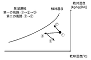
- Fig. 7 is a psychrometric diagram showing the state of air in the first and second air passages during dehumidification operation.
- the same numbers as in FIG. 2 are used when the state of the air undergoes the same process as in the first embodiment.
- the desiccant rotor 14 adsorbs moisture contained in the air.
- the air is dehumidified and changes from state 2 to state 3 in FIG. After that, the air is blown into the room from the first blowout port 21 .
- the air condition changes as follows. Room air in state 1 in FIG. In the desiccant rotor 14, the moisture adsorbed in the first air passage is desorbed.
- the humidity of the air passing through the desiccant rotor 14 increases, and the temperature of the air decreases due to heat of desorption. Therefore, the air changes from state 1 to state 7 as shown in FIG.
- the air that has passed through the desiccant rotor 14 is discharged outside through the second outlet 20a.
- the ventilation device 100a performs the dehumidifying operation. Next, the humidifying operation of the ventilator 100a will be described.
- the high-temperature, high-pressure heat medium discharged from the compressor 2 flows into the four-way valve 3 and the first heat exchanger 11 .
- the heat medium that has flowed out of the first heat exchanger 11 flows into the second expansion means 12b and is decompressed to become a low-temperature, low-pressure heat medium.
- the heat medium flows to the third heat exchanger 11b and is sucked into the compressor 2 again via the four-way valve 3 thereafter.
- first air blowing means 13, the second air blowing means 13a, and the third air blowing means 13b start operating. Thereby, air flows through the first air passage, the second air passage, and the third heat exchanger 11b.
- the desiccant rotor 14 does not rotate during the heating operation of the ventilator 100a. Therefore, the desiccant rotor 14 does not adsorb or desorb moisture. As will be described later, in the humidification operation of the ventilator 100a, the air is humidified by the humidifier 15. FIG.
- the air flowing out of the first heat exchanger 11 passes through the non-operating desiccant rotor 14 and flows into the humidifier 15 . This humidifies the air. At this time, the temperature of the air changes depending on the temperature of the moisture supplied from the humidifier 15, and if the temperature of the moisture is lower than the temperature of the air, the temperature drops. In this case, the air changes from state 4 to state 8 as shown in FIG.
- the ventilation device 100a in the present embodiment can perform dehumidification operation and humidification operation.
- the ventilator 100a has the following effects.
- the second heat exchanger 11a is not arranged in the housing 10a of the ventilation device 100a. Therefore, the size of the housing 10a can be reduced, making it easier to install the ventilator 100a.
- the first expansion means 12 is not arranged in the housing 10a. Therefore, the possibility that noise is generated by the first inflation means 12 and the user feels uncomfortable is reduced.
- Embodiment 3 of the present disclosure will be described with reference to FIGS. 9 to 11.
- FIG. The configuration of the ventilator 100b of the present embodiment is substantially the same as the configuration of the ventilator 100 of the first embodiment, but is partially different in configuration and function.
- the ventilator 100b according to the present embodiment will be described below, focusing on differences from the first embodiment.
- the parts whose description is omitted are the same as those in the first embodiment.
- FIG. 9 is a diagram showing the configuration of a ventilator 100b according to this embodiment. Compared with FIG. 1 of Embodiment 1, FIG. 9 differs in that a fourth heat exchanger 11c, a third expansion means 12b, and a humidifier 15 are arranged in a housing 10b. Moreover, the desiccant rotor 14 is not arranged in the housing 10b.
- the configuration of the outdoor unit 1 is the same as that of the first embodiment.
- the fourth heat exchanger 11c is a fin-tube heat exchanger similar to the first heat exchanger 11, for example.
- the shape of the fourth heat exchanger 11c that is, the number of paths, the path configuration, the shape of the fins, etc., may be the same as or different from that of the first heat exchanger 11.
- FIG. 9 the fourth heat exchanger 11c is located downstream of the first heat exchanger 11 in the first air passage.
- the third expansion means 12b is, for example, an electromagnetic valve capable of controlling the degree of opening similar to that of the first expansion means 12.
- the third expansion means 12b is arranged on the refrigerant circuit between the first heat exchanger 11 and the fourth heat exchanger 11c.
- the third expansion means 12b is desirably arranged so as not to be positioned between the first heat exchanger 11 and the second heat exchanger 11a on the refrigerant circuit.
- the pressure in the second heat exchanger 11a and the pressure in the fourth heat exchanger 11c can be independently controlled, so the operating range of the ventilator 100b is because it spreads.
- the humidifying device 15 is any water supply type humidifying device described in the modified example of the first embodiment.
- the humidifier 15 operates and humidifies the air when the ventilator 100b performs the humidification operation.
- the high-temperature, high-pressure heat medium discharged from the compressor 2 passes through the four-way valve 3 and flows into the second heat exchanger 11a and the fourth heat exchanger 11c. Therefore, a high-temperature and high-pressure heat medium flows through the second heat exchanger 11a and the fourth heat exchanger 11c.
- the heat medium that has passed through the second heat exchanger 11a flows into the first expansion means 12, and the heat medium that has passed through the fourth heat exchanger 11c flows into the third expansion means 12b.
- the pressure of the heat medium is reduced to a low temperature and low pressure. After that, the heat medium joins on the refrigerant circuit and flows into the first heat exchanger 11 . As a result, the temperature of the first heat exchanger 11 is lowered, and cooling and dehumidification is performed in the first heat exchanger 11 as described later.
- the heat medium that has flowed out of the first heat exchanger 11 is sucked into the compressor 2 again via the four-way valve 3 .
- the first air blower 13 and the second air blower 13a start operating, and air flows through the first air passage and the second air passage.
- FIG. 10 is a psychrometric diagram showing the state of air in the first and second air passages during the dehumidification operation.
- FIG. 10 when the air changes in the same way as in the first embodiment, the same numbers as in FIG. 2 are used.
- the temperature of the air that has flowed into the first heat exchanger 11 first drops.
- the relative humidity increases, and when it reaches nearly 100%, condensation begins.
- the absolute humidity of the air decreases by the moisture amount. This dehumidifies the air.
- the air cooled and dehumidified in the first heat exchanger 11 as described above then flows into the fourth heat exchanger 11c.
- a high-temperature, high-pressure heat medium is flowing through the fourth heat exchanger 11c. Therefore, the temperature of the air that has flowed into the fourth heat exchanger 11c rises. Also, the relative humidity decreases as the temperature of the air rises. As a result, the air condition changes from 9 to 10 in FIG. The air conditioned in this way is blown out from the first outlet 21 .
- the air condition changes as follows. Room air in state 1 in FIG. 10 is sucked from the second suction port 20a and flows into the second heat exchanger 11a. Since the high-temperature, high-pressure heat medium flows through the second heat exchanger 11a, the temperature of the air flowing into the second heat exchanger 11a rises. As a result, the air changes from state 1 to state 4 as in the first embodiment. The air that has passed through the second heat exchanger 11a is discharged to the outside through the second outlet 21a.
- the ventilation device 100b performs the dehumidifying operation. Next, the humidifying operation of the ventilator 100b will be described.
- the heat medium discharged from the compressor 2 flows into the first heat exchanger 11 via the four-way valve 3.
- the heat medium that has flowed out of the first heat exchanger 11 is decompressed by the first expansion means 12 and becomes low temperature and low pressure, and flows into the second heat exchanger 11a.
- the heat medium that has flowed out of the second heat exchanger 11 a is sucked into the compressor 2 again via the four-way valve 3 .
- the third expansion means 12b is closed and the heat medium does not flow. Therefore, no heat medium flows through the fourth heat exchanger 11c located downstream of the third expansion means 12b.
- the first blower means 13 and the second blower means 13a start operating. As a result, air flows through the first air passage and the second air passage.
- the air that has passed through the first heat exchanger 11 passes through the fourth heat exchanger 11 c and flows into the humidifier 15 .
- the air is humidified by the humidifier 15, and the state of the air changes from 4 to 8 as shown in FIG.
- the air thus conditioned is blown into the room from the first outlet 21 .
- the air sucked from the second suction port 20a flows into the low-temperature second heat exchanger 11a. This causes the temperature of the air to drop, and when the relative humidity increases, the humidity also drops due to condensation.
- the air that has flowed out of the second heat exchanger 11a is discharged outside through the second outlet 21a.
- the ventilation device 100b in the present embodiment can perform dehumidification operation and humidification operation.
- the ventilator 100b has the following effects.
- the ventilation device 100b is capable of dehumidifying operation and humidifying operation without disposing the desiccant rotor 14 inside the housing 10b. This eliminates the need for maintenance of the desiccant rotor 14, and reduces the cost and effort required to maintain the ventilator 100b.
- the desiccant rotor 14 having a large volume is not arranged in the housing 10b, the volume of the housing 10b is reduced, making it easier to install the ventilator 100b.
- Embodiment 4 of the present disclosure will be described with reference to FIGS. 12 to 14.
- FIG. The configuration of the ventilator 100c of the present embodiment is substantially the same as the configuration of the ventilator 100a of the second embodiment, but is partially different in configuration and function.
- the ventilator 100c according to the present embodiment will be described below, focusing on differences from the second embodiment.
- the parts whose explanation is omitted are the same as those in the second embodiment.
- FIG. 12 is a diagram showing the configuration of a ventilation device 100c according to this embodiment. Compared with FIG. 6 of Embodiment 2, FIG. 12 differs in that a fifth heat exchanger 11d, a sixth heat exchanger 11e, and a fourth blower 13c are arranged in the housing 10c. Furthermore, the point that the housing
- the fifth heat exchanger 11d and the sixth heat exchanger 11e are fin-tube heat exchangers similar to the first heat exchanger 11, for example.
- the shapes of the fifth heat exchanger 11d and the sixth heat exchanger 11e, that is, the number of paths, the path configuration, the shape of the fins, etc., may be the same as or different from the first heat exchanger 11.
- the housing 10c is provided with a third suction port 20b and a third outlet 21b.
- the third suction port 20b may have the same shape and position as the second outlet 21a, and the third outlet 21b may have the same shape and position as the second suction port 20a.
- the directions of air flow are different here, so for the sake of convenience, they will be described separately.
- the air passage the air passage connecting the third suction port 20b and the third air outlet 21b is referred to as the third air passage.
- the fifth heat exchanger 11d is located downstream of the desiccant rotor 14 in the first air passage. Furthermore, the sixth heat exchanger 11e is positioned upstream of the desiccant rotor 14 in the third air passage.
- the fourth air blowing means 13c sucks the outdoor air from the third suction port 20b and flows it to the sixth heat exchanger 11e and the desiccant rotor 14.
- the outdoor air is heat-exchanged by the sixth heat exchanger 11e, then humidified by the desiccant rotor 14, and blown into the room from the third outlet 21b. Therefore, in the ventilator 100c, ventilation is performed by second-class ventilation in which outdoor air is taken into the room from the third suction port 20b.
- Any means such as a sirocco fan, a propeller fan, or a cross flow fan can be used as the fourth air blowing means 13c.
- the high-temperature, high-pressure heat medium discharged from the compressor 2 flows through the four-way valve 3, the third heat exchanger 11b, and the second expansion means 12a.
- the heat medium is depressurized by the second expansion means 12a, becomes low temperature and low pressure, and flows into the sixth heat exchanger 11e.
- the heat medium then flows into the fifth heat exchanger 11 d and is finally sucked into the compressor 2 via the four-way valve 3 .
- the refrigerant circuit operates as described above, and the first air blowing means 13, the third air blowing means 13b, and the fourth air blowing means 13c operate.
- the first blower 13 blows air into the first air passage
- the third blower 13b blows air into the third heat exchanger 11b
- the fourth blower 13c blows air into the third air passage.
- the desiccant rotor 14 is rotated by a rotating device (not shown).
- FIG. 13 is a psychrometric diagram showing the state of air in the first and third air passages during dehumidification operation.
- the temperature of the air drops, and when the relative humidity rises to nearly 100%, the absolute humidity drops due to dew condensation. As a result, the air changes to state 12 in FIG.
- the air that has been conditioned as described above is blown into the room from the first outlet 21 .
- the air condition changes as follows. Outdoor air is first sucked from the third suction port 20b. When the dehumidifying operation is performed, the outdoor air is at high temperature and high humidity as indicated by 13 in FIG.
- the outdoor air sucked from the third suction port 20b flows into the sixth heat exchanger 11e, which has a lower temperature.
- the air is cooled, the temperature drops, and when the relative humidity approaches 100%, the absolute humidity drops due to condensation. As a result, the outdoor air is in the state indicated by 14 .
- the air flowing out of the sixth heat exchanger 11e flows into the desiccant rotor 14.
- the desiccant rotor 14 adsorbs moisture contained in the air. This lowers the absolute humidity of the air and increases the temperature of the air due to the heat of adsorption. As a result, the air is adjusted to the state of 15 in FIG. 14 and is blown into the room from the third outlet 21b.
- the ventilation device 100c performs the dehumidifying operation.
- the dehumidifying operation mixed air of the air blown out from the first blowout port 21 and the air blown out from the third blowout port 21b is blown into the room.
- the state of the air blown into the room is indicated by the points obtained by dividing the line segment connecting 12 and 15 in FIG. be For example, when the ratio of the amount of air blown out from the first outlet 21 and the third outlet 21b is 7:3, the state of the mixed air is the line connecting 12 and 15 in FIG. It is indicated by dividing the minute by ten and moving from 12 to the 15 side by 3 minutes.
- the high-temperature, high-pressure heat medium discharged from the compressor 2 passes through the four-way valve 3, the fifth heat exchanger 11d, the sixth heat exchanger 11e, and the second expansion means 12a in that order. flow.
- the heat medium depressurized by the second expansion means 12 a and reduced to a low temperature and low pressure flows into the third heat exchanger 11 b and is then sucked into the compressor 2 via the four-way valve 3 .
- the first air blowing means 13, the third air blowing means 13b, and the fourth air blowing means 13c operate, respectively, the first air passage, the third heat exchanger 11b, and the third heat exchanger 11b. to flow air through the air passages of During the humidification operation, the desiccant rotor 14 does not operate, and humidification is performed by the humidifier 15 .
- a high-temperature heat medium flows through the fifth heat exchanger 11d. Therefore, the temperature of the air flowing into the fifth heat exchanger 11d rises and changes to the state of 4.
- FIG. 1 A high-temperature heat medium flows through the fifth heat exchanger 11d. Therefore, the temperature of the air flowing into the fifth heat exchanger 11d rises and changes to the state of 4.
- the air that flows out from the fifth heat exchanger 11d is humidified by the humidifier 15. As a result, the air changes to state 8 in FIG. The air conditioned in this way is blown into the room from the first outlet 21 .
- the air changes as follows.
- the outdoor air sucked from the third suction port 20b is low temperature air as indicated by 16 in FIG.
- the low-temperature outdoor air flows into the high-temperature sixth heat exchanger 11e and is heated.
- the temperature of the air rises to the state shown by 17 in FIG.
- the air that has flowed out of the sixth heat exchanger 11e passes through the non-operating desiccant rotor 14 and is blown into the room from the third blowout port 21b.
- the ventilation device 100c performs the humidification operation.
- the state of the air blown into the room in the humidifying operation is defined by the line segment connecting 8 and 17 in FIG. , divided by the inverse ratio of the amount of air blown out from
- the state of the mixed air is the line connecting 8 and 17 in FIG. It is indicated by dividing a minute by ten and moving from 8 to the 17 side by 4 minutes.
- the ventilation device 100c in the present embodiment can perform dehumidification operation and humidification operation.
- the ventilator 100c has the following effects.
- the ventilation device 100c is a second-class ventilation device that ventilates the room by supplying air. Therefore, the pressure in the room can be kept positive, and dust can be prevented from entering from the outside due to the opening and closing of the doorway.
- the ventilation device of the present disclosure is particularly suitable for installation in spaces that require ventilation.
- Reference Signs List 1 1a outdoor unit 2 compressor 3 four-way valves 10, 10a, 10b, 10c housing 11, 11a, 11b, 11c, 11d, 11e Heat exchangers 12, 12a, 12b Expansion means 13, 13a, 13b, 13c Blower means 14 Desiccant rotor 15 Humidifier 20, 20a, 20b Suction ports 21, 21a, 21b Blow out mouth 100, 100a, 100b, 100c ventilator 1000 wall
Landscapes
- Chemical & Material Sciences (AREA)
- Engineering & Computer Science (AREA)
- Combustion & Propulsion (AREA)
- Mechanical Engineering (AREA)
- General Engineering & Computer Science (AREA)
- Analytical Chemistry (AREA)
- General Chemical & Material Sciences (AREA)
- Oil, Petroleum & Natural Gas (AREA)
- Chemical Kinetics & Catalysis (AREA)
- Dispersion Chemistry (AREA)
- Central Air Conditioning (AREA)
Priority Applications (3)
| Application Number | Priority Date | Filing Date | Title |
|---|---|---|---|
| PCT/JP2021/016205 WO2022224384A1 (ja) | 2021-04-21 | 2021-04-21 | 換気装置 |
| JP2023515956A JPWO2022224384A1 (https=) | 2021-04-21 | 2021-04-21 | |
| US18/546,191 US20240117978A1 (en) | 2021-04-21 | 2021-04-21 | Ventilator |
Applications Claiming Priority (1)
| Application Number | Priority Date | Filing Date | Title |
|---|---|---|---|
| PCT/JP2021/016205 WO2022224384A1 (ja) | 2021-04-21 | 2021-04-21 | 換気装置 |
Publications (1)
| Publication Number | Publication Date |
|---|---|
| WO2022224384A1 true WO2022224384A1 (ja) | 2022-10-27 |
Family
ID=83722150
Family Applications (1)
| Application Number | Title | Priority Date | Filing Date |
|---|---|---|---|
| PCT/JP2021/016205 Ceased WO2022224384A1 (ja) | 2021-04-21 | 2021-04-21 | 換気装置 |
Country Status (3)
| Country | Link |
|---|---|
| US (1) | US20240117978A1 (https=) |
| JP (1) | JPWO2022224384A1 (https=) |
| WO (1) | WO2022224384A1 (https=) |
Cited By (1)
| Publication number | Priority date | Publication date | Assignee | Title |
|---|---|---|---|---|
| WO2025100145A1 (ja) * | 2023-11-09 | 2025-05-15 | 株式会社西部技研 | ガス吸着装置 |
Families Citing this family (1)
| Publication number | Priority date | Publication date | Assignee | Title |
|---|---|---|---|---|
| WO2025264987A1 (en) * | 2024-06-20 | 2025-12-26 | Transaera, Inc. | Systems and methods related to heat pumps with adsorbent |
Citations (8)
| Publication number | Priority date | Publication date | Assignee | Title |
|---|---|---|---|---|
| JPH1194316A (ja) * | 1997-09-24 | 1999-04-09 | Sharp Corp | 除・加湿装置 |
| JPH11304194A (ja) * | 1998-04-22 | 1999-11-05 | Takasago Thermal Eng Co Ltd | デシカント空調方法 |
| JP2000346396A (ja) * | 1999-06-10 | 2000-12-15 | Ebara Corp | 除湿方法及び除湿装置 |
| JP2002081688A (ja) * | 2000-09-05 | 2002-03-22 | Matsushita Electric Ind Co Ltd | 換気装置 |
| JP2006010307A (ja) * | 2004-05-26 | 2006-01-12 | Mitsubishi Chemicals Corp | 加湿装置および加湿方法 |
| JP2007327712A (ja) * | 2006-06-09 | 2007-12-20 | Japan Exlan Co Ltd | 湿度調節装置 |
| JP2011017522A (ja) * | 2009-06-08 | 2011-01-27 | Chofu Seisakusho Co Ltd | 床置型熱交換式換気扇 |
| JP2018146217A (ja) * | 2017-03-09 | 2018-09-20 | ダイキン工業株式会社 | 調湿装置 |
Family Cites Families (7)
| Publication number | Priority date | Publication date | Assignee | Title |
|---|---|---|---|---|
| IL64915A (en) * | 1982-02-02 | 1985-04-30 | Joel Harband | Apparatus and method for temperature and humidity control |
| JP2003130391A (ja) * | 2001-10-18 | 2003-05-08 | Sanyo Electric Co Ltd | 空気調和機 |
| JP2006071168A (ja) * | 2004-09-01 | 2006-03-16 | Sanden Corp | 空気調和装置 |
| JP4169747B2 (ja) * | 2005-03-09 | 2008-10-22 | 三洋電機株式会社 | 空気調和機 |
| WO2014174623A1 (ja) * | 2013-04-24 | 2014-10-30 | 三菱電機株式会社 | 除湿装置 |
| JP6116096B2 (ja) * | 2013-09-24 | 2017-04-19 | 株式会社日立製作所 | 除湿システム |
| JP2020012602A (ja) * | 2018-07-19 | 2020-01-23 | 株式会社西部技研 | 外気調和機 |
-
2021
- 2021-04-21 WO PCT/JP2021/016205 patent/WO2022224384A1/ja not_active Ceased
- 2021-04-21 JP JP2023515956A patent/JPWO2022224384A1/ja active Pending
- 2021-04-21 US US18/546,191 patent/US20240117978A1/en active Pending
Patent Citations (8)
| Publication number | Priority date | Publication date | Assignee | Title |
|---|---|---|---|---|
| JPH1194316A (ja) * | 1997-09-24 | 1999-04-09 | Sharp Corp | 除・加湿装置 |
| JPH11304194A (ja) * | 1998-04-22 | 1999-11-05 | Takasago Thermal Eng Co Ltd | デシカント空調方法 |
| JP2000346396A (ja) * | 1999-06-10 | 2000-12-15 | Ebara Corp | 除湿方法及び除湿装置 |
| JP2002081688A (ja) * | 2000-09-05 | 2002-03-22 | Matsushita Electric Ind Co Ltd | 換気装置 |
| JP2006010307A (ja) * | 2004-05-26 | 2006-01-12 | Mitsubishi Chemicals Corp | 加湿装置および加湿方法 |
| JP2007327712A (ja) * | 2006-06-09 | 2007-12-20 | Japan Exlan Co Ltd | 湿度調節装置 |
| JP2011017522A (ja) * | 2009-06-08 | 2011-01-27 | Chofu Seisakusho Co Ltd | 床置型熱交換式換気扇 |
| JP2018146217A (ja) * | 2017-03-09 | 2018-09-20 | ダイキン工業株式会社 | 調湿装置 |
Cited By (1)
| Publication number | Priority date | Publication date | Assignee | Title |
|---|---|---|---|---|
| WO2025100145A1 (ja) * | 2023-11-09 | 2025-05-15 | 株式会社西部技研 | ガス吸着装置 |
Also Published As
| Publication number | Publication date |
|---|---|
| US20240117978A1 (en) | 2024-04-11 |
| JPWO2022224384A1 (https=) | 2022-10-27 |
Similar Documents
| Publication | Publication Date | Title |
|---|---|---|
| JP4835688B2 (ja) | 空気調和装置、空調システム | |
| KR101746154B1 (ko) | 공기조화 시스템 | |
| US7730736B2 (en) | Air conditioning system | |
| AU2004295536B2 (en) | Air conditioning system | |
| CN107923642B (zh) | 空调系统 | |
| CN103221752B (zh) | 空气调节系统和调湿装置 | |
| JP5183236B2 (ja) | 置換空調システム | |
| JP2000220877A (ja) | 換気空調機 | |
| CN113654127A (zh) | 空调器及其控制方法 | |
| KR20200092221A (ko) | 공조 시스템 | |
| CN215446665U (zh) | 空调器 | |
| WO2022224384A1 (ja) | 換気装置 | |
| JP5594030B2 (ja) | コントローラ、調湿用制御部および空調処理システム | |
| JPH0228774B2 (https=) | ||
| CN1273783C (zh) | 多室型空调机 | |
| CN112923459A (zh) | 新风系统 | |
| JP4333986B2 (ja) | 空気調和機 | |
| WO2007123144A1 (ja) | 換気システム | |
| CN207849566U (zh) | 一种带独立新风除湿的多联式空调系统 | |
| EP3640554B1 (en) | Humidity control unit | |
| KR102522682B1 (ko) | 열회수 환기장치에 부가되는 공조기를 구비한 공조 시스템 | |
| JPH09287848A (ja) | 熱交換型換気装置 | |
| JP2025126975A (ja) | 外気処理空気調和機 | |
| WO2023276588A1 (ja) | 空気調和システム | |
| WO2023145162A1 (ja) | 換気装置 |
Legal Events
| Date | Code | Title | Description |
|---|---|---|---|
| 121 | Ep: the epo has been informed by wipo that ep was designated in this application |
Ref document number: 21937878 Country of ref document: EP Kind code of ref document: A1 |
|
| ENP | Entry into the national phase |
Ref document number: 2023515956 Country of ref document: JP Kind code of ref document: A |
|
| WWE | Wipo information: entry into national phase |
Ref document number: 18546191 Country of ref document: US |
|
| NENP | Non-entry into the national phase |
Ref country code: DE |
|
| 122 | Ep: pct application non-entry in european phase |
Ref document number: 21937878 Country of ref document: EP Kind code of ref document: A1 |