WO2022220068A1 - 電子機器 - Google Patents
電子機器 Download PDFInfo
- Publication number
- WO2022220068A1 WO2022220068A1 PCT/JP2022/014375 JP2022014375W WO2022220068A1 WO 2022220068 A1 WO2022220068 A1 WO 2022220068A1 JP 2022014375 W JP2022014375 W JP 2022014375W WO 2022220068 A1 WO2022220068 A1 WO 2022220068A1
- Authority
- WO
- WIPO (PCT)
- Prior art keywords
- housing
- recess
- pair
- side surfaces
- electronic device
- Prior art date
- Legal status (The legal status is an assumption and is not a legal conclusion. Google has not performed a legal analysis and makes no representation as to the accuracy of the status listed.)
- Ceased
Links
Images


Classifications
-
- G—PHYSICS
- G06—COMPUTING OR CALCULATING; COUNTING
- G06F—ELECTRIC DIGITAL DATA PROCESSING
- G06F1/00—Details not covered by groups G06F3/00 - G06F13/00 and G06F21/00
- G06F1/16—Constructional details or arrangements
- G06F1/1613—Constructional details or arrangements for portable computers
- G06F1/1615—Constructional details or arrangements for portable computers with several enclosures having relative motions, each enclosure supporting at least one I/O or computing function
- G06F1/1616—Constructional details or arrangements for portable computers with several enclosures having relative motions, each enclosure supporting at least one I/O or computing function with folding flat displays, e.g. laptop computers or notebooks having a clamshell configuration, with body parts pivoting to an open position around an axis parallel to the plane they define in closed position
-
- G—PHYSICS
- G06—COMPUTING OR CALCULATING; COUNTING
- G06F—ELECTRIC DIGITAL DATA PROCESSING
- G06F1/00—Details not covered by groups G06F3/00 - G06F13/00 and G06F21/00
- G06F1/16—Constructional details or arrangements
- G06F1/1613—Constructional details or arrangements for portable computers
- G06F1/1633—Constructional details or arrangements of portable computers not specific to the type of enclosures covered by groups G06F1/1615 - G06F1/1626
- G06F1/1684—Constructional details or arrangements related to integrated I/O peripherals not covered by groups G06F1/1635 - G06F1/1675
- G06F1/1688—Constructional details or arrangements related to integrated I/O peripherals not covered by groups G06F1/1635 - G06F1/1675 the I/O peripheral being integrated loudspeakers
-
- G—PHYSICS
- G06—COMPUTING OR CALCULATING; COUNTING
- G06F—ELECTRIC DIGITAL DATA PROCESSING
- G06F1/00—Details not covered by groups G06F3/00 - G06F13/00 and G06F21/00
- G06F1/16—Constructional details or arrangements
- G06F1/1613—Constructional details or arrangements for portable computers
- G06F1/1633—Constructional details or arrangements of portable computers not specific to the type of enclosures covered by groups G06F1/1615 - G06F1/1626
- G06F1/1684—Constructional details or arrangements related to integrated I/O peripherals not covered by groups G06F1/1635 - G06F1/1675
- G06F1/169—Constructional details or arrangements related to integrated I/O peripherals not covered by groups G06F1/1635 - G06F1/1675 the I/O peripheral being an integrated pointing device, e.g. trackball in the palm rest area, mini-joystick integrated between keyboard keys, touch pads or touch stripes
-
- G—PHYSICS
- G06—COMPUTING OR CALCULATING; COUNTING
- G06F—ELECTRIC DIGITAL DATA PROCESSING
- G06F3/00—Input arrangements for transferring data to be processed into a form capable of being handled by the computer; Output arrangements for transferring data from processing unit to output unit, e.g. interface arrangements
- G06F3/01—Input arrangements or combined input and output arrangements for interaction between user and computer
- G06F3/03—Arrangements for converting the position or the displacement of a member into a coded form
- G06F3/033—Pointing devices displaced or positioned by the user, e.g. mice, trackballs, pens or joysticks; Accessories therefor
- G06F3/0354—Pointing devices displaced or positioned by the user, e.g. mice, trackballs, pens or joysticks; Accessories therefor with detection of two-dimensional [2D] relative movements between the device, or an operating part thereof, and a plane or surface, e.g. 2D mice, trackballs, pens or pucks
- G06F3/03547—Touch pads, in which fingers can move on a surface
-
- H—ELECTRICITY
- H05—ELECTRIC TECHNIQUES NOT OTHERWISE PROVIDED FOR
- H05K—PRINTED CIRCUITS; CASINGS OR CONSTRUCTIONAL DETAILS OF ELECTRIC APPARATUS; MANUFACTURE OF ASSEMBLAGES OF ELECTRICAL COMPONENTS
- H05K5/00—Casings, cabinets or drawers for electric apparatus
- H05K5/02—Details
Definitions
- the present disclosure relates to an electronic device including a speaker unit.
- Patent Literature 1 discloses an electronic device having a convex portion formed to protrude outward from the bottom surface of the housing.
- the electronic device disclosed in Patent Literature 1 includes a speaker section provided within a projection, and an opening formed in an inclined surface of the projection for transmitting sound emitted by the speaker section to the outside.
- An object of the present disclosure is to provide an electronic device capable of suppressing a decrease in sound pressure of sound emitted by a speaker unit.
- An electronic device includes: a first housing having a first outer surface on which a keyboard is arranged and a second outer surface facing away from the first outer surface; a second housing that houses a display unit and is connected to the first housing; a speaker unit arranged inside the first housing, a recess is formed in the second outer surface; A through hole is formed in at least a part of the surface of the recess, At least a portion of the speaker unit faces at least a portion of the back surface of the concave portion in which the through hole is formed.
- an electronic device capable of suppressing a decrease in sound pressure of sound emitted by a speaker unit.
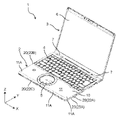
- FIG. 1 is a perspective view of an example of an electronic device according to Embodiment 1 of the present disclosure
- FIG. 2 is a bottom view of the first housing of the electronic device of FIG. 1
- FIG. 2 is a right side view of the first housing of the electronic device of FIG. 1
- FIG. 4 is a cross-sectional view of the first housing of the electronic device of FIG. 3 taken along line IV-IV
- FIG. 3 is an enlarged view of a portion V of FIG. 2
- 4 is an enlarged view of the VI portion of FIG. 3
- FIG. FIG. 5 is an enlarged view of the VII portion of FIG. 4
- FIG. 3 is a diagram showing the internal space of the first housing of the electronic device of FIG. 2 with a part of the first housing removed;
- FIG. 3 is a diagram showing the internal space of the first housing of the electronic device of FIG. 2 with a part of the first housing removed;
- FIG. 3 is a diagram showing the internal space of the first housing of the electronic device of FIG. 2 with
- FIG. 10 is a schematic bottom view of the first housing showing a modified example of the recess and its periphery in the first embodiment according to the present disclosure
- FIG. 5 is a schematic right side view of the first housing showing a modified example of the recess and its periphery in Embodiment 1 according to the present disclosure
- Electronic devices include, for example, notebook computers (laptop PCs).
- a notebook computer includes a first housing that houses a keyboard and a second housing that houses a display unit.
- the first housing and the second housing are rotatably connected via a hinge.
- the speaker unit is built in the first housing, and a through hole is formed in the first housing for transmitting the sound emitted by the speaker unit to the outside of the computer.
- remote work is when employees work from a location other than the office where they work. With the spread of remote work, there are more opportunities for meetings to be held by multiple people in different places. In this case, it is required to improve the sound pressure of the sound emitted from each person's computer.
- the through-hole is formed on the hinge side of the surface of the first housing. This is because if the through hole is formed on the surface of the first housing on the side opposite to the hinge, the user's hand or arm operating the keyboard may block the through hole.
- a concave portion is formed in the back surface of the first housing, and a through hole is formed in the concave portion for transmitting the sound emitted by the speaker unit to the outside, resulting in the following invention. rice field.
- the electronic device of the first aspect of the present disclosure includes a first housing having a first outer surface on which a keyboard is arranged and a second outer surface facing away from the first outer surface; a second housing that houses a display unit and is connected to the first housing; a speaker unit arranged inside the first housing, a recess is formed in the second outer surface; A through hole is formed in at least a part of the surface of the recess, At least a portion of the speaker unit faces at least a portion of the back surface of the concave portion in which the through hole is formed.
- the first housing may have a third outer surface located between the peripheral edge of the first outer surface and the peripheral edge of the second outer surface, The recess may open to the third outer surface.
- the recess is opened to the third outer surface in addition to the second outer surface. Therefore, the sound emitted by the speaker unit can be transmitted to the outside of the electronic device through the opening in the third outer surface.
- the recess may have a bottom surface continuous with the third outer surface, The bottom surface may be inclined toward the third outer surface in a direction approaching the first outer surface.
- the distance between the bottom surface of the recess and the second outer surface increases toward the third outer surface. Therefore, the sound of the speaker unit that is transmitted to the outside of the electronic device through the opening in the third outer surface can be spread in the concave portion. Therefore, the sound pressure and quality of the sound emitted by the speaker unit can be improved.
- An inclination angle of the bottom surface with respect to the second outer surface may be 1° or more and 45° or less.
- the recess may have a pair of side surfaces facing each other and each continuous with the third outer surface, At least one of the pair of side surfaces may be inclined toward the third outer surface in a direction to increase the distance between the pair of side surfaces.
- the distance between the pair of side surfaces becomes wider toward the third outer surface. Therefore, the sound of the speaker unit that is transmitted to the outside of the electronic device through the opening in the third outer surface can be spread in the concave portion. Therefore, the sound pressure and quality of the sound emitted by the speaker unit can be improved.
- the recess may have a pair of side surfaces facing each other and each continuous with the second outer surface, At least one of the pair of side surfaces may be inclined toward the second outer surface in a direction to increase the distance between the pair of side surfaces.
- the distance between the pair of side surfaces becomes wider toward the second outer surface. Therefore, the sound of the speaker unit that is transmitted to the outside of the electronic device through the opening in the second outer surface can be spread in the concave portion. Therefore, the sound pressure and quality of the sound emitted by the speaker unit can be improved.
- the recess may have a pair of side surfaces facing each other and each continuous with the second outer surface and the third outer surface, The pair of side surfaces are inclined toward the second outer surface in a direction of increasing the distance between the pair of side surfaces, and are inclined toward the third outer surface in a direction of increasing the distance between the pair of side surfaces.
- the distance between the pair of side surfaces widens toward the second outer surface and widens toward the third outer surface. Accordingly, the sound of the speaker unit that is transmitted to the outside of the electronic device through the opening in the second outer surface and the opening in the third outer surface can be spread in the concave portion. Therefore, the sound pressure and quality of the sound emitted by the speaker unit can be improved.
- the angle of inclination of each of the pair of side surfaces that are inclined toward the third outer surface in a direction that increases the distance between the pair of side surfaces with respect to a virtual plane orthogonal to the second and third outer surfaces is 5° or more. It may be 45° or less.
- the sound spread can be increased by setting the inclination angle to 5° or more. Moreover, in this configuration, the inclination angle is set to 45° or less. As a result, sound pressure reduction can be suppressed by utilizing the echo of sound between the pair of side surfaces.
- the angle of inclination of each of the pair of side surfaces that are inclined toward the second outer surface in a direction that increases the distance between the pair of side surfaces with respect to a virtual plane orthogonal to the second outer surface and the third outer surface is 5° or more. It may be 45° or less.
- the sound spread can be increased by setting the inclination angle to 5° or more. Moreover, in this configuration, the inclination angle is set to 45° or less. As a result, sound pressure reduction can be suppressed by utilizing the echo of sound between the pair of side surfaces.
- the third outer surface is a right outer surface located outside one longitudinal end of the keyboard; a left outer surface located outside the other end in the longitudinal direction of the keyboard and facing opposite to the right outer surface;
- the recess is a first recess opening on the right outer surface;
- a second recess opening on the left outer surface may be provided,
- the speaker unit is a first speaker unit facing at least a portion of the back surface of the surface of the first recess in which the through hole is formed; and a second speaker unit facing at least a portion of the back surface of the surface of the second recess in which the through hole is formed.
- the sound pressure and sound quality of the sound emitted by the speaker unit can be maintained well in 360-degree directions around the electronic device when the first housing is viewed from a direction perpendicular to the second outer surface. .
- An electronic device includes: A speaker box may be arranged inside the first housing and to which the speaker unit is mounted.
- FIG. 1 is a perspective view of an example of an electronic device 1 according to Embodiment 1 of the present disclosure.
- FIG. 2 is a bottom view of the housing 2 of the electronic device of FIG.
- the X, Y, and Z directions in the drawing indicate the width direction, depth direction, and height direction of the housing 2, respectively.
- the electronic device 1 is a notebook personal computer (laptop PC).
- Electronic device 1 includes housing 2 and housing 3 .
- the housing 2 is an example of a first housing.
- the housing 3 is an example of a second housing.
- Each of the housings 2 and 3 has a thin box-shaped outer shell, and has a rectangular shape when viewed from the top side.
- the housing 2 houses the keyboard 4 and the touchpad 5.
- the housing 3 accommodates the liquid crystal panel 6 .
- the liquid crystal panel 6 is an example of a display section.
- the keyboard 4 and the touch pad 5 are sometimes referred to as the input units 4 and 5
- the liquid crystal panel 6 is sometimes referred to as the display unit 6.
- the housings 2 and 3 are connected via the hinge portion 7.
- the hinge part 7 is provided at the end of the housing 2 in the depth direction (Y direction).
- the hinge portion 7 rotatably connects the housings 2 and 3 .
- At least one of the housings 2 and 3 can be rotated by the hinge portion 7 to open and close the electronic device 1 .
- the electronic device 1 can be placed in an open state and a closed state by the hinge portion 7 .
- the “open state” means a state in which the housings 2 and 3 are separated from each other and the input sections 4 and 5 and the display section 6 are exposed.
- the “closed state” means that the housings 2 and 3 are arranged facing each other, the input sections 4 and 5 and the display section 6 face each other, and the input sections 4 and 5 and the display section 6 are not exposed. means state.
- the housing 2 includes cases 10 and 20. Cases 10 and 20 are fitted together. Cases 10 and 20 are made of a metal material. Examples of metal materials include materials such as magnesium alloys.
- the case 10 faces the housing 3 when the electronic device 1 is in the closed state.
- the case 20 is located on the opposite side of the housing 3 with respect to the case 10 when the electronic device 1 is in the closed state. Cases 10 and 20 are fixed to each other by a plurality of screws at the outer peripheral portion of housing 2 .
- the space between the cases 10 and 20 is the internal space of the housing 2.
- a keyboard 4 and a touch pad 5 are accommodated in this internal space.
- the case 10 has an outer surface 11.
- the outer surface 11 is an example of a first outer surface.
- the outer surface 11 faces the liquid crystal panel 6 of the housing 3 when the electronic device 1 is in the closed state.
- the keyboard 4 is exposed to the outside of the housing 2 through the larger one of the two openings.
- the touch pad 5 is exposed to the outside of the housing 2 through the smaller opening of the two openings. That is, the keyboard 4 and the touchpad 5 are arranged on the outer surface 11 .
- the case 20 has outer surfaces 21 and 22.
- the outer surface 21 is an example of a second outer surface.
- the outer surface 22 is an example of a third outer surface.
- the outer surface 21 faces away from the outer surface 11 of the case 10 .
- the outer surface 21 is located on the opposite side of the housing 3 with respect to the outer surface 11 of the case 10 when the electronic device 1 is in the closed state.
- the outer surface 22 protrudes from the peripheral edge portion 21A of the outer surface 21 toward the peripheral edge portion 11A of the outer surface 11 of the case 10 (Z direction).
- the peripheral edge portion 21A of the outer surface 21 refers to the sides of the outer surface 21 and the vicinity of the sides.
- the peripheral edge portion 11A of the outer surface 11 refers to the sides of the outer surface 11 and the vicinity of the sides.
- the outer surface 22 protrudes to a position where it contacts the peripheral edge portion 11A of the outer surface 11 of the case 10 or to the vicinity of the position. That is, the outer surface 22 is positioned between the peripheral edge portion 11A of the outer surface 11 and the peripheral edge portion 21A of the outer surface 21 .
- the outer surface 22 includes a right outer surface 22A, a left outer surface 22B, an anterior outer surface 22C, and a posterior outer surface 22D.
- the outer surface 22 on the right side is defined as the right outer surface 22A
- the outer surface 22 on the left side is the left outer surface. 22B.
- the right outer surface 22A protrudes in the height direction (Z direction) from one end in the width direction (X direction) of the outer surface 21 and extends along the depth direction (Y direction) of the outer surface 21 .
- the left outer surface 22B faces away from the right outer surface 22A.
- the left outer surface 22B protrudes in the height direction (Z direction) from the other end in the width direction (X direction) of the outer surface 21 and extends along the depth direction (Y direction) of the outer surface 21 .
- the front lateral surface 22C protrudes in the height direction (Z direction) from the end of the outer surface 21 opposite to the hinge portion 7 in the depth direction (Y direction) and extends along the width direction (X direction) of the outer surface 21. .
- the front lateral surface 22C connects the right lateral surface 22A and the left lateral surface 22B.
- the rear outer side surface 22D protrudes in the height direction (Z direction) from the edge of the outer surface 21 on the side of the hinge portion 7 in the depth direction (Y direction) and extends along the width direction (X direction) of the outer surface 21 .
- the rear lateral surface 22D connects the right lateral surface 22A and the left lateral surface 22B.
- the outer surface 22 is located outside the keyboard 4 when the housing 2 is viewed from the height direction (Z direction).
- the right outer surface 22A is located outside one end of the keyboard 4 in the longitudinal direction (X direction).
- the longitudinal direction of the keyboard 4 corresponds to the width direction (X direction) of the housing 2 .
- the left outer surface 22B is located outside the other longitudinal end of the keyboard 4 .
- the front outer side surface 22C is located outside the end of the keyboard 4 opposite to the hinge portion 7 in the short direction.
- the short direction of the keyboard 4 corresponds to the depth direction (Y direction) of the housing 2 .
- the rear outer side surface 22D is located outside the edge of the keyboard 4 on the side of the hinge part 7 in the short direction.
- a recess 23 is formed in the outer surface 21 of the housing 2 .
- recess 23 includes two recesses 23A and 23B.
- the recess 23A is an example of a first recess.
- the recess 23B is an example of a second recess.
- the depth of recesses 23A and 23B is set to 1 mm or more. Accordingly, when the electronic device 1 is used on the knee or the like, the concave portions 23A and 23B are prevented from being blocked by the knee or the like from below. Note that the depth of the concave portions 23A and 23B may be less than 1 mm.
- the recess 23 is formed in the peripheral edge portion 21A of the outer surface 21. As shown in FIG. As shown in FIG. 1 , the recess 23 is formed at the end opposite to the hinge portion 7 in the depth direction (Y direction) of the housing 2 . As shown in FIG. 2, the recess 23A is formed at one end of the housing 2 in the width direction (X direction). The recess 23B is formed at the other end of the housing 2 in the width direction (X direction). The position of the recess 23A in the width direction (X direction) is the same as the position of the recess 23B in the width direction (X direction).
- FIG. 3 is a right side view of the first housing of the electronic device of FIG.
- FIG. 4 is a cross-sectional view of the first housing of the electronic device of FIG. 3 taken along line IV-IV.
- the recesses 23A and 23B open downward (opposite to the Z direction) of the housing 2.
- the recesses 23A, 23B are open to the outer surface 21 . That is, the recesses 23A and 23B each have an opening 23a.
- the recesses 23A and 23B are opened in the width direction (X direction) of the housing 2.
- the recesses 23A, 23B are open to the outer surface 22.
- the recess 23A opens to the right outer surface 22A
- the recess 23B opens to the left outer surface 22B.
- the recesses 23A and 23B each have an opening 23b.
- the openings 23a and 23b are continuous.
- the configuration of the recess 23A will be described in further detail below.
- the concave portion 23B has the same configuration as the concave portion 23A except that it faces in the opposite direction to the concave portion 23A in the width direction (X direction) of the housing 2 . Therefore, detailed description of the configuration of the recess 23B is omitted.
- FIG. 5 is an enlarged view of the V portion of FIG. 6 is an enlarged view of the VI portion of FIG. 3.
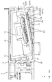
- FIG. 7 is an enlarged view of the VII portion of FIG. 4.
- the recess 23A has a bottom surface 231 and a pair of side surfaces 232 and 233 as surfaces forming the recess 23A.
- the bottom surface 231 and the pair of side surfaces 232 and 233 are examples of surfaces of the recess.
- the bottom surface 231 is continuous with the outer surface 21, the right outer surface 22A, and the pair of side surfaces 232,233.
- one end of the bottom surface 231 in the width direction (X direction) is continuous with the outer surface 21 .
- the other end in the width direction (X direction) of the bottom surface 231 of the recess 23A is continuous with the right outer surface 22A.
- the bottom surface 231 is sandwiched between a pair of side surfaces 232 and 233 on both sides of the housing 2 in the depth direction (Y direction).
- An end portion of the bottom surface 231 on the front outer side surface 22C side in the depth direction (Y direction) is continuous with the side surface 232 .
- the end of the bottom surface 231 opposite to the front lateral surface 22 ⁇ /b>C in the depth direction (Y direction) is continuous with the side surface 233 .
- the bottom surface 231 is inclined away from the outer surface 21 in the height direction (Z direction) of the housing 2 from one end in the width direction (X direction) of the bottom surface 231 toward the other end. do.
- the bottom surface 231 is inclined in a direction (Z direction) toward the outer surface 11 of the housing 3 toward the right outer surface 22A.
- the inclination angle ⁇ 1 of the bottom surface 231 with respect to the outer surface 21 is, for example, 10°.
- the inclination angle ⁇ 1 is 10° in Embodiment 1, it may not be 10°.
- the inclination angle ⁇ 1 may be any angle between 1° and 45°.
- the bottom surface 231 is formed with 28 through holes 23c.
- the 28 through-holes 23c are arranged in a lattice.
- the 28 through-holes 23c are formed in a region of the bottom surface 231 excluding the other end in the width direction (X direction). That is, 28 through-holes 23 c are formed in a partial area of the bottom surface 231 .
- the number of through-holes 23c is not limited to 28, and may be, for example, 1 or 40.
- the arrangement of the through-holes 23c is not limited to a grid-like row.
- the through holes 23c may be arranged in a line or may be arranged in a circle.
- the through hole 23c may be formed in at least part of the surface of the recess 23.
- the through holes 23c may be formed in the entire area of the bottom surface 231 .
- the pair of side surfaces 232, 233 of the recess 23A are respectively continuous with the bottom surface 231, the outer surface 21, and the right outer surface 22A.
- the pair of side surfaces 232 and 233 are sandwiched from both sides in the depth direction (Y direction) of the housing 2 by the bottom surface 231 and the outer surface 21, respectively.
- Width direction (X direction) ends of the pair of side surfaces 232, 233 of the recess 23A are respectively continuous with the right outer side surface 22A.
- the side surface 232 is inclined toward the right outer surface 22A along the width direction (X direction) of the side surface 232 and away from the side surface 233 in the depth direction (Y direction) of the housing 2.
- the side surface 233 is inclined along the width direction (X direction) of the side surface 233 toward the right outer surface 22A and away from the side surface 232 in the depth direction (Y direction) of the housing 2 .
- the pair of side surfaces 232 and 233 are inclined toward the right outer side surface 22A in the direction of increasing the distance between the pair of side surfaces 232 and 233.
- the side surface 232 is inclined away from the side surface 233 in the depth direction (Y direction) of the housing 2 as it separates from the bottom surface 231 in the height direction (Z direction) of the housing 2. do. Further, the side surface 233 is inclined away from the side surface 232 in the depth direction (Y direction) of the housing 2 as it separates from the bottom surface 231 in the height direction (Z direction) of the housing 2 . That is, the pair of side surfaces 232 and 233 are inclined toward the outer surface 21 in the direction of increasing the distance between the pair of side surfaces 232 and 233 .
- the angle of inclination ⁇ 2 of each of the pair of side surfaces 232 and 233 inclined toward the right outer surface 22A in the direction of increasing the distance between the pair of side surfaces 232 and 233 with respect to the virtual plane 25 is, for example, 10 °.
- the virtual plane 25 is a plane orthogonal to the outer surface 21 and the right outer surface 22A.
- the inclination angle ⁇ 2 is 10° in the first embodiment, it does not have to be 10°.
- the inclination angle ⁇ 2 may be any angle between 5° and 45°.
- the angle of inclination ⁇ 3 of each of the pair of side surfaces 232 and 233 inclined toward the outer surface 21 in the direction of increasing the distance between the pair of side surfaces 232 and 233 with respect to the virtual surface 25 is, for example, 30°. be.
- the inclination angle ⁇ 3 is 30°, the inclination angle ⁇ 3 does not have to be 30°.
- the inclination angle ⁇ 3 may be any angle between 5° and 45°.
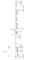
- FIG. 8 is a diagram showing the internal space of the first housing of the electronic device of FIG. 2 with a part of the first housing removed.
- speaker unit 30 includes two speaker units 31 and 32 and speaker box 40 includes two speaker boxes 41 and 42 .
- the speaker unit 31 is an example of a first speaker unit.
- the speaker unit 32 is an example of a second speaker unit.
- the speaker units 31 and 32 each include a diaphragm, a magnetic circuit, and the like. Since the configurations of the speaker units 32, 32 are publicly known, a detailed description of the configuration of the speaker units 31, 32 is omitted in this specification.
- the speaker boxes 41 and 42 are hollow and generally rectangular parallelepiped-shaped. Speaker boxes 41 and 42 have openings.
- the speaker unit 31 is fitted into the opening of the speaker box 41 . Thereby, the speaker unit 31 is attached to the speaker box 41 .
- the speaker unit 32 is fitted into the opening of the speaker box 42 . Thereby, the speaker unit 32 is attached to the speaker box 42 .
- one speaker unit is attached to one speaker box. That is, in Embodiment 1, the full-range speaker is housed in the housing 2 .
- a plurality of speaker units may be attached to one speaker box. That is, a 2-way speaker, a 3-way speaker, or the like may be housed in the housing 2 .
- the speaker box may have a through hole for communicating the inside and the outside of the speaker box in addition to the portion where the speaker unit is attached.
- the speaker unit 30 and the speaker box 40 constitute a bass reflex speaker.
- the speaker unit 31 and the speaker box 41 are located at the opposite end of the housing 2 to the hinge section 7 in the depth direction (Y direction) of the housing 2 in the width direction (X direction). ) at one end.
- the speaker unit 31 is arranged at a position facing the rear surface 231A of the bottom surface 231, which is the surface in which the through hole 23c is formed, among the surfaces of the recess 23A.
- the speaker unit 31 faces the area of the rear surface 231A in which the through holes 23c are formed.
- the entire speaker unit 31 it is not always necessary for the entire speaker unit 31 to be arranged at a position facing the entire rear surface 231A. In other words, at least a portion of the speaker unit 31 may be arranged at a position facing at least a portion of the rear surface 231A. Further, it is not always necessary for the entire speaker unit 31 to be arranged at a position facing the area of the rear surface 231A in which the through hole 23c is formed. It may be placed in a position where
- the speaker unit 32 and the speaker box 42 are located at the opposite end of the housing 2 to the hinge section 7 in the depth direction (Y direction) of the housing 2 in the width direction (X direction) of the housing 2. ) at the other end.
- the speaker unit 32 is arranged similarly to the speaker unit 31 . That is, the speaker unit 32 is arranged at a position facing the rear surface of the bottom surface 231, which is the surface on which the through hole 23c is formed, among the surfaces of the recess 23B.
- the entire speaker unit 32 it is not always necessary for the entire speaker unit 32 to be arranged at a position facing the entire rear surface of the bottom surface 231 . In other words, at least a portion of speaker unit 32 may be arranged at a position facing at least a portion of the rear surface of bottom surface 231 . Moreover, it is not always necessary for the entire speaker unit 32 to be arranged at a position facing the area on the back surface of the bottom surface 231 where the through hole 23c is formed. may be arranged at a position facing the .
- the electronic device 1 includes housings 2 and 3 and a speaker unit 30 .
- the housing 2 has an outer surface 11 on which the keyboard 4 is arranged and an outer surface 21 facing away from the outer surface 11 .
- the housing 3 accommodates the liquid crystal panel 6 and is connected to the housing 2 .
- the speaker unit 30 is arranged inside the housing 2 .
- a recess 23 is formed in the outer surface 21 .
- a through hole 23 c is formed in the bottom surface 231 of the recess 23 .
- At least part of speaker unit 30 faces at least part of rear surface 231A of bottom surface 231 of recess 23 in which through hole 23c is formed.
- the housing 2 has an outer surface 22 located between the peripheral edge portion 11A of the outer surface 11 and the peripheral edge portion 21A of the outer surface 21 .
- the recess 23 opens to the outer surface 22 .
- the recess 23 is opened not only to the outer surface 21 but also to the outer surface 22 . Thereby, the sound emitted by the speaker unit 30 can be transmitted to the outside of the electronic device 1 through the opening 23b of the outer surface 22. As shown in FIG.
- the recess 23 has a bottom surface 231 that is continuous with the outer surface 22 .
- the bottom surface 231 is inclined in a direction toward the outer surface 22 toward the outer surface 11 .
- the distance between the bottom surface 231 of the recess 23 and the outer surface 21 becomes wider toward the outer surface 22 .
- the sound of the speaker unit 30 that is transmitted to the outside of the electronic device through the opening 23 b of the outer surface 22 can be spread out in the recess 23 . Therefore, the sound pressure and quality of the sound emitted by the speaker unit 30 can be improved.
- the inclination angle ⁇ 1 of the bottom surface 231 with respect to the outer surface 21 is 1° or more and 45° or less.
- the sound emitted from the speaker unit 30 toward the desk, knees, etc. is reflected by the desk, knees, etc.
- the tilt angle ⁇ 1 is 0°
- most of the sound reflected by the desk, knees, etc. hits the bottom surface 231 .
- the sound is muffled between the desk, knees, etc., and the bottom surface 231, and may be difficult to reach the user's ears.
- the inclination angle ⁇ 1 is greater than 45°, the sound tends to escape in the horizontal direction, which may reduce the sound pressure.
- the sound hitting the bottom surface 231 can be reduced by setting the inclination angle ⁇ 1 to 1° or more.
- the inclination angle ⁇ 1 by setting the inclination angle ⁇ 1 to 45° or less, it is possible to suppress a decrease in sound pressure by utilizing the echo of sound between the desk, knees, etc., and the bottom surface 231. .
- the inclination angle ⁇ 1 is 45° or less. Therefore, with respect to the sound echo effect between the pair of side surfaces 232 and 233 based on the tilt angle ⁇ 2 and the sound echo effect between the pair of side surfaces 232 and 233 based on the tilt angle ⁇ 3, the tilt angle ⁇ 1 It is possible to greatly synergize the effect of sound reverberation based on
- the recess 23 has a pair of side surfaces 232, 233 facing each other and each continuous with the outer surfaces 21, 22.
- the pair of side surfaces 232 and 233 are inclined toward the outer surface 21 in a direction to increase the distance between the pair of side surfaces 232 and 233, and are also inclined toward the outer surface 22 in a direction to increase the distance between the pair of side surfaces 232 and 233. do.
- the distance between the pair of side surfaces 232 , 233 widens toward the outer surface 21 and widens toward the outer surface 22 . Accordingly, the sound of the speaker unit 31 that is transmitted to the outside of the electronic device 1 through the opening 23a of the outer surface 21 and the opening 23b of the outer surface 22 can be spread in the concave portion 23 . Therefore, the sound pressure and quality of the sound emitted by the speaker unit 31 can be improved.
- the inclination angle ⁇ 2 of each of the pair of side surfaces 232 and 233 inclined toward the outer surface 22 in the direction of increasing the distance between the pair of side surfaces 232 and 233 with respect to the virtual surface 25 orthogonal to the outer surfaces 21 and 22 is 5° or more. ° or less.
- the sound spread in the Y direction can be increased by setting the inclination angle ⁇ 2 to 5° or more.
- the inclination angle ⁇ 2 is set to 45° or less.
- the inclination angle ⁇ 2 is set to 45° or less.
- the inclination angle ⁇ 3 of each of the pair of side surfaces 232 and 233 inclined toward the outer surface 21 in the direction of increasing the distance between the pair of side surfaces 232 and 233 with respect to the virtual plane 25 orthogonal to the outer surfaces 21 and 22 is 5° or more. ° or less.
- the sound spread in the Z direction can be increased by setting the inclination angle ⁇ 3 to 5° or more.
- the inclination angle ⁇ 3 is set to 45° or less.
- the inclination angle ⁇ 3 is 45° or less. Therefore, for the effect of sound reflection between the desk and knees on which the electronic device 1 is placed and the bottom surface 231 and the effect of sound reflection between the pair of side surfaces 232 and 233 based on the inclination angle ⁇ 2, The sound reverberation effect based on the tilt angle ⁇ 3 can be greatly synergized.
- the outer surface 22 includes a right outer surface 22A located outside one longitudinal end of the keyboard 4 and a left outer surface located outside the other longitudinal end of the keyboard 4 and facing opposite to the right outer surface 22A. 22B.
- the recessed portion 23 includes a recessed portion 23A that opens to the right outer surface 22A and a recessed portion 23B that opens to the left outer surface 22B.
- Speaker unit 30 includes speaker unit 31 facing at least part of back surface 231A of bottom surface 231 of recess 23A in which through hole 23c is formed, and at least part of the back surface of bottom surface 231 of recess 23B in which through hole 23c is formed. and a speaker unit 32 facing to.
- the sound pressure and sound quality of the sounds emitted by the speaker units 31 and 32 are measured in a 360-degree direction centered on the electronic device 1 when the housing 2 is viewed from the direction perpendicular to the outer surface 21 (the Z direction). can be kept in good condition.
- the electronic device 1 further includes speaker boxes 41 and 42 that are arranged inside the housing 2 and to which the speaker units 31 and 32 are respectively mounted.
- the recess 23 has a bottom surface 231 and a pair of side surfaces 232 and 233 .
- the configuration of the recess 23 is not limited to this.
- the recess 23 may have a rectangular bottom surface in plan view and four side surfaces extending from all four sides of the rectangular bottom surface. Further, for example, at least a portion of the surface forming the recess 23 may be curved.
- the recess 23 may be configured with a spherical surface.
- the concave portions 23A and 23B are located at the ends of the housing 2 in the depth direction (Y direction) opposite to the hinge portion 7 and at both ends in the width direction (X direction) of the housing 2. formed in However, the recesses 23A and 23B may be formed at positions other than those described above.
- the recesses 23A and 23B may be formed at the end on the hinge part 7 side in the depth direction (Y direction), or may be formed at the center of the housing 2 in the depth direction (Y direction). good.
- the position of the recess 23A in the depth direction (Y direction) may be different from the position of the recess 23B in the depth direction (Y direction).
- the recesses 23A and 23B may be formed in the central portion of the outer surface 21 of the housing 2 instead of the peripheral edge portion 21A of the outer surface 21 of the housing 2 .
- recesses 23A and 23B each have opening 23a but do not have opening 23b.
- the recess 23A opens on the right outer surface 22A
- the recess 23B opens on the left outer surface 22B
- the recesses 23A and 23B may be opened in the front outer side surface 22C of the housing 2 or may be opened in the rear outer side surface 22D of the housing 2 .
- the recesses 23A and 23B are formed in the central portion of the outer surface 21 of the housing 2, the recesses 23A and 23B are not opened on the outer surface 22.
- Embodiment 1 two recesses 23 and 24 are formed in the outer surface 21 of the housing 2, but the number of recesses is not limited to two.
- One recess may be formed in the outer surface 21 of the housing 2, or three or more recesses may be formed.
- the speaker unit 30 and the speaker box 40 are arranged corresponding to each recess.
- the inclination angles ⁇ 2 of the pair of side surfaces 232 and 233 are the same, but they do not have to be the same.
- the inclination angles ⁇ 3 of the pair of side surfaces 232 and 233 are the same as each other, but they do not have to be the same as each other.
- only one of the pair of side surfaces 232 and 233 may be inclined with respect to the virtual plane 25 .
- FIG. 9 is a schematic bottom view of the first housing showing a modified example of the recess and its periphery in Embodiment 1 according to the present disclosure.
- FIG. 10 is a schematic right side view of the first housing showing a modified example of the recess and its surroundings in Embodiment 1 according to the present disclosure.
- FIG. 11 is a schematic bottom view of the first housing showing a modified example of the recess and its surroundings in Embodiment 1 according to the present disclosure.
- FIG. 12 is a schematic right side view of the first housing showing a modified example of the recess and its periphery in the first embodiment according to the present disclosure.
- the bottom surface 231 is inclined in a direction toward the outer surface 11 of the housing 3 toward the right outer surface 22A.
- the pair of side surfaces 232 and 233 are inclined toward the outer surface 21 in a direction in which the distance between the pair of side surfaces 232 and 233 is increased, and the distance between the pair of side surfaces 232 and 233 is increased toward the right outer surface 22A. tilt in the direction of
- the bottom surface 231 does not have to be inclined in the direction of approaching the outer surface 11 of the housing 2 toward the right outer surface 22A.
- the pair of side surfaces 232 and 233 are inclined toward the outer surface 21 in the direction of increasing the distance between the pair of side surfaces 232 and 233 as shown in FIG. It does not have to be inclined in the direction of increasing the distance between the pair of side surfaces 232 and 233 toward the .
- the recess 23 has a pair of side surfaces 232 and 233 that face each other and are continuous with the outer surface 21 .
- the pair of side surfaces 232 and 233 are inclined toward the outer surface 21 in a direction to increase the distance between the pair of side surfaces 232 and 233 .
- the distance between the pair of side surfaces 232 and 233 widens toward the outer surface 21 . Accordingly, the sound of the speaker unit 30 that is transmitted to the outside of the electronic device 1 through the opening 23 a of the outer surface 21 can be spread in the recess 23 . Therefore, the sound pressure and quality of the sound emitted by the speaker unit 30 can be improved.
- the bottom surface 231 does not have to be inclined in a direction toward the outer surface 11 of the housing 3 toward the right outer surface 22A.
- the pair of side surfaces 232 and 233 are inclined toward the right outer surface 22A as shown in FIG. It does not have to be inclined in the direction of increasing the distance between the pair of side surfaces 232 and 233 toward the .
- the recess 23 has a pair of side surfaces 232 and 233 facing each other and each continuous with the outer surface 22 .
- the pair of side surfaces 232 and 233 are inclined toward the outer surface 22 in a direction to increase the distance between the pair of side surfaces 232 and 233 .
- the distance between the pair of side surfaces 232 , 233 becomes wider toward the outer surface 22 . Accordingly, the sound of the speaker unit 30 that is transmitted to the outside of the electronic device 1 through the opening 23 b of the outer surface 22 can be spread in the recess 23 . Therefore, the sound pressure and quality of the sound emitted by the speaker unit 30 can be improved.
- the through hole 23c is formed only in the bottom surface 231 of the surfaces of the recess 23, but the through hole 23c is not limited to the bottom surface 231.
- the through holes 23c may be formed in both the bottom surface 231 and the pair of side surfaces 232 and 233, or may be formed only in the pair of side surfaces 232 and 233.
- the speaker unit 30 is arranged at a position facing the rear surface of the surface of the recess 23 in which the through hole 23c is formed.
- the speaker unit 30 is arranged at a position facing the rear surface of the side surface 232 .
- the speaker unit 30 and the speaker box 40 are housed in the internal space of the housing 2 .
- the electronic device 1 does not have to include the speaker box 40 .
- the speaker unit 30 is housed in the internal space of the housing 2, but the speaker box 40 is not.
- case 10 has outer surface 11 and case 20 has outer surfaces 21 and 22 .
- case 10 may have outer surfaces 11 and 22 and case 20 may have outer surface 21 .
- Embodiment 1 a notebook personal computer (laptop PC) has been described as an example of the electronic device 1, but the electronic device 1 is not limited to this.
- the present disclosure is useful for, for example, electronic devices (eg, laptop PCs, etc.) because it is possible to suppress a decrease in the sound pressure of the sound emitted by the speaker unit.
- electronic devices eg, laptop PCs, etc.
- 1 electronic device 2 housing (first housing) 3 housing (second housing) 4 keyboard 6 liquid crystal panel (display) 11 outer surface (first outer surface) 11A Periphery 21 Outer surface (second outer surface) 21A peripheral portion 22 outer surface (third outer surface) 22A right outer surface 22B left outer surface 23 recess 23A recess (first recess) 23B recess (second recess) 23a, 23b opening 23c through hole 231 bottom surface 231A rear surface 232 side surface 233 side surface 25 virtual surface 30 speaker unit 31 speaker unit (first speaker unit) 32 speaker unit (second speaker unit) 40 speaker box 41 speaker box 42 speaker box ⁇ 1 tilt angle ⁇ 2 tilt angle ⁇ 3 tilt angle
Landscapes
- Engineering & Computer Science (AREA)
- Theoretical Computer Science (AREA)
- Computer Hardware Design (AREA)
- General Engineering & Computer Science (AREA)
- Physics & Mathematics (AREA)
- Human Computer Interaction (AREA)
- General Physics & Mathematics (AREA)
- Microelectronics & Electronic Packaging (AREA)
- Mathematical Physics (AREA)
- Telephone Set Structure (AREA)
- Details Of Audible-Bandwidth Transducers (AREA)
Priority Applications (2)
| Application Number | Priority Date | Filing Date | Title |
|---|---|---|---|
| JP2023514558A JP7742528B2 (ja) | 2021-04-15 | 2022-03-25 | 電子機器 |
| US18/375,527 US12554294B2 (en) | 2021-04-15 | 2023-10-01 | Electronic device |
Applications Claiming Priority (2)
| Application Number | Priority Date | Filing Date | Title |
|---|---|---|---|
| JP2021-069182 | 2021-04-15 | ||
| JP2021069182 | 2021-04-15 |
Related Child Applications (1)
| Application Number | Title | Priority Date | Filing Date |
|---|---|---|---|
| US18/375,527 Continuation US12554294B2 (en) | 2021-04-15 | 2023-10-01 | Electronic device |
Publications (1)
| Publication Number | Publication Date |
|---|---|
| WO2022220068A1 true WO2022220068A1 (ja) | 2022-10-20 |
Family
ID=83640628
Family Applications (1)
| Application Number | Title | Priority Date | Filing Date |
|---|---|---|---|
| PCT/JP2022/014375 Ceased WO2022220068A1 (ja) | 2021-04-15 | 2022-03-25 | 電子機器 |
Country Status (3)
| Country | Link |
|---|---|
| US (1) | US12554294B2 (https=) |
| JP (1) | JP7742528B2 (https=) |
| WO (1) | WO2022220068A1 (https=) |
Citations (2)
| Publication number | Priority date | Publication date | Assignee | Title |
|---|---|---|---|---|
| JP2002368853A (ja) * | 2001-06-08 | 2002-12-20 | Matsushita Electric Ind Co Ltd | 携帯無線装置 |
| JP2010154357A (ja) * | 2008-12-25 | 2010-07-08 | Kyocera Corp | 携帯電子機器 |
Family Cites Families (16)
| Publication number | Priority date | Publication date | Assignee | Title |
|---|---|---|---|---|
| KR0162601B1 (ko) * | 1996-01-17 | 1999-01-15 | 김광호 | 컴퓨터 장치 |
| US5838537A (en) * | 1996-08-21 | 1998-11-17 | Gateway 2000, Inc. | Retractable speakers for portable computer |
| JP3388111B2 (ja) * | 1996-10-24 | 2003-03-17 | 富士通株式会社 | スピーカを有する情報処理装置 |
| US6040978A (en) * | 1997-11-26 | 2000-03-21 | Gateway 2000, Inc. | Portable computer having folding speakers |
| WO1999064949A1 (en) * | 1998-06-10 | 1999-12-16 | Sanyo Electric Co., Ltd. | Folding electronic apparatus |
| US6078497A (en) * | 1999-01-29 | 2000-06-20 | Hewlett-Packard Company | Portable electronic device having an enhanced speaker system |
| JP3534393B2 (ja) | 2000-04-14 | 2004-06-07 | インターナショナル・ビジネス・マシーンズ・コーポレーション | 電子部品ユニットの電気的接続構造、コンピュータ装置及び電子機器 |
| US6794798B2 (en) * | 2001-03-30 | 2004-09-21 | Taiyo Yuden Co., Ltd. | Display device and electronic equipment employing piezoelectric speaker |
| US6600827B2 (en) * | 2001-10-03 | 2003-07-29 | Kuan-Yu Chou | Externally mounted speaker for notebook computer |
| US7200000B1 (en) * | 2006-03-09 | 2007-04-03 | Inventec Corporation | Notebook with an audio player |
| CN100517166C (zh) * | 2006-06-02 | 2009-07-22 | 鸿富锦精密工业(深圳)有限公司 | 笔记本电脑 |
| JP2008072239A (ja) * | 2006-09-12 | 2008-03-27 | Sony Corp | 携帯電子機器 |
| JP5306944B2 (ja) | 2009-08-31 | 2013-10-02 | 日本写真印刷株式会社 | スピーカ兼用タッチパネルの実装構造 |
| US8369561B2 (en) * | 2010-03-24 | 2013-02-05 | Dell Products L.P. | Sideways extending speaker apparatus and methods |
| JP2012227854A (ja) | 2011-04-22 | 2012-11-15 | Sony Corp | 電子機器 |
| JP2018121175A (ja) | 2017-01-24 | 2018-08-02 | Necパーソナルコンピュータ株式会社 | 電子機器 |
-
2022
- 2022-03-25 WO PCT/JP2022/014375 patent/WO2022220068A1/ja not_active Ceased
- 2022-03-25 JP JP2023514558A patent/JP7742528B2/ja active Active
-
2023
- 2023-10-01 US US18/375,527 patent/US12554294B2/en active Active
Patent Citations (2)
| Publication number | Priority date | Publication date | Assignee | Title |
|---|---|---|---|---|
| JP2002368853A (ja) * | 2001-06-08 | 2002-12-20 | Matsushita Electric Ind Co Ltd | 携帯無線装置 |
| JP2010154357A (ja) * | 2008-12-25 | 2010-07-08 | Kyocera Corp | 携帯電子機器 |
Also Published As
| Publication number | Publication date |
|---|---|
| US12554294B2 (en) | 2026-02-17 |
| JP7742528B2 (ja) | 2025-09-22 |
| US20240028089A1 (en) | 2024-01-25 |
| JPWO2022220068A1 (https=) | 2022-10-20 |
Similar Documents
| Publication | Publication Date | Title |
|---|---|---|
| US7746627B2 (en) | Portable electronic apparatus with improved audio quality through a curved and sloped surface of a housing | |
| CN103299654B (zh) | 显示装置 | |
| EP3646616B1 (en) | Electro-acoustical transducer arrangements of a sound system | |
| TWI669593B (zh) | 可調式顯示器殼體總成 | |
| JP6686117B1 (ja) | 電子機器 | |
| TW201944197A (zh) | 筆記型電腦 | |
| JP2020140406A (ja) | 電子機器 | |
| JP2017134758A (ja) | 情報処理装置 | |
| JP2020120298A (ja) | 電子機器 | |
| TWI599241B (zh) | 可加強低音音效的揚聲裝置及相關電子裝置 | |
| WO2022220068A1 (ja) | 電子機器 | |
| JP6857704B1 (ja) | 携帯用情報機器 | |
| JP2000172373A (ja) | スピーカ収納式パーソナルコンピュータ | |
| TWI583207B (zh) | 手持式電子裝置 | |
| JP2011055279A (ja) | 通信装置 | |
| US7791877B2 (en) | Portable apparatus incorporating a sound output device | |
| JP6758455B1 (ja) | 電子機器 | |
| CN115460307B (zh) | 电子设备及电子设备发声方法 | |
| EP3133830A1 (en) | Speaker and electronic device having the speaker | |
| CN218352526U (zh) | 电子设备 | |
| KR200148503Y1 (ko) | 노트북 컴퓨터의 스피커 조립구조 | |
| CN103428589A (zh) | 便携式电子装置 | |
| US12425773B2 (en) | Electronic device including acoustic actuator | |
| JP2003280766A (ja) | スピーカユニット内蔵情報処理装置 | |
| JP7775697B2 (ja) | 放音装置及び電子楽器 |
Legal Events
| Date | Code | Title | Description |
|---|---|---|---|
| 121 | Ep: the epo has been informed by wipo that ep was designated in this application |
Ref document number: 22787993 Country of ref document: EP Kind code of ref document: A1 |
|
| WWE | Wipo information: entry into national phase |
Ref document number: 2023514558 Country of ref document: JP |
|
| NENP | Non-entry into the national phase |
Ref country code: DE |
|
| 122 | Ep: pct application non-entry in european phase |
Ref document number: 22787993 Country of ref document: EP Kind code of ref document: A1 |