WO2022220059A1 - 超音波モータ - Google Patents
超音波モータ Download PDFInfo
- Publication number
- WO2022220059A1 WO2022220059A1 PCT/JP2022/014301 JP2022014301W WO2022220059A1 WO 2022220059 A1 WO2022220059 A1 WO 2022220059A1 JP 2022014301 W JP2022014301 W JP 2022014301W WO 2022220059 A1 WO2022220059 A1 WO 2022220059A1
- Authority
- WO
- WIPO (PCT)
- Prior art keywords
- stator
- hole
- vibrating body
- view
- plan
- Prior art date
- Legal status (The legal status is an assumption and is not a legal conclusion. Google has not performed a legal analysis and makes no representation as to the accuracy of the status listed.)
- Ceased
Links
Images





Classifications
-
- H—ELECTRICITY
- H02—GENERATION; CONVERSION OR DISTRIBUTION OF ELECTRIC POWER
- H02N—ELECTRIC MACHINES NOT OTHERWISE PROVIDED FOR
- H02N2/00—Electric machines in general using piezoelectric effect, electrostriction or magnetostriction
- H02N2/10—Electric machines in general using piezoelectric effect, electrostriction or magnetostriction producing rotary motion, e.g. rotary motors
- H02N2/16—Electric machines in general using piezoelectric effect, electrostriction or magnetostriction producing rotary motion, e.g. rotary motors using travelling waves, i.e. Rayleigh surface waves
- H02N2/166—Motors with disc stator
-
- H—ELECTRICITY
- H02—GENERATION; CONVERSION OR DISTRIBUTION OF ELECTRIC POWER
- H02N—ELECTRIC MACHINES NOT OTHERWISE PROVIDED FOR
- H02N2/00—Electric machines in general using piezoelectric effect, electrostriction or magnetostriction
- H02N2/10—Electric machines in general using piezoelectric effect, electrostriction or magnetostriction producing rotary motion, e.g. rotary motors
- H02N2/103—Electric machines in general using piezoelectric effect, electrostriction or magnetostriction producing rotary motion, e.g. rotary motors by pressing one or more vibrators against the rotor
-
- H—ELECTRICITY
- H02—GENERATION; CONVERSION OR DISTRIBUTION OF ELECTRIC POWER
- H02N—ELECTRIC MACHINES NOT OTHERWISE PROVIDED FOR
- H02N2/00—Electric machines in general using piezoelectric effect, electrostriction or magnetostriction
- H02N2/10—Electric machines in general using piezoelectric effect, electrostriction or magnetostriction producing rotary motion, e.g. rotary motors
- H02N2/12—Constructional details
Definitions
- the present invention relates to ultrasonic motors.
- Patent Document 1 discloses an example of an ultrasonic motor.
- the moving body is rotated by a standing wave generated in the vibrating body.
- a moving body is arranged on one main surface side of the vibrating body, and a vibrating body fixture is arranged on the other main surface side.
- the vibrating body is provided with a small hole through which the rotating shaft of the moving body is inserted.
- the vibrating body fixtures fix the main surface of the vibrating body around the small holes and at the vibration nodes of the vibrating body.
- the vibrating body receives a reaction force from the rotor side when a force is applied to rotate the moving body, that is, the rotor. Therefore, it is necessary to firmly fix the vibrating body in order to prevent the vibrating body from rotating due to the reaction force.
- the vibrating body is also fixed around the small hole. Since the portion of the vibrating body around the small hole vibrates, if such a portion is firmly fixed, the vibration of the vibrating body will be hindered. Therefore, the characteristics of the ultrasonic motor may deteriorate.
- An object of the present invention is to provide an ultrasonic motor in which the vibrating body can be effectively fixed and the vibration of the vibrating body is less likely to be disturbed.
- An ultrasonic motor includes a first main surface and a second main surface facing each other, and a through hole penetrating in a direction in which the first main surface and the second main surface face each other. and a piezoelectric element provided on the first main surface of the vibrating body; and a rotor in contact with the second main surface of the vibrating body.
- stator fixing member having a body portion arranged on the first main surface side of the vibrating body, and a detent portion extending from the body portion toward the vibrating body side, wherein the stator fixing member
- the anti-rotation portion and the through hole of the stator have a polygonal shape in plan view, the number of vertexes of the anti-rotation portion and the through hole are the same, and the anti-rotation portion and the through hole are mated.
- the vibrating body can be effectively fixed, and the vibration of the vibrating body is less likely to be disturbed.
- FIG. 1 is a front cross-sectional view of an ultrasonic motor according to a first embodiment of the invention.
- FIG. 2 is an exploded perspective view of the ultrasonic motor according to the first embodiment of the invention.
- FIG. 3 is a plan view showing the vicinity of the anti-rotation portion and the first projecting portion of the stator fixing member according to the first embodiment of the present invention.
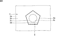
- FIG. 4 is a plan view showing the vicinity of the through hole of the vibrator and the anti-rotation portion of the stator fixing member according to the first embodiment of the present invention.
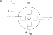
- FIG. 5 is a bottom view of the stator in the first embodiment of the invention.
- FIG. 6 is a front sectional view of the first piezoelectric element in the first embodiment of the invention.
- FIGS. 8(a) to 8(c) are schematic bottom views of the stator for explaining traveling waves excited in the first embodiment.
- FIG. 9 is a bottom view for explaining the relationship between the shape of the through holes and the positions of the piezoelectric elements in the stator of the first embodiment of the invention.
- FIG. 10 is a bottom view for explaining the relationship between the shape of the through holes and the positions of the piezoelectric elements in the stator of the second embodiment of the invention.
- FIG. 1 is a front cross-sectional view of an ultrasonic motor according to the first embodiment of the present invention.
- FIG. 2 is an exploded perspective view of the ultrasonic motor according to the first embodiment.
- the ultrasonic motor 1 has a stator 2, a rotor 4, a case 5, and a shaft member 10.
- a case 5 houses the stator 2 and the rotor 4 .
- the case 5 is composed of a stator fixing member 6 as a first case member and a cap member 18 as a second case member.
- the stator 2 and rotor 4 are in contact.
- a traveling wave generated in the stator 2 causes the rotor 4 to rotate.
- the shaft member 10 is inserted through the stator 2 and the rotor 4 and reaches the outside of the case 5 .
- the shaft member 10 rotates.
- the rotor 4 may include the shaft member 10 .
- a specific configuration of the ultrasonic motor 1 will be described below.
- the stator 2 has a vibrating body 3.
- the vibrating body 3 is disc-shaped.
- the vibrating body 3 has a first main surface 3a and a second main surface 3b.
- the first main surface 3a and the second main surface 3b face each other.
- the axial direction Z is a direction connecting the first main surface 3a and the second main surface 3b and along the rotation center axis.
- the shaft member 10 extends parallel to the axial direction Z.
- the direction viewed from the axial direction Z may be described as plan view or bottom view. Note that the plan view is the direction viewed from above in FIG. 1, and the bottom view is the direction viewed from below.
- the direction seen from the second main surface 3b side of the vibrating body 3 to the first main surface 3a side is the plan view
- the direction seen from the first main surface 3a side to the second main surface 3b side is the bottom surface. It is sight.
- a through hole 3c is provided in the central portion of the vibrating body 3.
- the vibrating body 3 has an inner surface 3d facing the through hole 3c.
- the through hole 3c has a regular pentagonal shape. That is, the shape of the through hole 3c in plan view is a regular pentagon.
- the through hole 3c may be located in a region including the center in the axial direction.
- the shape of the through hole 3c in plan view may be, for example, a polygonal shape other than a pentagonal shape.
- the through hole 3c preferably has a regular polygonal shape in plan view.
- the shape of the vibrating body 3 is not limited to a disc shape.
- the shape of the vibrating body 3 in plan view may be, for example, a regular polygon such as a regular hexagon, a regular octagon, or a regular decagon.
- the vibrating body 3 is made of an appropriate metal. Note that the vibrating body 3 does not necessarily have to be made of metal.
- the vibrating body 3 may be composed of other elastic bodies such as ceramics, silicon material, or synthetic resin, for example.
- the first main surface 3a of the vibrating body 3 is provided with a plurality of piezoelectric elements.
- a traveling wave is generated by vibrating the vibrating body 3 with a plurality of piezoelectric elements.
- the rotor 4 is in contact with the second main surface 3b of the vibrating body 3.
- the rotor 4 is disc-shaped.
- a through hole 4 c is provided in the central portion of the rotor 4 .
- the through hole 4c may be positioned in a region including the center in the axial direction.
- the shape of the rotor 4 is not limited to the above.
- the shape of the rotor 4 may be, for example, a regular polygon such as a regular hexagon, a regular octagon, or a regular decagon in plan view.
- the stator fixing member 6 is a flange in this embodiment.
- the stator fixing member 6 has a body portion 7 and a detent portion 8 .
- the body portion 7 has a circular shape.
- the body portion 7 is arranged on the first main surface 3 a side of the vibrating body 3 .
- a central portion of the body portion 7 is provided with a first projecting portion 7a.
- the first projecting portion 7a extends in a direction perpendicular to the main surface of the main body portion 7.
- the first protrusion 7 a protrudes inside the case 5 . Note that the first projecting portion 7a may not necessarily be provided.
- a detent part 8 is connected to the first projecting part 7a.
- a detent portion 8 extends toward the vibrating body 3 from the first projecting portion 7a.
- the anti-rotation portion 8 is provided integrally with the first projecting portion 7a.
- the anti-rotation portion 8 is inserted through the through hole 3 c of the vibrating body 3 .
- the anti-rotation portion 8 is a portion that fixes the vibrating body 3 of the stator 2 and suppresses the rotation of the vibrating body 3 .
- FIG. 3 is a plan view showing the vicinity of the anti-rotation portion and the first projecting portion of the stator fixing member in the first embodiment.
- FIG. 4 is a plan view showing the vicinity of the through-hole of the vibrator and the anti-rotation portion of the stator fixing member in the first embodiment.
- locking part 8 is shown by the dashed-dotted line.
- the first projecting portion 7a has a circular shape in plan view. More specifically, the first protrusion 7a has a cylindrical shape. The first projecting portion 7a surrounds the anti-rotation portion 8 in plan view.
- the shape of the first projecting portion 7a is not limited to the above.
- the anti-rotation portion 8 has a regular pentagonal shape in plan view. Therefore, the number of vertexes of the polygonal shape in the plan view of the anti-rotation portion 8 and the through hole 3c of the stator 2 is the same.
- the shape of the anti-rotation portion 8 in plan view may be a polygonal shape other than a pentagon depending on the shape of the through hole 3c. It is preferable that the anti-rotation portion 8 has a regular polygonal shape in a plan view.
- the anti-rotation portion 8 includes an outer surface 8a. The outer surface 8a is in contact with the inner surface 3d of the vibrating body 3 of the stator 2. As shown in FIG. More specifically, the anti-rotation portion 8 and the through hole 3c are fitted.
- a through hole 8c is provided in the anti-rotation portion 8.
- the through hole 8c has a circular shape.
- one continuous through hole is provided in the anti-rotation portion 8 and the first projecting portion 7a.
- Through hole 8c is part of the through hole.
- a shaft member 10 is inserted through the one continuous through hole, the through hole 3 c of the stator 2 and the through hole 4 c of the rotor 4 .
- the through hole 3c of the stator 2 overlaps the through hole 8c of the anti-rotation portion 8 when viewed in a direction orthogonal to the axial direction Z. As shown in FIG.
- stator fixing member 6 As the material of the stator fixing member 6, for example, resin, metal or ceramics can be used. It is desirable that the stator fixing member 6 and the stator 2 are electrically insulated from each other.
- the present embodiment is characterized in that the anti-rotation portion 8 and the through hole 3c of the stator 2 have a polygonal shape in plan view, the number of vertexes of the anti-rotation portion 8 and the through hole 3c are the same, and the anti-rotation portion 8 and the through hole 3c are fitted.
- the vibrating body 3 of the stator 2 can be effectively fixed.
- the vibrating body 3 is not firmly fixed in the stator fixing member 6 except for the anti-rotation portion 8, the vibration of the vibrating body 3 is less likely to be hindered.
- the stator fixing member 6 has a second projecting portion 7b.
- the second protruding portion 7b protrudes from the main body portion 7 toward the outside of the case 5.
- the second protrusion 7b has a cylindrical shape.
- the second projecting portion 7b, the first projecting portion 7a, and the anti-rotation portion 8 are provided with one continuous through hole.
- the inner diameter of the second projecting portion 7b is larger than the inner diameter of the first projecting portion 7a and the inner diameter of the anti-rotation portion 8 .
- a first bearing portion 19A is provided in the second projecting portion 7b.
- the shaft member 10 is inserted through the first bearing portion 19A.
- the shaft member 10 protrudes outside the case 5 through the first bearing portion 19A.
- the second projecting portion 7b is not limited to a cylindrical shape, and may be cylindrical.
- the stator fixing member 6 may not necessarily be provided with the second projecting portion 7b.
- the stator fixing member 6 may not be the first case member, and a first case member separate from the stator fixing member 6 may be provided.
- the stator fixing member 6 is a part of the case 5, the size of the ultrasonic motor 1 can be reduced.
- the cap member 18 has a projecting portion 18a.
- the protruding portion 18 a protrudes outside the case 5 .
- the projecting portion 18a is cylindrical.
- Metal, ceramics, resin, or the like, for example, can be used for the cap member 18 .
- the second case member of case 5 is cap member 18 .
- the second case member is not limited to the cap member 18 .
- a case in which the stator 2, the rotor 4, and the like are accommodated may be constructed.
- a second bearing portion 19B is provided in the projecting portion 18a.
- the shaft member 10 is inserted through the second bearing portion 19B.
- the shaft member 10 protrudes outside the case 5 through the second bearing portion 19B.
- a retaining ring 17 is provided on the shaft member 10 .
- the retaining ring 17 has an annular shape.
- the retaining ring 17 surrounds the shaft member 10 in plan view. More specifically, the inner peripheral edge of the retaining ring 17 is positioned within the shaft member 10 .
- the retaining ring 17 contacts the first bearing portion 19A from the outside in the axial direction Z. As shown in FIG. Thereby, the positional deviation of the shaft member 10 can be suppressed.
- materials for the shaft member 10 and the snap ring 17 for example, metal or resin can be used.
- sliding bearings or bearings may be used for the first bearing portion 19A and the second bearing portion 19B.
- the rotor 4 has a concave portion 4a and a side wall portion 4b.
- the recess 4a is circular in plan view.
- the side wall portion 4b is a portion surrounding the recessed portion 4a.
- the rotor 4 is in contact with the stator 2 at the end face 4d of the side wall portion 4b.
- the concave portion 4a and the side wall portion 4b may not be provided.
- the rotor 4 and the shaft member 10 are configured separately.
- the rotor 4 and the shaft member 10 may be integrally configured. That is, the rotor 4 may include the shaft member 10 .
- An elastic member 12 is provided on the rotor 4 .
- the elastic member 12 sandwiches the rotor 4 together with the stator 2 in the axial direction Z.
- the elastic member 12 has an annular shape. Note that the shape of the elastic member 12 is not limited to the above.
- a material of the elastic member 12 for example, rubber or resin can be used. However, the elastic member 12 may not be provided.
- a spring member 16 is arranged on the second bearing portion 19B side of the rotor 4 . More specifically, the spring member 16 of this embodiment is a leaf spring made of metal. An opening 16 c is provided in the central portion of the spring member 16 . The shaft member 10 is inserted through the opening 16c. The shaft member 10 has a wide portion 10a. The width of the wide portion 10 a of the shaft member 10 is wider than the width of other portions of the shaft member 10 . The width of the shaft member 10 is a dimension along the direction perpendicular to the axial direction Z of the shaft member 10 . The inner peripheral edge portion of the spring member 16 is in contact with the wide portion 10a. Thereby, positional deviation between the spring member 16 and the shaft member 10 can be suppressed.
- the material and configuration of the spring member 16 are not limited to the above.
- the configuration of the shaft member 10 is also not limited to the above.
- a friction material may be fixed to the surface of the rotor 4 on the stator 2 side. Thereby, the frictional force applied between the oscillator 3 of the stator 2 and the rotor 4 can be stabilized. In this case, the rotor 4 can be efficiently rotated, and the ultrasonic motor 1 can be efficiently rotationally driven.
- a plurality of protrusions 3e are provided on the second main surface 3b of the vibrating body 3.
- the plurality of protrusions 3 e are portions of the vibrating body 3 that are in contact with the rotor 4 .
- Each protrusion 3 e protrudes in the axial direction Z from the second main surface 3 b of the vibrating body 3 .
- the plurality of protrusions 3e are arranged in an annular shape. Since the plurality of protrusions 3e protrude from the second main surface 3b in the axial direction Z, when a traveling wave is generated in the vibrating body 3, the tips of the plurality of protrusions 3e are displaced to a greater extent. Therefore, the traveling wave generated in the stator 2 can efficiently rotate the rotor 4 .
- the plurality of protrusions 3e may not necessarily be provided.
- FIG. 5 is a bottom view of the stator in the first embodiment.
- a plurality of piezoelectric elements are provided on the first main surface 3 a of the vibrating body 3 . More specifically, the plurality of piezoelectric elements are a first piezoelectric element 13A, a second piezoelectric element 13B, a third piezoelectric element 13C and a fourth piezoelectric element 13D.
- the plurality of piezoelectric elements are distributed along the circulating direction of the traveling wave so as to generate a traveling wave circulating around an axis parallel to the axial direction Z. As shown in FIG. When viewed from the axial direction Z, the first piezoelectric element 13A and the third piezoelectric element 13C face each other across the axis.
- the second piezoelectric element 13B and the fourth piezoelectric element 13D face each other across the axis.
- FIG. 6 is a front sectional view of the first piezoelectric element in the first embodiment.
- the first piezoelectric element 13A has a piezoelectric body 14.
- the piezoelectric body 14 has a third principal surface 14a and a fourth principal surface 14b.
- the third main surface 14a and the fourth main surface 14b face each other.
- the first piezoelectric element 13A has a first electrode 15A and a second electrode 15B.
- a first electrode 15A is provided on the third main surface 14a of the piezoelectric body 14, and a second electrode 15B is provided on the fourth main surface 14b.
- the first electrode 15A and the second electrode 15B are electrodes for exciting the first piezoelectric element 13A.
- the second piezoelectric element 13B, the third piezoelectric element 13C, and the fourth piezoelectric element 13D are configured similarly to the first piezoelectric element 13A.
- Each piezoelectric element has a rectangular shape in plan view. The shape of each piezoelectric element in plan view is not limited to the above, and may be, for example, circular or elliptical
- the first electrode 15A is attached to the first main surface 3a of the vibrating body 3 with an adhesive.
- the thickness of this adhesive is very thin. Therefore, the first electrode 15A is electrically connected to the vibrating body 3. As shown in FIG.
- the stator 2 should have at least the first piezoelectric element 13A and the second piezoelectric element 13B. Alternatively, it may have one piezoelectric element divided into a plurality of regions. In this case, for example, each region of the piezoelectric element may be polarized in different directions. In this specification, one piezoelectric element and a plurality of piezoelectric elements each having a different polarization direction for each region may be referred to as a plurality of polarized piezoelectric elements. In this embodiment, the plurally polarized piezoelectric elements vibrate the vibrating body 3 in a vibration mode including nodal lines extending in the circumferential direction and the radial direction.
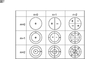
- FIG. 7 is a schematic diagram for explaining each vibration mode. Specifically, FIG. 7 shows the phase of vibration in each region of the vibrating body 3 when viewed from above. Regions marked with a + sign and regions marked with a - sign indicate that the vibration phases are opposite to each other.
- the vibration mode can be expressed as a B(m, n) mode.
- the B(m, n) mode is used. That is, the number m of nodal lines extending in the circumferential direction and the number n of nodal lines extending in the radial direction may be 0 or any natural number.
- WO2010/061508A1 a structure in which a plurality of piezoelectric elements are distributed in the circumferential direction and driven to generate traveling waves is disclosed in WO2010/061508A1, for example. It should be noted that the detailed description of the structure for generating this traveling wave will be omitted by omitting not only the following description but also the configuration described in WO2010/061508A1.
- FIGS. 8(a) to 8(c) are schematic bottom views of the stator for explaining traveling waves excited in the first embodiment.
- FIGS. 8(a) to 8(c) in the gray scale, the closer to black, the greater the stress in one direction, and the closer to white, the greater the stress in the other direction.
- FIG. 8(a) shows a three-wave standing wave X
- FIG. 8(b) shows a three-wave standing wave Y.
- the first to fourth piezoelectric elements 13A to 13D are arranged with a central angle of 90°.
- the central angle is determined by multiplying the angle of one wave of 120° by 3/4 to determine the angle of 90°.
- the first piezoelectric element 13A is arranged at a predetermined place where the amplitude of the three-wave standing wave X is large, and the second to fourth piezoelectric elements 13B to 13D are arranged at intervals of 90° of the central angle.
- three standing waves X and Y having vibration phases different by 90° are excited, and the two are synthesized to generate a traveling wave shown in FIG. 8(c).
- A+, A-, B+, and B- in FIGS. 8(a) to 8(c) indicate the polarization directions of the piezoelectric body .
- + means that it is polarized from the third main surface 14a toward the fourth main surface 14b in the thickness direction.
- - indicates that it is polarized in the opposite direction.
- A indicates the first piezoelectric element 13A and the third piezoelectric element 13C
- B indicates the second piezoelectric element 13B and the fourth piezoelectric element 13D.
- the configuration for generating traveling waves is not limited to the configurations shown in FIGS. 8A to 8C, and various known configurations for generating traveling waves can be used.
- the main body portion 7 of the stator fixing member 6 has the first projecting portion 7a as in the present embodiment.
- the first projecting portion 7a preferably has a circular shape in plan view. Thereby, the stator 2 can be arranged more reliably and stably.
- the stator fixing member 6 since the stator 2 is firmly fixed at the anti-rotation portion 8, it is not necessary to firmly fix the stator 2 at the first protruding portion 7a. Therefore, even if it has the 1st protrusion part 7a, it is hard to inhibit the vibration of the vibrating body 3 of the stator 2.
- the diameter of the rotation preventing portion 8 is larger than the diameter of the first protrusion 7a in order to support the stator 2 by the first projecting portion 7a. It is necessary to increase the diameter of the protrusion 7a.
- the anti-rotation portion 8 is polygonal in plan view as in the present embodiment, for example, the diameter of the circumscribed circle of the polygon and the diameter of the first projecting portion 7a are equal to each other. Even if they are the same, the stator 2 can be supported by the first projections 7a. Thus, the diameter of the first projecting portion 7a can be reduced.
- the diameter of the first projecting portion 7a may be larger than the diameter of the circumscribed circle of the polygon.
- the stator 2 can be favorably supported even if the diameter of the first projecting portion 7a is made smaller than when the anti-rotation portion 8 is circular in plan view. Therefore, the entire range of the portion that supports the stator 2 by the first projecting portion 7a can be brought closer to the through hole 3c of the stator 2. As shown in FIG. Therefore, inhibition of the vibration of the stator 2 can be effectively suppressed, and deterioration of the characteristics of the ultrasonic motor 1 can be effectively suppressed.
- the anti-rotation portion 8 of the stator fixing member 6 and the through hole 3c of the stator 2 have a regular polygonal shape. Thereby, the stability of rotational driving of the ultrasonic motor 1 can be easily enhanced.
- the anti-rotation portion 8 and the through hole 3c of the stator 2 have the same number of vertices in the polygonal shape in plan view.
- the number of vertices of the anti-rotation portion 8 and the number of vertexes of the through hole 3c are preferably five or seven. That is, it is preferable that the anti-rotation portion 8 and the through hole 3c have a pentagonal shape or a heptagonal shape in plan view.
- the size of the diameter of the inscribed circle of the anti-rotation portion 8 in plan view is based on the width of the shaft member 10 regardless of the number of vertices of the anti-rotation portion 8 .
- the distance between the inscribed circle and the circumscribed circle in plan view of the anti-rotation portion 8 increases as the number of vertices of the anti-rotation portion 8 decreases. If the diameter of the inscribed circle is constant and the distance between the inscribed circle and the circumscribed circle is long, the diameter of the circumscribed circle increases. In this case, the diameter of the through hole 3c of the stator 2 needs to be increased.
- the ultrasonic motor 1 can be miniaturized.
- the number of vertexes of the anti-rotation portion 8 is too large, the shape of the anti-rotation portion 8 in plan view will approach a circle.
- the number of vertexes of the anti-rotation portion 8 is seven or less, the resistance of the stator 2 against the rotation of the vibrating body 3 can be effectively increased, and the vibrating body 3 can be effectively fixed. .
- the vibrating body 3 of the stator 2 vibrates in the B(m, n) mode.
- the vibration of the vibrating body 3 there are n nodal lines extending in the radial direction.
- a ⁇ n it is preferable that a ⁇ n.
- the relationship between the number a and the number n is not limited to the above.
- FIG. 9 is a bottom view for explaining the relationship between the shape of the through holes and the positions of the piezoelectric elements in the stator of the first embodiment.
- a dashed-dotted line in FIG. 9 indicates a straight line connecting the apex of the through hole 3c of the vibrating body 3 in the stator 2 and the center of the through hole 3c.
- Each of the five straight lines shown in FIG. 9 passes through one vertex of the plurality of vertices of the through hole 3c.
- Each straight line does not pass through the center of each piezoelectric element in plan view.
- the first electrode 15A is provided on the entire third main surface 14a of the piezoelectric body 14.
- a second electrode 15B is provided over the entire fourth main surface 14b. Therefore, the center of the first electrode 15A and the center of the second electrode 15B of each piezoelectric element are not positioned on each straight line shown in FIG.
- the first electrode 15A and the second electrode 15B are electrodes for excitation.
- the through hole 3c of the stator 2 has a non-circular shape in plan view, it has asymmetry in the circumferential direction.
- the arrangement of the first electrodes 15A and the second electrodes 15B of the plurality of piezoelectric elements also has asymmetry in the winding direction.
- the centers of the first electrode 15A and the second electrode 15B of each piezoelectric element are positioned on the straight line connecting the apex of the through hole 3c and the center of the through hole 3c. preferably not.
- the degree of matching between the asymmetry of the through hole 3c in the winding direction and the asymmetry of the first electrodes 15A and the second electrodes 15B of the plurality of piezoelectric elements can be reduced.
- the arrangement of the first electrode 15A and the second electrode 15B of each piezoelectric element is not limited to the above.
- the center of the excitation electrode is not positioned on each straight line shown in FIG.
- the center of each electrode for excitation is positioned on the straight line connecting the center of the through hole of the stator and the vertex of the through hole. preferably not.
- the main body portion 7 and the anti-rotation portion 8 of the stator fixing member 6 may be made of different materials. At least the anti-rotation portion 8 is preferably made of resin. As a result, the anti-rotation portion 8 does not easily affect the vibration of the stator 2 . Therefore, it is possible to improve the accuracy of the rotation angle.
- the stator fixing member 6 may be formed by insert molding, for example. Alternatively, after forming the anti-rotation portion 8 and the main body portion 7 separately, the anti-rotation portion 8 and the main body portion 7 may be joined.
- FIG. 10 is a bottom view for explaining the relationship between the shape of the through holes and the positions of the piezoelectric elements in the stator of the second embodiment.
- This embodiment differs from the first embodiment in that the first piezoelectric element 23A, the second piezoelectric element 23B, the third piezoelectric element 23C, and the fourth piezoelectric element 23D have circular shapes in plan view. different from Furthermore, the relationship between the shape of the through hole 3c of the vibrating body 3 in the stator 22 and the arrangement of the plurality of piezoelectric elements is different from that of the first embodiment. Except for the above points, the ultrasonic motor of this embodiment has the same configuration as the ultrasonic motor 1 of the first embodiment.
- a dashed line in FIG. 10 is a straight line C connecting one of the vertexes of the through hole 3c of the vibrating body 3 in the stator 22 and the center of the through hole 3c. More specifically, straight line C passes between first piezoelectric element 23A and fourth piezoelectric element 23D and between second piezoelectric element 23B and third piezoelectric element 23C. Although not shown except the straight line C, the center of the excitation electrode of each piezoelectric element in the stator 22 is not located on the straight line connecting the center of the through hole 3c and the vertex of the through hole 3c.
- the two chain double-dashed lines in FIG. 10 are a straight line D and a straight line E that connect the centers of the electrodes of the two piezoelectric elements facing each other with the through hole 3c interposed therebetween.
- the straight line D is a straight line connecting the centers of the excitation electrodes of the first piezoelectric element 23A and the third piezoelectric element 23C.
- a straight line E is a straight line connecting the centers of the excitation electrodes of the second piezoelectric element 23B and the fourth piezoelectric element 23D.
- the center of the through-hole 3c is positioned on the straight line D and the straight line E.
- Straight line D and straight line E are orthogonal.
- the angle ⁇ 1 formed by the straight lines C and D is 45°.
- the angle ⁇ 2 formed by the straight lines C and E is also 45°.
- the first piezoelectric element 23A and the second piezoelectric element 23B, and the third piezoelectric element 23C and the fourth piezoelectric element 23D are arranged symmetrically with respect to the straight line C as an axis of symmetry. As a result, the ripples in the traveling wave are canceled, so that the ripples can be further suppressed. Therefore, deterioration of the performance of the ultrasonic motor can be further suppressed.
- the stator fixing member 6 is configured in the same manner as in the first embodiment shown in FIG. 1 and the like. Therefore, as in the first embodiment, the anti-rotation portion 8 and the through hole 3c of the vibrating body 3 have a polygonal shape in plan view, and the number of vertexes of the anti-rotation portion 8 and the through hole 3c are the same. , the anti-rotation portion 8 and the through hole 3c are fitted. Thereby, the vibrating body 3 of the stator 2 can be effectively fixed, and the vibration of the vibrating body 3 is hard to be inhibited.
- Elastic members 13A to 13D First to fourth piezoelectric elements 14 Piezoelectric bodies 14a, 14b Third and fourth main surfaces 15A, 15B First and second electrodes 16 Spring member 16c Opening 17 Retaining ring 18 Cap member 18a Protruding portion 19A, 19B First and second bearing portions 22 Stator 23A to 23D First to fourth piezoelectric elements
Landscapes
- General Electrical Machinery Utilizing Piezoelectricity, Electrostriction Or Magnetostriction (AREA)
Priority Applications (3)
| Application Number | Priority Date | Filing Date | Title |
|---|---|---|---|
| JP2023514553A JP7485210B2 (ja) | 2021-04-12 | 2022-03-25 | 超音波モータ |
| CN202280015641.7A CN116897503A (zh) | 2021-04-12 | 2022-03-25 | 超声波马达 |
| US18/450,121 US20230387830A1 (en) | 2021-04-12 | 2023-08-15 | Ultrasonic motor |
Applications Claiming Priority (2)
| Application Number | Priority Date | Filing Date | Title |
|---|---|---|---|
| JP2021-066982 | 2021-04-12 | ||
| JP2021066982 | 2021-04-12 |
Related Child Applications (1)
| Application Number | Title | Priority Date | Filing Date |
|---|---|---|---|
| US18/450,121 Continuation US20230387830A1 (en) | 2021-04-12 | 2023-08-15 | Ultrasonic motor |
Publications (1)
| Publication Number | Publication Date |
|---|---|
| WO2022220059A1 true WO2022220059A1 (ja) | 2022-10-20 |
Family
ID=83640602
Family Applications (1)
| Application Number | Title | Priority Date | Filing Date |
|---|---|---|---|
| PCT/JP2022/014301 Ceased WO2022220059A1 (ja) | 2021-04-12 | 2022-03-25 | 超音波モータ |
Country Status (4)
| Country | Link |
|---|---|
| US (1) | US20230387830A1 (https=) |
| JP (1) | JP7485210B2 (https=) |
| CN (1) | CN116897503A (https=) |
| WO (1) | WO2022220059A1 (https=) |
Citations (2)
| Publication number | Priority date | Publication date | Assignee | Title |
|---|---|---|---|---|
| JP2004048932A (ja) * | 2002-07-12 | 2004-02-12 | Canon Inc | 振動波駆動装置 |
| WO2009066467A1 (ja) * | 2007-11-21 | 2009-05-28 | Nikon Corporation | 振動アクチュエータおよび撮像装置 |
-
2022
- 2022-03-25 JP JP2023514553A patent/JP7485210B2/ja active Active
- 2022-03-25 WO PCT/JP2022/014301 patent/WO2022220059A1/ja not_active Ceased
- 2022-03-25 CN CN202280015641.7A patent/CN116897503A/zh active Pending
-
2023
- 2023-08-15 US US18/450,121 patent/US20230387830A1/en active Pending
Patent Citations (2)
| Publication number | Priority date | Publication date | Assignee | Title |
|---|---|---|---|---|
| JP2004048932A (ja) * | 2002-07-12 | 2004-02-12 | Canon Inc | 振動波駆動装置 |
| WO2009066467A1 (ja) * | 2007-11-21 | 2009-05-28 | Nikon Corporation | 振動アクチュエータおよび撮像装置 |
Also Published As
| Publication number | Publication date |
|---|---|
| US20230387830A1 (en) | 2023-11-30 |
| JPWO2022220059A1 (https=) | 2022-10-20 |
| CN116897503A (zh) | 2023-10-17 |
| JP7485210B2 (ja) | 2024-05-16 |
Similar Documents
| Publication | Publication Date | Title |
|---|---|---|
| US20110215675A1 (en) | Piezoelectric Oscillator and Ultrasonic Motor | |
| WO2010016093A1 (ja) | 回転振動型ジャイロ | |
| US5256928A (en) | Ultrasonic motor with a vibrator having recesses | |
| JP7485210B2 (ja) | 超音波モータ | |
| JP4261894B2 (ja) | 振動型駆動装置 | |
| JP7392874B2 (ja) | 超音波モータ | |
| JP7616343B2 (ja) | 超音波モータ | |
| JP7517619B2 (ja) | 超音波モータ | |
| JPWO2022176560A5 (https=) | ||
| WO2022224702A1 (ja) | 超音波モータ | |
| WO2022220061A1 (ja) | 超音波モータ | |
| JP6672492B2 (ja) | ディスク用の自己回転式圧電モーター | |
| JP7571899B2 (ja) | ロータ及び超音波モータ | |
| JP3001956B2 (ja) | 円板型超音波モータ | |
| JP2769151B2 (ja) | 超音波モータ | |
| JP4714618B2 (ja) | ディザースプリング及びリングレーザジャイロ | |
| JP4731737B2 (ja) | 振動波モータ | |
| JP2021197850A (ja) | 超音波モータ | |
| JP2754625B2 (ja) | 振動アクチュエータ | |
| JP2779416B2 (ja) | 超音波モータ | |
| JP2543144B2 (ja) | 超音波モ―タ | |
| JP2885802B2 (ja) | 超音波モータ | |
| JPH0628952Y2 (ja) | 超音波モ−タ | |
| JPWO2022220059A5 (https=) | ||
| JP2002199753A (ja) | 超音波モータ、及びそのステータ |
Legal Events
| Date | Code | Title | Description |
|---|---|---|---|
| 121 | Ep: the epo has been informed by wipo that ep was designated in this application |
Ref document number: 22787984 Country of ref document: EP Kind code of ref document: A1 |
|
| ENP | Entry into the national phase |
Ref document number: 2023514553 Country of ref document: JP Kind code of ref document: A |
|
| WWE | Wipo information: entry into national phase |
Ref document number: 202280015641.7 Country of ref document: CN |
|
| NENP | Non-entry into the national phase |
Ref country code: DE |
|
| 122 | Ep: pct application non-entry in european phase |
Ref document number: 22787984 Country of ref document: EP Kind code of ref document: A1 |