WO2022219791A1 - Pile à combustible et procédé de fabrication de pile à combustible - Google Patents
Pile à combustible et procédé de fabrication de pile à combustible Download PDFInfo
- Publication number
- WO2022219791A1 WO2022219791A1 PCT/JP2021/015642 JP2021015642W WO2022219791A1 WO 2022219791 A1 WO2022219791 A1 WO 2022219791A1 JP 2021015642 W JP2021015642 W JP 2021015642W WO 2022219791 A1 WO2022219791 A1 WO 2022219791A1
- Authority
- WO
- WIPO (PCT)
- Prior art keywords
- fuel cell
- interconnector
- support layer
- welding
- cathode electrode
- Prior art date
Links
- 239000000446 fuel Substances 0.000 title claims abstract description 63
- 238000000034 method Methods 0.000 title claims abstract description 31
- 238000004519 manufacturing process Methods 0.000 title claims description 7
- 238000003466 welding Methods 0.000 claims abstract description 43
- 229910052751 metal Inorganic materials 0.000 claims abstract description 35
- 239000002184 metal Substances 0.000 claims abstract description 35
- 239000007784 solid electrolyte Substances 0.000 claims abstract description 21
- 238000010248 power generation Methods 0.000 claims description 59
- 238000005304 joining Methods 0.000 claims description 47
- PXHVJJICTQNCMI-UHFFFAOYSA-N Nickel Chemical compound [Ni] PXHVJJICTQNCMI-UHFFFAOYSA-N 0.000 claims description 14
- 238000009792 diffusion process Methods 0.000 claims description 14
- 238000005219 brazing Methods 0.000 claims description 10
- 229910052759 nickel Inorganic materials 0.000 claims description 7
- RYGMFSIKBFXOCR-UHFFFAOYSA-N Copper Chemical compound [Cu] RYGMFSIKBFXOCR-UHFFFAOYSA-N 0.000 claims description 6
- 229910052802 copper Inorganic materials 0.000 claims description 6
- 239000010949 copper Substances 0.000 claims description 6
- 229910052782 aluminium Inorganic materials 0.000 claims description 5
- XAGFODPZIPBFFR-UHFFFAOYSA-N aluminium Chemical compound [Al] XAGFODPZIPBFFR-UHFFFAOYSA-N 0.000 claims description 5
- PWHULOQIROXLJO-UHFFFAOYSA-N Manganese Chemical compound [Mn] PWHULOQIROXLJO-UHFFFAOYSA-N 0.000 claims description 4
- 229910052748 manganese Inorganic materials 0.000 claims description 4
- 239000011572 manganese Substances 0.000 claims description 4
- 229910001220 stainless steel Inorganic materials 0.000 claims description 4
- 229910017052 cobalt Inorganic materials 0.000 claims description 2
- 239000010941 cobalt Substances 0.000 claims description 2
- GUTLYIVDDKVIGB-UHFFFAOYSA-N cobalt atom Chemical compound [Co] GUTLYIVDDKVIGB-UHFFFAOYSA-N 0.000 claims description 2
- 238000003475 lamination Methods 0.000 claims 1
- 239000010410 layer Substances 0.000 description 67
- 239000001257 hydrogen Substances 0.000 description 12
- 229910052739 hydrogen Inorganic materials 0.000 description 12
- UFHFLCQGNIYNRP-UHFFFAOYSA-N Hydrogen Chemical compound [H][H] UFHFLCQGNIYNRP-UHFFFAOYSA-N 0.000 description 10
- 238000005260 corrosion Methods 0.000 description 10
- 230000007797 corrosion Effects 0.000 description 10
- PNEYBMLMFCGWSK-UHFFFAOYSA-N aluminium oxide Inorganic materials [O-2].[O-2].[O-2].[Al+3].[Al+3] PNEYBMLMFCGWSK-UHFFFAOYSA-N 0.000 description 9
- 230000003647 oxidation Effects 0.000 description 9
- 238000007254 oxidation reaction Methods 0.000 description 9
- 238000010586 diagram Methods 0.000 description 6
- 230000004048 modification Effects 0.000 description 6
- 238000012986 modification Methods 0.000 description 6
- 239000002245 particle Substances 0.000 description 5
- QVGXLLKOCUKJST-UHFFFAOYSA-N atomic oxygen Chemical compound [O] QVGXLLKOCUKJST-UHFFFAOYSA-N 0.000 description 4
- 230000015572 biosynthetic process Effects 0.000 description 4
- 238000002844 melting Methods 0.000 description 4
- 230000008018 melting Effects 0.000 description 4
- TWNQGVIAIRXVLR-UHFFFAOYSA-N oxo(oxoalumanyloxy)alumane Chemical compound O=[Al]O[Al]=O TWNQGVIAIRXVLR-UHFFFAOYSA-N 0.000 description 4
- 239000001301 oxygen Substances 0.000 description 4
- 229910052760 oxygen Inorganic materials 0.000 description 4
- VYZAMTAEIAYCRO-UHFFFAOYSA-N Chromium Chemical compound [Cr] VYZAMTAEIAYCRO-UHFFFAOYSA-N 0.000 description 3
- 229910052804 chromium Inorganic materials 0.000 description 3
- 239000011651 chromium Substances 0.000 description 3
- 239000007789 gas Substances 0.000 description 3
- 239000012528 membrane Substances 0.000 description 3
- 239000002105 nanoparticle Substances 0.000 description 3
- 239000000376 reactant Substances 0.000 description 3
- 239000000758 substrate Substances 0.000 description 3
- 230000009977 dual effect Effects 0.000 description 2
- 230000000694 effects Effects 0.000 description 2
- 230000005611 electricity Effects 0.000 description 2
- 239000002737 fuel gas Substances 0.000 description 2
- 150000002431 hydrogen Chemical class 0.000 description 2
- 150000002739 metals Chemical class 0.000 description 2
- 230000002093 peripheral effect Effects 0.000 description 2
- 239000000843 powder Substances 0.000 description 2
- 238000007789 sealing Methods 0.000 description 2
- XLYOFNOQVPJJNP-UHFFFAOYSA-N water Chemical compound O XLYOFNOQVPJJNP-UHFFFAOYSA-N 0.000 description 2
- 230000032683 aging Effects 0.000 description 1
- 150000004645 aluminates Chemical class 0.000 description 1
- 230000008859 change Effects 0.000 description 1
- 238000005516 engineering process Methods 0.000 description 1
- 239000011888 foil Substances 0.000 description 1
- 230000006872 improvement Effects 0.000 description 1
- 239000000463 material Substances 0.000 description 1
- 238000000465 moulding Methods 0.000 description 1
- 238000005192 partition Methods 0.000 description 1
- 239000012495 reaction gas Substances 0.000 description 1
- 230000009467 reduction Effects 0.000 description 1
- 238000005245 sintering Methods 0.000 description 1
- 239000007787 solid Substances 0.000 description 1
- 239000002344 surface layer Substances 0.000 description 1
- 230000005068 transpiration Effects 0.000 description 1
Images


Classifications
-
- H—ELECTRICITY
- H01—ELECTRIC ELEMENTS
- H01M—PROCESSES OR MEANS, e.g. BATTERIES, FOR THE DIRECT CONVERSION OF CHEMICAL ENERGY INTO ELECTRICAL ENERGY
- H01M8/00—Fuel cells; Manufacture thereof
- H01M8/02—Details
- H01M8/0202—Collectors; Separators, e.g. bipolar separators; Interconnectors
- H01M8/0204—Non-porous and characterised by the material
- H01M8/0206—Metals or alloys
- H01M8/0208—Alloys
- H01M8/021—Alloys based on iron
-
- H—ELECTRICITY
- H01—ELECTRIC ELEMENTS
- H01M—PROCESSES OR MEANS, e.g. BATTERIES, FOR THE DIRECT CONVERSION OF CHEMICAL ENERGY INTO ELECTRICAL ENERGY
- H01M8/00—Fuel cells; Manufacture thereof
- H01M8/02—Details
- H01M8/0202—Collectors; Separators, e.g. bipolar separators; Interconnectors
- H01M8/0204—Non-porous and characterised by the material
- H01M8/0206—Metals or alloys
-
- H—ELECTRICITY
- H01—ELECTRIC ELEMENTS
- H01M—PROCESSES OR MEANS, e.g. BATTERIES, FOR THE DIRECT CONVERSION OF CHEMICAL ENERGY INTO ELECTRICAL ENERGY
- H01M8/00—Fuel cells; Manufacture thereof
- H01M8/02—Details
- H01M8/0202—Collectors; Separators, e.g. bipolar separators; Interconnectors
- H01M8/023—Porous and characterised by the material
- H01M8/0232—Metals or alloys
-
- H—ELECTRICITY
- H01—ELECTRIC ELEMENTS
- H01M—PROCESSES OR MEANS, e.g. BATTERIES, FOR THE DIRECT CONVERSION OF CHEMICAL ENERGY INTO ELECTRICAL ENERGY
- H01M8/00—Fuel cells; Manufacture thereof
- H01M8/02—Details
- H01M8/0271—Sealing or supporting means around electrodes, matrices or membranes
- H01M8/0273—Sealing or supporting means around electrodes, matrices or membranes with sealing or supporting means in the form of a frame
-
- H—ELECTRICITY
- H01—ELECTRIC ELEMENTS
- H01M—PROCESSES OR MEANS, e.g. BATTERIES, FOR THE DIRECT CONVERSION OF CHEMICAL ENERGY INTO ELECTRICAL ENERGY
- H01M8/00—Fuel cells; Manufacture thereof
- H01M8/02—Details
- H01M8/0271—Sealing or supporting means around electrodes, matrices or membranes
- H01M8/028—Sealing means characterised by their material
- H01M8/0282—Inorganic material
-
- H—ELECTRICITY
- H01—ELECTRIC ELEMENTS
- H01M—PROCESSES OR MEANS, e.g. BATTERIES, FOR THE DIRECT CONVERSION OF CHEMICAL ENERGY INTO ELECTRICAL ENERGY
- H01M8/00—Fuel cells; Manufacture thereof
- H01M8/02—Details
- H01M8/0297—Arrangements for joining electrodes, reservoir layers, heat exchange units or bipolar separators to each other
-
- H—ELECTRICITY
- H01—ELECTRIC ELEMENTS
- H01M—PROCESSES OR MEANS, e.g. BATTERIES, FOR THE DIRECT CONVERSION OF CHEMICAL ENERGY INTO ELECTRICAL ENERGY
- H01M8/00—Fuel cells; Manufacture thereof
- H01M8/10—Fuel cells with solid electrolytes
-
- H—ELECTRICITY
- H01—ELECTRIC ELEMENTS
- H01M—PROCESSES OR MEANS, e.g. BATTERIES, FOR THE DIRECT CONVERSION OF CHEMICAL ENERGY INTO ELECTRICAL ENERGY
- H01M8/00—Fuel cells; Manufacture thereof
- H01M8/10—Fuel cells with solid electrolytes
- H01M8/12—Fuel cells with solid electrolytes operating at high temperature, e.g. with stabilised ZrO2 electrolyte
- H01M8/1213—Fuel cells with solid electrolytes operating at high temperature, e.g. with stabilised ZrO2 electrolyte characterised by the electrode/electrolyte combination or the supporting material
- H01M8/1226—Fuel cells with solid electrolytes operating at high temperature, e.g. with stabilised ZrO2 electrolyte characterised by the electrode/electrolyte combination or the supporting material characterised by the supporting layer
-
- H—ELECTRICITY
- H01—ELECTRIC ELEMENTS
- H01M—PROCESSES OR MEANS, e.g. BATTERIES, FOR THE DIRECT CONVERSION OF CHEMICAL ENERGY INTO ELECTRICAL ENERGY
- H01M8/00—Fuel cells; Manufacture thereof
- H01M8/10—Fuel cells with solid electrolytes
- H01M8/12—Fuel cells with solid electrolytes operating at high temperature, e.g. with stabilised ZrO2 electrolyte
- H01M8/124—Fuel cells with solid electrolytes operating at high temperature, e.g. with stabilised ZrO2 electrolyte characterised by the process of manufacturing or by the material of the electrolyte
- H01M8/1246—Fuel cells with solid electrolytes operating at high temperature, e.g. with stabilised ZrO2 electrolyte characterised by the process of manufacturing or by the material of the electrolyte the electrolyte consisting of oxides
-
- H—ELECTRICITY
- H01—ELECTRIC ELEMENTS
- H01M—PROCESSES OR MEANS, e.g. BATTERIES, FOR THE DIRECT CONVERSION OF CHEMICAL ENERGY INTO ELECTRICAL ENERGY
- H01M8/00—Fuel cells; Manufacture thereof
- H01M8/10—Fuel cells with solid electrolytes
- H01M8/12—Fuel cells with solid electrolytes operating at high temperature, e.g. with stabilised ZrO2 electrolyte
- H01M2008/1293—Fuel cells with solid oxide electrolytes
-
- Y—GENERAL TAGGING OF NEW TECHNOLOGICAL DEVELOPMENTS; GENERAL TAGGING OF CROSS-SECTIONAL TECHNOLOGIES SPANNING OVER SEVERAL SECTIONS OF THE IPC; TECHNICAL SUBJECTS COVERED BY FORMER USPC CROSS-REFERENCE ART COLLECTIONS [XRACs] AND DIGESTS
- Y02—TECHNOLOGIES OR APPLICATIONS FOR MITIGATION OR ADAPTATION AGAINST CLIMATE CHANGE
- Y02E—REDUCTION OF GREENHOUSE GAS [GHG] EMISSIONS, RELATED TO ENERGY GENERATION, TRANSMISSION OR DISTRIBUTION
- Y02E60/00—Enabling technologies; Technologies with a potential or indirect contribution to GHG emissions mitigation
- Y02E60/30—Hydrogen technology
- Y02E60/50—Fuel cells
-
- Y—GENERAL TAGGING OF NEW TECHNOLOGICAL DEVELOPMENTS; GENERAL TAGGING OF CROSS-SECTIONAL TECHNOLOGIES SPANNING OVER SEVERAL SECTIONS OF THE IPC; TECHNICAL SUBJECTS COVERED BY FORMER USPC CROSS-REFERENCE ART COLLECTIONS [XRACs] AND DIGESTS
- Y02—TECHNOLOGIES OR APPLICATIONS FOR MITIGATION OR ADAPTATION AGAINST CLIMATE CHANGE
- Y02P—CLIMATE CHANGE MITIGATION TECHNOLOGIES IN THE PRODUCTION OR PROCESSING OF GOODS
- Y02P70/00—Climate change mitigation technologies in the production process for final industrial or consumer products
- Y02P70/50—Manufacturing or production processes characterised by the final manufactured product
Definitions
- the present invention relates to a fuel cell and a method for manufacturing a fuel cell.
- JP2006-236989A discloses a solid electrolyte layer, a fuel electrode layer formed on one side of the solid electrolyte layer, an air electrode layer formed on the other side, and a support substrate made of a metal that supports each electrode layer.
- a fuel cell is disclosed in which a plurality of unit cells having are stacked via interconnectors made of ferritic stainless steel.
- the fuel cell described in the above document has room for improvement from the viewpoint of a feasible joining method and a reduction in the electrical resistance of the joint.
- an object of the present invention is to provide a fuel cell that is capable of reducing electrical resistance, etc., and that uses a practicable joining method, and a method of manufacturing the same.
- a power generation cell having a solid electrolyte plate, an anode electrode arranged on one surface of the solid electrolyte plate, and a cathode electrode arranged on the other surface of the solid electrolyte plate includes the anode electrode and A fuel cell is provided in which a plurality of fuel cells are stacked in the thickness direction via an interconnector that electrically connects the cathode electrode.
- the anode electrode and the cathode electrode each have a support layer made of metal, and the support layer of either the anode electrode or the cathode electrode and the interconnector are joined by welding, and the other support layer and The interconnector is metal-joined by a method other than welding.
- the anode electrode has a solid electrolyte plate, an anode electrode disposed on one side of the solid electrolyte plate, and a cathode electrode disposed on the other side of the solid electrolyte plate, and and a method of manufacturing a fuel cell in which a plurality of power generation cells each having a support layer in which the cathode electrode is made of metal are stacked in the thickness direction via an interconnector that electrically connects the anode electrode and the cathode electrode.
- the power generation unit is formed by welding the support layer of the cathode electrode and the interconnector, and the interconnector of one power generation unit and the support layer of the anode electrode of the other power generation unit are joined by a method other than welding. metal joint by the method.
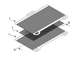
- FIG. 1 is an exploded perspective view of the power generation unit according to the first embodiment.
- FIG. 2 is an exploded perspective view of a portion where the power generation units of FIG. 1 are stacked.
- 3A is a cross-sectional view of the power generation units of FIG. 1 in a stacked state;
- FIG. 3B is a cross-sectional view of another example in which the power generation units of FIG. 1 are stacked.
- FIG. 4 is a diagram showing the relationship between bonding strength and bonding temperature for each bonding member.
- FIG. 5 is an enlarged view of the weld.
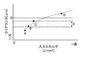
- FIG. 6 is a diagram showing the relationship between the input energy during welding and the clearance from the tip of the welded portion to the electrode.
- FIG. 7 is an exploded perspective view of a power generation unit according to a modification.
- FIG. 8 is an exploded perspective view of a portion where the power generation units of FIG. 7 are stacked.
- FIG. 9A is a cross-sectional view of a junction between an interconnector and an anode support layer according to a modification.
- FIG. 9B is an enlarged view of area A in FIG. 9A.
- FIG. 9C is an enlarged view of area B in FIG. 9A.
- FIG. 10 is a cross-sectional view of a stacked power generation unit according to the second embodiment.
- FIG. 1 is an exploded perspective view of a power generation unit 1 constituting a power generation module of a solid oxide fuel cell (hereinafter also simply referred to as "fuel cell”) according to this embodiment.
- the power generation unit 1 consists of a power generation cell 2, a cell frame 3 that supports the outer edge of the power generation cell 2, and an interconnector 4 that is welded to the active area 2A of the power generation cell 2 and the cell frame 3.
- laser welding is used as a welding method in this embodiment, it is not limited to this.
- the power generation cell 2 includes a membrane electrode assembly 2C in which an anode electrode is formed on one surface of a solid electrolyte plate and a cathode electrode is formed on the other surface, a cathode support layer 2B that supports the cathode electrode, and an anode that supports the anode electrode. and a support layer 2D. Both the cathode support layer 2B and the anode support layer 2D are made of metal such as ferritic stainless steel.
- the interconnector 4 is made of ferritic stainless steel containing aluminum (hereinafter also referred to as an Al-containing FSS), and the portion facing the active area 2A of the power generating cell 2 is processed so that the cross-sectional shape thereof is wavy. .
- this wavy portion is referred to as a wavy portion 4A.
- the interconnector 4 is welded to the power generation cell 2 at peaks of the wavy portion 4A and welded to the cell frame 3 at its outer edge.
- the welded portion between the waved portion 4A and the power generating cell 2 is as shown by the weld line 5 in FIG.
- the weld between the outer edge and the cell frame 3 surrounds all the weld lines 5 as indicated by the outer perimeter weld lines 6 in FIG.
- FIG. 2 is an exploded perspective view of a portion where two power generation units 1 are stacked.
- the two power generation units 1 are metal-bonded by a method other than welding, such as diffusion bonding or brazing using a metal bonding member 7, so that the interconnector 4 of one power generation unit 1 is connected to the power generation cell 2 of the other power generation unit 1. It is layered by being That is, the interconnector 4 has a function of electrically connecting the adjacent anode electrode and cathode electrode. Similarly, when stacking more power generation units 1, the power generation units 1 are metal-bonded by diffusion bonding or the like. The reason why welding is not used as a method for joining the power generating units 1 is that a welder cannot access the contact portion between the interconnector 4 and the power generating cell 2 when the power generating units 1 are in contact with each other.
- FIG. 3A is a diagram schematically showing a cross section along line III-III in FIG.
- the number of crests and troughs of the corrugated portion 4A is reduced compared to FIGS. 1 and 2 for the sake of simplicity.
- the power generation unit 1 is formed by welding the interconnector 4 to the cathode support layer 2B of the power generation cell 2 and the cell frame 3 .
- the ridges of the interconnector 4 are welded to the cathode support layer 2B. Thereby, a space surrounded by one surface of the interconnector 4 and the cathode support layer 2B is formed. This space is used as a cathode channel 8 as a first reactant gas channel.
- the valley portion of the interconnector 4 is metal-bonded to the anode support layer 2D of the other power generation unit 1 by diffusion bonding using the bonding member 7, brazing, or the like. Thereby, a space surrounded by the other surface of the interconnector 4 and the anode support layer 2D is formed. This space is used as an anode channel 9 as a second reactant gas channel.
- the interconnector 4 also functions as a partition plate that separates the cathode channel 8 and the anode channel 9 .
- FIG. 3B is a diagram schematically showing another example of a cross section along line III-III in FIG.
- the differences from FIG. 3A are the positions of the cathode support layer 2B and the anode support layer 2D with respect to the membrane electrode assembly 2C, and the valley of the interconnector 4 being welded to the cathode support layer 2B. Due to these differences, the portion corresponding to the outer peripheral weld line 6 in FIG. 3A is not welded but metal-bonded by diffusion bonding or brazing using the bonding member 7 . Also, the positions of the anode channel 9 and the cathode channel 8 are opposite to those in FIG. 3A.
- welding is used for joining with one power generating cell 2, and a method other than welding, such as diffusion bonding or brazing using the joining member 7, is used for joining with the other power generating cell 2. use.
- the support layer of the power generation cell 2 and the interconnector 4 are directly connected. Therefore, the electric resistance can be greatly reduced compared to the joining using the joining member 7 .
- the electrical connection is made directly as described above, the electrical connection can be ensured even if an oxide layer is formed on the surface of the interconnector 4 due to aging of the fuel cell.
- the electrical resistance of the joint is sensitive to temperature, so the electrical resistance fluctuates depending on the operating conditions of the fuel cell. does not occur.
- the temperature of the fuel cell increases during operation, and the surface of the interconnector 4 forming the cathode flow path 8 (also called the surface on the cathode side) is exposed to air. Therefore, the surface of the interconnector 4 on the cathode side is likely to be oxidized by oxygen in the air.
- the surface of the interconnector 4 forming the anode flow path (also referred to as the anode side surface) is exposed to hydrogen as the fuel gas, and is easily oxidized by water vapor. Corrosion of the interconnector 4 progresses due to these oxidations.
- hydrogen has the property of diffusing inside the interconnector 4 made of FSS.
- the diffused hydrogen moves from the interface on the anode side to the interface on the cathode side within the interconnector 4, it combines with the air flowing through the cathode channel 8 to generate water, which causes corrosion (this is called dual corrosion). ). Dual corrosion is particularly likely to occur in the case of the interconnector 4 formed thin by press molding or the like.
- corrosion may occur due to transpiration of chromium contained in FSS for corrosion resistance under high temperature conditions.
- the interconnector 4 As a measure to suppress the above corrosion, it is conceivable to form the interconnector 4 with FSS having an alumina layer on the surface. This is intended to suppress oxidation, diffusion of hydrogen, etc. by providing an alumina layer. However, FSS with an alumina layer on its surface cannot be welded.
- the interconnector 4 is formed of AL-containing FSS.
- Al-containing FSS can be welded because there is almost no alumina on the surface in the initial state.
- An alumina layer is formed on the anode-side surface during the stacking operation of the power generating unit 1 or during the operation of the fuel cell.
- diffusion of hydrogen into the interconnector 4 can be prevented, and corrosion caused by hydrogen moving to the cathode-side surface layer of the interconnector 4 can be suppressed.
- the Al-containing FSS the formation of oxides on the joint surface is suppressed, so durability can be ensured.
- the thickness of the alumina layer on the surface of the AL-containing FSS is about 50 nm or less, it can be said to be "almost absent".
- the joining member 7 is made of metal as described above. And it is desirable to include at least one of nickel and copper. The reason is as follows.
- the joining member 7 is used for joining the anode support layer 2D and the interconnector 4, so it is exposed to the fuel gas (hydrogen) flowing through the anode channel 9.
- nickel and copper have the property of being less likely to form aluminum oxide in a hydrogen atmosphere. Therefore, if the joining member 7 contains nickel or copper, it is possible to suppress the formation of aluminum oxide due to aluminum and oxygen contained in the anode support layer 2D and the interconnector 4 . As a result, an increase in electrical resistance can be suppressed, including during operation of the fuel cell.
- the particle size of the joining member 7 before joining is small. This is for the following reasons.
- the temporarily assembled fuel cell stack in which the plurality of power generation units 1 are stacked via the joining member 7 is placed in an electric furnace or the like. Then, the temperature is raised to melt the bonding member 7 .
- metals have the property that the higher the temperature, the more accelerated the oxidation.
- the bonding member 7 has a characteristic of melting at a lower temperature as the particle diameter becomes smaller. Therefore, the smaller the particle size of the joining member 7, the lower the temperature when forming the fuel cell stack, and the more the metal parts can be prevented from being oxidized.
- FIG. 4 is a diagram showing experimental results of investigating the relationship between temperature (also referred to as bonding temperature) and bonding strength when forming a fuel cell stack when the bonding member 7 contains nickel. Circles in the drawing indicate the case where the bonding member 7 is foil-shaped, triangles indicate the case of nanoparticles (particle size: 70 to 100 nm), and squares indicate the case of nanoparticles (particle size: 150 nm).
- a high bonding strength means that the interconnector 4 and the anode support layer 2D are firmly bonded. That is, it is considered that the higher the joint strength, the lower the electrical resistance of the joint between the interconnector 4 and the anode support layer 2D. Therefore, the threshold value of the bonding strength at which the electrical resistance that satisfies the performance of the fuel cell is obtained is defined as the threshold value S1.
- the higher the bonding temperature the higher the bonding strength.
- metal parts tend to oxidize at higher temperatures. In other words, if the bonding temperature is excessively high, although the bonding strength increases, oxidation of the metal parts is accelerated during the bonding operation.
- target operating temperature also referred to as target operating temperature
- the target operating temperature is, for example, about 600-650.degree. That is, if the bonding temperature is higher than the target operating temperature, the oxidation will be promoted by the bonding operation at a high temperature that will not be reached during operation after the fuel cell is completed. Therefore, the upper limit of the target operating temperature is set to the junction temperature threshold value T1.
- the bonding strength threshold S1 and bonding temperature threshold T1 the experimental results are examined.
- the bonding strength does not reach the threshold S1 when the bonding temperature is equal to or lower than the threshold T1.
- the bonding strength reaches the threshold S1 even when the bonding temperature is equal to or lower than the threshold T1. Therefore, it is desirable that the grain size before bonding of the bonding member 7 is 150 nm or less.
- Fig. 5 is an enlarged view of the joint.
- the weld line 5 is formed by melting the interconnector 4 and the cathode support layer 2B.
- a clearance L is defined as a distance from the tip of the welding line 5 in the thickness direction to the membrane electrode assembly 2C (that is, to the cathode electrode).
- FIG. 6 is a diagram showing the relationship between input energy and clearance L for welding. As the input energy increases, the melting region expands, and the clearance L becomes smaller as shown in FIG. The smaller the clearance L, the higher the joint strength, but the larger the amount of heat transferred to the cathode electrode during welding. For example, as shown in D in FIG. 6, if the weld line 5 reaches the cathode electrode, the cathode electrode will deteriorate due to heat. Also, if the clearance L is not sufficient, the cathode electrode may deteriorate due to heat. On the other hand, if the clearance L is excessively large as shown in FIG. 6A, the joint strength is insufficient.
- the input energy is controlled so that the clearance L falls within the range (E in FIG. 6) in which the cathode electrode is not thermally deteriorated and sufficient bonding strength is obtained.
- the lower limit of range E is, for example, about 50 ⁇ m, and the upper limit varies depending on the thickness of the cathode support layer.
- the power generation cell 2 having the solid electrolyte plate, the anode electrode arranged on one surface of the solid electrolyte plate, and the cathode electrode arranged on the other surface of the solid electrolyte plate has a cathode electrode.
- a fuel cell is provided in which a plurality of fuel cells are stacked in the thickness direction via an interconnector 4 that electrically connects the electrodes and the anode electrode.
- the anode electrode and the cathode electrode have support layers 2B and 2D made of metal, and either the support layer 2D of the anode electrode or the support layer 2B of the cathode electrode and the interconnector 4 are welded.
- the other of the anode electrode support layer 2D and the cathode electrode support layer 2B is joined to the interconnector 4 by a method other than welding. According to this, it is possible to join and stack a plurality of power generation units 1, and electrical resistance can be reduced by providing a joining portion by welding.
- the support layer 2B of the cathode electrode and the interconnector 4 are joined by welding, and the support layer 2D of the anode electrode and the interconnector 4 are metal-joined by a method other than welding.
- the electrical resistance between the cathode electrode and the interconnector 4 can be reduced.
- the welded joint welding line 5 can ensure continuity.
- the interconnector 4 of this embodiment is composed of AL-containing FSS.
- Al-containing FSS can be welded because there is almost no alumina on the surface in the initial state.
- diffusion of hydrogen into the interconnector 4 is prevented, and corrosion due to hydrogen diffusion is prevented. can be suppressed.
- the Al-containing FSS the formation of oxides on the joint surface is suppressed, so durability can be ensured.
- diffusion bonding using the bonding member 7 or brazing is used as a method other than welding.
- the strength of the joint is ensured, so that the joint state can be maintained even if there are fluctuations in temperature and load during power generation of the fuel cell. In other words, a conductive state can be ensured.
- the upper limit of the grain size of the bonding member 7 before bonding is limited to a size that allows a predetermined bonding strength to be obtained when bonding at a temperature at which the cathode support layer 2B is not oxidized. As a result, the temperature during the joining operation can be suppressed, and oxidation of the metal parts can be suppressed.
- the anode support layer 2D and the interconnector 4 are joined using a metallic joint member 7, and the joint member 7 contains at least one of nickel and copper.
- Nickel and copper have the property of being less likely to form aluminum oxide in a hydrogen atmosphere. Therefore, according to this embodiment, the formation of aluminum oxide by aluminum and oxygen contained in the anode support layer 2D and the interconnector 4 can be suppressed. . As a result, an increase in electrical resistance can be suppressed, including during operation of the fuel cell.
- anode support layer 2D and the interconnector 4 are joined by diffusion bonding or brazing, but in this modified example they are joined by so-called electrical connection.
- Electric joining is a technology that joins metals by using resistance heat generated by passing electricity through metal parts.
- FIG. 7 is an exploded perspective view of the power generation unit 1 according to this modified example.
- FIG. 8 is an exploded perspective view of a portion where two power generation units 1 are stacked.
- a substantial difference between FIGS. 7 and 8 and FIGS. 1 and 2 is that a current-carrying tab 10 is welded to one end of the power generation cell 2 .
- Reference numeral 11 in FIGS. 7 and 8 denotes a welding line when the current-carrying tab 10 is welded to the power generation cell 2.
- reference numeral 12 in FIG. 8 indicates a joint portion (also referred to as an electric joint portion) when joined by electric joining. Note that the number of conductive joints 12 and the spacing between adjacent conductive joints 12 are different from the actual product. The interval between adjacent conductive joints 12 will be described later.
- the joining portion can be selectively heated. Therefore, according to the electrical connection, it is possible to metal-bond the interconnector 4 and the anode support layer 2D to reduce the electrical resistance while suppressing the oxidation of the metal parts during the fuel cell stack forming operation.
- FIG. 9A is a cross-sectional view of the joint between the interconnector 4 and the anode support layer 2D in this modification.
- 9B is an enlarged view of area A in FIG. 9A
- FIG. 9C is an enlarged view of area B in FIG. 9A.
- the end portion on the side opposite to the region A is also the same as in FIG. 9B.
- a plurality of current-carrying joints 12 are arranged in parallel in the width direction of the current-carrying joints 12 .
- the widthwise dimension (W2 in FIG. 9C) of the electrically conductive junction 12 at the center in the widthwise direction is larger than the widthwise dimension (W1 in FIG. 9B) of the electrically conductive junctions 12 at both ends in the widthwise direction.
- the electrical resistance of the conductive joints 12 located in the center in the width direction is smaller than that of the conductive joints 12 located at both ends in the width direction.
- the center in the width direction has a higher temperature than the ends, and the generated current density also increases. Therefore, according to this modified example, the electric resistance of the current-carrying joint 12 is smaller in the portion where the generated current density is higher. resistance can be reduced.
- the method other than welding in this modified example is energization joining that joins the contact portion between the interconnector 4 and the anode support layer 2D by energizing the interconnector 4 and the anode support layer 2D.
- the power generation unit 1 as a whole can be joined without raising the temperature, so that the effect of reducing electrical resistance by metal joining can be obtained while suppressing oxidation of the metal parts.
- a plurality of joints (current-carrying joints 12) formed by a method other than welding are arranged in parallel in the width direction of the current-carrying joints 12, and are positioned more centrally in the width direction than the current-carrying joints 12 at both ends in the width direction.
- the conductive joint 12 has a larger width dimension.
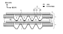
- FIG. 10 is a cross-sectional view showing a cross-section of a portion where two power generation units 1 are stacked, like FIG. 3 of the first embodiment.
- the difference from FIG. 3 is that the power generating units 1 in which the interconnector 4 is welded to the anode support layer 2D and the cell frame 3 are joined via the joining member 7.
- FIG. 10 As a result, the space surrounded by one surface of the interconnector 4 and the anode support layer 2D is surrounded by the anode flow channel 9 as the first reaction gas flow channel and the other surface of the interconnector 4 and the cathode support layer 2B.
- the enclosed space becomes the cathode channel 8 as the second reactant gas channel.
- the electrical resistance between the interconnector 4 and the anode electrode is greatly reduced.
- the collector resistance on the anode side can be significantly reduced.
- the interconnector 4 is welded to the anode support layer 2D and also to the cell frame 3 at the same time.
- the weld line with the cell frame 3 surrounds all the anode flow channels 9 in the same manner as the outer peripheral weld line 6 in FIG. That is, the sealing of the anode channel 9 is completed at the stage of producing the power generation unit 1 .
- the joint member 7 is exposed to oxygen flowing through the cathode flow channel 8 . Therefore, the joining member 7 is oxidized over time. Therefore, in the present embodiment, the joining member 7 containing an element (for example, chromium, manganese) that ensures conductivity even when it becomes an oxide and has a property of being easily joined as an aluminate to aluminum in the adjacent interconnector 4.
- an element for example, chromium, manganese
- Use Elements other than chromium and manganese may be used as long as they have the properties described above.
- the cell frame 3 that supports the outer edge of the power generation cell 2 is provided, and the interconnector 4 is welded to the anode electrode support layer (anode support layer 2D) and the cell frame 3, and the cathode electrode
- the supporting layer (cathode supporting layer 2B) and the interconnector 4 are metal-bonded by a method other than welding.
- the collector resistance on the anode side can be reduced.
- the sealing of the anode channel 9 is completed at the stage of producing the power generation unit 1 .
- the cathode support layer 2B and the interconnector 4 are joined using a metal joining member 7, and the joining member 7 contains at least one of cobalt and manganese.
- the cathode support layer 2B and the interconnector 4 can be firmly joined together, and even if the joining member 7 is oxidized over time, the continuity can be ensured.
Landscapes
- Engineering & Computer Science (AREA)
- Manufacturing & Machinery (AREA)
- Chemical & Material Sciences (AREA)
- Life Sciences & Earth Sciences (AREA)
- Sustainable Development (AREA)
- Sustainable Energy (AREA)
- Chemical Kinetics & Catalysis (AREA)
- Electrochemistry (AREA)
- General Chemical & Material Sciences (AREA)
- Inorganic Chemistry (AREA)
- Fuel Cell (AREA)
Abstract
Priority Applications (5)
| Application Number | Priority Date | Filing Date | Title |
|---|---|---|---|
| JP2022505462A JP7294522B2 (ja) | 2021-04-15 | 2021-04-15 | 燃料電池および燃料電池の製造方法 |
| PCT/JP2021/015642 WO2022219791A1 (fr) | 2021-04-15 | 2021-04-15 | Pile à combustible et procédé de fabrication de pile à combustible |
| US17/631,973 US20240039010A1 (en) | 2021-04-15 | 2021-04-15 | Fuel cell and manufacturing method of fuel cell |
| EP21839811.3A EP4325606A1 (fr) | 2021-04-15 | 2021-04-15 | Pile à combustible et procédé de fabrication de pile à combustible |
| CN202180005185.3A CN115485888A (zh) | 2021-04-15 | 2021-04-15 | 燃料电池及燃料电池的制造方法 |
Applications Claiming Priority (1)
| Application Number | Priority Date | Filing Date | Title |
|---|---|---|---|
| PCT/JP2021/015642 WO2022219791A1 (fr) | 2021-04-15 | 2021-04-15 | Pile à combustible et procédé de fabrication de pile à combustible |
Publications (1)
| Publication Number | Publication Date |
|---|---|
| WO2022219791A1 true WO2022219791A1 (fr) | 2022-10-20 |
Family
ID=83640275
Family Applications (1)
| Application Number | Title | Priority Date | Filing Date |
|---|---|---|---|
| PCT/JP2021/015642 WO2022219791A1 (fr) | 2021-04-15 | 2021-04-15 | Pile à combustible et procédé de fabrication de pile à combustible |
Country Status (5)
| Country | Link |
|---|---|
| US (1) | US20240039010A1 (fr) |
| EP (1) | EP4325606A1 (fr) |
| JP (1) | JP7294522B2 (fr) |
| CN (1) | CN115485888A (fr) |
| WO (1) | WO2022219791A1 (fr) |
Citations (8)
| Publication number | Priority date | Publication date | Assignee | Title |
|---|---|---|---|---|
| JP2006236989A (ja) | 2005-01-25 | 2006-09-07 | Sumitomo Precision Prod Co Ltd | 燃料電池用単電池セル |
| JP2009212046A (ja) * | 2008-03-06 | 2009-09-17 | Nissan Motor Co Ltd | 固体酸化物形燃料電池用金属部材 |
| JP2010140656A (ja) * | 2008-12-09 | 2010-06-24 | Nissan Motor Co Ltd | 燃料電池用集電体及び固体電解質型燃料電池 |
| JP2010157387A (ja) * | 2008-12-26 | 2010-07-15 | Nissan Motor Co Ltd | 固体電解質形燃料電池用インターコネクタ |
| JP2012190725A (ja) * | 2011-03-11 | 2012-10-04 | Ngk Spark Plug Co Ltd | 固体酸化物形燃料電池 |
| WO2016189620A1 (fr) * | 2015-05-25 | 2016-12-01 | 日産自動車株式会社 | Pile à combustible à oxyde solide |
| WO2017175371A1 (fr) * | 2016-04-08 | 2017-10-12 | 日産自動車株式会社 | Pile unitaire de pile à combustible |
| JP2019036443A (ja) * | 2017-08-10 | 2019-03-07 | 日産自動車株式会社 | 燃料電池スタックのセル構造および燃料電池セルのたわみ規制方法 |
-
2021
- 2021-04-15 US US17/631,973 patent/US20240039010A1/en active Pending
- 2021-04-15 CN CN202180005185.3A patent/CN115485888A/zh active Pending
- 2021-04-15 EP EP21839811.3A patent/EP4325606A1/fr active Pending
- 2021-04-15 WO PCT/JP2021/015642 patent/WO2022219791A1/fr active Application Filing
- 2021-04-15 JP JP2022505462A patent/JP7294522B2/ja active Active
Patent Citations (8)
| Publication number | Priority date | Publication date | Assignee | Title |
|---|---|---|---|---|
| JP2006236989A (ja) | 2005-01-25 | 2006-09-07 | Sumitomo Precision Prod Co Ltd | 燃料電池用単電池セル |
| JP2009212046A (ja) * | 2008-03-06 | 2009-09-17 | Nissan Motor Co Ltd | 固体酸化物形燃料電池用金属部材 |
| JP2010140656A (ja) * | 2008-12-09 | 2010-06-24 | Nissan Motor Co Ltd | 燃料電池用集電体及び固体電解質型燃料電池 |
| JP2010157387A (ja) * | 2008-12-26 | 2010-07-15 | Nissan Motor Co Ltd | 固体電解質形燃料電池用インターコネクタ |
| JP2012190725A (ja) * | 2011-03-11 | 2012-10-04 | Ngk Spark Plug Co Ltd | 固体酸化物形燃料電池 |
| WO2016189620A1 (fr) * | 2015-05-25 | 2016-12-01 | 日産自動車株式会社 | Pile à combustible à oxyde solide |
| WO2017175371A1 (fr) * | 2016-04-08 | 2017-10-12 | 日産自動車株式会社 | Pile unitaire de pile à combustible |
| JP2019036443A (ja) * | 2017-08-10 | 2019-03-07 | 日産自動車株式会社 | 燃料電池スタックのセル構造および燃料電池セルのたわみ規制方法 |
Also Published As
| Publication number | Publication date |
|---|---|
| JP7294522B2 (ja) | 2023-06-20 |
| US20240039010A1 (en) | 2024-02-01 |
| JPWO2022219791A1 (fr) | 2022-10-20 |
| CN115485888A (zh) | 2022-12-16 |
| EP4325606A1 (fr) | 2024-02-21 |
Similar Documents
| Publication | Publication Date | Title |
|---|---|---|
| JP5076360B2 (ja) | 燃料電池スタック並びにその製造方法 | |
| JP5383051B2 (ja) | 燃料電池及び燃料電池スタック | |
| US9893370B2 (en) | Single fuel cell, fuel cell stack, and method of manufacturing fuel cell stack | |
| JP5093833B2 (ja) | 燃料電池用単電池セル | |
| JP5679893B2 (ja) | 固体酸化物形燃料電池及びその製造方法 | |
| JP5076359B2 (ja) | 燃料電池スタックおよび燃料電池セパレータ並びにその製造方法 | |
| JP4438295B2 (ja) | 燃料電池 | |
| JP6131426B2 (ja) | 燃料電池のシール構造 | |
| JP4666279B2 (ja) | 固体酸化物形燃料電池スタック及び固体酸化物形燃料電池 | |
| JP4123479B2 (ja) | 燃料電池用単セル、その製造方法及び固体酸化物形燃料電池 | |
| JP4900364B2 (ja) | 燃料電池 | |
| JP5578200B2 (ja) | 燃料電池スタック並びにその製造方法 | |
| JP7294522B2 (ja) | 燃料電池および燃料電池の製造方法 | |
| JP5017857B2 (ja) | 燃料電池用のセパレータおよび固体酸化物形燃料電池 | |
| JP2004281353A (ja) | 燃料電池用セパレータ | |
| JP2019192363A (ja) | セルユニットおよびメタルサポートセルの補強方法 | |
| US8557467B2 (en) | Fuel cell and fuel cell stack | |
| JP4984374B2 (ja) | 燃料電池 | |
| JP4470474B2 (ja) | 固体電解質型燃料電池 | |
| JP4073750B2 (ja) | 拡散層セパレータ接合体の製造方法 | |
| JP6805203B2 (ja) | 電気化学反応単位および電気化学反応セルスタック | |
| CN113451606A (zh) | 接合结构及燃料电池用隔膜 | |
| WO2023119602A1 (fr) | Pile à combustible à oxyde solide | |
| WO2023119603A1 (fr) | Batterie à combustible à oxyde solide | |
| WO2022259372A1 (fr) | Pile à combustible à oxyde solide et procédé de production d'une pile à combustible à oxyde solide |
Legal Events
| Date | Code | Title | Description |
|---|---|---|---|
| ENP | Entry into the national phase |
Ref document number: 2022505462 Country of ref document: JP Kind code of ref document: A |
|
| WWE | Wipo information: entry into national phase |
Ref document number: 17631973 Country of ref document: US |
|
| 121 | Ep: the epo has been informed by wipo that ep was designated in this application |
Ref document number: 21839811 Country of ref document: EP Kind code of ref document: A1 |
|
| WWE | Wipo information: entry into national phase |
Ref document number: 2021839811 Country of ref document: EP |
|
| NENP | Non-entry into the national phase |
Ref country code: DE |
|
| ENP | Entry into the national phase |
Ref document number: 2021839811 Country of ref document: EP Effective date: 20231115 |