WO2022215643A1 - 止水装置 - Google Patents
止水装置 Download PDFInfo
- Publication number
- WO2022215643A1 WO2022215643A1 PCT/JP2022/016477 JP2022016477W WO2022215643A1 WO 2022215643 A1 WO2022215643 A1 WO 2022215643A1 JP 2022016477 W JP2022016477 W JP 2022016477W WO 2022215643 A1 WO2022215643 A1 WO 2022215643A1
- Authority
- WO
- WIPO (PCT)
- Prior art keywords
- water stop
- installation
- stop device
- water
- installation member
- Prior art date
- Legal status (The legal status is an assumption and is not a legal conclusion. Google has not performed a legal analysis and makes no representation as to the accuracy of the status listed.)
- Ceased
Links
Images






Classifications
-
- E—FIXED CONSTRUCTIONS
- E02—HYDRAULIC ENGINEERING; FOUNDATIONS; SOIL SHIFTING
- E02B—HYDRAULIC ENGINEERING
- E02B7/00—Barrages or weirs; Layout, construction, methods of, or devices for, making same
- E02B7/20—Movable barrages; Lock or dry-dock gates
- E02B7/22—Stop log dams; Emergency gates
-
- E—FIXED CONSTRUCTIONS
- E04—BUILDING
- E04H—BUILDINGS OR LIKE STRUCTURES FOR PARTICULAR PURPOSES; SWIMMING OR SPLASH BATHS OR POOLS; MASTS; FENCING; TENTS OR CANOPIES, IN GENERAL
- E04H9/00—Buildings, groups of buildings or shelters adapted to withstand or provide protection against abnormal external influences, e.g. war-like action, earthquake or extreme climate
- E04H9/14—Buildings, groups of buildings or shelters adapted to withstand or provide protection against abnormal external influences, e.g. war-like action, earthquake or extreme climate against other dangerous influences, e.g. tornadoes, floods
-
- E—FIXED CONSTRUCTIONS
- E06—DOORS, WINDOWS, SHUTTERS, OR ROLLER BLINDS IN GENERAL; LADDERS
- E06B—FIXED OR MOVABLE CLOSURES FOR OPENINGS IN BUILDINGS, VEHICLES, FENCES OR LIKE ENCLOSURES IN GENERAL, e.g. DOORS, WINDOWS, BLINDS, GATES
- E06B5/00—Doors, windows, or like closures for special purposes; Border constructions therefor
Definitions
- the present invention relates to, for example, a water stoppage device for taking countermeasures against flooding when flood damage occurs.
- Various flood prevention equipment has been proposed as a method to prevent flooding of buildings in the event of flood damage. For example, there is a method of providing an opening/closing type or sliding type waterproof shutter or waterproof door at the entrance of a building, and closing the shutter or door when necessary.
- Such waterproof equipment is installed integrally with the building. For this reason, the equipment is large-scale and can only be used in specific locations.
- Patent Document 1 As a method with better installation work, a method of stopping water using a substantially L-shaped water stop plate has been proposed (for example, Patent Document 1).
- Patent Document 1 by connecting L-shaped integrated panels with a connecting frame, it is possible to stop water in a predetermined range.
- Patent Document 1 since the waterproof member of Patent Document 1 is substantially L-shaped, there is a problem that it is bulky during transportation and storage.
- Patent Document 2 a foldable substantially L-shaped waterproof device has been proposed (Patent Document 2). According to the water stop device of Patent Document 2, it can be in a folded state during transportation and storage, so it does not take up much space.
- JP 2016-223183 A Japanese Patent No. 6748317
- Patent Document 1 since a plurality of water stop devices are only connected by a clip-shaped connecting member, the strength of the connecting portion is weak, and it is difficult to ensure the water stopping of the connecting portion. is. In addition, since it is necessary to connect the adjacent water stop plates with clips, which are separate members, after installing them, the number of parts is large and workability is poor.
- the present invention has been made in view of such problems, and an object of the present invention is to obtain a water stop device with good installation workability and water stop performance.
- the present invention provides a water shutoff device that can be used to prevent flooding, comprising: an installation member installed on an installation surface; a member, wherein a first installation member connection portion is provided on one end side of the installation member, and a second installation member connection portion is provided on the other end side of the installation member; A first erecting member connecting portion is provided at one end of the erecting member, a second erecting member connecting portion is provided at the other end of the erecting member, and the second installation member connecting portion is provided.
- the water stop device is characterized in that it can be connected to the first upright member connecting portion in the opening direction of the upright member.
- a hinge part waterproof member is arranged behind the hinge part, and in a state in which the standing member is erected with respect to the installation member, the hinge part waterproof member is sandwiched between the installation member and the standing member. is desirable.
- connection portion between the first installation member connection portion and the second installation member connection portion and the connection portion between the first upright member connection portion and the second upright member connection portion are provided with a connection portion waterproofing
- a member is preferably arranged.
- the first installation member connection portion and the second installation member connection portion can be connected by engaging each other's grooves and claws, and the first upright member connection portion and the second upright member connection portion are:
- the grooves and claws are engaged with each other to enable connection, and in each connection, a clearance is formed between the grooves and the claws, and the connection length and the connection angle in the connection direction are determined. It may be adjustable.
- An anti-slip member is arranged on the lower surface side of the installation member, and a protrusion is provided on the outer surface side of the standing member at a position that avoids a portion corresponding to the anti-slip member when the water stop device is folded and stacked. part may be formed.
- the length of the installation member is longer than the length of the upright member, and a water stop member is arranged on the lower surface side near the front end of the installation member. Assuming that the protruding length of the front end portion of the installation member from the front end of the member is L2, L1 ⁇ L2 may be
- a water storage part may be provided on the upper surface of the installation member, and water may be stored.
- the water storage part may be in the shape of a masu or a tank.
- the installation member and the standing member can be opened and closed via the hinge portion, it can be in a folded state during transportation or storage, and can be opened into a substantially L shape when the standing member is opened during use.
- Adjacent water stop devices can be connected to each other for each of the installation member and the standing member.
- connection portions can be connected from above, when installing a new water stoppage device next to an existing water stoppage device, the connection portions can be connected by simply placing the installation member from above. can do.
- the erecting member connecting portion can be connected in the opening direction of the erecting members, the erecting members can be connected to each other simply by arranging the installation member and erecting the erecting members.
- the hinge portion waterproof member behind the hinge portion, it is possible to ensure water stopping properties between the installation member and the erecting member when the erecting member is erected with respect to the installation member.
- a groove and a claw are provided in the installation member connecting portion and the upright member connecting portion, respectively, and a clearance is formed between the groove and the claw, so that the connecting length and the connecting angle in the connecting direction can be adjusted. It is possible to adjust.
- the anti-slip member is arranged on the lower surface side of the installation member, and a convex portion is formed on the outer surface side of the standing member at a position avoiding the portion corresponding to the anti-slip member when the water stop device is folded and stacked. Therefore, when the water stop devices are stacked, the anti-slip member can be prevented from coming into contact with the standing members of the stacked water stop devices and being damaged.
- the water stop member when the water stop member is arranged on the lower surface side near the front end portion of the installation member, when the length of the water stop member is L1 and the protrusion length of the upright member to the front end side of the installation member is L2. , L1 ⁇ L2, when the water stop devices are stacked, it is possible to prevent the water stop members from coming into contact with the standing members of the water stop devices that are stacked and being damaged.
- Such a water storage part may be in the shape of a square or a tank.
- FIG. 1 The perspective view which shows the water stop device 1 of the closed state.
- FIG. FIG. 2 is a side view of the water stop device 1 in a closed state;
- FIG. 4B is an enlarged view of the vicinity of the hinge portion 7 in FIG. 4A;
- FIG. 2 is a side view of the water stop device 1 in an open state;
- FIG. 5B is an enlarged view of the vicinity of the hinge portion 7 in FIG. 5A;
- FIG. 2 is a plan view of the water stop device 1 in a state where water is stored; EE line sectional view of FIG. 6A.
- FIG. Fig. 4 is a side view showing a state in which the water stop devices 1 are stacked; NN line sectional view of FIG. 9A.
- FIG. 1 is a perspective view showing a water stop device 1 in a closed state
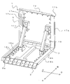
- FIG. 2 is a perspective view of the water stop device 1 in an open state.
- the water stop device 1 is a member that can be used to prevent water intrusion, and can be folded as shown in FIG. 1 during storage and transportation, and opened as shown in FIG. 2 when used.
- the water stop device 1 is mainly composed of an installation member 3 that is installed on an installation surface such as the ground, and an upright member 5 that can be opened and closed with respect to the installation member 3 via a hinge portion 7 (see FIG. 2).
- the side on which the standing member 5 is opened (direction A in the drawing) is the front of the water stop device
- the hinge portion 7 side (direction B in the drawing) is the rear of the water stop device 1 .
- the direction orthogonal to the front-back direction of the water stop device 1 (the direction of C and D in the drawing) be the width direction of the water stop device 1 .
- An installation member connection portion 9a which is a first installation member connection portion, is provided on one end side of the installation member 3 in the width direction (the end portion side in the C direction in the drawing).
- a second installation member connecting portion 9b is provided on the other end side of the installation member 3 in the width direction (end portion side in the D direction in the figure).
- An upright member connection portion 11a (see FIG. 2), which is a first upright member connection portion, is provided on one end side of the upright member 5 in the width direction (the end side in the direction C in the figure).
- An upright member connecting portion 11b which is a second upright member connecting portion, is provided on the other end portion side in the width direction of the upright member 5 (the end portion side in the D direction in the drawing).
- the installation member 3 and the standing member 5 can be maintained in a substantially L-shaped state by a pair of stoppers 19 .
- the stopper 19 can be accommodated inside the installation member 3 and the standing member 5 when the standing member 5 is folded. Note that the arrangement and number of stoppers 19 are not limited to the illustrated example.
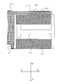
- FIG. 3 is a diagram showing the lower surface of the installation member 3.
- a lower surface waterproof member 23 is arranged on the front end side of the installation member 3 .
- the lower water cutoff member 23 is made of a compressively deformable member such as rubber.
- the lower water cutoff member 23 is arranged over the entire width of the installation member 3 .
- notches are partially formed at the widthwise end portions of the lower water-stopping members 23 so that the lower water-stopping members 23 of the adjacent water-stopping devices 1 are engaged with each other.
- the lower surface water cutoff member 23 is composed of a compressively deformable member such as rubber.
- a drainage groove 25 is provided behind the lower water stop member 23 of the installation member 3 .
- the drainage groove 25 is substantially in the center of the installation member 3 in the width direction, and continues from the rear of the lower surface waterproof member 23 to the rear end of the installation member 3 .
- the drainage groove 25 is a groove provided on the lower surface of the installation member 3 and is a portion for discharging water that has entered below the installation member 3 beyond the lower water stop member 23 to the rear of the water stop device 1 .
- Anti-slip members 27 are arranged on both sides of the drainage groove 25 behind the lower surface water stop member 23 of the installation member 3 .
- the anti-slip member 27 is a member for suppressing displacement and unintended movement of the water stop device 1 when the water stop device 1 is installed on an installation surface such as the ground.
- the anti-slip member 27 is made of a compressively deformable member such as rubber.
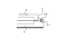
- FIG. 4A is a side view of the water stop device 1 in a closed state
- FIG. 4B is an enlarged view of the vicinity of the hinge portion 7 in FIG. 4A
- 5A is a side view of the water stop device 1 in an open state
- FIG. 5B is an enlarged view of the vicinity of the hinge portion 7 in FIG. 5A.
- the upright member 5 can be opened with respect to the installation member 3 via the hinge portion 7 .
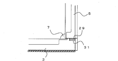
- a groove 31 is formed behind the hinge portion 7 , and the hinge portion waterproof member 29 is arranged in the groove 31 .
- the hinge portion waterproof member 29 is made of a compressively deformable member such as rubber.
- the installation member 3 and the erecting member 5 sandwich the hinge portion waterproof member 29.
- the rear end surface of the upright member 5 and the upper surface of the installation member 3 are in close contact with the hinge portion waterproof member 29 . Therefore, behind the hinge portion 7 , the gap between the installation member 3 and the standing member 5 can be water-stopped by the hinge-portion water-stopping member 29 .
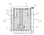
- FIG. 6A is a plan view showing a state in which the water stop device 1 is installed
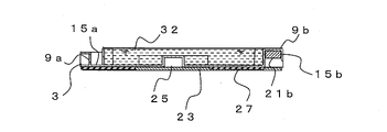
- FIG. 6B is a cross-sectional view taken along line EE of FIG. 6A.
- the installation member 3 has a side wall with an upright peripheral edge along the entire circumference. That is, the upper surface of the installation member 3 is square-shaped. Therefore, the upper surface of the installation member 3 serves as a water reservoir that can store the water 32 .
- the water reservoir formed on the upper surface of the installation member 3 may be tank-shaped instead of square-shaped.
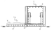
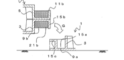
- FIG. 7A is a front view showing a state before the installation members 3 are connected
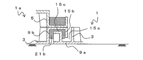
- FIG. 7B is a diagram showing a state where the installation members 3 are connected to each other.
- a new water stop device 1a is installed next to the existing water stop device 1, but the water stop device 1a is a water stop device 1 and completely the same configuration.
- the water stop device 1 is installed by placing the water stop device 1 on the ground, which is the installation surface, opening the upright member 5, and fixing it with a stopper.
- the water stop device 1a is installed to the existing water stop device 1.
- the water stop device 1a is arranged so as to be adjacent to the water stop device 1 with the standing member 5 folded.
- FIG. 8A is an enlarged cross-sectional view of the F portion in the state of FIG. 7A.
- the installation member connecting portion 9a is provided on one end portion side of the water stop device 1 (end portion on the left side in the figure).
- the installation member connecting portion 9a has a groove portion 15a that opens upward.
- the side wall portion on the outside of the groove portion 15a serves as a convex portion 15c that protrudes upward.
- an installation member connection portion 9b is provided on the other end portion side (end portion on the right side in the drawing) of the water stop device 1a.
- the installation member connecting portion 9b has a claw portion 15b protruding downward.
- a connecting portion waterproof member 21b exposed downward is provided inside the claw portion 15b.
- the connecting portion waterproof member 21b is made of a compressively deformable member such as rubber.
- FIG. 7B is a front view showing a state in which the installation members 3 are connected to each other
- FIG. 8B is an enlarged cross-sectional view of part H in FIG. 7B.
- the illustrated example shows an example in which the connecting portion water-stopping member 21b is greatly deformed, if the connecting portion water-stopping member 21b and the convex portion 15c can be brought into close contact with each other, the deformation of the connecting portion water-stopping member 21b is slight. good.
- the installation member connection portion 9b of the water stop device 1a can be connected downward to the installation member connection portion 9a of another adjacent water stop device 1. Therefore, the connection between the installation members 3 is completed only by arranging the water stop device 1a at a predetermined position next to the existing water stop device 1 . At this time, since the connection portion water cutoff member 21b is disposed at the connection portion between the installation member connection portion 9a and the installation member connection portion 9b, it is possible to secure water cutoff at the connection portion.
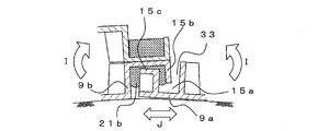
- the installation member connection portion 9a and the installation member connection portion 9b have the groove portion 15a and the claw portion 15b, and can be connected by engaging the groove portion 15a and the claw portion 15b with each other.
- a clearance 33 is formed between the groove portion 15a and the claw portion 15b. Therefore, the connection length (J in the figure) and the connection angle (I in the figure) of the water stop devices 1 and 1a in the connection direction can be adjusted. By doing so, it is possible to adjust the length of connection between the water stop devices, and to ensure water stoppage by reliably connecting the water stop devices even when the ground is not flat.
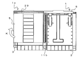
- FIG. 9A is a plan view of the water stop device 1a before the erecting member 5 is opened
- FIG. 9B is a plan view showing the erected state after the erecting member 5 is opened.
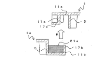
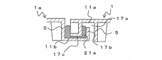
- FIG. 10A is an enlarged cross-sectional view showing the state before connection at the L portion in FIG. 9B
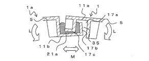
- FIG. 10B is an enlarged cross-sectional view showing the state after connection at the L portion in FIG. 9B.
- the upright member connecting portion 11a is provided on one end side (the left end portion in the drawing) of the water stop device 1 .
- the upright member connecting portion 11a has a groove portion 17a that is open to the front (lower surface side when closed) when erected. Further, the side wall portion of the groove portion 17a serves as a convex portion 17c that protrudes forward (lower surface side when closed).
- an upright member connecting portion 11b is provided on the other end portion side (end portion on the right side in the figure) of the water stop device 1a.
- the upright member connecting portion 11b has a claw portion 17b that protrudes rearward when erected (upper surface side when closed).
- a connecting portion waterproofing member 21a exposed in the projecting direction of the claw portion 17b is provided inside the claw portion 17b.
- the connecting portion waterproof member 21a is made of a compressively deformable member such as rubber.
- the claw portion 17b of the upright member connecting portion 11b of the water shutoff device 1a is inserted into the groove portion 17a of the upright member connecting portion 11a of the water shutoff device 1a.
- the convex portion 17c of the upright member connecting portion 11a is in close contact with the connecting portion waterproof member 21a of the upright member connecting portion 11b.
- the standing members 5 are connected to each other.
- the upright member connection portion 11b of the water stop device 1a can be connected to the upright member connection portion 11a of the other adjacent water stop device 1 in the opening direction of the upright member 5. .
- the water stop device 1a is arranged at a predetermined position next to the existing water stop device 1, the installation members 3 are connected to each other, and the standing members 5 can be installed by simply opening the upright members 5 of the water stop device 1a. connection is completed.
- the connecting portion water cutoff member 21a is arranged at the connecting portion between the rising member connecting portion 11a and the rising member connecting portion 11b, it is possible to secure water stopping at the connecting portion.
- the upright member connection portion 11a and the upright member connection portion 11b similarly to the connection portion between the installation members 3, the upright member connection portion 11a and the upright member connection portion 11b have groove portions 17a and claw portions 17b, and the groove portions 17a and claw portions 17b are engaged with each other. can be concatenated with At this time, as shown in FIG. 10C, a clearance 35 is formed between the groove portion 17a and the claw portion 17b. Therefore, it is possible to adjust the connection length (M in the figure) and the connection angle (L in the figure) of the water stop devices 1 and 1a in the connection direction. By doing so, it is possible to adjust the length of connection between the water stop devices, and to bend the water stop devices at a predetermined angle and connect them.
- the connecting portion waterproof member 21a is arranged in the installation member connecting portion 9b, but it may be provided on the installation member connecting portion 9a side.
- the connecting portion waterproof member 21a is disposed on the upright member connecting portion 11b, it may be provided on the upright member connecting portion 11a side.
- the installation member connecting portion 9a is provided with the groove portion 15a, and the installation member connection portion 9b is provided with the claw portion 15b. good too.
- the upright member connecting portion 11a is provided with the groove portion 17a, and the upright member connecting portion 11b is provided with the claw portion 17b.
- FIG. 11 is a conceptual diagram showing a water stop structure 30 formed by connecting a plurality of water stop devices.
- a plurality of water stop devices 1 By connecting a plurality of water stop devices 1 in the width direction (directions C and D in the figure) and forming them in a predetermined length, water from the front side (direction A in the drawings) of the water stop device 1 can be stopped. It can be dammed by the device 1 (upright member 5).
- the water pressure is applied to the front side of the standing member 5, the water pressure is also applied to the upper side of the installation member 3, so the water stop device 1 does not fall down.
- the water pressure from above the installation member 3 presses the lower water stop member 23 (see FIG. 3) against the ground, the lower water stop member 23 is in close contact with the ground, and the water flows out to the lower surface of the installation member 3. can be suppressed.
- the anti-slip member 27 (see FIG. 3) is pressed against the ground by the water pressure from above the installation member 3, the anti-slip member 27 is in close contact with the ground and the water stop device 1 is prevented from slipping. can.
- the hinge part water stop member 29 is arranged behind the hinge part 7, the outflow of water from the gap between the installation member 3 and the standing member 5 can be suppressed.
- the connection part water stop members 21a and 21b are arranged at the connection parts of the upright member connection parts 11a and 11b and the connection parts of the installation member connection parts 9a and 9b, respectively, outflow of water can be suppressed.
- the water stop structure 30 it is possible to suppress the outflow of water to the rear of the water stop device 1 (direction B in the figure).
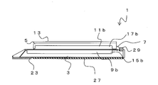
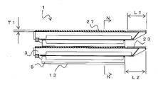
- FIG. 12A is a side view showing a state in which the water stop devices 1 are stacked
- FIG. 12B is a cross-sectional view taken along line NN of FIG. 12A.
- the water stop device 1 can be folded during storage and transportation.
- the water stop devices 1 they are stacked with the bottom surface facing upward, opposite to the installed state.
- the length of the installation member 3 is longer than the length of the upright member 5.
- the water stop structure 30 (see FIG. 11) can sufficiently receive the water pressure against the installation member 3, so that the water stop device 1 can be prevented from tipping backward. Since the installation member 3 is long in this way, a part of the installation member 3 protrudes from the front end portion of the erection member 5 when the erection member 5 is folded.
- the lower surface waterproof member 23 is arranged on the lower surface side near the front end portion of the installation member 3 .
- L1 ⁇ L2 the length of the lower water cutoff member 23 in the front-rear direction
- the lower water stop member 23 does not come into contact with other water stop devices 1 stacked above, and the lower water stop member 23 is crushed or damaged. can be suppressed.
- a convex portion 13 is formed on the outer surface side of the upright member 5 .
- the convex portion 13 is formed in a predetermined range along the front-rear direction at substantially the central portion of the upright member 5 .
- the convex portion 13 is formed at a position avoiding a portion corresponding to the anti-slip member 27 when the waterproof device 1 is folded and stacked. Therefore, when the water stop devices 1 are stacked, the projection 13 of the upper water stop device 1 comes into contact with the lower surface of the installation member 3 of the lower water stop device 1 (part other than the anti-slip member 27).
- T2 ⁇ T1 holds.
- the anti-slip member 27 is not crushed by the other water stop device 1 above, and crushing or damage of the anti-slip member 27 is suppressed. be able to.
- a recess into which the projection 13 fits may be formed on the lower surface of the installation member 3 . Even in this case, if the projection margin of the convex portion 13 is equal to or greater than the thickness of the anti-slip member 27, crushing of the anti-slip member 27 can be suppressed.
- the water stop device 1 since the water stop device 1 can be folded when not in use, it does not take up much space during storage or transportation. Moreover, since the installation member 3 and the standing member 5 can be opened by the hinge portion 7, the water stop device 1 can be repeatedly opened and closed. In addition, by arranging the hinge portion water stop member 29 near the hinge portion 7, when the erecting member 5 is erected, the gap between it and the installation member 3 can be filled, and water stop can be ensured. .
- the installation members 3 can be connected to each other simply by inserting the claw portions 15b of the installation member connection portions 9b into the groove portions 15a of the installation member connection portions 9a from above. Therefore, the installation members 3 can be connected to each other simply by arranging the water stop devices 1 one after another at predetermined positions next to the existing water stop devices 1 . For this reason, there is no need to use other members for connection, and the work of separately attaching a connection member is also unnecessary.
- the claw portion 17b of the standing member connecting portion 11b can be inserted into the groove portion 17a of the standing member connecting portion 11a. , both can be concatenated. For this reason, as with the installation member 3, there is no need to use other members for connection, and there is no need to separately attach a connection member. In this manner, the water stop devices 1 are arranged next to each other one after another, and the work of connecting the water stop devices 1 is completed only by raising the standing member 5, so workability is good.
- connection portion water stop members 21a and 21b are arranged at the respective connection portions, the water stoppage of each connection portion can be ensured simply by connecting the installation members 3 and the standing members 5 together. can be done.
- the interval and angle between the adjacent water stop devices 1 can be arbitrarily adjusted. Therefore, it can be applied even when the ground is not flat or when the water stopping range is curved.
- the installation member 3 can store water. Therefore, by accumulating rainwater or the like in the upper portion of the installation member 3 after installation, the weight of the water stop device 1 is increased, and it is possible to suppress the water stop device 1 from being blown away by wind or the like.
- the water stop device 1 can be turned upside down and stacked. At this time, since the length of the installation member 3 is sufficiently longer than the length of the upright member 5, the upright member 5 does not overlap the lower water cutoff member 23, and crushing of the lower water cutoff member 23 is suppressed. be able to.
- the lower surface of the installation member 3 (stacking) can be A gap can be formed between the upper surface of the standing member 5 (the upper surface when stacked) and the upper surface of the upright member 5 (the lower surface when stacked). Therefore, when the water stop devices 1 are stacked, no load is applied to the anti-slip member 27, and crushing of the lower surface water stop member 23 can be suppressed.
Landscapes
- Engineering & Computer Science (AREA)
- Structural Engineering (AREA)
- Civil Engineering (AREA)
- Architecture (AREA)
- General Engineering & Computer Science (AREA)
- Business, Economics & Management (AREA)
- Emergency Management (AREA)
- Environmental & Geological Engineering (AREA)
- Mechanical Engineering (AREA)
- Barrages (AREA)
- Buildings Adapted To Withstand Abnormal External Influences (AREA)
- Special Wing (AREA)
Abstract
止水装置1は、浸水を防ぐために使用可能な部材であり、保管時や運搬時には、折り畳んで置き、使用時には開いて使用することができる。止水装置1は、主に設置面に設置される設置部材3と、設置部材3に対してヒンジ部7を介して開閉可能な起立部材5等からなる。設置部材3の幅方向の一方の端部側には、第1の設置部材連結部である設置部材連結部9aが設けられる。また、設置部材3の幅方向の他方の端部側には第2の設置部材連結部であるが設置部材連結部9bが設けられる。また、起立部材5の幅方向の一方の端部側には、第1の起立部材連結部である起立部材連結部11aが設けられる。また起立部材5の幅方向の他方の端部側には第2の起立部材連結部である起立部材連結部11b設けられる。
Description
本発明は、例えば、水害の発生時における浸水対策を行うための止水装置に関するものである。
水害が発生した際に、建物などへの浸水を防止する方法として、種々の浸水防止用設備が提案されている。例えば、建物の入り口に、開閉式やスライド式の防水シャッターや防水扉を設けて、必要な際にはシャッターや扉を閉じる方法がある。このような防水用設備は建物と一体で設置される。このため、設備が大掛かりであり、特定の場所でしか利用することができない。
これに対し、簡易的ではあるが、必要な際に特定の場所に運搬して設置する持ち運び式の止水部材がある。例えば、水害の発生時に、土嚢を所定の場所に設置して水をせき止めることで、浸水を防止することができる。しかし、土嚢は重量があり、所定の範囲の浸水を防止するためには、数多くの土嚢が必要となるため、より設置作業性に優れた方法が望まれる。
より設置作業が良好な方法として、略L字状の止水板を用いて止水を行う方法が提案されている(例えば特許文献1)。特許文献1の方法では、L字状の一体型パネルを連結フレームで連結することで、所定の範囲の止水を行うことができる。
しかし、特許文献1の止水部材は略L字状であるため、運搬時や保管時にかさばるという問題がある。
これに対し、折り畳みが可能な略L字状の止水装置が提案されている(特許文献2)。特許文献2の止水装置によれば、運搬時や保管時には折り畳んだ状態とすることができるため、場所をとることがない。
しかし、特許文献1も特許文献2も、複数の止水装置をクリップ状の連結部材で連結するのみであるため、連結部の強度が弱く、また、連結部の止水性も確保することが困難である。また、隣り合う止水板同士を設置した後に、別部材であるクリップで連結する必要があるため、部品点数が多く作業性も悪い。
本発明は、このような問題に鑑みてなされたもので、設置作業性及び止水性能が良好な止水装置を得ることを目的とする。
前述した目的を達成するため、本発明は、浸水を防ぐために使用可能な止水装置であって、設置面に設置する設置部材と、前記設置部材に対してヒンジ部を介して開閉可能な起立部材と、を具備し、前記設置部材の一方の端部側には、第1設置部材連結部が設けられ、前記設置部材の他方の端部側には第2設置部材連結部が設けられ、前記起立部材の一方の端部側には、第1起立部材連結部が設けられ、前記起立部材の他方の端部側には第2起立部材連結部が設けられ、前記第2設置部材連結部は、隣り合う他の止水装置の前記第1設置部材連結部に対して下方に向けて連結させることが可能であるとともに、前記第2起立部材連結部は、隣り合う他の止水装置の前記第1起立部材連結部に対して、前記起立部材の開方向へ向けて連結させることが可能であることを特徴とする止水装置である。
前記ヒンジ部の後方にヒンジ部止水部材が配置され、前記起立部材を前記設置部材に対して起立させた状態において、前記設置部材と前記起立部材とで前記ヒンジ部止水部材が挟み込まれることが望ましい。
前記第1設置部材連結部と前記第2設置部材連結部との連結部、及び、前記第1起立部材連結部と前記第2起立部材連結部との連結部には、それぞれ、連結部止水部材が配置されることが望ましい。
前記第1設置部材連結部と前記第2設置部材連結部は、互いの溝部及び爪部が互いに噛み合うことで連結可能であり、前記第1起立部材連結部と前記第2起立部材連結部は、互いの溝部及び爪部が互いに噛み合うことで連結可能であり、それぞれの連結部において、前記溝部と前記爪部との間にはクリアランスが形成されており、連結方向の連結長さ及び連結角度を調整可能であってもよい。
前記設置部材の下面側には、滑り防止部材が配置され、前記起立部材の外面側には、前記止水装置を畳んで重ねた際における前記滑り防止部材に対応する部位を避けた位置に凸部が形成されてもよい。
前記設置部材の長さは、前記起立部材の長さよりも長く、前記設置部材の前端部近傍における下面側には、止水部材が配置され、前記止水部材の長さをL1とし、前記起立部材の前端からの前記設置部材の前端部のはみ出し長さをL2とすると、
L1≦L2
であってもよい。
L1≦L2
であってもよい。
前記設置部材の上面には貯水部があり、水を貯留することが可能であってもよい。
前記貯水部は、升又はタンク形状であっても良い。
本発明によれば、設置部材と起立部材とがヒンジ部を介して開閉可能であるため、運搬時や保管時には折り畳んだ状態とすることができ、使用時には起立部材を開くことで略L字状にすることができる。また、隣り合う止水装置同士を、設置部材と起立部材のそれぞれについて連結することができる。
また、設置部材連結部は、上方から連結可能であるため、既設の止水装置の隣に新たな止水装置を設置する際に、設置部材を上方から載置するだけで連結部同士を連結することができる。同様に、起立部材連結部は、起立部材の開方向に連結可能であるため、設置部材を配置して、起立部材を起立させるだけで、起立部材同士を連結させることができる。
また、ヒンジ部の後方にヒンジ部止水部材を配置することで、起立部材を設置部材に対して起立させた際に設置部材と起立部材との間の止水性を確保することができる。
また、設置部材連結部と起立部材連結部にそれぞれ止水部材を配置することで、それぞれの連結部においてより確実に止水性を確保することができる。
また、設置部材連結部と起立部材連結部とに、それぞれ溝部と爪部とを設け、互いの溝部と爪部との間にクリアランスを形成することで、連結方向の連結長さ及び連結角度を調整することが可能である。
また、設置部材の下面側に滑り防止部材が配置され、起立部材の外面側に、止水装置を畳んで重ねた際における滑り防止部材に対応する部位を避けた位置に凸部を形成することで、止水装置同士を重ねた際に、滑り防止部材が、重ねられる止水装置の起立部材と接触して損傷することを抑制することができる。
また、設置部材の前端部近傍における下面側に止水部材が配置される場合において、止水部材の長さをL1とし設置部材の前端側への起立部材のはみだし長さをL2とした際に、L1≦L2を満たすようにすることで、止水装置同士を重ねた際に、止水部材が重ねられる止水装置の起立部材と接触して損傷することを抑制することができる。
また、設置部材の上面には貯水部を設けることで、設置部材の内部に水を貯留することが可能である。このため、水を設置部材に貯めることで止水装置の重量を増加させて、風などで飛ばされることを抑制することができる。このような貯水部としては、升又はタンク形状とすればよい。
本発明によれば、設置作業性及び止水性能が良好な止水装置を得ることができる。
以下、本発明の実施の形態を詳細に説明する。図1は、閉じた状態の止水装置1を示す斜視図、図2は、開いた状態の止水装置1の斜視図である。止水装置1は、浸水を防ぐために使用可能な部材であり、保管時や運搬時には、図1に示すように折り畳んでおき、使用時には図2に示すように開いて使用することができる。
止水装置1は、主に地面などの設置面に設置される設置部材3と、設置部材3に対してヒンジ部7(図2参照)を介して開閉可能な起立部材5等からなる。なお、以下の説明において、起立部材5を開く側(図中A方向)を止水装置の前方とし、ヒンジ部7側(図中B方向)を止水装置1の後方とする。また、止水装置1の前後方向に直交する方向(図中C、D方向)を止水装置1の幅方向とする。
設置部材3の幅方向の一方の端部側(図中C方向の端部側)には、第1の設置部材連結部である設置部材連結部9aが設けられる。また、設置部材3の幅方向の他方の端部側(図中D方向の端部側)には第2の設置部材連結部であるが設置部材連結部9bが設けられる。止水装置1を併設した際には、隣り合う止水装置1の設置部材連結部9aと設置部材連結部9bを連結することができる。なお、設置部材連結部9aと設置部材連結部9bの詳細については後述する。
また、起立部材5の幅方向の一方の端部側(図中C方向の端部側)には、第1の起立部材連結部である起立部材連結部11a(図2参照)が設けられる。また起立部材5の幅方向の他方の端部側(図中D方向の端部側)には第2の起立部材連結部である起立部材連結部11b設けられる。止水装置1を併設した際には、隣り合う止水装置1の起立部材連結部11aと起立部材連結部11bを連結することができる。なお、起立部材連結部11aと起立部材連結部11bの詳細については後述する。
図2に示すように、起立部材5を開いた状態では、設置部材3と起立部材5は、一対のストッパ19によって略L字状の状態を維持することができる。なお、ストッパ19は、起立部材5を折り畳んだ状態では、設置部材3と起立部材5の内部に収容可能である。なお、ストッパ19の配置や個数は図示した例には限られない。
図3は、設置部材3の下面を示す図である。設置部材3の下面において、設置部材3の前端側には下面止水部材23が配置される。下面止水部材23は、例えばゴムなど圧縮変形可能な部材で構成される。下面止水部材23は、設置部材3の幅方向の全体に配置される。なお、下面止水部材23の幅方向の端部には、隣り合う止水装置1の下面止水部材23同士が互いに噛み合うように、一部に切り欠き部が形成される。下面止水部材23は、例えばゴム製など圧縮変形可能な部材で構成される。
また、設置部材3の下面止水部材23の後方には、排水溝25が設けられる。排水溝25は、設置部材3の幅方向の略中央であって、下面止水部材23の後方から、設置部材3の後端まで連続する。排水溝25は設置部材3の下面に設けられた溝であり、下面止水部材23を超えて設置部材3の下方に浸入した水を止水装置1の後方へ排出するための部位である。このように設置部材3の下面に排水溝25を設けることで、設置部材3の下方の水による水圧によって、止水装置1を持ち上げようとする力が生じることを抑制することができる。
設置部材3の下面止水部材23の後方であって、排水溝25の両側には、滑り防止部材27が配置される。滑り防止部材27は、止水装置1を地面等の設置面に設置した際に、止水装置1のずれや意図しない移動を抑制するための部材である。滑り防止部材27は、例えばゴムなど圧縮変形可能な部材で構成される。
次に、各部の構造についてより詳細に説明する。図4Aは、閉じた状態の止水装置1の側面図であり、図4Bは、図4Aのヒンジ部7近傍の拡大図である。図5Aは、開いた状態の止水装置1の側面図であり、図5Bは、図5Aのヒンジ部7近傍の拡大図である。
前述したように、設置部材3に対して、ヒンジ部7を介して起立部材5を開くことができる。この際、ヒンジ部7の後方には溝31が形成され、溝31には、ヒンジ部止水部材29が配置される。ヒンジ部止水部材29は、例えばゴムなど圧縮変形可能な部材で構成される。
図5Bに示すように、起立部材5を設置部材3に対して起立させた状態において、設置部材3と起立部材5とでヒンジ部止水部材29が挟み込まれる。より詳細には、起立部材5の後端面と設置部材3の上面がヒンジ部止水部材29と密着する。このため、ヒンジ部7の後方において、設置部材3と起立部材5との間の隙間を、ヒンジ部止水部材29によって止水することができる。
次に、設置部材3についてより詳細に説明する。図6Aは止水装置1を設置した状態を示す平面図であり、図6Bは図6AのE-E線断面図である。設置部材3は、全周にわたって周縁部が起立した側壁が形成される。すなわち、設置部材3の上面は、升形状である。このため、設置部材3の上面は、水32を貯留することが可能な貯水部となる。
このように設置部材3の上部に水32を貯留可能とすることで、止水装置1を設置した後に、水32によって重量を増加させ、止水装置1の錘とすることができる。このため、風などによる止水装置1のずれや移動を抑制することができる。なお、設置部材3の上面に形成される貯水部としては、升形状ではなく、タンク形状であってもよい。
次に、止水装置の設置方法を説明する。図7Aは、設置部材3の連結前の状態を示す正面図であり、図7Bは、設置部材3同士を連結した状態を示す図である。なお、以下の説明において、隣り合う止水装置を区別するため、既設の止水装置1の隣に、新たに止水装置1aを設置するものとして説明するが、止水装置1aは止水装置1と全く同一の構成である。
図7Aに示すように、止水装置1を設置面である地面に載置して、起立部材5を開き、ストッパで固定することで、止水装置1が設置される。次に、既設の止水装置1に対して、止水装置1aを設置する。この際、止水装置1aは、起立部材5を折り畳んだ状態で、止水装置1に隣接するように配置する。
図8Aは、図7Aの状態におけるF部の拡大断面図である。前述したように、止水装置1の一方の端部側(図中左側の端部)には、設置部材連結部9aが設けられる。設置部材連結部9aは、上方に開口した溝部15aを有する。また、溝部15aの外側の側壁部が、上方に向けて突出する凸部15cとなる。
また、止水装置1aの他方の端部側(図中右側の端部)には、設置部材連結部9bが設けられる。設置部材連結部9bは、下方に向けて突出する爪部15bを有する。また、爪部15bの内側には、下方に向けて露出する連結部止水部材21bが設けられる。連結部止水部材21bは、例えばゴムなど圧縮変形可能な部材で構成される。
図7Bは、設置部材3同士が連結された状態を示す正面図であり、図8Bは、図7BのH部における拡大断面図である。止水装置1aを止水装置1の隣に配置する際には、止水装置1aの設置部材連結部9bの爪部15bを、止水装置1の設置部材連結部9aの溝部15aへ挿入する(図中矢印G)。爪部15bを溝部15aへ挿入すると、設置部材連結部9aの凸部15cが、設置部材連結部9bの連結部止水部材21bと密着する。なお、図示した例では、連結部止水部材21bが大きく変形している例を示すが、連結部止水部材21bと凸部15cとが密着できれば、連結部止水部材21bの変形はわずかでよい。
このように、止水装置1aの設置部材連結部9bは、隣り合う他の止水装置1の設置部材連結部9aに対して、下方に向けて連結させることが可能である。このため、既設の止水装置1の隣の所定の位置に、止水装置1aを配置するのみで、設置部材3同士の連結が完了する。この際、設置部材連結部9aと設置部材連結部9bとの連結部には、連結部止水部材21bが配置されるため、連結部における止水性も確保することができる。
ここで、前述したように、設置部材連結部9aと設置部材連結部9bは、溝部15aと爪部15bとを有し、互いの溝部15aと爪部15bが互いに噛み合うことで連結可能である。この際、図8Cに示すように、溝部15aと爪部15bとの間にはクリアランス33が形成される。このため、止水装置1、1aの連結方向の連結長さ(図中J)及び連結角度(図中I)を調整可能である。このようにすることで、止水装置同士の連結長さの調整が可能であるとともに、地面が平らでない場合にも確実に止水装置同士を連結して止水性を確保することができる。
次に、止水装置1aの起立部材5を開いて、設置部材3に対して起立させる。図9Aは、止水装置1aの起立部材5を開く前の平面図であり、図9Bは、起立部材5を開いて起立させた状態を示す平面図である。前述したように、隣り合う止水装置1、1aの設置部材3の端部が連結して重なり合っているため、起立部材5を開くと(図中矢印K)、起立部材5同士にも重なり部が形成される。
図10Aは、図9BのL部における連結前の状態を示す拡大断面図であり、図10Bは、図9BのL部における連結後の状態を示す拡大断面図である。前述したように、止水装置1の一方の端部側(図中左側の端部)には、起立部材連結部11aが設けられる。起立部材連結部11aは、起立させた際の前方(閉じた際の下面側)に開口した溝部17aを有する。また、溝部17aの側壁部が、前方(閉じた際の下面側)に向けて突出する凸部17cとなる。
また、止水装置1aの他方の端部側(図中右側の端部)には、起立部材連結部11bが設けられる。起立部材連結部11bは、起立させた際の後方(閉じた際の上面側)に向けて突出する爪部17bを有する。また、爪部17bの内側には爪部17bの突出方向に露出する連結部止水部材21aが設けられる。連結部止水部材21aは、例えばゴムなど圧縮変形可能な部材で構成される。
止水装置1aの起立部材5を開くと、止水装置1aの起立部材連結部11bの爪部17bが、止水装置1の起立部材連結部11aの溝部17aへ挿入される。爪部17bが溝部17aへ挿入されると、起立部材連結部11aの凸部17cが、起立部材連結部11bの連結部止水部材21aと密着する。以上により、起立部材5同士が連結される。
このように、止水装置1aの起立部材連結部11bは、隣り合う他の止水装置1の起立部材連結部11aに対して、起立部材5の開方向へ向けて連結させることが可能である。このため、既設の止水装置1の隣の所定の位置に、止水装置1aを配置して設置部材3同士が連結し、止水装置1aの起立部材5を開くだけで、起立部材5同士の連結が完了する。この際、起立部材連結部11aと起立部材連結部11bとの連結部には、連結部止水部材21aが配置されるため、連結部における止水性も確保することができる。
ここで、設置部材3同士の連結部と同様に、起立部材連結部11aと起立部材連結部11bは、溝部17aと爪部17bとを有し、互いの溝部17aと爪部17bが互いに噛み合うことで連結可能である。この際、図10Cに示すように、溝部17aと爪部17bとの間にはクリアランス35が形成される。このため、止水装置1、1aの連結方向の連結長さ(図中M)及び連結角度(図中L)を調整可能である。このようにすることで、止水装置同士の連結長さ調整が可能であるとともに、止水装置同士を所定の角度で曲げて連結することができる。
なお、上述した例では、設置部材連結部9bに連結部止水部材21aを配置したが、設置部材連結部9a側に設けてもよい。同様に、起立部材連結部11bに連結部止水部材21aを配置したが、起立部材連結部11a側に設けてもよい。また、設置部材連結部9aに溝部15aを設け、設置部材連結部9bに爪部15bを設けたが、設置部材連結部9aに爪部15bを設け、設置部材連結部9bに溝部15aを設けてもよい。同様に、起立部材連結部11aに溝部17aを設け、起立部材連結部11bに爪部17bを設けたが、起立部材連結部11aに爪部17bを設け、起立部材連結部11bに溝部17aを設けてもよい。
図11は、複数の止水装置を連結して形成した止水構造30を示す概念図である。止水装置1を幅方向(図中C、D方向)に複数連結し、所定の長さに形成することで、止水装置1の前方側(図中A方向)からの水を、止水装置1(起立部材5)によってせき止めることができる。
なお、起立部材5の前面側には水圧がかかるが、設置部材3の上方にも水圧がかかるため、止水装置1が倒れることがない。また、設置部材3の上方からの水圧によって、下面止水部材23(図3参照)が地面に押し付けられるため、下面止水部材23が地面に密着し、設置部材3の下面への水の流出を抑制することができる。また、設置部材3の上方からの水圧によって、滑り防止部材27(図3参照)が地面に押し付けられるため、滑り防止部材27が地面に密着し、止水装置1がずれることを抑制することができる。
また、前述したように、ヒンジ部7の後方にヒンジ部止水部材29が配置されるため、設置部材3と起立部材5との隙間からの水の流出を抑制することができる。また、起立部材連結部11a、11bの連結部、及び、設置部材連結部9a、9bの連結部に、それぞれ、連結部止水部材21a、21bが配置されるため、止水装置同士の隙間からの水の流出を抑制することができる。このように止水構造30によれば、止水装置1の後方(図中B方向)への水の流出を抑制することができる。
次に、止水装置1の保管及び運搬方法について説明する。図12Aは、止水装置1を積み重ねた状態を示す側面図であり、図12Bは、図12AのN-N線断面図である。前述したように、止水装置1は、保管及び運搬時には折り畳んだ状態とすることができる。なお、止水装置1を積み重ねる際には、底面を上方に向けて、設置状態とは逆向きにして積層させる。
図示したように、設置部材3の長さは、起立部材5の長さよりも長い。このようにすることで、止水構造30(図11参照)において、設置部材3に対する水圧を十分に受けることができるため、止水装置1の後方への転倒を抑制することができる。このように設置部材3の長さが長いため、起立部材5を折り畳んだ際に、起立部材5の前端部から設置部材3の一部がはみ出す。
ここで、前述したように、設置部材3の前端部近傍における下面側には、下面止水部材23が配置される。この際、下面止水部材23の前後方向の長さをL1とし、起立部材5の前端からの設置部材3の前端部のはみ出し長さをL2とすると、
L1≦L2
が成立する。
L1≦L2
が成立する。
このようにすることで、止水装置1を積み重ねても、下面止水部材23が、上方に重ねられた他の止水装置1と接触することがなく、下面止水部材23が潰れたり傷ついたりすることを抑制することができる。
また、図1に示すように、起立部材5の外面側には、凸部13が形成される。凸部13は、起立部材5の略中央部に、前後方向に沿って所定の範囲に形成される。なお、凸部13は、止水装置1を畳んで重ねた際における滑り防止部材27に対応する部位を避けた位置に形成される。したがって、止水装置1を積み重ねると、上方の止水装置1の凸部13が、下方の止水装置1の設置部材3の下面(滑り防止部材27以外の部位)と接触する。
ここで、図12Aに示すように、滑り防止部材27の厚みをT1とし、図12Bに示すように、凸部13の突出高さをT2とすると、
T2≧T1
が成立する。
T2≧T1
が成立する。
このようにすることで、止水装置1を積み重ねても、滑り防止部材27が上方の他の止水装置1によって押しつぶされることがなく、滑り防止部材27が潰れたり傷ついたりすることを抑制することができる。
なお、止水装置1同士を積み重ねた際に、止水装置1同士のずれを防止するため、例えば、設置部材3の下面に、凸部13が嵌り込むような凹部を形成してもよい。この場合でも、凸部13の突出代が滑り防止部材27の厚み以上であれば、滑り防止部材27の潰れ等を抑制することができる。
以上、本実施の形態によれば、止水装置1は、使用時以外は折り畳むことができるため、保管時や運搬時に場所をとることがない。また、止水装置1は、ヒンジ部7によって設置部材3と起立部材5とを開くことができるため、開閉を繰り返すことが可能である。また、ヒンジ部7の近傍にヒンジ部止水部材29を配置することで、起立部材5を起立させた際に、設置部材3との間の隙間を埋めて、止水性を確保することができる。
また、設置部材連結部9bの爪部15bを、上方から設置部材連結部9aの溝部15aに挿入するだけで設置部材3同士を連結することができる。このため、既設の止水装置1の隣の所定の位置に、止水装置1を次々に配置するだけで設置部材3同士を連結することができる。このため、連結のために他の部材を用いる必要がなく、また、連結部材を別途取り付ける作業も不要である。
また、既設の止水装置1の隣に設置した止水装置1の起立部材5を起立させるだけで、起立部材連結部11bの爪部17bを、起立部材連結部11aの溝部17aに挿入して、両者を連結することができる。このため、設置部材3と同様に、連結のために他の部材を用いる必要がなく、また、連結部材を別途取り付ける作業も不要である。このように、止水装置1同士を次々に隣り合わせに配置して、起立部材5を起こすだけで止水装置1同士の連結作業が完了するため、作業性が良好である。
また、それぞれの連結部には、連結部止水部材21a、21bが配置されているため、設置部材3同士及び起立部材5同士を連結するだけで、それぞれの連結部の止水性を確保することができる。
また、それぞれの連結部において、爪部と溝部との間にクリアランスを設けることで、隣り合う止水装置1同士の間隔や角度を任意に調整することができる。このため、地面が平坦でない場合や止水範囲が湾曲している場合にも適用が可能である。
また、設置部材3には水を貯留することができる。このため、設置した後に雨水等を設置部材3の上部に貯めることで、止水装置1の重量が増加し、風などで止水装置1が飛ばされることを抑制することができる。
また、保管時には、止水装置1を上下逆さまにして重ねることが可能である。この際、設置部材3の長さが起立部材5の長さよりも十分に長いため、下面止水部材23の上に起立部材5が重なることがなく、下面止水部材23の潰れ等を抑制することができる。
また、設置部材3の下面の滑り防止部材27を避けた位置であって、起立部材5の上面に凸部13を形成することで、凸部13の突出代分だけ設置部材3の下面(積み重ねた際の上面)と起立部材5の上面(積み重ねた際の下面)の間に隙間を形成することができる。このため、止水装置1を積み重ねた際に、滑り防止部材27に荷重がかかることがなく、下面止水部材23の潰れ等を抑制することができる。
以上、添付図を参照しながら、本発明の実施の形態を説明したが、本発明の技術的範囲は、前述した実施の形態に左右されない。当業者であれば、特許請求の範囲に記載された技術的思想の範疇内において各種の変更例または修正例に想到し得ることは明らかであり、それらについても当然に本発明の技術的範囲に属するものと了解される。
1、1a……止水装置
3………設置部材
5………起立部材
7………ヒンジ部
9a、9b………設置部材連結部
11a、11b………起立部材連結部
13………凸部
15a、17a………溝部
15b、17b………爪部
15c、17c………凸部
19………ストッパ
21a、21b………連結部止水部材
23………下面止水部材
25………排水溝
27………滑り防止部材
29………ヒンジ部止水部材
30………止水構造
31………溝
32………水
33、35………クリアランス
3………設置部材
5………起立部材
7………ヒンジ部
9a、9b………設置部材連結部
11a、11b………起立部材連結部
13………凸部
15a、17a………溝部
15b、17b………爪部
15c、17c………凸部
19………ストッパ
21a、21b………連結部止水部材
23………下面止水部材
25………排水溝
27………滑り防止部材
29………ヒンジ部止水部材
30………止水構造
31………溝
32………水
33、35………クリアランス
Claims (8)
- 浸水を防ぐために使用可能な止水装置であって、
設置面に設置する設置部材と、
前記設置部材に対してヒンジ部を介して開閉可能な起立部材と、
を具備し、
前記設置部材の一方の端部側には、第1設置部材連結部が設けられ、前記設置部材の他方の端部側には第2設置部材連結部が設けられ、
前記起立部材の一方の端部側には、第1起立部材連結部が設けられ、前記起立部材の他方の端部側には第2起立部材連結部が設けられ、
前記第2設置部材連結部は、隣り合う他の止水装置の前記第1設置部材連結部に対して下方に向けて連結させることが可能であるとともに、前記第2起立部材連結部は、隣り合う他の止水装置の前記第1起立部材連結部に対して、前記起立部材の開方向へ向けて連結させることが可能であることを特徴とする止水装置。 - 前記ヒンジ部の後方にヒンジ部止水部材が配置され、前記起立部材を前記設置部材に対して起立させた状態において、前記設置部材と前記起立部材とで前記ヒンジ部止水部材が挟み込まれることを特徴とする請求項1記載の止水装置。
- 前記第1設置部材連結部と前記第2設置部材連結部との連結部、及び、前記第1起立部材連結部と前記第2起立部材連結部との連結部には、それぞれ、連結部止水部材が配置されることを特徴とする請求項1記載の止水装置。
- 前記第1設置部材連結部と前記第2設置部材連結部は、互いの溝部及び爪部が互いに噛み合うことで連結可能であり、
前記第1起立部材連結部と前記第2起立部材連結部は、互いの溝部及び爪部が互いに噛み合うことで連結可能であり、
それぞれの連結部において、前記溝部と前記爪部との間にはクリアランスが形成されており、連結方向の連結長さ及び連結角度を調整可能であることを特徴とする請求項1記載の止水装置。 - 前記設置部材の下面側には、滑り防止部材が配置され、
前記起立部材の外面側には、前記止水装置を畳んで重ねた際における前記滑り防止部材に対応する部位を避けた位置に凸部が形成されることを特徴とする請求項1記載の止水装置。 - 前記設置部材の長さは、前記起立部材の長さよりも長く、
前記設置部材の前端部近傍における下面側には、止水部材が配置され、
前記止水部材の長さをL1とし、前記起立部材の前端からの前記設置部材の前端部のはみ出し長さをL2とすると、
L1≦L2
であることを特徴とする請求項1記載の止水装置。 - 前記設置部材の上面には貯水部があり、水を貯留することが可能であることを特徴とする請求項1記載の止水装置。
- 前記貯水部は、升又はタンク形状であることを特徴とする請求項7に記載の止水装置。
Applications Claiming Priority (2)
| Application Number | Priority Date | Filing Date | Title |
|---|---|---|---|
| JP2021-065126 | 2021-04-07 | ||
| JP2021065126A JP7354177B2 (ja) | 2021-04-07 | 2021-04-07 | 止水装置 |
Publications (1)
| Publication Number | Publication Date |
|---|---|
| WO2022215643A1 true WO2022215643A1 (ja) | 2022-10-13 |
Family
ID=83546101
Family Applications (1)
| Application Number | Title | Priority Date | Filing Date |
|---|---|---|---|
| PCT/JP2022/016477 Ceased WO2022215643A1 (ja) | 2021-04-07 | 2022-03-31 | 止水装置 |
Country Status (2)
| Country | Link |
|---|---|
| JP (1) | JP7354177B2 (ja) |
| WO (1) | WO2022215643A1 (ja) |
Families Citing this family (2)
| Publication number | Priority date | Publication date | Assignee | Title |
|---|---|---|---|---|
| JP7444828B2 (ja) * | 2021-09-28 | 2024-03-06 | 古河電気工業株式会社 | 止水装置、止水構造 |
| JP7444829B2 (ja) * | 2021-09-28 | 2024-03-06 | 古河電気工業株式会社 | 止水装置、止水構造 |
Citations (4)
| Publication number | Priority date | Publication date | Assignee | Title |
|---|---|---|---|---|
| JP2001140235A (ja) * | 1999-11-11 | 2001-05-22 | Mitsuyori Nakajima | 遮水装置 |
| JP2012031658A (ja) * | 2010-07-30 | 2012-02-16 | Nikkei Hokkaido Co Ltd | 止水装置 |
| JP2016108897A (ja) * | 2014-12-10 | 2016-06-20 | タキロン株式会社 | 止水装置 |
| JP2019504954A (ja) * | 2016-02-04 | 2019-02-21 | 南京軍理科技股▲ふん▼有限公司 | 自動防水装置 |
-
2021
- 2021-04-07 JP JP2021065126A patent/JP7354177B2/ja active Active
-
2022
- 2022-03-31 WO PCT/JP2022/016477 patent/WO2022215643A1/ja not_active Ceased
Patent Citations (4)
| Publication number | Priority date | Publication date | Assignee | Title |
|---|---|---|---|---|
| JP2001140235A (ja) * | 1999-11-11 | 2001-05-22 | Mitsuyori Nakajima | 遮水装置 |
| JP2012031658A (ja) * | 2010-07-30 | 2012-02-16 | Nikkei Hokkaido Co Ltd | 止水装置 |
| JP2016108897A (ja) * | 2014-12-10 | 2016-06-20 | タキロン株式会社 | 止水装置 |
| JP2019504954A (ja) * | 2016-02-04 | 2019-02-21 | 南京軍理科技股▲ふん▼有限公司 | 自動防水装置 |
Also Published As
| Publication number | Publication date |
|---|---|
| JP2022160750A (ja) | 2022-10-20 |
| JP7354177B2 (ja) | 2023-10-02 |
Similar Documents
| Publication | Publication Date | Title |
|---|---|---|
| JP7354177B2 (ja) | 止水装置 | |
| JP6478423B2 (ja) | パネル支持装置 | |
| CN1255177A (zh) | 用于建立拦阻液体防护堤岸的筑坝装置 | |
| EP2395562A2 (fr) | Structure de solidarisation de panneaux photovoltaïques sur un bâti | |
| JP2012508966A (ja) | 太陽電池アレイ周辺アセンブリのためのフレキシブル風向偏向部材 | |
| KR101581186B1 (ko) | 기밀구조가 강화된 수리용 수문 | |
| JP2016186208A (ja) | 開口部の防水装置 | |
| CN217680883U (zh) | 一种可自主复位的隔震缝盖板装置 | |
| JP2023048834A (ja) | 止水装置、止水構造 | |
| JP7444829B2 (ja) | 止水装置、止水構造 | |
| JP2019123989A (ja) | 開口部の防水装置 | |
| JP2011047160A (ja) | モバイル式越水防止装置 | |
| JP7584086B2 (ja) | 止水装置 | |
| JP7558999B2 (ja) | 止水装置、止水構造 | |
| KR102016285B1 (ko) | 태양광 패널 구조체 연결구조 | |
| JP2010203158A (ja) | 止水壁 | |
| KR102603892B1 (ko) | 침수 예방용 수동 차수문 | |
| KR102036733B1 (ko) | 탄성부재를 이용한 차수장치 | |
| US10787780B2 (en) | Flood prevention device | |
| GB2383071A (en) | Flood barrier | |
| JP7199315B2 (ja) | 止水板及びこれを用いた建物開口の止水構造 | |
| KR101829434B1 (ko) | 항만구조물의 케이슨 | |
| KR20170037041A (ko) | 내풍압 셔터의 결합구조 | |
| JP2019183590A (ja) | 高さ可変型堤防装置 | |
| KR102607021B1 (ko) | 윙바디 적재함의 개구 차단장치 |
Legal Events
| Date | Code | Title | Description |
|---|---|---|---|
| 121 | Ep: the epo has been informed by wipo that ep was designated in this application |
Ref document number: 22784627 Country of ref document: EP Kind code of ref document: A1 |
|
| NENP | Non-entry into the national phase |
Ref country code: DE |
|
| 122 | Ep: pct application non-entry in european phase |
Ref document number: 22784627 Country of ref document: EP Kind code of ref document: A1 |