WO2022215246A1 - 道路監視システム、道路監視装置、道路監視方法、及び非一時的なコンピュータ可読媒体 - Google Patents
道路監視システム、道路監視装置、道路監視方法、及び非一時的なコンピュータ可読媒体 Download PDFInfo
- Publication number
- WO2022215246A1 WO2022215246A1 PCT/JP2021/015007 JP2021015007W WO2022215246A1 WO 2022215246 A1 WO2022215246 A1 WO 2022215246A1 JP 2021015007 W JP2021015007 W JP 2021015007W WO 2022215246 A1 WO2022215246 A1 WO 2022215246A1
- Authority
- WO
- WIPO (PCT)
- Prior art keywords
- pattern
- road
- range
- vehicle
- road monitoring
- Prior art date
- Legal status (The legal status is an assumption and is not a legal conclusion. Google has not performed a legal analysis and makes no representation as to the accuracy of the status listed.)
- Ceased
Links
Images



Classifications
-
- G—PHYSICS
- G08—SIGNALLING
- G08G—TRAFFIC CONTROL SYSTEMS
- G08G1/00—Traffic control systems for road vehicles
- G08G1/01—Detecting movement of traffic to be counted or controlled
- G08G1/052—Detecting movement of traffic to be counted or controlled with provision for determining speed or overspeed
-
- G—PHYSICS
- G02—OPTICS
- G02B—OPTICAL ELEMENTS, SYSTEMS OR APPARATUS
- G02B6/00—Light guides; Structural details of arrangements comprising light guides and other optical elements, e.g. couplings
- G02B6/10—Light guides; Structural details of arrangements comprising light guides and other optical elements, e.g. couplings of the optical waveguide type
- G02B6/12—Light guides; Structural details of arrangements comprising light guides and other optical elements, e.g. couplings of the optical waveguide type of the integrated circuit kind
- G02B6/12002—Three-dimensional structures
-
- G—PHYSICS
- G08—SIGNALLING
- G08G—TRAFFIC CONTROL SYSTEMS
- G08G1/00—Traffic control systems for road vehicles
-
- G—PHYSICS
- G08—SIGNALLING
- G08G—TRAFFIC CONTROL SYSTEMS
- G08G1/00—Traffic control systems for road vehicles
- G08G1/01—Detecting movement of traffic to be counted or controlled
- G08G1/0104—Measuring and analyzing of parameters relative to traffic conditions
- G08G1/0108—Measuring and analyzing of parameters relative to traffic conditions based on the source of data
- G08G1/0116—Measuring and analyzing of parameters relative to traffic conditions based on the source of data from roadside infrastructure, e.g. beacons
-
- G—PHYSICS
- G08—SIGNALLING
- G08G—TRAFFIC CONTROL SYSTEMS
- G08G1/00—Traffic control systems for road vehicles
- G08G1/01—Detecting movement of traffic to be counted or controlled
- G08G1/0104—Measuring and analyzing of parameters relative to traffic conditions
- G08G1/0125—Traffic data processing
- G08G1/0133—Traffic data processing for classifying traffic situation
-
- G—PHYSICS
- G08—SIGNALLING
- G08G—TRAFFIC CONTROL SYSTEMS
- G08G1/00—Traffic control systems for road vehicles
- G08G1/01—Detecting movement of traffic to be counted or controlled
- G08G1/02—Detecting movement of traffic to be counted or controlled using treadles built into the road
-
- G—PHYSICS
- G08—SIGNALLING
- G08G—TRAFFIC CONTROL SYSTEMS
- G08G1/00—Traffic control systems for road vehicles
- G08G1/01—Detecting movement of traffic to be counted or controlled
- G08G1/04—Detecting movement of traffic to be counted or controlled using optical or ultrasonic detectors
-
- G—PHYSICS
- G02—OPTICS
- G02B—OPTICAL ELEMENTS, SYSTEMS OR APPARATUS
- G02B6/00—Light guides; Structural details of arrangements comprising light guides and other optical elements, e.g. couplings
- G02B6/10—Light guides; Structural details of arrangements comprising light guides and other optical elements, e.g. couplings of the optical waveguide type
- G02B6/12—Light guides; Structural details of arrangements comprising light guides and other optical elements, e.g. couplings of the optical waveguide type of the integrated circuit kind
- G02B2006/12133—Functions
- G02B2006/12138—Sensor
Definitions
- the present invention for example, relates to technology for monitoring the operation of vehicles using optical fiber sensors.
- Optical fiber sensing is a technology that uses optical fibers as sensors such as vibration, temperature, or strain.
- One application of optical fiber sensing is traffic flow bird's-eye view monitoring.
- bird's-eye view monitoring of traffic flow means to bird's-eye view of traffic flow conditions (for example, traveling speed of vehicles, traffic congestion, etc.) at a certain point in time in a certain geographical area (for example, map).
- traffic flow monitoring on expressways is performed using existing sensors such as traffic meters and CCTV (Closed-circuit Television).
- CCTV Camera-circuit Television
- optical fiber sensing can be used instead of installing a huge number of sensors.
- traffic flow bird's-eye view monitoring using optical fiber sensing the running trajectory of a vehicle is grasped by continuously measuring the time and distance of the vibration generated by the running of the vehicle.
- traffic information such as the speed of the vehicle from this travel locus
- the state of the traffic flow is monitored.
- Patent Document 1 discloses an example of technology for overhead monitoring of traffic flow using optical fiber sensing.
- an optical fiber cable laid along the road is used as a sensing medium for detecting vibration accompanying vehicle travel.
- the road monitoring system of Patent Document 1 can monitor traffic conditions of vehicles traveling on the road.
- the present invention has been made in view of the above-mentioned problems, and its main purpose is to improve the accuracy of vehicle speed calculation.
- a road monitoring system includes an optical fiber cable laid on a road, a receiving means for receiving an optical signal from the optical fiber cable, and based on the received optical signal, a first time range and a first pattern extracting means for extracting a first pattern corresponding to the running state of the vehicle on the road in the distance range; pattern conversion means for generating a reduced second pattern; and calculation means for calculating the running speed of the vehicle on the road based on the second pattern.
- the road monitoring device includes receiving means for receiving an optical signal from an optical fiber cable laid on the road, and based on the received optical signal, the road in the first time range and the first distance range.
- pattern extracting means for extracting a first pattern according to the running state of the vehicle; It includes pattern conversion means for generating two patterns, and calculation means for calculating the traveling speed of the vehicle on the road based on the second pattern.
- a road monitoring method includes: a first time range and a first distance range based on an optical signal received from an optical fiber cable laid on the road; Extracting a pattern, generating a second pattern based on the first pattern in which the number of time points included in the first time range or the number of positions included in the first distance range is reduced, and based on the second pattern, Calculate the running speed of the vehicle on the road.
- a non-transitory computer readable medium is provided to a computer included in a road monitoring device for determining a first range of time and a first range of distance based on optical signals received from a fiber optic cable laid on a road.
- a road monitoring program for executing a process of generating a second pattern and a process of calculating the running speed of the vehicle on the road based on the second pattern is stored.
- FIG. 2 is a schematic diagram showing an example of a travel locus obtained by measuring an amount of environmental variation caused by a vehicle traveling on a road with an optical fiber sensor;
- FIG. 4 is a schematic diagram showing an example of an ideal running locus;
- FIG. 4 is a schematic diagram showing an example of an unclear travel locus;
- FIG. 10 is a schematic diagram showing an example of extracting a travel locus with an erroneous inclination from an ambiguous travel locus.
- FIG. 5 is a schematic diagram showing an operation for clarifying an unclear travel locus; It is a block diagram which shows an example of a structure of the road monitoring system in 3rd Embodiment of this invention. It is a flowchart which shows the operation
- FIG. 4 is a schematic diagram showing an example of data width in the direction of distance and time possessed by a travel locus. It is a block diagram which shows an example of a structure of the road monitoring system in 4th Embodiment of this invention.
- FIG. 5 is a schematic diagram showing an operation for clarifying an unclear travel locus; It is a block diagram showing an example of hardware constitutions which can realize a road monitoring device in each embodiment of the present invention.
- FIG. 1 is a block diagram showing an example configuration of a road monitoring system according to the first embodiment of the present invention.
- the road monitoring system (100) in this embodiment includes an optical fiber cable (11) and a road monitoring device (120).
- the optical fiber cable (11) is an optical fiber cable for communication and is laid on roads.
- the road monitoring device (120) includes a receiver (150), a pattern extractor (220), a pattern converter (230), and a calculator (240).
- the receiver (150) receives the optical signal from the optical fiber cable (11).
- the optical signal received by the receiver (150) is a time series of detected values (hereinafter referred to as "environmental variation") detected in the optical fiber cable (11).
- the environmental fluctuation amount changes according to the vibration generated in the environment in which the optical fiber cable (11) is laid.
- the environmental fluctuation amount is, for example, the backscattered light of the signal transmitted to the optical fiber cable (11).
- the time series of the environmental fluctuation amount is superposition of pulses caused by vibrations independently generated at each position in the length direction of the optical fiber cable (11), and the time width of the pulse is compared to the time width required for the propagation of the pulse. is sufficiently short, and the pulse is sufficiently coarse.
- the timing at which each pulse is detected can be associated with the generation position of each pulse in the optical fiber cable (11).
- the road vibrates, and due to the road vibration, an environmental variation pulse is generated in the optical fiber cable (11) laid on the road.
- a pattern extraction unit (220) extracts a first pattern according to the running state of the vehicle on the road in the first time range and the first distance range based on the received optical signal.
- the first pattern is a time series of environmental variation in which each environmental variation is associated with its occurrence position.
- the pattern conversion unit (230) generates a second pattern by reducing the number of points in the first time range or the number of positions in the first distance range based on the first pattern.
- the “distance range” is the range of distance in the length direction of the optical fiber cable (11).
- the “number of positions” is the number of distance units included in a certain “distance range”.
- time range is the range of time in which a series of time series of environmental variation is detected.
- the second pattern is, like the first pattern, a time series of environmental fluctuations in which each environmental fluctuation is associated with its occurrence position.
- the number of environmental fluctuations (the number of positions and the number of hours) included in the time series of the environmental fluctuations is different.
- a calculation unit (240) calculates the traveling speed of the vehicle on the road based on the second pattern.
- the calculator (240) continuously detects the time series of the amount of environmental variation to detect the time change of the vibration generation position in the optical fiber cable (11) (that is, the running of the vehicle).
- the calculation unit (240) calculates the traveling speed of the vehicle, for example, based on the traveling locus of the vehicle in the second pattern.
- the calculation unit (240) calculates the traveling speed of the vehicle, for example, by linearly approximating the traveling locus.
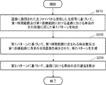
- FIG. 2 is a flowchart showing operations in the first embodiment of the present invention.
- the pattern extraction unit (220) extracts a first pattern according to the running state of the vehicle on the road in the first time range and the first distance range based on the received optical signal (step S210).
- the pattern conversion unit (230) generates a second pattern in which the number of points included in the first time range or the number of positions included in the first distance range is reduced based on the first pattern (step S220).
- the calculator (240) calculates the running speed of the vehicle on the road based on the second pattern (step S230).
- the pattern extraction unit (220) detects the running state of the vehicle on the road in the first time range and the first distance range based on the received optical signal. to extract a first pattern corresponding to .
- the pattern conversion unit (230) generates a second pattern by reducing the number of points in the first time range or the number of positions in the first distance range based on the first pattern.
- the travel locus of the vehicle in the second pattern is narrower than the travel locus of the vehicle in the first pattern.
- a calculation unit (240) calculates the traveling speed of the vehicle on the road based on the second pattern, which is narrower than the traveling locus of the vehicle in the first pattern, more accurately than the first pattern. Therefore, the road monitoring device (120) in this embodiment has the effect of being able to improve the accuracy of vehicle speed calculation.
- the pattern conversion unit (230) may determine the number of points in the first time range or the number of positions in the first distance range so that the vehicle travel locus in the second pattern does not disappear.
- the road monitoring device (120) in this embodiment has the effect of being able to suppress failures in calculating the vehicle speed.
- FIG. 3 is a block diagram showing an example configuration of a road monitoring system according to the second embodiment of the present invention.
- the road monitoring system (105) of the present embodiment is a detection value (environmental fluctuation amount) detected in the optical fiber cable (11) that changes according to vibrations generated in the environment in which the optical fiber cable (11) is laid.
- the environmental fluctuation amount is the magnitude of the backscattered light of the transmission signal in the optical fiber cable (11).
- the road monitoring system (105) continuously detects the time series of the amount of environmental variation to detect the time change of the vibration generation position (that is, vehicle travel) in the optical fiber cable (11).
- the road monitoring system (105) calculates traffic information including the traveling speed of the vehicle based on the time series of the environmental variation.
- the traffic information may further include information such as vehicle spacing, vehicle acceleration, number of vehicles, or direction of travel of the vehicle.
- the road monitoring system (105) comprises a fiber optic cable (11) and a road monitoring device (125).
- the road monitoring device (125) has a transmitter (13), a circulator (14), a receiver (155), and an output (113).
- the transmitter (13) transmits optical pulses to the circulator (14) via the optical path.
- a circulator (14) outputs an optical pulse transmitted from a transmitter (13) to an optical fiber cable (11), and circulates backscattered light of the optical pulse returning from the optical fiber cable (11) through an optical path. Output to the receiver (155).
- the receiving section (155) calculates traffic information based on the backscattered light received from the circulator (14), and outputs the calculated traffic information to the output section (113).
- the output unit (113) outputs traffic information to the outside.
- the receiving section (155) includes a detector (16), a data processing section (17), a memory (18), a data format changing section (195) (an example of a pattern extracting section and a pattern converting section), and a trajectory extracting section (110). (an example of a calculation unit), a data extraction unit (111) (an example of a calculation unit), and a traffic information calculation unit (112).
- the detector (16) converts the backscattered light of the received light pulse into an electric signal and outputs the converted electric signal to the data processing unit (17).
- the data processing unit (17) acquires the amount of environmental variation by converting the input electrical signal, which is analog data, into digital data, and outputs it to the memory (18).
- the memory (18) accumulates data representing the time series of the environmental variation (environmental variation data) for a predetermined period of time in a format that allows calculation of the position where each environmental variation occurs.
- the data format changing unit (195) determines the range of distance and time for which traffic information should be calculated (traffic information calculation range). In addition, the data format changing unit (195) extends the traffic information calculation range in the direction of distance and time, and corresponds to the range of distance and time (trajectory extraction range) used for extracting the traveling trajectory of the vehicle. Derive the range of variation data. The data format changing unit (195) also copies the environmental variation data of the derived range to the locus extraction range storage area in the memory (18). Also, the data format changing unit (195) reduces the copied environmental variation data so that the distance width and time width of the trajectory extraction range are the same as before the extension.
- a trajectory extraction unit (110) extracts a travel trajectory based on the environmental variation data stored in the trajectory extraction range storage area.
- the data extraction unit (111) calculates the traveling speed of the vehicle based on the extracted data representing the traveling locus.
- a traffic information calculation unit (112) generates traffic information based on the traveling speed of the vehicle, the traveling locus of the vehicle, and the like. [Explanation of operation] The operation of the road monitoring system (105) will now be described with reference to FIGS.
- FIG. 4 is a flow chart showing the operation in the second embodiment of the invention.
- the data processing unit (17) acquires the time series of the environmental fluctuation amount that fluctuates due to the vibration applied to the optical fiber cable (11) due to the running of the vehicle (step S01).
- the timing at which each environmental variation is detected is associated with the position of occurrence of each environmental variation in the optical fiber cable (11). is possible. Therefore, the data processing unit (17) can calculate the position where each environmental variation occurs by, for example, associating the environmental variation when the optical pulse was transmitted with information on the time when the optical pulse was transmitted.
- the memory (18) accumulates the acquired environmental variation data for a predetermined period of time in a format that enables calculation of the position of occurrence of each environmental variation (step S02).
- the memory (18) stores environmental variation data in which, for example, information on the time when the optical pulse was transmitted is associated with the environmental variation when the optical pulse was transmitted.
- the data format changing unit (195) determines the traffic information calculation range (step S03).
- the data format changer (195) determines the traffic information calculation range, for example, based on the settings held by the road monitoring device (125).
- the data format changing unit (195) derives the range of environmental variation data corresponding to the trajectory extraction range. Then, the data format changing unit (195) copies the environmental variation data of the derived range to the storage area of the trajectory extraction range on the memory (18) (step S04).
- the trajectory extraction range includes the traffic information calculation range and is wider than the traffic information calculation range.
- the data format changing unit (195) reduces the copied environmental variation data so that the distance width and time width of the trajectory extraction range are the same as before extension (step S05).
- the traffic information calculation range is, for example, the range of 1 km and 1 minute when calculating the traffic information including the average vehicle speed of 1 km (kilometer) x 1 minute, and the traffic information of 2 km x 2 minutes is calculated. 2 km and 2 minutes range.
- the environmental variation data included in the trajectory extraction range storage area is thinned in half. More specifically, for example, environmental variation data corresponding to odd-numbered distances and odd-numbered times are deleted.
- the trajectory extraction unit (110) extracts the travel trajectory based on the environmental variation data stored in the trajectory extraction range storage area (step S06).
- the trajectory extraction unit (110) linearly approximates, for example, a band of values (high values) larger than a predetermined threshold in the environmental variation data distributed on a plane with distance and time axes, using the least squares method. to extract the running locus.
- the data extraction unit (111) calculates the traveling speed of the vehicle based on the extracted data representing the traveling locus (step S07).
- a data extraction unit (111) calculates the running speed of the vehicle, for example, based on the slope of the approximate straight line described above.
- the traffic information calculation unit (112) calculates traffic information including, for example, the average speed of the vehicle based on the vehicle traveling speed calculated in step S07 and the vehicle traveling trajectory extracted in step S06. Generate (step S08).
- traffic information including, for example, the average speed of the vehicle based on the vehicle traveling speed calculated in step S07 and the vehicle traveling trajectory extracted in step S06.
- step S08 Generate (step S08).
- the vertical axis of the graph is time and the horizontal axis of the graph is distance.
- the solid line represents the trajectory of the vehicle
- the hatched band represents the high value of the environmental variation
- the dashed line represents the trajectory of the vehicle extracted from the environmental variation.
- FIG. 5 is a schematic diagram showing an example of a travel locus obtained by measuring the amount of environmental variation caused by a vehicle traveling on a road with an optical fiber sensor.
- FIG. 6 is a schematic diagram showing an example of an ideal running locus.
- FIG. 7 is a schematic diagram showing an example of an ambiguous travel locus.
- FIG. 8 is a schematic diagram showing an example of extracting an erroneously tilted travel locus from an ambiguous travel locus.
- FIG. 9 is a schematic diagram showing an operation for clarifying an unclear travel locus.
- the running locus is extracted at a position and inclination that match the high value of the environmental variation data, as indicated by the dashed line in FIG.
- the environmental variation data may be acquired with a spread as shown in FIG. 7, and the travel locus may become unclear.
- the travel locus may be extracted with an inclination different from the environmental variation data, and erroneous traffic information may be calculated.
- the traffic information calculation range is extended for each distance and time, and the copy of the environmental variation data in the extended range is reduced to the same size as before extension.
- the travel locus is extracted.
- the present embodiment has the effect of being able to extract a travel locus with a correct inclination from the environmental variation data and improve the accuracy of calculating traffic information including information related to vehicle speed.
- FIG. 10 is a block diagram showing an example of the configuration of a road monitoring system according to the third embodiment of the invention.
- the road monitoring system (106) of this embodiment acquires the time series of the environmental variation in the optical fiber cable (11).
- a road monitoring system (106) comprises a fiber optic cable (11) and a road monitoring device (126).
- the road monitoring device (126) has a transmitter (13), a circulator (14), a receiver (156), and an output (113).
- the receiver (156) includes a detector (16), a data processor (17), a memory (18), an extension amount calculator (80) (an example of a pattern converter), a data format converter (196) (a pattern extractor). and a pattern conversion unit), a trajectory extraction unit (110) (an example of a calculation unit), a data extraction unit (111) (an example of a calculation unit), and a traffic information calculation unit (112).
- An extension amount calculation unit (80) calculates the number of positions indicating the highest value of the environmental variation data that are consecutively arranged in the direction of distance or time and included in the travel locus in the environmental variation data accumulated in the memory (18). Alternatively, the number of time points (respectively referred to as "trajectory distance width” and “trajectory time width”) is extracted. Then, the extension amount calculator (80) acquires the minimum trajectory distance width and the minimum trajectory time width. Then, the extension amount calculator (80) determines the smaller value of the minimum trajectory distance width and the minimum trajectory time width as the extension magnification.
- the extension magnification is used to determine the trajectory extraction range in step S09 (corresponding to step S04 in the first embodiment), which will be described later. extension magnification.
- the distance width and time width of the reduced trajectory become less than 1 and the trajectory is lost. determined to avoid
- the extension magnification is 2 or more. That is, in the present embodiment, it is assumed that environmental variation data having a resolution in the direction of distance and time such that both the minimum trajectory distance width and the minimum trajectory time width are 2 or more can be used.
- the extension scale factor becomes 1, the occurrence of an error may be displayed, and subsequent processing may be interrupted.
- the data format changing unit (196) determines the traffic information calculation range, and determines the trajectory extraction range based on the extension magnification determined by the extension amount calculation unit (80). Then, the data format changing unit (196) derives the range of environmental variation data corresponding to the locus extraction range, and stores the derived environmental variation data in the storage area of the locus extraction range in the memory (18). make a copy.
- FIG. 11 is a flowchart showing operations in the third embodiment of the present invention.
- steps S01 and S02 are the same as in the second embodiment.
- the extension amount calculator (80) extracts the trajectory distance width and the trajectory time width included in the traveled trajectory in the environmental variation data corresponding to the traffic information calculation range accumulated in the memory (18). to obtain the minimum trajectory distance width and the minimum trajectory time width. Then, the extension amount calculation unit (80) determines the smaller value of the minimum trajectory distance width and the minimum trajectory time width as the extension ratio of the trajectory extraction range to the traffic information calculation range (step S09).
- the extension magnification is 2
- the distance width and time width of the trajectory extraction range are each extended to twice the traffic information calculation range.
- the data format changing unit (196) determines the trajectory extraction range based on the extension magnification determined in step S09. Then, the data format changing unit (196) derives the range of environmental variation data corresponding to the locus extraction range, and stores the derived environmental variation data in the storage area of the locus extraction range in the memory (18). Copy (step S10), and proceed to the process of step S05.
- steps S05 to S08 are the same as in the second embodiment.
- FIG. 12 is a schematic diagram showing an example of the data width in the direction of distance and time possessed by the travel locus.
- the right part shows that the traffic information calculation range shown on the left is divided into each environmental variation amount data. That is, each area divided into a grid indicates each environmental variation data.
- the minimum trajectory distance width and the minimum trajectory time width included in the environmental variation data are obtained. Then, the smaller one of them is used as an extension magnification, and the distance width and time width of the traffic information calculation range are multiplied by the extension magnification to calculate the distance width and time width of the locus extraction range. Then, the environmental variation data is divided for each distance and time for calculating the traffic information, and the divided data is extended to the distance width and time width multiplied by the extension magnification, and the environmental variation amount of the trajectory extraction range is obtained. Data are calculated. Then, the environmental variation amount data of the trajectory extraction range is reduced to have the same size as before the extension.
- the width of the vehicle travel trajectory which has become unclear due to the spread of environmental fluctuations, can be narrowed and clarified, making it easier to extract trajectories with correct inclinations from the environmental variation data. Become.
- the distance width and time width included in the environmental variation data accumulated in the memory (18) are extracted, and the minimum trajectory distance width and minimum trajectory time width are obtained. be.
- the extension amount calculator (80) determines the smaller value of the minimum trajectory distance width and the minimum trajectory time width as the extension magnification.
- the left trajectory has a narrower width, and its minimum trajectory distance width and minimum trajectory time width are both 2, and the extension magnification is 2.
- the width of the traffic information calculation range is 1 km ⁇ 1 minute
- the distance width of the trajectory extraction range is 2 km
- the time width is 2 minutes.
- the traffic information calculation range is extended for each distance and time, and the copy of the environmental variation data in the extended range has the same size as before the extension.
- the running locus is extracted.
- the width of the travel locus in the reduced locus extraction range is reduced and clarified.
- the running trajectory is not lost after the trajectory extraction range is reduced, and the trajectory with the correct inclination is extracted from the environmental variation data. has the effect of being able to improve
- the traffic information calculation unit (112) generates traffic information such as average speed based on the travel locus in step S07.
- a trajectory may be output.
- the present embodiment has the effect of being able to monitor the running conditions of individual vehicles.
- FIG. 13 is a block diagram showing an example configuration of a road monitoring system according to the fourth embodiment of the present invention.
- the road monitoring system (107) of this embodiment acquires the time series of the environmental variation in the optical fiber cable (11).
- the road monitoring system (107) comprises a fiber optic cable (11) and a road monitoring device (127).
- the road monitoring device (127) has a transmitter (13), a circulator (14), a receiver (157), and an output (113).
- the receiver (157) comprises a detector (16), a data processor (17), a memory (18), a data divider (1100) (an example of a pattern converter), a data format converter (197) (a pattern extractor). and an example of a pattern conversion unit), a trajectory extraction unit (110) (an example of a calculation unit), a data extraction unit (111) (an example of a calculation unit), and a traffic information calculation unit (112).
- the data dividing unit (1100) divides the environmental variation data accumulated in the memory (18) into divided data for each traffic information calculation range.
- the data format changing unit (197) extends the divided data corresponding to the traffic information calculation range in the distance and time directions at a predetermined extension magnification. In addition, the data format changer (197) fills the environmental variation data in the extended range of the divided data with zeros. Also, the data format changing unit (197) reduces the extended divided data so that the distance width and the time width of the extended divided data are the same as before the extension.
- FIG. 14 is a flowchart showing operations in the fourth embodiment of the present invention.
- steps S01 and S02 are the same as in the second embodiment.
- the data dividing unit (1100) divides the environmental variation data accumulated in the memory (18) into divided data for each traffic information calculation range (step S11).
- the data format changing unit (197) extends the divided data corresponding to the traffic information calculation range in the distance and time directions at a predetermined extension magnification (step S12).
- the data format changing unit (197) fills the environmental variation data in the extended range of the divided data with zero (step S13).
- “filling with zeros” means that when the detected value in the environmental variation data fluctuates against the background of the detected noise level, the environmental variation data in the extended range of the divided data is filled with the background noise level. means to set a value. If the detected value of the background noise level can be approximated to zero, the value of the background noise level to be set may be zero. Alternatively, a series of possible values of environmental noise data measured at locations and times when the vehicle is not running may be set for the environmental variation amount data in the extended range of the divided data.
- the data format changing unit (197) reduces the extended divided data so that the distance width and time width of the extended divided data are the same as before the extension (step S14), and step S06. proceed to the processing of
- the traffic information calculation range is, for example, a range of 1 km and 1 minute when calculating traffic information including an average vehicle speed of 1 km x 1 minute, and a range of 1 km and 1 minute when calculating traffic information of 2 km x 2 minutes. is in the range of 2 km and 2 minutes.
- FIG. 15 is a schematic diagram showing an operation for clarifying an unclear travel locus.
- the environmental variation data is divided into divided data for each traffic information calculation range (left part of FIG. 15). Then, the divided data is extended at a predetermined extension magnification while filling the divided data in the extended range (upper left, upper right, and lower right areas in the right part of FIG. 15) with zeros. Then, the extended divided data is reduced to the same size as before the extension, and then the running locus is extracted. As a result, even if the environmental fluctuation amount indicating a high value spreads and becomes unclear, the width of the travel locus is reduced and clarified. As a result, the present embodiment has the effect of being able to extract a travel locus with a correct inclination from the environmental variation data and improve the accuracy of calculating traffic information including information related to vehicle speed.
- the environmental variation data corresponding to only the traffic information calculation range is used in the present embodiment, the amount of environmental variation data stored in the memory can be reduced, thereby suppressing the required amount of memory. has the effect of being able to That is, in the upper left, upper right, and lower right areas in the right part of FIG. 15, the environmental variation data is substituted with zero.
- the traffic information calculation unit (112) generates traffic information including average speed and the like based on the travel locus in step S07.
- a trajectory may be output.
- the present embodiment has the effect of being able to monitor the running conditions of individual vehicles.
- FIG. 16 is a block diagram showing an example of a hardware configuration that can implement a road monitoring device according to each embodiment of the present invention.
- the road monitoring device 901 includes a storage device 902, a CPU (Central Processing Unit) 903, a keyboard 904, a monitor 905, and an I/O (Input/Output) device 908, which are connected by an internal bus 906. ing.
- the storage device 902 stores operation programs of the CPU 903 of the receiving unit 150, the pattern extracting unit 220, the pattern converting unit 230, the calculating unit 240, the receiving units 155, 156, 157, etc. (hereinafter referred to as "receiving units, etc.”).
- a CPU 903 controls the entire road monitoring device 901, executes an operation program stored in a storage device 902, and executes a program such as a receiving unit and transmits/receives data by an I/O device 908.
- the internal configuration of the road monitoring device 901 described above is an example.
- the road monitoring device 901 may have a configuration in which a keyboard 904 and a monitor 905 are connected as required.
- the road monitoring device 901 in each of the above-described embodiments of the present invention may be realized by a dedicated device. device).
- the computer reads the software program stored in the storage device 902 to the CPU 903 and executes the read software program in the CPU 903 .
- the software program has a description capable of realizing the function of each part of the road conversion device shown in FIGS. good.
- each of these units includes appropriate hardware.
- such a software program (computer program) can be regarded as constituting the present invention.
- a computer-readable storage medium storing such a software program can also be regarded as constituting the present invention.
- the present invention can be used for monitoring road traffic flow using optical fiber sensing.
- the present invention can also be used in monitoring the movement of moving bodies such as train operation monitoring.
Landscapes
- Physics & Mathematics (AREA)
- General Physics & Mathematics (AREA)
- Chemical & Material Sciences (AREA)
- Analytical Chemistry (AREA)
- Engineering & Computer Science (AREA)
- Microelectronics & Electronic Packaging (AREA)
- Optics & Photonics (AREA)
- Traffic Control Systems (AREA)
Priority Applications (3)
| Application Number | Priority Date | Filing Date | Title |
|---|---|---|---|
| US18/284,709 US12347311B2 (en) | 2021-04-09 | 2021-04-09 | Road monitoring system, road monitoring device, and road monitoring method |
| PCT/JP2021/015007 WO2022215246A1 (ja) | 2021-04-09 | 2021-04-09 | 道路監視システム、道路監視装置、道路監視方法、及び非一時的なコンピュータ可読媒体 |
| JP2023512621A JP7635830B2 (ja) | 2021-04-09 | 2021-04-09 | 道路監視システム、道路監視装置、道路監視方法、及び道路監視プログラム |
Applications Claiming Priority (1)
| Application Number | Priority Date | Filing Date | Title |
|---|---|---|---|
| PCT/JP2021/015007 WO2022215246A1 (ja) | 2021-04-09 | 2021-04-09 | 道路監視システム、道路監視装置、道路監視方法、及び非一時的なコンピュータ可読媒体 |
Publications (1)
| Publication Number | Publication Date |
|---|---|
| WO2022215246A1 true WO2022215246A1 (ja) | 2022-10-13 |
Family
ID=83545811
Family Applications (1)
| Application Number | Title | Priority Date | Filing Date |
|---|---|---|---|
| PCT/JP2021/015007 Ceased WO2022215246A1 (ja) | 2021-04-09 | 2021-04-09 | 道路監視システム、道路監視装置、道路監視方法、及び非一時的なコンピュータ可読媒体 |
Country Status (3)
| Country | Link |
|---|---|
| US (1) | US12347311B2 (https=) |
| JP (1) | JP7635830B2 (https=) |
| WO (1) | WO2022215246A1 (https=) |
Cited By (2)
| Publication number | Priority date | Publication date | Assignee | Title |
|---|---|---|---|---|
| WO2024176278A1 (ja) * | 2023-02-20 | 2024-08-29 | 日本電信電話株式会社 | 道路の振動を解析する装置及び方法 |
| WO2024176277A1 (ja) * | 2023-02-20 | 2024-08-29 | 日本電信電話株式会社 | 道路の振動を解析する装置及び方法 |
Families Citing this family (1)
| Publication number | Priority date | Publication date | Assignee | Title |
|---|---|---|---|---|
| US12347311B2 (en) * | 2021-04-09 | 2025-07-01 | Nec Corporation | Road monitoring system, road monitoring device, and road monitoring method |
Citations (5)
| Publication number | Priority date | Publication date | Assignee | Title |
|---|---|---|---|---|
| CN107591002A (zh) * | 2017-09-21 | 2018-01-16 | 电子科技大学 | 一种基于分布式光纤的高速公路交通参数实时估计方法 |
| WO2020116030A1 (ja) * | 2018-12-03 | 2020-06-11 | 日本電気株式会社 | 道路監視システム、道路監視装置、道路監視方法、及び非一時的なコンピュータ可読媒体 |
| US20200249076A1 (en) * | 2019-02-06 | 2020-08-06 | Nec Laboratories America, Inc | Optical fiber sensing systems, methods, structures and application |
| WO2020257167A1 (en) * | 2019-06-19 | 2020-12-24 | Nec Laboratories America, Inc. | Distributed intelligent traffic informatics using fiber sensing |
| WO2021038695A1 (ja) * | 2019-08-26 | 2021-03-04 | 日本電気株式会社 | 光ファイバセンシングシステム、道路監視方法、及び光ファイバセンシング機器 |
Family Cites Families (22)
| Publication number | Priority date | Publication date | Assignee | Title |
|---|---|---|---|---|
| US7085637B2 (en) * | 1997-10-22 | 2006-08-01 | Intelligent Technologies International, Inc. | Method and system for controlling a vehicle |
| DE19606258C1 (de) * | 1996-02-06 | 1997-04-30 | Mannesmann Ag | Fahrzeugautonome Detektion von Verkehrsstau |
| GB0919899D0 (en) * | 2009-11-13 | 2009-12-30 | Qinetiq Ltd | Fibre optic distributed sensing |
| US9754226B2 (en) * | 2011-12-13 | 2017-09-05 | Microsoft Technology Licensing, Llc | Urban computing of route-oriented vehicles |
| GB2513399B (en) * | 2013-04-26 | 2017-07-26 | Optasense Holdings Ltd | Traffic Monitoring |
| US9069080B2 (en) * | 2013-05-24 | 2015-06-30 | Advanced Scientific Concepts, Inc. | Automotive auxiliary ladar sensor |
| US9575184B2 (en) * | 2014-07-03 | 2017-02-21 | Continental Advanced Lidar Solutions Us, Inc. | LADAR sensor for a dense environment |
| CN104700624B (zh) * | 2015-03-16 | 2017-07-07 | 电子科技大学 | 基于相敏光时域反射仪的车流量在线监测系统的监测方法 |
| GB201519202D0 (en) * | 2015-10-30 | 2015-12-16 | Optasense Holdings Ltd | Monitoring traffic flow |
| JP6610775B2 (ja) * | 2016-04-14 | 2019-11-27 | 日本電気株式会社 | 光ファイバセンサ、及び光ファイバセンサシステム |
| US10042055B2 (en) * | 2016-04-20 | 2018-08-07 | Here Global B.V. | Traffic volume estimation |
| US9965950B2 (en) * | 2016-06-03 | 2018-05-08 | Here Global B.V. | Method and apparatus for classifying a traffic jam from probe data |
| WO2018045433A1 (en) * | 2016-09-08 | 2018-03-15 | Mark Andrew Englund | Method and system for distributed acoustic sensing |
| EP3309721A1 (en) * | 2016-09-23 | 2018-04-18 | KPIT Technologies Ltd. | Autonomous system validation |
| US10255514B2 (en) * | 2017-08-21 | 2019-04-09 | Sap Se | Automatic identification of cloned vehicle identifiers |
| US20190079526A1 (en) * | 2017-09-08 | 2019-03-14 | Uber Technologies, Inc. | Orientation Determination in Object Detection and Tracking for Autonomous Vehicles |
| US10836379B2 (en) * | 2018-03-23 | 2020-11-17 | Sf Motors, Inc. | Multi-network-based path generation for vehicle parking |
| WO2020178976A1 (ja) * | 2019-03-05 | 2020-09-10 | 日本電気株式会社 | センサ信号処理装置およびセンサ信号処理方法 |
| WO2021176683A1 (ja) * | 2020-03-06 | 2021-09-10 | 日本電気株式会社 | 光ファイバセンシングシステム、光ファイバセンシング方法、及び光ファイバセンシング装置 |
| JP7424511B2 (ja) * | 2020-11-10 | 2024-01-30 | 日本電気株式会社 | 距離補正装置及び距離補正方法 |
| US11450204B2 (en) * | 2020-12-01 | 2022-09-20 | Verizon Patent And Licensing Inc. | Systems and methods for fiber optic based vehicle-direction detection |
| US12347311B2 (en) * | 2021-04-09 | 2025-07-01 | Nec Corporation | Road monitoring system, road monitoring device, and road monitoring method |
-
2021
- 2021-04-09 US US18/284,709 patent/US12347311B2/en active Active
- 2021-04-09 JP JP2023512621A patent/JP7635830B2/ja active Active
- 2021-04-09 WO PCT/JP2021/015007 patent/WO2022215246A1/ja not_active Ceased
Patent Citations (5)
| Publication number | Priority date | Publication date | Assignee | Title |
|---|---|---|---|---|
| CN107591002A (zh) * | 2017-09-21 | 2018-01-16 | 电子科技大学 | 一种基于分布式光纤的高速公路交通参数实时估计方法 |
| WO2020116030A1 (ja) * | 2018-12-03 | 2020-06-11 | 日本電気株式会社 | 道路監視システム、道路監視装置、道路監視方法、及び非一時的なコンピュータ可読媒体 |
| US20200249076A1 (en) * | 2019-02-06 | 2020-08-06 | Nec Laboratories America, Inc | Optical fiber sensing systems, methods, structures and application |
| WO2020257167A1 (en) * | 2019-06-19 | 2020-12-24 | Nec Laboratories America, Inc. | Distributed intelligent traffic informatics using fiber sensing |
| WO2021038695A1 (ja) * | 2019-08-26 | 2021-03-04 | 日本電気株式会社 | 光ファイバセンシングシステム、道路監視方法、及び光ファイバセンシング機器 |
Cited By (2)
| Publication number | Priority date | Publication date | Assignee | Title |
|---|---|---|---|---|
| WO2024176278A1 (ja) * | 2023-02-20 | 2024-08-29 | 日本電信電話株式会社 | 道路の振動を解析する装置及び方法 |
| WO2024176277A1 (ja) * | 2023-02-20 | 2024-08-29 | 日本電信電話株式会社 | 道路の振動を解析する装置及び方法 |
Also Published As
| Publication number | Publication date |
|---|---|
| US12347311B2 (en) | 2025-07-01 |
| JP7635830B2 (ja) | 2025-02-26 |
| US20240161609A1 (en) | 2024-05-16 |
| JPWO2022215246A1 (https=) | 2022-10-13 |
Similar Documents
| Publication | Publication Date | Title |
|---|---|---|
| JP7635830B2 (ja) | 道路監視システム、道路監視装置、道路監視方法、及び道路監視プログラム | |
| CN107014296B (zh) | 综合巡检车接触网巡检系统高速定位触发方法及装置 | |
| JP7164027B2 (ja) | 光ファイバセンサ、監視システム、センシング位置補正方法、及び、センシング位置補正プログラム | |
| JP2011017989A (ja) | 信頼度評価装置、信頼度評価方法および信頼度評価プログラム | |
| CN109696664B (zh) | 一种超声波同频干扰的检测方法及检测装置 | |
| EP3006959B1 (en) | Method for presenting result of determination of whether vehicle is stopped, device for determining whether vehicle is stopped, and system for determining whether vehicle is stopped | |
| JP2017067723A (ja) | 計測装置、計測システム、計測方法、及びプログラム | |
| US10623292B2 (en) | Receiver and event-detection-time-point estimation method | |
| CN104050806A (zh) | 用于通过利用雷达仪器车尾测量检测交通灯区域内的交通违章的方法 | |
| JP6138293B1 (ja) | 路面起伏推定装置および路面起伏推定方法 | |
| CN114280322B (zh) | 基于光栅阵列传感器的车辆定位测速系统及方法 | |
| Gupta et al. | Road grade estimation using crowd-sourced smartphone data | |
| JP7646834B2 (ja) | 外界認識システム | |
| KR20170070523A (ko) | 차량의 피치 각도를 산출하기 위한 장치 및 그 방법 | |
| EP3189512B1 (en) | Methods and server for generating flow data | |
| CN112578420B (zh) | 一种基于卫星定位的机车运行状态检测方法 | |
| CN111169476B (zh) | 一种运动趋势预测方法、装置、控制器及汽车 | |
| JPWO2022215246A5 (ja) | 道路監視システム、道路監視装置、道路監視方法、及び道路監視プログラム | |
| KR101785840B1 (ko) | 교량 변위 계측 장치 및 교량 변위 계측 방법 | |
| CN119085727B (zh) | 一种基于分布式光纤传感和自适应校正的车辆预测方法 | |
| KR20200087054A (ko) | 레이더 장치, 레이더 장치의 설치 상태 변화 감지 방법 및 교통 상황 예측 시스템 | |
| JP2022100156A (ja) | 車両検出装置、車両検出システム、車両検出方法およびプログラム | |
| CN116170347B (zh) | 一种车联网路侧感知系统时频性能测试方法 | |
| CN119452228A (zh) | 结构位移估算方法及其系统 | |
| KR20180101690A (ko) | 열차 이동정보 측정 장치 및 방법 |
Legal Events
| Date | Code | Title | Description |
|---|---|---|---|
| 121 | Ep: the epo has been informed by wipo that ep was designated in this application |
Ref document number: 21936050 Country of ref document: EP Kind code of ref document: A1 |
|
| WWE | Wipo information: entry into national phase |
Ref document number: 18284709 Country of ref document: US |
|
| WWE | Wipo information: entry into national phase |
Ref document number: 2023512621 Country of ref document: JP |
|
| NENP | Non-entry into the national phase |
Ref country code: DE |
|
| 122 | Ep: pct application non-entry in european phase |
Ref document number: 21936050 Country of ref document: EP Kind code of ref document: A1 |
|
| WWG | Wipo information: grant in national office |
Ref document number: 18284709 Country of ref document: US |