WO2022210751A1 - 車両の制動制御装置 - Google Patents
車両の制動制御装置 Download PDFInfo
- Publication number
- WO2022210751A1 WO2022210751A1 PCT/JP2022/015615 JP2022015615W WO2022210751A1 WO 2022210751 A1 WO2022210751 A1 WO 2022210751A1 JP 2022015615 W JP2022015615 W JP 2022015615W WO 2022210751 A1 WO2022210751 A1 WO 2022210751A1
- Authority
- WO
- WIPO (PCT)
- Prior art keywords
- vehicle
- braking force
- braking
- distance
- control
- Prior art date
- Legal status (The legal status is an assumption and is not a legal conclusion. Google has not performed a legal analysis and makes no representation as to the accuracy of the status listed.)
- Ceased
Links
Images



Classifications
-
- B—PERFORMING OPERATIONS; TRANSPORTING
- B60—VEHICLES IN GENERAL
- B60T—VEHICLE BRAKE CONTROL SYSTEMS OR PARTS THEREOF; BRAKE CONTROL SYSTEMS OR PARTS THEREOF, IN GENERAL; ARRANGEMENT OF BRAKING ELEMENTS ON VEHICLES IN GENERAL; PORTABLE DEVICES FOR PREVENTING UNWANTED MOVEMENT OF VEHICLES; VEHICLE MODIFICATIONS TO FACILITATE COOLING OF BRAKES
- B60T8/00—Arrangements for adjusting wheel-braking force to meet varying vehicular or ground-surface conditions, e.g. limiting or varying distribution of braking force
- B60T8/32—Arrangements for adjusting wheel-braking force to meet varying vehicular or ground-surface conditions, e.g. limiting or varying distribution of braking force responsive to a speed condition, e.g. acceleration or deceleration
- B60T8/88—Arrangements for adjusting wheel-braking force to meet varying vehicular or ground-surface conditions, e.g. limiting or varying distribution of braking force responsive to a speed condition, e.g. acceleration or deceleration with failure responsive means, i.e. means for detecting and indicating faulty operation of the speed responsive control means
- B60T8/885—Arrangements for adjusting wheel-braking force to meet varying vehicular or ground-surface conditions, e.g. limiting or varying distribution of braking force responsive to a speed condition, e.g. acceleration or deceleration with failure responsive means, i.e. means for detecting and indicating faulty operation of the speed responsive control means using electrical circuitry
-
- B—PERFORMING OPERATIONS; TRANSPORTING
- B60—VEHICLES IN GENERAL
- B60T—VEHICLE BRAKE CONTROL SYSTEMS OR PARTS THEREOF; BRAKE CONTROL SYSTEMS OR PARTS THEREOF, IN GENERAL; ARRANGEMENT OF BRAKING ELEMENTS ON VEHICLES IN GENERAL; PORTABLE DEVICES FOR PREVENTING UNWANTED MOVEMENT OF VEHICLES; VEHICLE MODIFICATIONS TO FACILITATE COOLING OF BRAKES
- B60T8/00—Arrangements for adjusting wheel-braking force to meet varying vehicular or ground-surface conditions, e.g. limiting or varying distribution of braking force
- B60T8/17—Using electrical or electronic regulation means to control braking
- B60T8/171—Detecting parameters used in the regulation; Measuring values used in the regulation
-
- B—PERFORMING OPERATIONS; TRANSPORTING
- B60—VEHICLES IN GENERAL
- B60T—VEHICLE BRAKE CONTROL SYSTEMS OR PARTS THEREOF; BRAKE CONTROL SYSTEMS OR PARTS THEREOF, IN GENERAL; ARRANGEMENT OF BRAKING ELEMENTS ON VEHICLES IN GENERAL; PORTABLE DEVICES FOR PREVENTING UNWANTED MOVEMENT OF VEHICLES; VEHICLE MODIFICATIONS TO FACILITATE COOLING OF BRAKES
- B60T8/00—Arrangements for adjusting wheel-braking force to meet varying vehicular or ground-surface conditions, e.g. limiting or varying distribution of braking force
- B60T8/17—Using electrical or electronic regulation means to control braking
- B60T8/172—Determining control parameters used in the regulation, e.g. by calculations involving measured or detected parameters
-
- B—PERFORMING OPERATIONS; TRANSPORTING
- B60—VEHICLES IN GENERAL
- B60T—VEHICLE BRAKE CONTROL SYSTEMS OR PARTS THEREOF; BRAKE CONTROL SYSTEMS OR PARTS THEREOF, IN GENERAL; ARRANGEMENT OF BRAKING ELEMENTS ON VEHICLES IN GENERAL; PORTABLE DEVICES FOR PREVENTING UNWANTED MOVEMENT OF VEHICLES; VEHICLE MODIFICATIONS TO FACILITATE COOLING OF BRAKES
- B60T8/00—Arrangements for adjusting wheel-braking force to meet varying vehicular or ground-surface conditions, e.g. limiting or varying distribution of braking force
- B60T8/17—Using electrical or electronic regulation means to control braking
- B60T8/1755—Brake regulation specially adapted to control the stability of the vehicle, e.g. taking into account yaw rate or transverse acceleration in a curve
- B60T8/17551—Brake regulation specially adapted to control the stability of the vehicle, e.g. taking into account yaw rate or transverse acceleration in a curve determining control parameters related to vehicle stability used in the regulation, e.g. by calculations involving measured or detected parameters
-
- B—PERFORMING OPERATIONS; TRANSPORTING
- B60—VEHICLES IN GENERAL
- B60T—VEHICLE BRAKE CONTROL SYSTEMS OR PARTS THEREOF; BRAKE CONTROL SYSTEMS OR PARTS THEREOF, IN GENERAL; ARRANGEMENT OF BRAKING ELEMENTS ON VEHICLES IN GENERAL; PORTABLE DEVICES FOR PREVENTING UNWANTED MOVEMENT OF VEHICLES; VEHICLE MODIFICATIONS TO FACILITATE COOLING OF BRAKES
- B60T8/00—Arrangements for adjusting wheel-braking force to meet varying vehicular or ground-surface conditions, e.g. limiting or varying distribution of braking force
- B60T8/32—Arrangements for adjusting wheel-braking force to meet varying vehicular or ground-surface conditions, e.g. limiting or varying distribution of braking force responsive to a speed condition, e.g. acceleration or deceleration
- B60T8/58—Arrangements for adjusting wheel-braking force to meet varying vehicular or ground-surface conditions, e.g. limiting or varying distribution of braking force responsive to a speed condition, e.g. acceleration or deceleration responsive to speed and another condition or to plural speed conditions
-
- B—PERFORMING OPERATIONS; TRANSPORTING
- B60—VEHICLES IN GENERAL
- B60T—VEHICLE BRAKE CONTROL SYSTEMS OR PARTS THEREOF; BRAKE CONTROL SYSTEMS OR PARTS THEREOF, IN GENERAL; ARRANGEMENT OF BRAKING ELEMENTS ON VEHICLES IN GENERAL; PORTABLE DEVICES FOR PREVENTING UNWANTED MOVEMENT OF VEHICLES; VEHICLE MODIFICATIONS TO FACILITATE COOLING OF BRAKES
- B60T8/00—Arrangements for adjusting wheel-braking force to meet varying vehicular or ground-surface conditions, e.g. limiting or varying distribution of braking force
- B60T8/32—Arrangements for adjusting wheel-braking force to meet varying vehicular or ground-surface conditions, e.g. limiting or varying distribution of braking force responsive to a speed condition, e.g. acceleration or deceleration
- B60T8/88—Arrangements for adjusting wheel-braking force to meet varying vehicular or ground-surface conditions, e.g. limiting or varying distribution of braking force responsive to a speed condition, e.g. acceleration or deceleration with failure responsive means, i.e. means for detecting and indicating faulty operation of the speed responsive control means
- B60T8/92—Arrangements for adjusting wheel-braking force to meet varying vehicular or ground-surface conditions, e.g. limiting or varying distribution of braking force responsive to a speed condition, e.g. acceleration or deceleration with failure responsive means, i.e. means for detecting and indicating faulty operation of the speed responsive control means automatically taking corrective action
-
- B—PERFORMING OPERATIONS; TRANSPORTING
- B60—VEHICLES IN GENERAL
- B60T—VEHICLE BRAKE CONTROL SYSTEMS OR PARTS THEREOF; BRAKE CONTROL SYSTEMS OR PARTS THEREOF, IN GENERAL; ARRANGEMENT OF BRAKING ELEMENTS ON VEHICLES IN GENERAL; PORTABLE DEVICES FOR PREVENTING UNWANTED MOVEMENT OF VEHICLES; VEHICLE MODIFICATIONS TO FACILITATE COOLING OF BRAKES
- B60T2220/00—Monitoring, detecting driver behaviour; Signalling thereof; Counteracting thereof
- B60T2220/04—Pedal travel sensor, stroke sensor; Sensing brake request
-
- B—PERFORMING OPERATIONS; TRANSPORTING
- B60—VEHICLES IN GENERAL
- B60T—VEHICLE BRAKE CONTROL SYSTEMS OR PARTS THEREOF; BRAKE CONTROL SYSTEMS OR PARTS THEREOF, IN GENERAL; ARRANGEMENT OF BRAKING ELEMENTS ON VEHICLES IN GENERAL; PORTABLE DEVICES FOR PREVENTING UNWANTED MOVEMENT OF VEHICLES; VEHICLE MODIFICATIONS TO FACILITATE COOLING OF BRAKES
- B60T2230/00—Monitoring, detecting special vehicle behaviour; Counteracting thereof
- B60T2230/04—Jerk, soft-stop; Anti-jerk, reduction of pitch or nose-dive when braking
-
- B—PERFORMING OPERATIONS; TRANSPORTING
- B60—VEHICLES IN GENERAL
- B60T—VEHICLE BRAKE CONTROL SYSTEMS OR PARTS THEREOF; BRAKE CONTROL SYSTEMS OR PARTS THEREOF, IN GENERAL; ARRANGEMENT OF BRAKING ELEMENTS ON VEHICLES IN GENERAL; PORTABLE DEVICES FOR PREVENTING UNWANTED MOVEMENT OF VEHICLES; VEHICLE MODIFICATIONS TO FACILITATE COOLING OF BRAKES
- B60T2240/00—Monitoring, detecting wheel/tyre behaviour; counteracting thereof
-
- B—PERFORMING OPERATIONS; TRANSPORTING
- B60—VEHICLES IN GENERAL
- B60T—VEHICLE BRAKE CONTROL SYSTEMS OR PARTS THEREOF; BRAKE CONTROL SYSTEMS OR PARTS THEREOF, IN GENERAL; ARRANGEMENT OF BRAKING ELEMENTS ON VEHICLES IN GENERAL; PORTABLE DEVICES FOR PREVENTING UNWANTED MOVEMENT OF VEHICLES; VEHICLE MODIFICATIONS TO FACILITATE COOLING OF BRAKES
- B60T2250/00—Monitoring, detecting, estimating vehicle conditions
-
- B—PERFORMING OPERATIONS; TRANSPORTING
- B60—VEHICLES IN GENERAL
- B60T—VEHICLE BRAKE CONTROL SYSTEMS OR PARTS THEREOF; BRAKE CONTROL SYSTEMS OR PARTS THEREOF, IN GENERAL; ARRANGEMENT OF BRAKING ELEMENTS ON VEHICLES IN GENERAL; PORTABLE DEVICES FOR PREVENTING UNWANTED MOVEMENT OF VEHICLES; VEHICLE MODIFICATIONS TO FACILITATE COOLING OF BRAKES
- B60T2250/00—Monitoring, detecting, estimating vehicle conditions
- B60T2250/04—Vehicle reference speed; Vehicle body speed
-
- B—PERFORMING OPERATIONS; TRANSPORTING
- B60—VEHICLES IN GENERAL
- B60T—VEHICLE BRAKE CONTROL SYSTEMS OR PARTS THEREOF; BRAKE CONTROL SYSTEMS OR PARTS THEREOF, IN GENERAL; ARRANGEMENT OF BRAKING ELEMENTS ON VEHICLES IN GENERAL; PORTABLE DEVICES FOR PREVENTING UNWANTED MOVEMENT OF VEHICLES; VEHICLE MODIFICATIONS TO FACILITATE COOLING OF BRAKES
- B60T2270/00—Further aspects of brake control systems not otherwise provided for
- B60T2270/82—Brake-by-Wire, EHB
Definitions
- the present invention relates to a vehicle braking control device.
- Patent Document 1 discloses a control device that controls the braking force when the vehicle is stopped.
- the control device defines the timing of control based on the vehicle speed during deceleration.
- the wheel rotation angle based on the detection signal from the wheel speed sensor may be used to calculate the vehicle speed.
- a detection signal from the wheel speed sensor includes pulses generated at intervals corresponding to the rotational speed of the wheel.
- the interval between pulses included in the detection signal becomes large in a region where the vehicle speed is low, such as immediately before the wheels stop rotating.
- the wheel speed is calculated as a value obtained by first-order differentiating the rotation angle. Therefore, the larger the pulse interval, the larger the difference between the calculated wheel speed and the actual wheel speed. That is, there is a problem that the accuracy of the calculated wheel speed is lowered, and the accuracy of the calculated vehicle speed is lowered.
- the vehicle speed may be calculated as a value different from the actual vehicle speed due to a decrease in the accuracy of detecting the vehicle speed.
- a control device such as that of JP-A-2003-200311, which defines the timing for controlling the braking force based on the vehicle speed, if the calculated vehicle speed differs from the actual vehicle speed, the accuracy of the control may be degraded.
- a vehicle braking control device for solving the above problems is a vehicle braking control device applied to a vehicle having a sensor capable of acquiring a rotation angle of a wheel, wherein the operation amount of a braking operation member by a driver of the vehicle is Estimate the distance traveled by the vehicle until it stops, using the longitudinal acceleration of the vehicle, which is estimated to decrease as the reference braking force decreases, using the braking force corresponding to the reference braking force as the reference braking force.
- a distance calculation unit, and a braking control unit that performs feedback control for controlling the braking force applied to the vehicle so that the difference between the braking force reference distance and the wheel reference distance becomes small.
- the braking force can be controlled without using the vehicle speed calculated based on the detection signal from the sensor.
- the wheel reference distance calculated as described above can reduce the low precision with respect to the actual value. Therefore, even if the accuracy of detecting the vehicle speed is low, the influence on the accuracy of controlling the braking force can be reduced.
- FIG. 1 is a block diagram showing an embodiment of a vehicle braking control device and a vehicle equipped with the braking control device;
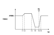
- FIG. FIG. 5 is a diagram showing a braking profile set by the braking control device as a transition of the target braking force when stopping the vehicle;
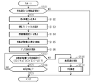
- 4 is a flow chart showing the flow of processing executed by the braking control device during braking;
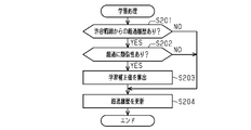
- 4 is a flowchart showing the flow of learning processing executed by the braking control device;
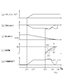
- 4 is a timing chart showing changes in braking force controlled by the braking control device;
- FIG. 4 is a timing chart showing changes in braking force controlled by the braking control device when an abnormality occurs;
- FIG. 10 is a timing chart showing changes in braking force controlled by the braking control device when pre-stop brake control is not performed;
- FIG. 1 shows a control device 10 as a vehicle braking control device and a vehicle 90 .
- a vehicle 90 includes a braking device 20 that applies braking force to wheels 91 .
- the control device 10 controls the braking device 20 .
- a vehicle 90 is equipped with a brake operation member 92 that can be operated by the driver.
- An example of the braking operation member 92 is a brake pedal.
- the vehicle 90 also includes a driving device that transmits driving force to the drive wheels of the wheels 91 .
- a driving device provided in vehicle 90 has an internal combustion engine as a power source.
- the power source of the driving device is not limited to the internal combustion engine.
- an electric motor may be mounted as a power source.
- the driving device one having an internal combustion engine and an electric motor as power sources may be employed.
- An in-wheel motor in which an electric motor as a power source is attached to each wheel 91 can also be used as a driving device.
- the braking device 20 is a friction braking device that generates frictional braking force.
- the braking device 20 may be a regenerative braking device that generates regenerative braking force.
- Vehicle 90 includes various sensors.
- FIG. 1 shows a wheel speed sensor 81 and a brake sensor 82 as examples of various sensors. Detection signals from various sensors are input to the control device 10 .
- the wheel speed sensor 81 is an example of a sensor capable of acquiring the rotation angle of the wheel 91.
- a wheel speed sensor 81 is provided for each wheel 91 .
- a detection signal from the wheel speed sensor 81 contains a pulse generated according to the rotation angle of the wheel 91 .
- a sensor that can acquire the rotation angle of the wheels 91 is a resolver included in the electric motor that transmits power to the drive wheels of the wheels 91 .
- the rotation angle of the electric motor can be obtained based on the signal output from the resolver. If the rotation angle of the electric motor can be obtained, the rotation angle of the wheels 91 can be obtained.
- the brake sensor 82 can detect the amount of operation of the braking operation member 92 .
- An example of the amount of operation of the braking operation member 92 is the pedal stroke BP as the amount of movement of the braking operation member 92 .
- the amount of operation of the brake operation member 92 can include a pedal effort as pressure applied to the brake operation member 92 to operate the brake operation member 92 .
- the control device 10 can calculate state quantities of the vehicle 90 based on detection signals from various sensors. For example, control device 10 can calculate the wheel speed, which is the rotational speed of wheel 91 , based on the detection signal from wheel speed sensor 81 . The control device 10 can calculate the vehicle body speed VS of the vehicle 90 based on the wheel speed. The control device 10 can calculate the pedal stroke BP as the amount of operation of the braking operation member 92 based on the detection signal from the brake sensor 82 .
- the control device 10 includes a braking control section 11, a first distance calculation section 12, a second distance calculation section 13, an abnormality determination section 14, and a learning section 15 as functional sections.
- the control device 10 may have any one of the following configurations [a] to [c]. [a] Equipped with one or more processors that execute various processes according to a computer program.
- a processor comprises a processing unit. Processing devices include CPUs, DSPs, GPUs, and the like.
- the processor includes memory.
- the memory stores program code or instructions configured to cause the processing unit to perform processes. Examples of memory include RAM, ROM, flash memory, and the like.
- Memory or computer-readable media includes any available media that can be accessed by a general purpose or special purpose computer.
- [b] includes one or more hardware circuits that perform various processes; Examples of hardware circuits include ASIC (Application Specific Integrated Circuit), CPLD (Complex Programmable Logic Device) and FPGA (Field Programmable Gate Array). [c] A processor that executes a part of various processes according to a computer program, and a hardware circuit that executes the rest of the various processes.
- ASIC Application Specific Integrated Circuit
- CPLD Computer Deformation Deformation
- FPGA Field Programmable Gate Array
- the braking control unit 11 can control the braking device 20.
- the braking control section 11 can calculate the reference braking force based on the pedal stroke BP.
- the reference braking force in this case corresponds to the magnitude of braking force requested by the driver of vehicle 90 .
- the braking control unit 11 can calculate the target braking force BFT based on the reference braking force.
- Target braking force BFT is used as a target value of the braking force to be applied to vehicle 90 by controlling braking device 20 .
- the braking control unit 11 sets a braking profile as transition of the target braking force BFT when stopping the vehicle 90 . Details of the braking profile will be described later.
- Braking control unit 11 can apply braking force to vehicle 90 by controlling braking device 20 based on target braking force BFT.
- the braking control unit 11 can calculate the distance traveled until the vehicle 90 stops while the vehicle 90 is being braked. Let the distance which the vehicle 90 moves until it stops be the stopping distance Ds. Calculation of the stopping distance Ds will be described.
- the braking control unit 11 can calculate the reference acceleration as a value obtained by estimating the longitudinal acceleration of the vehicle 90 on the assumption that the reference braking force is applied to the vehicle 90 .
- the reference acceleration is a value calculated such that the smaller the reference braking force, the smaller the value.
- the braking control unit 11 can estimate the position at which the vehicle 90 stops as the stop position based on the vehicle body speed VS and the reference acceleration while the vehicle 90 is being braked.
- the current position of the vehicle 90 at the time of estimation is set as the start position.
- the braking control unit 11 can calculate the distance from the start position to the stop position, that is, the distance traveled until the vehicle 90 stops, as the stop distance Ds.
- the braking control unit 11 can execute feedback control while the vehicle 90 is being braked. Through feedback control, the braking force can be adjusted when the vehicle body speed VS is small. Below, feedback control may be called "F/B control.” F/B control execution conditions will be described. As an example, the braking control unit 11 determines that the execution condition is met when the vehicle body speed VS becomes smaller than a prescribed threshold value. A judgment speed VSth for judging whether or not the vehicle body speed VS is very low can be used as the prescribed threshold value. The determination speed VSth is a value that is calculated and set in advance through experiments or the like.
- the determination speed VSth is a value that is less likely to deviate from the actual speed of the vehicle 90 and the vehicle speed VS calculated based on the detection signal from the wheel speed sensor 81 if the vehicle speed VS is equal to or higher than the determination speed VSth. is set.
- the braking control unit 11 adjusts the braking force based on the travel distance of the vehicle 90 during braking. Although the details will be described later, the braking control unit 11 increases or decreases the target braking force BFT so as to reduce the difference between the braking force reference distance and the wheel reference distance D.
- the braking force reference distance is the moving distance of the vehicle 90 that can be estimated from the braking force applied to the vehicle 90 .
- the wheel reference distance D is the movement distance of the vehicle 90 that can be estimated based on the distance that the vehicle 90 moves each time the wheels 91 rotate.
- the target braking force BFT after adjustment by F/B control can be determined by the target braking force BFT before adjustment, an increase/decrease according to the difference, and an increase/decrease based on a learning correction value described later.
- the braking control unit 11 may execute the pre-stop brake control while the vehicle 90 is being braked.
- the pre-stop brake control can be performed immediately before the vehicle 90 is stopped.
- the braking control unit 11 performs adjustment to increase or decrease the target braking force BFT with respect to the reference braking force corresponding to the pedal stroke BP.
- the pre-stop brake control it is possible to suppress the longitudinal acceleration fluctuation of the vehicle body and the change speed of the pitch angle when the vehicle 90 stops. Execution conditions for the pre-stop brake control will be described. As an example, the braking control unit 11 determines that the execution condition is satisfied when the vehicle body speed VS becomes smaller than the pre-stop speed.
- the braking control unit 11 determines that the execution condition is not satisfied when the target value of the longitudinal acceleration of the vehicle 90 is greater than a predetermined value toward the deceleration side even when the vehicle body speed VS is lower than the pre-stop speed.
- a predetermined value toward the deceleration side can also be An example of the pre-stop speed.
- the pre-stop speed is the same value as the determination speed VSth in the F/B control.
- a value different from the determination speed VSth can be adopted as the pre-stop speed.
- the braking control unit 11 can execute the F/B control while the pre-stop brake control is being executed.
- the first distance calculator 12 calculates the ideal distance transition Di used for F/B control.
- the first distance calculator 12 calculates the ideal distance transition Di when the condition for executing the F/B control is satisfied.
- the ideal distance transition Di indicates the transition until the movement distance of the vehicle 90 reaches the stop distance Ds.
- the first distance calculator 12 estimates the transition of the moving distance of the vehicle 90 over time when the braking force is applied according to the target braking force BFT, and calculates the ideal distance transition Di.
- the value of the ideal distance transition Di at the starting position is "0".
- the value of the ideal distance transition Di at the stop position is the stop distance Ds.
- a value at a certain time on the ideal distance transition Di indicates the distance between the position of the vehicle 90 and the starting position at that time.
- the value of the ideal distance transition Di corresponds to a braking force reference distance that is an estimated travel distance of the vehicle 90 until the vehicle 90 stops.
- the braking force reference distance is the moving distance of the vehicle 90 that can be estimated based on the estimated longitudinal acceleration when applying the braking force according to the target braking force BFT.
- a braking profile is set as the transition of the target braking force BFT. That is, when the pre-stop brake control is executed, the first distance calculation unit 12 calculates the braking force reference distance as the movement distance of the vehicle 90 reflecting the adjustment of the braking force by the pre-stop brake control.
- the first distance calculation unit 12 may set an allowable range for allowing the wheel reference distance D to deviate from the ideal distance transition Di as the ideal distance transition Di is calculated.
- the allowable range is set as a range from the lower limit value Dab to the upper limit value Daa.
- the first distance calculator 12 sets a value obtained by subtracting the lower width ⁇ from each value of the ideal distance transition Di as the lower limit value Dab.
- the first distance calculator 12 sets a value obtained by adding the upper width ⁇ to each value of the ideal distance transition Di as the upper limit value Daa.
- the lower width ⁇ and the upper width ⁇ may be the same value or different values. That is, the first distance calculator 12 can set an allowable range consisting of an upper limit value Daa and a lower limit value Dab that allows deviation from the braking force reference distance.
- the second distance calculation unit 13 calculates the wheel reference distance D used for F/B control.
- the second distance calculator 13 starts calculating the wheel reference distance D when the condition for executing the F/B control is satisfied.
- the second distance calculation unit 13 repeats the calculation of the wheel reference distance D at a predetermined cycle until the vehicle 90 stops, and updates the value.
- the second distance calculator 13 finishes calculating the wheel reference distance D when the vehicle 90 stops.
- the second distance calculator 13 can acquire pulses output from the wheel speed sensor 81 as the wheels 91 rotate as information indicating the rotation angle of the wheels 91 .
- the second distance calculator 13 can calculate the wheel reference distance D using the pulse that can be obtained by the wheel speed sensor 81 as the wheel 91 rotates and the diameter of the wheel 91 .
- the wheel reference distance D is obtained by calculating the movement distance per pulse and integrating the movement distance each time a pulse is generated.
- the travel distance per pulse can be calculated from the relationship between the distance traveled by the vehicle 90 as the wheels 91 rotate and the number of pulses generated while the wheels 91 rotate.
- the diameter of the wheel 91 is stored in the second distance calculator 13, for example.
- the second distance calculator 13 may store not only the diameter of the wheel 91 but also the outer circumference of the wheel 91 . Also, the moving distance per pulse may be stored. The second distance calculator 13 can also calculate the wheel reference distance D using the signal output from the resolver as information indicating the rotation angle of the wheels 91 .
- the abnormality determination unit 14 can determine whether the wheel reference distance D exceeds the allowable range during execution of the F/B control. The abnormality determination unit 14 determines that an abnormality has occurred when the wheel reference distance D exceeds the allowable range. The abnormality determination unit 14 determines that no abnormality has occurred when the wheel reference distance D is within the allowable range.
- the learning unit 15 can execute learning processing.
- the learning process is a process for suppressing repetition of the situation in which the wheel reference distance D exceeds the allowable range.
- the learning unit 15 can calculate a learning correction value for adjusting the target braking force BFT.
- the learning correction value is a value for correcting the target braking force BFT in order to suppress repetition of similar excesses.
- the learning correction value includes an amount for correcting the target braking force BFT and a timing for correcting the target braking force BFT.
- the learned correction value is calculated by the learning unit 15 as a value for increasing the target braking force BFT.
- the learning correction value can be calculated by the learning unit 15 as a value for decreasing the target braking force BFT.
- the initial value of the learning correction value is "0".
- the learning unit 15 can determine whether similar excesses occur repeatedly.
- the learning unit 15 may have a function of storing the situation in which the excess occurs for use in the determination.
- the learning unit 15 can store the determination result as a history.
- the learning unit 15 can store, as an excess history, various state quantities and various control quantities of the vehicle 90 when it is determined that an abnormality has occurred.
- the learning unit 15 can accumulate history until the excess history is initialized.
- the learning unit 15 can initialize the excess history and delete the determination result when the operation switch of the vehicle 90 is turned off.
- the learning unit 15 can also hold the excess history without initializing it even when the operation switch of the vehicle 90 is turned off.
- the learning unit 15 may return the learned correction value to the initial value when initializing the excess history.
- FIG. 2 shows a braking profile as a transition of the target braking force BFT.
- the timing t5 is when the vehicle 90 is stopped.
- a state in which the wheels 91 of the vehicle 90 stop rotating is referred to as the vehicle 90 being stopped.
- the period from timing t3 to timing t4 before timing t5 is the period during which the target braking force BFT is gradually decreased.
- the period from timing t4 to timing t5 is the period during which the target braking force BFT is kept constant.
- the amount of decrease in target braking force BFT per hour and the length of the period in which target braking force BFT is kept constant are adjusted according to vehicle body speed VS, longitudinal acceleration AS, stopping distance Ds, and the like.
- the target braking force BFT is increased after timing t5. This is to keep the vehicle 90 in a stopped state by suppressing movement of the vehicle 90 after stopping.
- the period from timing t5 to timing t6 is the period during which the target braking force BFT is increased to the reference braking force. After timing t6 when the target braking force BFT reaches the reference braking force, the target braking force BFT is maintained at the reference braking force. Note that it is not essential that the target braking force BFT after the increase coincides with the reference braking force as after timing t6.
- the braking control unit 11 reduces the difference in the braking distance compared to the case where the target braking force BFT is not reduced even if the target braking force BFT is reduced immediately before the vehicle 90 stops. do. Specifically, the braking control unit 11 temporarily increases the target braking force BFT before starting to decrease the target braking force BFT. In the profile set by the braking control unit 11, the period from the timing t1 before the timing t3 to the timing t2 is set as the period during which the target braking force BFT is gradually increased.
- the period from timing t2 to timing t3 is the period for maintaining the target braking force BFT constant.
- the braking control unit 11 calculates an increase amount and an increase period of the target braking force BFT, taking into account that the braking distance becomes shorter as the target braking force BFT is increased from the reference braking force. Then, the braking control unit 11 reflects the increase amount and the period during which the target braking force BFT is increased in the setting of the braking profile.
- the braking control unit 11 adjusts the control amount of the braking device 20 by changing the target braking force BFT according to the braking profile during execution of the pre-stop braking control. In the braking profile when the pre-stop brake control is not executed, the value of the reference braking force is set as the target braking force BFT.
- FIG. 3 shows the flow of processing executed by the control device 10 .
- This processing routine is started while the vehicle 90 is being braked.
- This processing routine can be repeatedly executed at predetermined intervals during braking.
- step S101 the control device 10 causes the braking control section 11 to determine whether or not the vehicle body speed VS is in a very low speed region.
- the braking control unit 11 determines that the vehicle body speed VS is in the very low speed region when the vehicle body speed VS is lower than the determination speed VSth. If the vehicle body speed VS is not in the very low speed region (S101: NO), the control device 10 once terminates this processing routine. On the other hand, when the vehicle body speed VS is in the very low speed region (S101: YES), the control device 10 shifts the processing to step S102.
- step S102 the control device 10 causes the braking control section 11 to calculate the stopping distance Ds.
- the braking control unit 11 estimates the stop position of the vehicle 90 and calculates the stop distance Ds. After that, the control device 10 shifts the process to step S103.
- the control device 10 causes the braking control section 11 to set a braking profile.
- the braking control unit 11 sets a braking profile in which the target braking force BFT is increased or decreased with respect to the reference braking force as illustrated in FIG.
- the braking control unit 11 sets a braking profile in which the value of the reference braking force is the target braking force BFT.
- step S104 the control device 10 causes the first distance calculator 12 to calculate the ideal distance transition Di.
- the first distance calculator 12 estimates the longitudinal acceleration of the vehicle 90 based on the braking profile set in the process of step S103, and calculates the ideal distance transition Di and the allowable range. In other words, the first distance calculator 12 calculates the braking force reference distance.
- the control device 10 shifts the process to step S105.
- step S105 the control device 10 causes the second distance calculator 13 to start calculating the wheel reference distance D.
- the second distance calculator 13 calculates the wheel reference distance D by setting the value at the time of starting the calculation to "0" and integrating the moving distance per pulse each time the pulse is detected. After that, the control device 10 shifts the process to step S106.
- step S106 the control device 10 causes the braking control section 11 to start F/B control.
- the braking control unit 11 increases or decreases the target braking force BFT set in the braking profile so as to reduce the difference between the braking force reference distance and the wheel reference distance D.
- the control device 10 shifts the process to step S107.
- step S107 the control device 10 causes the abnormality determination section 14 to determine whether the wheel reference distance D is within the allowable range.
- the abnormality determination unit 14 determines that the wheel reference distance D is within the allowable range.
- the wheel reference distance D is equal to or less than the lower limit value Dab, or when the wheel reference distance D is equal to or greater than the upper limit value Daa, it is determined that the wheel reference distance D exceeds the allowable range.
- step S107 if the wheel reference distance D is within the allowable range (S107: YES), the control device 10 shifts the process to step S108.
- step S108 the control device 10 causes the braking control section 11 to determine whether the vehicle 90 is stopped. For example, the braking control unit 11 can determine that the vehicle 90 has stopped when the wheel reference distance D has increased to the stopping distance Ds.
- step S107 If the vehicle 90 is stopped (S108: YES), the control device 10 ends this processing routine. On the other hand, when the vehicle 90 is not stopped (S108: NO), the control device 10 shifts the process to step S107 again. That is, until the vehicle 90 stops and the wheel reference distance D is within the allowable range, the processes of steps S107 and S108 are repeated.
- step S107 when the wheel reference distance D exceeds the allowable range, that is, when it is determined that an abnormality has occurred (S107: NO), the control device 10 advances the process to step S109. Transition.
- step S109 the control device 10 causes the braking control section 11 to perform degeneration control.
- Regression control is control that matches the target braking force BFT with the reference braking force. That is, the brake control unit 11 ends the pre-stop brake control and the F/B control after executing the degeneration control.
- the braking control unit 11 stops the vehicle 90 by controlling the braking device 20 based on the target braking force BFT equal to the reference braking force.
- the control device 10 shifts the process to step S110.
- control device 10 causes the learning unit 15 to perform learning processing. After that, the control device 10 terminates this processing routine. Details of the learning process will be described with reference to FIG.
- FIG. 4 shows a processing routine of learning processing executed by the learning unit 15 .
- This processing routine is started by the processing of step S110 in FIG. That is, the learning process is a process performed when the wheel reference distance D exceeds the allowable range.
- step S201 the learning unit 15 determines whether or not there is a history of the wheel reference distance D exceeding the allowable range. That is, it is determined whether or not the wheel reference distance D has exceeded the allowable range before the current exceeding of the allowable range. If there is no excess history (S201: NO), the learning unit 15 shifts the process to step S204. In step S204, the learning unit 15 stores the current situation in which the wheel reference distance D exceeds the allowable range, and updates the excess history. After that, the learning unit 15 terminates this processing routine.
- step S201 the learning unit 15 shifts the process to step S202.
- step S202 the learning unit 15 evaluates whether or not there is a similarity between the current excess from the allowable range and the stored excess history.
- the learning unit 15 refers to the excess history and evaluates that there is similarity when there are more than a specified number of histories in which the elapsed time until the wheel reference distance D exceeds the upper limit value Daa is close to the time Ti.
- the prescribed number of cases can be set to a value of two or more.
- the specified number of cases may be a value of one or more.
- step S202 If there is no similarity in exceeding the allowable range (S202: NO), the learning unit 15 shifts the process to step S204. After updating the excess history in step S204, the learning unit 15 terminates this processing routine.
- step S203 the learning unit 15 calculates a learning correction value.
- the braking control unit 11 adjusts the target braking force BFT during execution of the F/B control to a value reflecting the learning correction value.
- step S204 the learning unit 15 shifts the process to step S204. After updating the excess history in step S204, the learning unit 15 terminates this processing routine.
- FIG. 5 shows changes in the target braking force BFT when the vehicle 90 is stopped by braking.
- the pedal stroke BP increases from timing t11 as shown in FIG. 5(a).
- the pedal stroke BP is kept constant. Since the braking force is applied as the pedal stroke BP increases, the longitudinal acceleration AS takes a negative value during the period from timing t11 to timing t16 as shown in FIG. 5(b). Further, as the braking force is applied, the vehicle body speed VS decreases over time as shown in FIG. 5(c).
- the vehicle body speed VS is smaller than the determination speed VSth after timing t13. That is, in the example shown in FIG. 5, the period before timing t13 is a period in which deviation between the vehicle body speed VS and the actual speed of the vehicle 90 is unlikely to occur.
- F/B control is executed because the vehicle body speed VS is lower than the judgment speed VSth (S106). Furthermore, in the example shown in FIG. 5, the execution condition for the pre-stop brake control is established after timing t13. That is, after timing t13, pre-stop brake control is also executed.
- the example shown in FIG. 5 shows an example in which the vehicle 90 stops at timing t16. That is, the position of the vehicle 90 at timing t13 corresponds to the starting position. The position of vehicle 90 at timing t16 corresponds to the stop position.
- the target braking force BFT is indicated by a solid line. Further, after timing t13, the target braking force BFT when adjustment by F/B control is not performed is indicated by a dashed line.
- the target braking force BFT indicated by the dashed line is adjusted like the braking profile illustrated in FIG. 2 by executing the pre-stop brake control.
- a period from timing t13 to timing t14 is a period during which the target braking force BFT is increased from the reference braking force and a period during which the increased target braking force BFT is maintained.
- a period from timing t14 to timing t15 is a period in which the target braking force BFT is gradually decreased.
- a period from timing t15 to timing t16 is a period in which the target braking force BFT is kept constant. After timing t16, it is a period during which the target braking force BFT is increased to the reference braking force.
- the control device 10 by increasing or decreasing the target braking force BFT by the pre-stop brake control, the longitudinal acceleration just before the vehicle 90 stops, such as the period from the timing t14 to the timing t16 in (b) of FIG. AS can be brought closer to "0". Therefore, the amount of change in the longitudinal acceleration AS when the vehicle 90 stops can be kept small. As a result, it is possible to suppress the longitudinal acceleration fluctuation and the change speed of the pitch angle in the vehicle 90 .
- FIG. 5 shows the distance traveled by the vehicle 90 from the start position to the stop position.
- a dashed line indicates the ideal distance transition Di.
- a two-dot chain line indicates the lower limit value Dab and the upper limit value Daa. That is, the inside of the two double-dashed lines indicates the allowable range.
- the wheel reference distance D is indicated by a solid line.
- the ideal distance transition Di and the allowable range are calculated (S104).
- the ideal distance transition Di is "0" at timing t13.
- the ideal distance transition Di increases after timing t13 and reaches the stopping distance Ds at timing t16.
- the ideal distance transition Di transitions in a curved line reflecting the braking profile adjusted by the pre-stop brake control.
- the wheel reference distance D is calculated (S105). At the timing t13, the wheel reference distance D is "0".
- the controller 10 when the wheel reference distance D diverges from the ideal distance transition Di as shown in (d) and (e) of FIG. is incremented or decremented relative to the value of the damping profile indicated by the dashed line. As a result, the braking force applied to the vehicle 90 is increased or decreased.
- the longitudinal acceleration of the vehicle 90 may be affected depending on the inclination angle of the road surface. Due to such disturbances, the wheel reference distance D may deviate from the ideal distance transition Di. If the vehicle 90 continues to travel while the wheel reference distance D deviates from the ideal distance transition Di, the moving distance until the vehicle 90 stops may become shorter or longer than the stopping distance Ds.
- the target braking force BFT can be adjusted by the F/B control so as to reduce the difference between the wheel reference distance D and the ideal distance transition Di.
- the moving distance until the vehicle 90 stops can be matched with the stopping distance Ds. That is, the vehicle 90 can be stopped at the position calculated as the stop position.
- the dashed line shown in FIG. 5(b) shows the transition of the longitudinal acceleration AS when it is assumed that the braking force is applied according to the braking profile of the pre-stop brake control.
- the actual value of the longitudinal acceleration AS indicated by the solid line changes differently from the value indicated by the dashed line. This is because the braking force applied to the vehicle 90 is increased or decreased by the F/B control in addition to the pre-stop brake control.
- the dashed line shown in FIG. 5(c) shows the transition of the vehicle body speed VS when it is assumed that the braking force is applied according to the braking profile by the pre-stop brake control. showing.
- the value of the actual vehicle body speed VS indicated by the solid line changes differently from the value indicated by the dashed line. This is because the braking force applied to the vehicle 90 is increased or decreased by the F/B control in addition to the pre-stop brake control.
- the wheel reference distance D deviates from the ideal distance transition Di
- the wheel reference distance D does not exceed the allowable range.
- the travel distance of the vehicle 90 can be estimated based on the detection signal from the wheel speed sensor 81, and the braking force applied to the vehicle 90 can be controlled. That is, the braking force can be controlled without using the speed of the vehicle 90 calculated based on the detection signal from the wheel speed sensor 81 .
- the controller 10 calculates the wheel reference distance D by integrating the movement distance each time a pulse is generated, using the movement distance per pulse.
- the wheel reference distance D calculated in this way is compared with the speed, which is a value obtained by first-order differentiation of the rotation angle, and the acceleration, which is a value obtained by second-order differentiation of the rotation angle, the accuracy of the actual value can be reduced. Therefore, even if the accuracy of detecting the vehicle speed is low, the influence on the accuracy of controlling the braking force can be reduced.
- the control device 10 performs F/B control when the vehicle body speed VS is lower than the judgment speed VSth. By performing F/B control using the wheel reference distance D and the braking force reference distance in a region where the accuracy of calculating the vehicle body speed VS is low, the low accuracy of calculating the vehicle body speed VS can be compensated. .
- the distance traveled by the vehicle 90 to the stop position may be detected by a device such as a camera or radar.
- the control device 10 calculates the wheel reference distance D using the pulse obtained by the wheel speed sensor 81 as the wheel 91 rotates and the diameter of the wheel 91 . Therefore, according to the control device 10, even if the vehicle 90 is not equipped with a device such as a camera or radar, the distance traveled by the vehicle 90 to the stop position can be calculated. Further, even if the vehicle is equipped with a camera, it may not be possible to detect the distance traveled by the vehicle to the stop position if the camera is covered with snow or the like.
- the distance that the vehicle 90 moves to the stop position can be calculated even in a situation where a device such as a camera or radar cannot be used. can be done.
- the pedal stroke BP increases from timing t21. After timing t22, the pedal stroke BP is kept constant. As shown in FIG. 6B, the longitudinal acceleration AS takes a negative value during the period from timing t21 to timing t26. Further, as the braking force is applied, the vehicle body speed VS decreases over time as shown in FIG. 6(c). The vehicle body speed VS is smaller than the determination speed VSth after timing t23.
- the vehicle body speed VS is smaller than the judgment speed VSth, so feedback control is executed (S106). Furthermore, in the example shown in FIG. 6, pre-stop brake control is also executed after timing t23.
- the example shown in FIG. 6 shows an example in which the vehicle 90 stops at timing t26.
- the ideal distance transition Di and the allowable range are calculated (S104).
- the wheel reference distance D is calculated (S105).
- the ideal distance transition Di increases after timing t23 and reaches the stopping distance Ds at timing t25. That is, the braking profile is set such that the vehicle 90 reaches the stop position at the timing t25.
- the wheel reference distance D exceeds the upper limit value Daa in the allowable range. Therefore, it is determined that an abnormality has occurred at timing t24 (S107: NO), and degeneration control is being performed (S109). That is, after timing t24, the pre-stop brake control and the F/B control are terminated.
- the timing t24 is a period during which the target braking force BFT is decreased below the reference braking force as indicated by the dashed line in (e) of FIG. By executing the degeneracy control during this period, as indicated by the solid line, the reduction of the target braking force BFT is interrupted so that the target braking force BFT matches the reference braking force.
- an abnormality can be detected when the wheel reference distance D exceeds the allowable range.
- the wheel reference distance D exceeds the upper limit value Daa as in the example shown in FIG. indicates That is, there is a possibility that the braking force is insufficient.
- the target braking force BFT can be matched with the reference braking force by executing the degeneration control.
- the braking force required by the driver can be secured, and the shortage of braking force can be resolved.
- the vehicle 90 stops at a timing t26 that exceeds the timing t25 at which the vehicle 90 stops in the ideal distance transition Di. At this time, as indicated by the solid line in (d) of FIG. 6, the moving distance until the vehicle 90 stops is longer than the stopping distance Ds.
- the dashed line shown in FIG. 6(b) shows the transition of the longitudinal acceleration AS when it is assumed that the braking force is applied according to the braking profile of the pre-stop brake control.
- the actual value of the longitudinal acceleration AS indicated by the solid line is significantly different from the value indicated by the broken line after timing t24 when the degeneration control is performed. Since the pre-stop brake control has ended, the longitudinal acceleration AS immediately before the vehicle 90 stops does not approach "0.”
- the dashed line shown in FIG. 6(c) shows the transition of the vehicle body speed VS when it is assumed that the braking force is applied according to the braking profile of the pre-stop brake control. showing.
- the value of the actual vehicle body speed VS indicated by the solid line changes differently from the value indicated by the dashed line.
- the control device 10 can also detect an abnormality in which the wheel reference distance D exceeds the lower limit value Dab in the allowable range.
- the wheel reference distance D exceeds the lower limit value Dab, it indicates that the distance to the stop position is longer than when the vehicle 90 is traveling according to the ideal distance transition Di. That is, the braking force may be excessive.
- a situation in which the braking force becomes excessive may occur during a period in which the target braking force BFT is increased more than the reference braking force, such as the period from timing t1 to timing t3 in FIG.
- the control device 10 can perform the degeneracy control even when such an abnormality occurs. Excessive applied braking force can be reduced by matching the target braking force BFT with the reference braking force by executing the degeneration control.
- the control device 10 can perform learning processing when the wheel reference distance D exceeds the allowable range (S110). As a result, it is possible to store the history of the wheel reference distance D exceeding the allowable range (S204). Also, when similar excesses occur repeatedly, a learning correction value can be calculated (S203).
- the pedal stroke BP increases from timing t31 as shown in FIG. 7(a).
- the pedal stroke BP is kept constant. Since the braking force is applied as the pedal stroke BP increases, the longitudinal acceleration AS takes a negative value during the period from timing t31 to timing t34 as shown in FIG. 7(b). Further, as the braking force is applied, the vehicle body speed VS decreases over time as shown in FIG. 7(c). The vehicle body speed VS is smaller than the determination speed VSth after timing t33.
- the target braking force BFT is indicated by a solid line. Further, after timing t33, the target braking force BFT when adjustment by F/B control is not performed is indicated by a dashed line. In the example shown in FIG. 7, the pre-stop brake control is not executed, so the value of the reference braking force is used for the target braking force BFT indicated by the dashed line.
- FIG. 7 shows an example in which the vehicle 90 stops at timing t34. That is, the position of the vehicle 90 at timing t33 corresponds to the start position. The position of the vehicle 90 at timing t34 corresponds to the stop position.
- the ideal distance transition Di is indicated by a dashed line.
- the lower limit value Dab and the upper limit value Daa are indicated by two-dot chain lines. That is, the inside of the two double-dashed lines indicates the allowable range.
- the wheel reference distance D is indicated by a solid line.
- the ideal distance transition Di is "0" at timing t33 when the F/B control is started.
- the ideal distance transition Di increases after timing t33 and reaches the stopping distance Ds at timing t34.
- the ideal distance transition Di transitions as a straight line with a constant slope because the pedal stroke BP is constant. Further, the wheel reference distance D is "0" at timing t33 when the F/B control is started.
- the target braking force BFT indicated by the solid line is incremented or decremented relative to the value of the damping profile indicated by the dashed line. As a result, the braking force applied to the vehicle 90 is increased or decreased.
- the wheel reference distance D is a larger value than the ideal distance transition Di. This is a situation in which the longitudinal acceleration of vehicle 90 increases toward the positive value side due to, for example, the road surface on which vehicle 90 is running is downhill.
- F/B control is not performed, the vehicle 90 may exceed the stop position.
- the target braking force BFT can be adjusted by the F/B control so as to reduce the difference between the wheel reference distance D and the ideal distance transition Di.
- the target braking force BFT indicated by the solid line is made larger than the reference braking force indicated by the broken line.
- the moving distance until the vehicle 90 stops can be matched with the stopping distance Ds. That is, the vehicle 90 can be stopped at the position calculated as the stop position.
- the control device 10 can perform the F/B control even when the pre-stop brake control is not performed.
- step S109 in the above embodiment an example was described in which degeneration control is performed when the wheel reference distance D exceeds the allowable range, that is, when it is determined that an abnormality has occurred.
- the control to be executed when an abnormality occurs is not limited to this.
- the braking force may be increased from the value before the occurrence of the abnormality.
- the wheel reference distance D exceeds the allowable range due to, for example, the rotation of the wheels 91 being locked, it is possible to reduce the braking force.
- F/B control is not limited to pre-stop brake control, and can be executed together with control executed when vehicle body speed VS is in a very low speed region.
- the F/B control may be executed when the vehicle body speed VS is equal to or higher than the judgment speed VSth. That is, even when the vehicle body speed VS is equal to or higher than the determination speed VSth, the target braking force BFT may be adjusted so that the difference between the wheel reference distance D and the braking force reference distance becomes small.
- the reference braking force is calculated based on the pedal stroke BP, that is, the amount of operation of the braking operation member 92 has been described. That is, the case where the vehicle 90 is braked by the driver's operation has been described.
- the processing shown in FIGS. 3 and 4 can also be performed when the vehicle 90 is under automatic operation control.
- the reference braking force can be calculated by the automatic driving control device.
- the automatic driving control device may calculate the target braking force and the braking profile.
- the learning process is performed when the wheel reference distance D exceeds the allowable range. It is not essential to perform the learning process when an abnormality occurs.
- an example of calculating the learning correction value as the learning process was shown. As the learning process, learning may be performed such that F/B control is prohibited in situations where similar excesses are repeated.
Landscapes
- Engineering & Computer Science (AREA)
- Transportation (AREA)
- Mechanical Engineering (AREA)
- Regulating Braking Force (AREA)
Abstract
Description
図1は、車両の制動制御装置としての制御装置10と、車両90と、を示す。車両90は、車輪91に制動力を付与する制動装置20を備えている。制御装置10は、制動装置20を制御対象とする。車両90には、運転者による操作が可能な制動操作部材92が取り付けられている。制動操作部材92の一例は、ブレーキペダルである。また、車両90は、車輪91のうち駆動輪に駆動力を伝達する駆動装置を備えている。
車両90が備える駆動装置は、動力源としての内燃機関を有している。駆動装置が有する動力源は、内燃機関に限らない。たとえば、電動モータが動力源として搭載されていてもよい。駆動装置としては、内燃機関と電動モータとを動力源として備えているものを採用してもよい。動力源としての電動モータを各車輪91のホイールに取り付けたインホイールモータを駆動装置とすることもできる。
制動装置20の一例は、摩擦制動力を発生させる摩擦制動装置である。制動装置20は、回生制動力を発生させる回生制動装置でもよい。制動装置20としては、摩擦制動装置および回生制動装置によって摩擦制動力と回生制動力との協調制御を行うことのできる制動装置を採用することもできる。
車両90は、各種センサを備えている。図1には、各種センサの一例として、車輪速センサ81およびブレーキセンサ82を示している。各種センサからの検出信号は、制御装置10に入力される。
制御装置10は、各種センサからの検出信号に基づいて、車両90の状態量を算出することができる。たとえば、制御装置10は、車輪速センサ81からの検出信号に基づいて、車輪91の回転速度である車輪速度を算出することができる。制御装置10は、車輪速度に基づいて、車両90の車体速度VSを算出することができる。制御装置10は、ブレーキセンサ82からの検出信号に基づいて、制動操作部材92の操作量としてのペダルストロークBPを算出することができる。
制御装置10は、以下[a]~[c]のいずれかの構成であればよい。[a]コンピュータプログラムに従って各種処理を実行する一つ以上のプロセッサを備える。プロセッサは、処理装置を備える。処理装置としては、CPU、DSPおよびGPU等を挙げることができる。プロセッサは、メモリを備える。メモリは、処理を処理装置に実行させるように構成されたプログラムコードまたは指令を格納している。メモリとしては、RAM、ROMおよびフラッシュメモリ等を挙げることができる。メモリすなわちコンピュータ可読媒体は、汎用または専用のコンピュータでアクセスできるあらゆる利用可能な媒体を含む。[b]各種処理を実行する一つ以上のハードウェア回路を備える。ハードウェア回路の例は、ASIC(Application Specific Integrated Circuit)、CPLD(Complex Programmable Logic Device)およびFPGA(Field Programmable Gate Array)等がある。[c]各種処理の一部をコンピュータプログラムに従って実行するプロセッサと、各種処理のうち残りの処理を実行するハードウェア回路と、を備える。
図2を用いて、停止前ブレーキ制御における制動プロファイルの概要について説明する。図2は、目標制動力BFTの推移として制動プロファイルを示している。図2に示す例では、車両90を停止させる時がタイミングt5である。なお、車両90における車輪91の回転が止まっている状態のことを車両90が停止しているという。
図3は、制御装置10が実行する処理の流れを示す。本処理ルーチンは、車両90の制動中に開始される。本処理ルーチンは、制動中に所定の周期毎に繰り返し実行することができる。
図4は、学習部15が実行する学習処理の処理ルーチンを示す。本処理ルーチンは、図3におけるステップS110の処理によって開始される。すなわち、学習処理は、車輪基準距離Dが許容範囲を超過した場合に行われる処理である。
ステップS203では、学習部15は、学習補正値を算出する。この結果として、制動制御部11によって、F/B制御の実行中における目標制動力BFTが学習補正値を反映した値に調整される。学習部15は、学習補正値を算出すると、処理をステップS204に移行する。学習部15は、ステップS204において超過履歴を更新すると、本処理ルーチンを終了する。
本実施形態の作用および効果について説明する。
図5は、制動によって車両90が停止する際の目標制動力BFTの推移を示す。図5に示す例では、図5の(a)に示すようにタイミングt11からペダルストロークBPが増大している。タイミングt12以降では、ペダルストロークBPが一定に維持されている。ペダルストロークBPが増大することに伴って制動力が付与されるため、図5の(b)に示すようにタイミングt11からタイミングt16までの期間では、前後加速度ASが負の値となっている。また、制動力の付与に伴って、図5の(c)に示すように車体速度VSが時間の経過に伴って減少している。車体速度VSは、タイミングt13以降では判定速度VSthよりも小さくなっている。すなわち、図5に示す例では、タイミングt13よりも前の期間は、車体速度VSと実際の車両90の速度との乖離が発生しにくい期間である。
図7に示す例では、図7の(a)に示すようにタイミングt31からペダルストロークBPが増大している。タイミングt32以降では、ペダルストロークBPが一定に維持されている。ペダルストロークBPが増大することに伴って制動力が付与されるため、図7の(b)に示すようにタイミングt31からタイミングt34までの期間では、前後加速度ASが負の値となっている。また、制動力の付与に伴って、図7の(c)に示すように車体速度VSが時間の経過に伴って減少している。車体速度VSは、タイミングt33以降では判定速度VSthよりも小さくなっている。
本実施形態は、以下のように変更して実施することができる。本実施形態および以下の変更例は、技術的に矛盾しない範囲で互いに組み合わせて実施することができる。
・上記実施形態では、学習処理として学習補正値を算出する例を示した。学習処理としては、類似性のある超過が繰り返されるような状況ではF/B制御を禁止するような学習を行ってもよい。
Claims (5)
- 車輪の回転角を取得できるセンサを有する車両に適用される車両の制動制御装置であって、
前記車両の運転者による制動操作部材の操作量に対応する制動力を基準制動力として、該基準制動力が小さいほど値が小さくなるように推定される前記車両の前後加速度を用いて、前記車両が停止するまでの当該車両の移動距離を推定した制動力基準距離を前記前後加速度に基づいて算出する第1距離算出部と、
前記センサの検出信号と前記車輪の径とに基づいて前記車両の移動距離を推定した車輪基準距離を算出する第2距離算出部と、
前記制動力基準距離と前記車輪基準距離との差分が小さくなるように前記車両に付与する制動力を制御するフィードバック制御を実行する制動制御部と、を備える
車両の制動制御装置。 - 前記制動制御部は、前記車両の速度が規定のしきい値よりも小さい場合に、前記フィードバック制御を実行する
請求項1に記載の車両の制動制御装置。 - 前記第1距離算出部は、前記制動力基準距離に対しての乖離を許容する上限値および下限値からなる許容範囲を設定するものであり、
前記フィードバック制御の実行中に前記車輪基準距離が前記許容範囲を超過した場合には、異常が発生したと判定する異常判定部を備える
請求項1または請求項2に記載の車両の制動制御装置。 - 前記制動制御部は、前記異常判定部によって異常が発生していると判定されると、前記フィードバック制御を終了して、前記車両に付与する制動力を増加させる
請求項3に記載の車両の制動制御装置。 - 前記制動制御部は、前記車両に付与する制動力を前記基準制動力に対して調整して前記車両における車体の前後加速度変動とピッチ角の変化速度とを抑制する停止前ブレーキ制御を実行するものであり、該停止前ブレーキ制御の実行中に前記フィードバック制御を実行することができ、
前記第1距離算出部は、前記停止前ブレーキ制御が実行される際には、当該停止前ブレーキ制御による制動力の調整を反映した前記車両の移動距離として前記制動力基準距離を算出し、
前記制動制御部は、前記停止前ブレーキ制御の実行中に前記異常判定部によって異常が発生していると判定されると、前記停止前ブレーキ制御および前記フィードバック制御を終了して、前記基準制動力に基づいて前記車両に付与する制動力を制御する
請求項3に記載の車両の制動制御装置。
Priority Applications (3)
| Application Number | Priority Date | Filing Date | Title |
|---|---|---|---|
| US18/547,351 US12515627B2 (en) | 2021-03-29 | 2022-03-29 | Braking control device for vehicle |
| DE112022001815.1T DE112022001815T5 (de) | 2021-03-29 | 2022-03-29 | Bremssteuerungsvorrichtung für ein Fahrzeug |
| CN202280022944.1A CN117083210A (zh) | 2021-03-29 | 2022-03-29 | 车辆的制动控制装置 |
Applications Claiming Priority (2)
| Application Number | Priority Date | Filing Date | Title |
|---|---|---|---|
| JP2021055685A JP7484788B2 (ja) | 2021-03-29 | 2021-03-29 | 車両の制動制御装置 |
| JP2021-055685 | 2021-03-29 |
Publications (1)
| Publication Number | Publication Date |
|---|---|
| WO2022210751A1 true WO2022210751A1 (ja) | 2022-10-06 |
Family
ID=83456353
Family Applications (1)
| Application Number | Title | Priority Date | Filing Date |
|---|---|---|---|
| PCT/JP2022/015615 Ceased WO2022210751A1 (ja) | 2021-03-29 | 2022-03-29 | 車両の制動制御装置 |
Country Status (5)
| Country | Link |
|---|---|
| US (1) | US12515627B2 (ja) |
| JP (1) | JP7484788B2 (ja) |
| CN (1) | CN117083210A (ja) |
| DE (1) | DE112022001815T5 (ja) |
| WO (1) | WO2022210751A1 (ja) |
Families Citing this family (1)
| Publication number | Priority date | Publication date | Assignee | Title |
|---|---|---|---|---|
| JP2025025230A (ja) * | 2023-08-09 | 2025-02-21 | 株式会社デンソー | 移動量推定装置 |
Citations (3)
| Publication number | Priority date | Publication date | Assignee | Title |
|---|---|---|---|---|
| JPH09315282A (ja) * | 1996-05-27 | 1997-12-09 | Mitsubishi Electric Corp | アンチロックブレーキ制御装置 |
| EP3339117A1 (de) * | 2016-12-21 | 2018-06-27 | Karlsruher Institut für Technologie | Verfahren zur ansteuerung einer fahrzeugbremsanlage zur optimierung des bremsvorganges |
| JP2019151331A (ja) * | 2019-06-20 | 2019-09-12 | Ntn株式会社 | 電動ブレーキ装置 |
Family Cites Families (23)
| Publication number | Priority date | Publication date | Assignee | Title |
|---|---|---|---|---|
| JP3605421B2 (ja) * | 1994-01-26 | 2004-12-22 | 本田技研工業株式会社 | 推定車体速度算出方法 |
| JPH1170874A (ja) * | 1996-08-09 | 1999-03-16 | Denso Corp | 車両用ブレーキ装置 |
| JP3314686B2 (ja) * | 1997-09-18 | 2002-08-12 | トヨタ自動車株式会社 | 車両最短停止距離予測方法および車両最短停止距離予測装置 |
| US6847875B2 (en) * | 2003-02-26 | 2005-01-25 | Ford Global Technologies, Llc | Method for determining a longitudinal vehicle velocity by compensating individual wheel speeds |
| JP4148028B2 (ja) * | 2003-05-28 | 2008-09-10 | トヨタ自動車株式会社 | 車両走行制御装置 |
| US8086384B2 (en) * | 2006-01-06 | 2011-12-27 | Fuji Jukogyo Kabushiki Kaisha | Stop determination apparatus, inclination determination apparatus, and electric parking brake controller |
| DE102007003255A1 (de) * | 2006-01-24 | 2007-09-06 | The Yokohama Rubber Co., Ltd., Hiratsuka | Vorrichtung und Verfahren zum Vorhersagen eines Bremswegs eines Fahrzeugs |
| EP2147842A4 (en) * | 2007-04-17 | 2014-05-14 | Nissan Motor | DEVICE AND METHOD FOR ESTIMATING THE FRICTION CONDITION OF A GROUND CONTACT SURFACE OF A WHEEL |
| US8700281B2 (en) * | 2009-05-27 | 2014-04-15 | Toyota Jidosha Kabushiki Kaisha | Vehicle including a wheel stopping determination unit |
| WO2010146897A1 (ja) * | 2009-06-19 | 2010-12-23 | ボッシュ株式会社 | 車両用制動制御装置 |
| JP5455802B2 (ja) * | 2010-06-11 | 2014-03-26 | 日立建機株式会社 | 電動車両のピッチング制御装置 |
| JP5613597B2 (ja) * | 2011-03-16 | 2014-10-29 | 富士重工業株式会社 | 車両用運転支援装置 |
| WO2014016946A1 (ja) * | 2012-07-26 | 2014-01-30 | トヨタ自動車株式会社 | 制駆動力制御装置 |
| JP6177666B2 (ja) * | 2013-11-12 | 2017-08-09 | 日立オートモティブシステムズ株式会社 | 移動体の駆動制御装置 |
| JP2016028913A (ja) | 2014-07-25 | 2016-03-03 | 日産自動車株式会社 | 車両の前後振動制御装置 |
| US10023162B2 (en) * | 2014-09-05 | 2018-07-17 | Mitsubishi Electric Corporation | Automatic train operation system and brake control device |
| JP6380309B2 (ja) * | 2015-09-15 | 2018-08-29 | トヨタ自動車株式会社 | 車両の制御装置 |
| DE102016204136B4 (de) * | 2016-03-14 | 2018-07-12 | Ford Global Technologies, Llc | Verfahren und Vorrichtung zur automatisierten Längsbewegungssteuerung eines Kraftfahrzeugs |
| US10189453B2 (en) * | 2016-10-05 | 2019-01-29 | Toyota Motor Engineering & Manufacturing North America, Inc. | Coasting guidance timing and drive force adjustment |
| KR102507937B1 (ko) * | 2016-10-07 | 2023-03-10 | 주식회사 에이치엘클레무브 | 차량 제동 보조 장치 및 방법 |
| JP6442777B2 (ja) * | 2017-06-02 | 2018-12-26 | 本田技研工業株式会社 | 車両制御装置、車両制御方法、およびプログラム |
| JP6693483B2 (ja) * | 2017-07-26 | 2020-05-13 | 株式会社アドヴィックス | 車両の停止支援装置 |
| JP2020059367A (ja) * | 2018-10-09 | 2020-04-16 | トヨタ自動車株式会社 | 車両の制御装置 |
-
2021
- 2021-03-29 JP JP2021055685A patent/JP7484788B2/ja active Active
-
2022
- 2022-03-29 WO PCT/JP2022/015615 patent/WO2022210751A1/ja not_active Ceased
- 2022-03-29 DE DE112022001815.1T patent/DE112022001815T5/de active Pending
- 2022-03-29 CN CN202280022944.1A patent/CN117083210A/zh active Pending
- 2022-03-29 US US18/547,351 patent/US12515627B2/en active Active
Patent Citations (3)
| Publication number | Priority date | Publication date | Assignee | Title |
|---|---|---|---|---|
| JPH09315282A (ja) * | 1996-05-27 | 1997-12-09 | Mitsubishi Electric Corp | アンチロックブレーキ制御装置 |
| EP3339117A1 (de) * | 2016-12-21 | 2018-06-27 | Karlsruher Institut für Technologie | Verfahren zur ansteuerung einer fahrzeugbremsanlage zur optimierung des bremsvorganges |
| JP2019151331A (ja) * | 2019-06-20 | 2019-09-12 | Ntn株式会社 | 電動ブレーキ装置 |
Also Published As
| Publication number | Publication date |
|---|---|
| DE112022001815T5 (de) | 2024-01-04 |
| US20240132035A1 (en) | 2024-04-25 |
| US12515627B2 (en) | 2026-01-06 |
| JP2022152781A (ja) | 2022-10-12 |
| US20240227761A9 (en) | 2024-07-11 |
| JP7484788B2 (ja) | 2024-05-16 |
| CN117083210A (zh) | 2023-11-17 |
Similar Documents
| Publication | Publication Date | Title |
|---|---|---|
| US10073467B2 (en) | Vehicle traveling control apparatus | |
| JP2012025274A (ja) | 車両用制動支援装置及び車両用制動支援方法 | |
| US20050085985A1 (en) | Deceleration control apparatus and method for automotive vehicle | |
| US12466373B2 (en) | Method for controlling a braking torque of a vehicle during an at least partly automated traversal of an incline and/or a decline, computing device, and assistance system for a vehicle | |
| CN110550024A (zh) | 一种基于自动驾驶的车辆运行控制方法和装置 | |
| CN111497843A (zh) | 驾驶辅助系统及其制动控制单元和制动控制方法 | |
| EP2862765B1 (en) | Vehicle travel assistance device | |
| JP7484788B2 (ja) | 車両の制動制御装置 | |
| US10086669B2 (en) | Stabilizer control device | |
| US10981562B2 (en) | Vehicle stability control device | |
| US9188602B2 (en) | Acceleration detection device | |
| JP7413769B2 (ja) | 制動制御装置 | |
| WO2019004424A1 (ja) | 車両の制動制御装置 | |
| JP7574595B2 (ja) | 停車判定装置 | |
| US12409818B2 (en) | Control device | |
| JP2021054176A (ja) | 車両の制動制御装置 | |
| JP2016094112A (ja) | 車両の走行制御装置 | |
| US20220388513A1 (en) | Vehicle body speed estimation method and vehicle body speed estimation apparatus | |
| JP7230292B2 (ja) | 制動制御装置 | |
| WO2025116034A1 (ja) | 制動制御装置 | |
| JP6135662B2 (ja) | 車両用制動支援装置及び車両用制動支援方法 | |
| CN118220079A (zh) | 车辆制动控制方法、装置、车辆控制系统及车辆 | |
| WO2025121124A1 (ja) | 制動制御装置及び制動制御方法 | |
| CN119348705A (zh) | 一种车辆控制方法、系统及存储介质 | |
| JP2016078689A (ja) | 後輪操舵装置 |
Legal Events
| Date | Code | Title | Description |
|---|---|---|---|
| 121 | Ep: the epo has been informed by wipo that ep was designated in this application |
Ref document number: 22780962 Country of ref document: EP Kind code of ref document: A1 |
|
| WWE | Wipo information: entry into national phase |
Ref document number: 18547351 Country of ref document: US |
|
| WWE | Wipo information: entry into national phase |
Ref document number: 202280022944.1 Country of ref document: CN |
|
| WWE | Wipo information: entry into national phase |
Ref document number: 112022001815 Country of ref document: DE |
|
| 122 | Ep: pct application non-entry in european phase |
Ref document number: 22780962 Country of ref document: EP Kind code of ref document: A1 |
|
| WWG | Wipo information: grant in national office |
Ref document number: 18547351 Country of ref document: US |