WO2022210681A1 - チタン多孔質板材、および、水電解用電極、水電解装置 - Google Patents
チタン多孔質板材、および、水電解用電極、水電解装置 Download PDFInfo
- Publication number
- WO2022210681A1 WO2022210681A1 PCT/JP2022/015363 JP2022015363W WO2022210681A1 WO 2022210681 A1 WO2022210681 A1 WO 2022210681A1 JP 2022015363 W JP2022015363 W JP 2022015363W WO 2022210681 A1 WO2022210681 A1 WO 2022210681A1
- Authority
- WO
- WIPO (PCT)
- Prior art keywords
- layer
- titanium
- plate material
- water electrolysis
- porous plate
- Prior art date
- Legal status (The legal status is an assumption and is not a legal conclusion. Google has not performed a legal analysis and makes no representation as to the accuracy of the status listed.)
- Ceased
Links
Images


Classifications
-
- B—PERFORMING OPERATIONS; TRANSPORTING
- B22—CASTING; POWDER METALLURGY
- B22F—WORKING METALLIC POWDER; MANUFACTURE OF ARTICLES FROM METALLIC POWDER; MAKING METALLIC POWDER; APPARATUS OR DEVICES SPECIALLY ADAPTED FOR METALLIC POWDER
- B22F3/00—Manufacture of workpieces or articles from metallic powder characterised by the manner of compacting or sintering; Apparatus specially adapted therefor ; Presses and furnaces
- B22F3/10—Sintering only
- B22F3/11—Making porous workpieces or articles
-
- B—PERFORMING OPERATIONS; TRANSPORTING
- B22—CASTING; POWDER METALLURGY
- B22F—WORKING METALLIC POWDER; MANUFACTURE OF ARTICLES FROM METALLIC POWDER; MAKING METALLIC POWDER; APPARATUS OR DEVICES SPECIALLY ADAPTED FOR METALLIC POWDER
- B22F5/00—Manufacture of workpieces or articles from metallic powder characterised by the special shape of the product
-
- B—PERFORMING OPERATIONS; TRANSPORTING
- B22—CASTING; POWDER METALLURGY
- B22F—WORKING METALLIC POWDER; MANUFACTURE OF ARTICLES FROM METALLIC POWDER; MAKING METALLIC POWDER; APPARATUS OR DEVICES SPECIALLY ADAPTED FOR METALLIC POWDER
- B22F7/00—Manufacture of composite layers, workpieces, or articles, comprising metallic powder, by sintering the powder, with or without compacting wherein at least one part is obtained by sintering or compression
- B22F7/02—Manufacture of composite layers, workpieces, or articles, comprising metallic powder, by sintering the powder, with or without compacting wherein at least one part is obtained by sintering or compression of composite layers
-
- C—CHEMISTRY; METALLURGY
- C22—METALLURGY; FERROUS OR NON-FERROUS ALLOYS; TREATMENT OF ALLOYS OR NON-FERROUS METALS
- C22C—ALLOYS
- C22C1/00—Making non-ferrous alloys
- C22C1/08—Alloys with open or closed pores
-
- C—CHEMISTRY; METALLURGY
- C25—ELECTROLYTIC OR ELECTROPHORETIC PROCESSES; APPARATUS THEREFOR
- C25B—ELECTROLYTIC OR ELECTROPHORETIC PROCESSES FOR THE PRODUCTION OF COMPOUNDS OR NON-METALS; APPARATUS THEREFOR
- C25B11/00—Electrodes; Manufacture thereof not otherwise provided for
- C25B11/02—Electrodes; Manufacture thereof not otherwise provided for characterised by shape or form
- C25B11/03—Electrodes; Manufacture thereof not otherwise provided for characterised by shape or form perforated or foraminous
- C25B11/031—Porous electrodes
- C25B11/032—Gas diffusion electrodes
-
- C—CHEMISTRY; METALLURGY
- C25—ELECTROLYTIC OR ELECTROPHORETIC PROCESSES; APPARATUS THEREFOR
- C25B—ELECTROLYTIC OR ELECTROPHORETIC PROCESSES FOR THE PRODUCTION OF COMPOUNDS OR NON-METALS; APPARATUS THEREFOR
- C25B9/00—Cells or assemblies of cells; Constructional parts of cells; Assemblies of constructional parts, e.g. electrode-diaphragm assemblies; Process-related cell features
-
- H—ELECTRICITY
- H01—ELECTRIC ELEMENTS
- H01M—PROCESSES OR MEANS, e.g. BATTERIES, FOR THE DIRECT CONVERSION OF CHEMICAL ENERGY INTO ELECTRICAL ENERGY
- H01M4/00—Electrodes
- H01M4/86—Inert electrodes with catalytic activity, e.g. for fuel cells
-
- H—ELECTRICITY
- H01—ELECTRIC ELEMENTS
- H01M—PROCESSES OR MEANS, e.g. BATTERIES, FOR THE DIRECT CONVERSION OF CHEMICAL ENERGY INTO ELECTRICAL ENERGY
- H01M8/00—Fuel cells; Manufacture thereof
- H01M8/10—Fuel cells with solid electrolytes
Definitions
- the present invention relates to a titanium porous plate material which is excellent in flowability of fluids such as liquids and gases and which is excellent in contact with other members, and a water electrolysis electrode and a water electrolysis device comprising the titanium porous plate material. It is about.
- This application claims priority based on Japanese Patent Application No. 2021-054472 filed in Japan on March 29, 2021, the content of which is incorporated herein.
- Water electrolyzers are attracting attention as candidates for hydrogen production technology, and there are several types of water electrolyzers such as solid oxide water electrolyzers (SOEC) and alkaline water electrolyzers.
- SOEC solid oxide water electrolyzers
- PEM type solid polymer type water electrolyzers have the advantage of being able to operate at about 100° C. and having high electrolysis efficiency and hydrogen purity at the time of generation.
- the internal structure and members of the solid polymer type water electrolysis cell are, for example, current collector (Au-plated SUS plate, etc.)/gas diffusion layer (electrode): porous carbon/catalyst layer (Pt/C + ionomer) from the cathode side. )/ion exchange membrane (polymer material)/catalyst layer (Ir particles + ionomer)/gas diffusion layer (electrode): titanium porous body/collector plate (Au-plated SUS plate, etc.).
- the gas diffusion layer described above is often called a GDL (gas diffusion layer), but it is also called an electrode because it plays a role of conducting current to the catalyst layer, which is the reaction site of the water electrolysis reaction.
- the properties required for the gas diffusion layer (electrode) on the anode side are (1) the need to diffuse oxygen gas after water electrolysis and the liquid water of the raw material, and (2) the severe corrosion environment during electrolysis. There is no corrosion. Therefore, a titanium material having excellent corrosion resistance is used for the gas diffusion layer (electrode) on the anode side.
- titanium materials used as electrodes include a titanium sintered body disclosed in Patent Document 1 and a titanium foam material disclosed in Patent Document 2.
- a titanium sintered body disclosed in Patent Document 1 and a titanium foam material disclosed in Patent Document 2.
- porous electrodes composed of two layers of a sheet and a sponge have been proposed in order to increase power generation efficiency. .
- Japanese Patent No. 6485967 Japanese Patent Application Laid-Open No. 2006-138005 (A) Japanese Patent No. 3982356 (B) Japanese special table 2020-524747 (A)
- Patent Document 1 In the titanium sintered body described in the above-mentioned Patent Document 1, the porosity cannot be sufficiently increased. oxygen gas could not be sufficiently diffused, and the electrolysis efficiency could not be improved.
- the titanium foam material described in Patent Document 2 has a high porosity, when it is used as an electrode of a cell for water electrolysis, it is not possible to secure a contact area with the catalyst, and the electrolysis efficiency cannot be improved. I could not.
- Patent Documents 3 and 4 do not disclose a two-layer electrode made of a titanium material, and its corrosion resistance is insufficient, so it could not be used as an electrode for a water electrolysis cell.
- the present invention has been made against the background of the circumstances as described above, and is capable of sufficiently contacting other adjacent members and allowing fluids such as liquids and gases to be well circulated and diffused. It is an object of the present invention to provide a porous titanium plate material capable of achieving the above-mentioned properties, and an electrode for water electrolysis and a water electrolysis device made of this porous titanium plate material.
- the porous titanium plate material of the present invention is a porous titanium plate material comprising a sintered body of titanium or a titanium alloy, wherein the porous titanium plate material is
- the titanium porous plate has a three-dimensional network structure having communicating pores that are open on the surface and communicate with the internal pores, and the titanium porous plate has a first layer and a second layer having a thickness. It is characterized in that the second layer has an average pore diameter larger than that of the first layer.
- the first layer and the second layer having a larger average pore diameter than the first layer are laminated in the thickness direction.
- a contact area with other adjacent members can be ensured by the first layer having a small .
- the second layer having an average pore diameter larger than that of the first layer is laminated, it becomes possible to distribute and diffuse fluid such as liquid and gas satisfactorily.
- the average pore diameter of the first layer is 10 ⁇ m or less. In this case, since the average pore diameter of the first layer is limited to 10 ⁇ m or less, a sufficient contact area with other adjacent members can be ensured.
- the average pore diameter of the second layer is in the range of 50 ⁇ m or more and 600 ⁇ m or less.
- the average pore diameter of the second layer is set to be relatively large, from 50 ⁇ m to 600 ⁇ m, it is possible to allow fluid such as liquid and gas to flow well and diffuse sufficiently.
- the porosity of the first layer is preferably in the range of 30% or more and 70% or less. In this case, since the porosity of the first layer is in the range of 30% or more and 70% or less, a sufficient contact area with other adjacent members can be ensured.
- the porosity of the second layer is preferably in the range of 75% or more and 95% or less.
- the porosity of the second layer is set within the range of 75% or more and 95% or less, it is possible to allow fluid such as liquid and gas to flow well and diffuse sufficiently.
- the ratio t1/t2 between the thickness t1 of the first layer and the thickness t2 of the second layer is in the range of 0.01 to 1.0. is preferred.
- the ratio t1/t2 between the thickness t1 of the first layer and the thickness t2 of the second layer is in the range of 0.01 or more and 1.0 or less, Good contact with the member can be obtained, and fluid such as liquid and gas can be well circulated and sufficiently diffused in the second layer.
- the electrode for water electrolysis of the present invention is characterized by being made of the titanium porous plate material described above. According to the electrode for water electrolysis having this configuration, since it is composed of the above-described porous titanium plate material, the contact area with the catalyst layer is secured by arranging the first layer on the catalyst layer side, and the efficiency of using the catalyst is increased. is improved, and the fluid such as liquid or gas is well circulated and sufficiently diffused in the second layer, so that water can be electrolyzed efficiently and stably.
- a water electrolysis apparatus of the present invention is characterized by including the above-described electrode for water electrolysis.
- the electrode for water electrolysis having this configuration, since the electrode for water electrolysis is made of the above-described porous titanium plate material, the contact area with the catalyst layer can be reduced by arranging the first layer on the side of the catalyst layer.
- a titanium porous plate material that can be brought into sufficient contact with other adjacent members and that allows fluid such as liquid and gas to flow and diffuse well, and this titanium porous plate material. It is possible to provide an electrode for water electrolysis and a water electrolysis device made of a solid plate material.
- FIG. 1 is an explanatory diagram showing an example of a porous titanium plate material that is an embodiment of the present invention
- FIG. 2 is a flowchart showing an example of a method for manufacturing the porous titanium plate material shown in FIG. 1
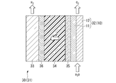
- BRIEF DESCRIPTION OF THE DRAWINGS It is a schematic explanatory drawing of the water electrolysis apparatus which is embodiment of this invention.
- porous titanium plate material the electrode for water electrolysis, and the water electrolysis apparatus, which are embodiments of the present invention, will be described with reference to the attached drawings.
- the titanium porous plate material 10 of the present embodiment is used, for example, as a current-carrying member such as a cathode electrode of a polymer electrolyte fuel cell (PEFC), an anode electrode of a water electrolysis device, an electrode material for a lithium-ion battery or a lithium-ion capacitor. It is what is done. In this embodiment, as will be described later, it is used as an electrode forming a gas diffusion layer (GDL) of the water electrolysis device (water electrolysis device) shown in FIG.
- GDL gas diffusion layer
- the titanium porous plate material 10 of this embodiment has a three-dimensional network structure having open pores on the surface and communicating with internal pores.
- the porous titanium plate 10 of this embodiment has a structure in which a first layer 11 and a second layer 12 having a larger average pore diameter than the first layer 11 are laminated in the thickness direction. .
- the average pore diameter of the first layer 11 is 10 ⁇ m or less.
- the average pore diameter of the second layer 12 is preferably in the range of 50 ⁇ m or more and 600 ⁇ m or less.
- the average pore diameters of the first layer 11 and the second layer 12 were equivalent circle diameters (diameters) determined from the cross-sectional areas of pores observed in X-ray CT images.
- the porosity of the first layer 11 is preferably in the range of 30% or more and 70% or less.
- the porosity of the second layer 12 is preferably in the range of 75% or less and 95% or less.
- the porosities of the first layer 11 and the second layer 12 can be calculated from X-ray CT images and weights.
- the ratio t1/t2 between the thickness t1 of the first layer 11 and the thickness t2 of the second layer 12 is in the range of 0.01 to 1.0. preferable.
- the laminated structure, the average pore size of the first layer 11 and the second layer 12, the porosity of the first layer 11 and the second layer 12, and the porosity of the first layer 11 are described below.
- the reason why the ratio between the thickness t1 and the thickness t2 of the second layer 12 is defined as above will be explained.
- the porous titanium plate 10 of the present embodiment has a structure in which the first layer 11 and the second layer 12 having different average pore diameters are laminated in the thickness direction.
- the first layer 11 having a small average pore diameter it is possible to secure a contact area with other adjacent members.
- the second layer 12 having a large average pore diameter the circulation of liquid and gas is promoted. Therefore, in the porous titanium plate material 10 of the present embodiment, it is possible to secure a contact area with other adjacent members and promote diffusion of liquids and gases.
- the average pore size of the first layer 11 is preferably 10 ⁇ m or less.
- the upper limit of the average pore size of the first layer 11 is more preferably 9 ⁇ m or less, more preferably 8 ⁇ m or less.
- the lower limit of the average pore diameter of the first layer 11 is preferably 0.1 ⁇ m or more, more preferably 0.2 ⁇ m or more.
- the average pore diameter of the second layer 12 is preferably in the range of 50 ⁇ m or more and 600 ⁇ m or less.
- the lower limit of the average pore diameter of the second layer 12 is more preferably 75 ⁇ m or more, more preferably 100 ⁇ m or more.
- the upper limit of the average pore size of the second layer 12 is more preferably 550 ⁇ m or less, more preferably 500 ⁇ m or less.
- the porosity of the first layer 11 when the porosity of the first layer 11 is 30% or more, the first layer 11 can sufficiently ensure the flow of liquid and gas.
- the porosity of the first layer 11 when the porosity of the first layer 11 is 70% or less, it is possible to secure a sufficient contact area with other adjacent members. Therefore, in the present embodiment, the porosity of the first layer 11 is preferably within the range of 30% or more and 70% or less.
- the lower limit of the porosity of the first layer 11 is more preferably 35% or higher, more preferably 40% or higher.
- the upper limit of the porosity of the first layer 11 is more preferably 65% or less, more preferably 60% or less.
- the porosity of the second layer 12 is preferably within the range of 75% or more and 95% or less.
- the lower limit of the porosity of the second layer 12 is more preferably 77% or higher, more preferably 79% or higher.
- the upper limit of the porosity of the second layer 12 is more preferably 93% or less, more preferably 90% or less.
- the first layer 11 thickness is ensured, and a sufficient contact area with other adjacent members can be ensured. Moreover, the strength of the titanium porous plate 10 as a whole can be ensured, and the handleability is improved.
- the ratio t1/t2 between the thickness t1 of the first layer 11 and the thickness t2 of the second layer 12 is 1.0 or less, the thickness of the second layer 12 is ensured and liquid or gas can be distributed well.
- the ratio t1/t2 between the thickness t1 of the first layer 11 and the thickness t2 of the second layer 12 is preferably in the range of 0.01 to 1.0.
- the lower limit of the ratio t1/t2 between the thickness t1 of the first layer 11 and the thickness t2 of the second layer 12 is more preferably 0.05 or more, more preferably 0.1 or more.
- the upper limit of the ratio t1/t2 between the thickness t1 of the first layer 11 and the thickness t2 of the second layer 12 is more preferably 0.9 or less, more preferably 0.8 or less. .
- titanium powder made of titanium or a titanium alloy is prepared as raw material powder.
- titanium hydride powder or pure titanium powder produced by dehydrogenating titanium hydride powder was prepared.
- This raw material powder contains a water-soluble resin binder (methyl cellulose), organic solvents (neopentane, hexane and butane), plasticizers (glycerin and ethylene glycol), water as a solvent, and optionally a surfactant (alkylbenzene sulfonate). are mixed to prepare a first titanium-containing slurry that will be the first layer 11 .
- the raw material powder described above contains a water-soluble resin binder (methyl cellulose), organic solvents (neopentane, hexane and butane), plasticizers (glycerin and ethylene glycol), water as a solvent, and in some cases a surfactant (alkylbenzene sulfone). acid salt), and a foaming agent are added to prepare a second titanium-containing slurry that will become the second layer 12 .
- a water-soluble resin binder methyl cellulose
- organic solvents neopentane, hexane and butane
- plasticizers glycerin and ethylene glycol
- water water as a solvent
- a surfactant alkylbenzene sulfone
- acid salt alkylbenzene sulfone
- Step S03 Next, while being placed on the zirconia plate, it is fed into a high-temperature and high-humidity tank, where it is held at a predetermined temperature and humidity to foam and then dried with warm air to obtain a laminated green sheet molded body. .
- the titanium porous plate material 10 of the present embodiment is manufactured by the manufacturing method described above.
- FIG. 3 shows a schematic diagram of the electrode for water electrolysis and the water electrolysis apparatus of this embodiment.
- the water electrolyzer of the present embodiment is a solid polymer type water splitter with high electrolysis efficiency and high hydrogen purity at the time of generation.
- the water electrolysis device 30 of the present embodiment comprises an anode 32 and a cathode 33 facing each other, and an ion permeable membrane 34 arranged between the anode 32 and the cathode 33. is provided with a water electrolysis cell 31.
- Catalyst layers 35 and 36 are formed on both surfaces of the ion permeable membrane 34 (the contact surface with the anode 32 and the contact surface with the cathode 33), respectively.
- the cathode electrode 33, the ion permeable membrane 34, and the catalyst layers 35 and 36 those used in a conventional general solid polymer type water electrolysis apparatus can be applied.
- the above anode electrode 32 is the electrode for water electrolysis according to the present embodiment.
- the anode 32 (electrode for water electrolysis) is composed of the titanium porous plate material 10 of the present embodiment described above.
- the anode 32 (electrode for water electrolysis) is arranged so that the first layer 11 faces the catalyst layer 35 side.
- Oxygen (O 2 ) generated by electrolysis of water is then discharged from the anode 32 and hydrogen (H 2 ) is discharged from the cathode 33 .
- the anode electrode 32 since water (liquid) and oxygen (gas) flow through the anode 32 as described above, it must have a high porosity in order to stably flow these liquids and gases. is preferred. Further, in the anode electrode 32, contact with the catalyst layer 35 accelerates the reaction, so it is preferable to secure a contact area with the catalyst layer 35. FIG. Furthermore, since the anode electrode 32 is exposed to oxygen, excellent corrosion resistance is required. Therefore, the electrode for water electrolysis made of the titanium porous plate material 10 of the present embodiment is particularly suitable as the anode electrode 32 .
- the first layer 11 and the second layer 12 having different average pore diameters are laminated in the thickness direction, and the second layer 12 is larger than the average pore diameter of the first layer 11, the first layer 11 having a small average pore diameter can ensure a contact area with another adjacent member (catalyst layer 35). can.
- the second layer 12 having a large average pore diameter enables good circulation and diffusion of fluid such as liquid and gas.
- the average pore diameter of the first layer 11 when the average pore diameter of the first layer 11 is 10 ⁇ m or less, a sufficient contact area with another adjacent member (catalyst layer 35) must be ensured. can be done.
- the average pore diameter of the second layer 12 when the average pore diameter of the second layer 12 is within the range of 50 ⁇ m or more and 600 ⁇ m or less, the average pore diameter of the second layer 12 is set relatively large. Therefore, the fluid such as liquid and gas can be well circulated and sufficiently diffused.
- the contact area with another adjacent member (catalyst layer 35) is can be sufficiently secured.
- the porosity of the second layer 12 when the porosity of the second layer 12 is within the range of 75% or more and 95% or less, fluid such as liquid and gas can be well circulated and sufficiently diffused. It is possible to
- the ratio t1/t2 between the thickness t1 of the first layer 11 and the thickness t2 of the second layer 12 is within the range of 0.01 or more and 1.0 or less
- the first layer 11 allows good contact with other members
- the second layer 12 allows fluid such as liquid and gas to flow well and diffuse sufficiently.
- the electrode for water electrolysis is composed of the above-described porous titanium plate 10 and is used as the anode 32. Therefore, by arranging the first layer 11 on the catalyst layer 35 side, The contact area is secured to improve the use efficiency of the catalyst, and the fluid such as liquid and gas is well distributed and sufficiently diffused in the second layer 12, so that the electrolysis of water is efficiently and stably performed. It is possible to do
- the water electrolysis electrode made of the titanium porous plate 10 described above is used as the anode 32, so that the efficiency of using the catalyst is excellent, and liquids, gases, etc. can be well circulated and sufficiently diffused, and water electrolysis can be performed efficiently and stably.
- the present invention is not limited to this, and can be modified as appropriate without departing from the technical idea of the invention.
- the water electrolysis device water electrolysis cell
- a water electrolysis device water electrolysis cell having another structure may be used as long as it has electrodes for water electrolysis.
- the titanium porous plate material of the present invention may be used for applications other than the water electrolysis device.
- porous titanium plates were manufactured according to the procedure described in the embodiment section.
- a titanium hydride powder with an average particle size of 15 ⁇ m and a pure titanium powder with an average particle size of 10 ⁇ m were prepared.
- methylcellulose is prepared as a water-soluble resin binder
- neopentane, hexane and butane are prepared as organic solvents
- glycerin and ethylene glycol are prepared as plasticizers
- water is prepared as a solvent
- alkylbenzene sulfone is prepared as a surfactant.
- An acid salt was prepared.
- titanium hydride powder methyl cellulose as a water-soluble resin binder, neopentane, hexane and heptane as organic solvents, glycerin and ethylene glycol as plasticizers, and water as a solvent are blended, and if necessary, the interface Alkylbenzenesulfonate as an activator was added and kneaded for 15 minutes to prepare a first titanium-containing slurry.
- Second titanium-containing slurries with different mixing ratios of raw material powder, foaming agent, plasticizer and solvent were prepared by the same procedure as above.
- a first slurry layer was formed on a zirconia plate by a doctor blade method with a blade gap of 0.4 mm.
- the second slurry layer was laminated on the first slurry layer by the above-described doctor blade method to form a laminated sheet compact.
- This laminated sheet molded product placed on the zirconia plate is supplied to a high-temperature/high-humidity tank, where it is foamed under the conditions of temperature: 40°C, humidity: 90%, and held for 20 minutes, and then temperature: 80°C. , and hot air drying under the condition of holding for 15 minutes to prepare a laminated green sheet compact.
- This laminated green sheet compact was degreased and sintered at 1170° C. for 10 hours to obtain a titanium porous plate material.
- Example 6 of the present invention a titanium sheet material produced using a titanium-containing slurry, a titanium fiber sintered body obtained by sintering titanium fibers, and a zirconia plate were stacked and placed at 1000 ° C. and 10 Diffusion bonding was performed under a vacuum atmosphere for a time retention.
- Comparative Example 1 a single layer of titanium fiber sintered body was used, and in Comparative Examples 2 and 3, a single layer of titanium sheet material was used.
- the titanium porous plate materials of Inventive Examples 1-6 and Comparative Examples 1-3 were evaluated for the following items. Table 1 shows the evaluation results.
- a sample for cross-sectional observation was taken from the titanium porous plate described above, and a cross-sectional observation image of the sample was taken by X-ray fluoroscopic measurement. The circle equivalent diameter (diameter) was calculated from the observed pore area.
- Porosity A sample for cross-sectional observation was taken from the titanium porous plate material described above, and a three-dimensional cross-sectional observation image of the sample was taken by X-ray fluoroscopic measurement. Regarding the second layer 12 having an average pore diameter of 50 ⁇ m or more, the skeleton portion and the pore portion were classified by binarization processing from the three-dimensional cross-sectional observation image, and the porosity (P2) and volume V2 were calculated. On the other hand, the porosity (P1) of the first layer 11 having a small pore diameter was calculated by the following formula.
- W1 Mass (g) of 11 parts of the first layer of the titanium porous plate material 10
- V1 Volume (cm3) of 11 parts of the first layer of the titanium porous plate material 10
- DT true density (g/cm3) of titanium constituting the titanium porous plate material 10
- W1 was calculated by the following formula using the mass Wa of the titanium porous plate material 10 measured by an electronic balance and the above V2.
- W1 Wa-V2 ⁇ (1-P2) ⁇ DT Wa: Mass (g) of titanium porous plate material 10 V2: Volume of 12 parts of the second layer of the porous titanium plate 10 (cm3)
- P2 porosity of second layer 12 of titanium porous plate 10
- Electrolytic efficiency Using the titanium substrates described above as anodes, a solid polymer type water electrolysis cell (area 4 cm ⁇ 4 cm) having the structure shown in FIG. 3 was constructed. With pure water supplied to the anode, a voltage of 2.5 V was applied between the anode and the cathode of the water electrolysis cell, the current density flowing through the cell due to water electrolysis was measured, and the electrolysis efficiency ratio was calculated from the ratio. The test temperature was set at 80°C.
- the porous titanium plate material of Example 1-6 of the present invention having a laminated structure of the first layer and the second layer having different average pore diameters
- the porous titanium plate material of Comparative Example 1-3 having a single-phase structure It was confirmed that the electrolysis efficiency was improved compared to
- the titanium porous plate material can be brought into sufficient contact with other adjacent members, and can allow fluids such as liquids and gases to be well circulated and diffused. It was confirmed that it is possible to provide
- the present invention provides a titanium porous plate material that can be brought into sufficient contact with other adjacent members and that allows fluids such as liquids and gases to flow and diffuse well, and this titanium porous plate material. It is possible to provide a water electrolysis electrode and a water electrolysis device consisting of.
Landscapes
- Chemical & Material Sciences (AREA)
- Engineering & Computer Science (AREA)
- Chemical Kinetics & Catalysis (AREA)
- Materials Engineering (AREA)
- Mechanical Engineering (AREA)
- Manufacturing & Machinery (AREA)
- Electrochemistry (AREA)
- Metallurgy (AREA)
- Organic Chemistry (AREA)
- General Chemical & Material Sciences (AREA)
- Sustainable Energy (AREA)
- Sustainable Development (AREA)
- Life Sciences & Earth Sciences (AREA)
- Composite Materials (AREA)
- Electrodes For Compound Or Non-Metal Manufacture (AREA)
- Electrolytic Production Of Non-Metals, Compounds, Apparatuses Therefor (AREA)
- Inert Electrodes (AREA)
- Fuel Cell (AREA)
- Powder Metallurgy (AREA)
Abstract
本発明のチタン多孔質板材は、チタン又はチタン合金の焼結体からなるチタン多孔質板材であって、前記チタン多孔質板材は、前記チタン多孔質板材の表面に開口するとともに内部の気孔に連通している連通気孔を有する3次元網目構造をなし、前記チタン多孔質板材は、第1層と、第2層とが、厚さ方向に積層された構造とされており、前記第2層の平均気孔径は、前記第1層の平均気孔径よりも大きいことを特徴とする。前記第1層の平均気孔径が10μm以下であることが好ましい。前記第2層の平均気孔径が50μm以上600μm以下の範囲内であることが好ましい。
Description
本発明は、液体およびガス等の流体の流通性に優れ、かつ、他の部材との接触性に優れたチタン多孔質板材、および、このチタン多孔質板材からなる水電解用電極、水電解装置に関するものである。
本願は、2021年3月29日に、日本に出願された特願2021-054472号に基づき優先権を主張し、その内容をここに援用する。
本願は、2021年3月29日に、日本に出願された特願2021-054472号に基づき優先権を主張し、その内容をここに援用する。
近年、脱CO2社会のために、水素社会の実現に向けた動きが加速する中で、水素需要量の増加が見込まれており、再生可能エネルギーを用いて安価で効率良く水素を製造する技術の開発が求められている。
水素製造技術の候補としては、水電解装置が着目されており、固体酸化物形水電解装置(SOEC)やアルカリ形水電解装置等いくつか種類が存在する。その中で、固体高分子形(PEM形)水電解装置は、100℃程度で動作可能であり、かつ、電解効率と生成時の水素純度が高い、という強みを持つ。
水素製造技術の候補としては、水電解装置が着目されており、固体酸化物形水電解装置(SOEC)やアルカリ形水電解装置等いくつか種類が存在する。その中で、固体高分子形(PEM形)水電解装置は、100℃程度で動作可能であり、かつ、電解効率と生成時の水素純度が高い、という強みを持つ。
固体高分子形水電解セルの内部構造および部材は、例えば、カソード側から、集電板(AuめっきSUS板など)/ガス拡散層(電極):カーボン多孔質体/触媒層(Pt/C+アイオノマー)/イオン交換膜(高分子材料)/触媒層(Ir粒子+アイオノマー)/ガス拡散層(電極):チタン多孔質体/ 集電板(AuめっきSUS板など)から成る。
上述のガス拡散層はGDL(gas diffusion layer)と呼ばれることが多いが、水電解反応の反応箇所である触媒層まで電流を伝える役割を担っているため、電極と呼ばれることもある。
アノード側のガス拡散層(電極)に求められる性質として、(1)原料の液体状の水と水電解後の酸素ガスを拡散させる必要があること、(2)電解時の過酷な腐食環境で腐食しないこと、がある。そのため、アノード側のガス拡散層(電極)には、耐腐食性に優れたチタン材が用いられている。
アノード側のガス拡散層(電極)に求められる性質として、(1)原料の液体状の水と水電解後の酸素ガスを拡散させる必要があること、(2)電解時の過酷な腐食環境で腐食しないこと、がある。そのため、アノード側のガス拡散層(電極)には、耐腐食性に優れたチタン材が用いられている。
例えば、電極として使用されるチタン材として、特許文献1に開示されたチタン焼結体や、特許文献2に開示された発泡チタン材等が挙げられる。
一方で、例えば固体分子形燃料電池の分野においては、例えば特許文献3,4に示すように、発電効率を高くするために、シートとスポンジの2層からなる多孔質体電極が提案されている。
一方で、例えば固体分子形燃料電池の分野においては、例えば特許文献3,4に示すように、発電効率を高くするために、シートとスポンジの2層からなる多孔質体電極が提案されている。
上述の特許文献1に記載されたチタン焼結体においては、気孔率を十分に高くすることができないため、水電解用セルの電極として用いた場合に、原料の液体状の水や水電解後の酸素ガスを十分に拡散させることができず、電解効率を向上させることができないおそれがあった。
また、特許文献2に記載された発泡チタン材においては、気孔率が高いため、水電解用セルの電極として用いた場合に、触媒との接触面積が確保できず、電解効率を向上させることができないおそれがあった。
さらに、特許文献3,4においては、チタン材で構成された2層構造の電極は開示されておらず、耐食性が不十分であり、水電解用セルの電極として使用することはできなかった。
また、特許文献2に記載された発泡チタン材においては、気孔率が高いため、水電解用セルの電極として用いた場合に、触媒との接触面積が確保できず、電解効率を向上させることができないおそれがあった。
さらに、特許文献3,4においては、チタン材で構成された2層構造の電極は開示されておらず、耐食性が不十分であり、水電解用セルの電極として使用することはできなかった。
本発明は、以上のような事情を背景としてなされたものであって、隣接する他の部材と十分に接触させることができ、かつ、液体やガス等の流体を良好に流通させて拡散することが可能なチタン多孔質板材、および、このチタン多孔質板材からなる水電解用電極、水電解装置を提供することを目的としている。
このような課題を解決して、前記目的を達成するために、本発明のチタン多孔質板材は、チタン又はチタン合金の焼結体からなるチタン多孔質板材であって、前記チタン多孔質板材は、前記チタン多孔質板材の表面に開口するとともに内部の気孔に連通している連通気孔を有する3次元網目構造をなし、前記チタン多孔質板材は、第1層と、第2層とが、厚さ方向に積層された構造とされており、前記第2層の平均気孔径は、前記第1層の平均気孔径よりも大きいことを特徴としている。
この構成のチタン多孔質板材によれば、第1層と、前記第1層よりも平均気孔径が大きい第2層とが、厚さ方向に積層された構造とされているので、平均気孔径の小さい第1層によって隣接する他の部材との接触面積を確保することができる。また、第1層よりも平均気孔径が大きい第2層が積層されているので、液体やガス等の流体を良好に流通させて拡散させることが可能となる。
ここで、本発明のチタン多孔質板材においては、前記第1層の平均気孔径が10μm以下であることが好ましい。
この場合、前記第1層の平均気孔径が10μm以下に制限されているので、隣接する他の部材との接触面積を十分に確保することができる。
この場合、前記第1層の平均気孔径が10μm以下に制限されているので、隣接する他の部材との接触面積を十分に確保することができる。
また、本発明のチタン多孔質板材においては、前記第2層の平均気孔径が50μm以上600μm以下の範囲内であることが好ましい。
この場合、前記第2層の平均気孔径が50μm以上600μm以下と比較的大きく設定されているので、液体やガス等の流体を良好に流通させて十分に拡散させることが可能となる。
この場合、前記第2層の平均気孔径が50μm以上600μm以下と比較的大きく設定されているので、液体やガス等の流体を良好に流通させて十分に拡散させることが可能となる。
さらに、本発明のチタン多孔質板材においては、前記第1層の気孔率が30%以上70%以下の範囲内であることが好ましい。
この場合、前記第1層の気孔率が30%以上70%以下の範囲内とされているので、隣接する他の部材との接触面積を十分に確保することができる。
この場合、前記第1層の気孔率が30%以上70%以下の範囲内とされているので、隣接する他の部材との接触面積を十分に確保することができる。
また、本発明のチタン多孔質板材においては、前記第2層の気孔率が75%以上95%以下の範囲内であることが好ましい。
この場合、前記第2層の気孔率が75%以上95%以下の範囲内とされているので、液体やガス等の流体を良好に流通させて十分に拡散させることが可能となる。
この場合、前記第2層の気孔率が75%以上95%以下の範囲内とされているので、液体やガス等の流体を良好に流通させて十分に拡散させることが可能となる。
さらに、本発明のチタン多孔質板材においては、前記第1層の厚さt1と前記第2層の厚さt2との比t1/t2が0.01以上1.0以下の範囲内であることが好ましい。
この場合、前記第1層の厚さt1と前記第2層の厚さt2との比t1/t2が0.01以上1.0以下の範囲内とされているので、第1層によって他の部材と良好に接触させることができるとともに、第2層において液体やガス等の流体を良好に流通させて十分に拡散させることが可能となる。
この場合、前記第1層の厚さt1と前記第2層の厚さt2との比t1/t2が0.01以上1.0以下の範囲内とされているので、第1層によって他の部材と良好に接触させることができるとともに、第2層において液体やガス等の流体を良好に流通させて十分に拡散させることが可能となる。
本発明の水電解用電極は、上述のチタン多孔質板材からなることを特徴としている。
この構成の水電解用電極によれば、上述のチタン多孔質板材で構成されているので、触媒層側に第1層を配置することで触媒層との接触面積を確保し、触媒の使用効率を向上させるとともに、第2層において液体やガス等の流体を良好に流通させて十分に拡散させることで、水の電解を効率良くかつ安定して行うことが可能となる。
この構成の水電解用電極によれば、上述のチタン多孔質板材で構成されているので、触媒層側に第1層を配置することで触媒層との接触面積を確保し、触媒の使用効率を向上させるとともに、第2層において液体やガス等の流体を良好に流通させて十分に拡散させることで、水の電解を効率良くかつ安定して行うことが可能となる。
本発明の水電解装置は、上述の水電解用電極を備えたことを特徴としている。
この構成の水電解用電極によれば、上述のチタン多孔質板材で構成された水電解用電極を備えているので、触媒層側に第1層を配置することで触媒層との接触面積を確保し、触媒の使用効率を向上させるとともに、第2層において液体やガス等の流体を良好に流通させて十分に拡散させることで、水の電解を効率良くかつ安定して行うことが可能となる。
この構成の水電解用電極によれば、上述のチタン多孔質板材で構成された水電解用電極を備えているので、触媒層側に第1層を配置することで触媒層との接触面積を確保し、触媒の使用効率を向上させるとともに、第2層において液体やガス等の流体を良好に流通させて十分に拡散させることで、水の電解を効率良くかつ安定して行うことが可能となる。
本発明によれば、隣接する他の部材と十分に接触させることができ、かつ、液体やガス等の流体を良好に流通させて拡散することが可能なチタン多孔質板材、および、このチタン多孔質板材からなる水電解用電極、水電解装置を提供することが可能となる。
以下に、本発明の実施形態であるチタン多孔質板材、および、水電解用電極、水電解装置について、添付した図面を参照して説明する。
本実施形態であるチタン多孔質板材10は、例えば、固体高分子形燃料電池(PEFC)のカソード電極、水電解装置のアノード電極、リチウムイオン電池やリチウムイオンキャパシタ向け電極材等の通電部材として使用されるものである。
本実施形態においては、後述するように、図3に示す水電解装置(水電解装置)のガス拡散層(GDL)を構成する電極として用いられるものである。
本実施形態においては、後述するように、図3に示す水電解装置(水電解装置)のガス拡散層(GDL)を構成する電極として用いられるものである。
本実施形態であるチタン多孔質板材10は、表面に開口するとともに内部の気孔に連通している連通気孔を有する3次元網目構造をなしている。
そして、本実施形態であるチタン多孔質板材10は、第1層11と、第1層11よりも平均気孔径が大きい第2層12とが、厚さ方向に積層された構造とされている。
そして、本実施形態であるチタン多孔質板材10は、第1層11と、第1層11よりも平均気孔径が大きい第2層12とが、厚さ方向に積層された構造とされている。
ここで、本実施形態においては、第1層11の平均気孔径が10μm以下であることが好ましい。
また、本実施形態においては、第2層12の平均気孔径が50μm以上600μm以下の範囲内であることが好ましい。
なお、第1層11および第2層12の平均気孔径は、X線CT画像において観察される気孔の断面積から求められる円相当径(直径)とした。
また、本実施形態においては、第2層12の平均気孔径が50μm以上600μm以下の範囲内であることが好ましい。
なお、第1層11および第2層12の平均気孔径は、X線CT画像において観察される気孔の断面積から求められる円相当径(直径)とした。
さらに、本実施形態においては、第1層11の気孔率が30%以上70%以下の範囲内であることであることが好ましい。
また、本実施形態においては、第2層12の気孔率が75%以下95%以下の範囲内であることが好ましい。
なお、第1層11および第2層12の気孔率は、X線CT画像および重量から算出することができる。
また、本実施形態においては、第2層12の気孔率が75%以下95%以下の範囲内であることが好ましい。
なお、第1層11および第2層12の気孔率は、X線CT画像および重量から算出することができる。
さらに、本実施形態においては、第1層11の厚さt1と第2層12の厚さt2との比t1/t2が0.01以上1.0以下の範囲内であることであることが好ましい。
以下に、本実施形態であるチタン多孔質板材10において、積層構造、第1層11および第2層12の平均気孔径、第1層11および第2層12の気孔率、第1層11の厚さt1と第2層12の厚さt2との比について、上述のように規定した理由を説明する。
(積層構造)
本実施形態であるチタン多孔質板材10においては、上述のように、互いに異なる平均気孔径の第1層11と第2層12とが厚さ方向に積層された構造とされている。
平均気孔径の小さい第1層11においては、隣接する他の部材との接触面積を確保することが可能となる。一方、平均気孔径が大きい第2層12においては、液体やガスの流通が促進されることになる。
よって、本実施形態であるチタン多孔質板材10においては、隣接する他の部材との接触面積を確保するとともに、液体やガスの拡散を促進することが可能となる。
本実施形態であるチタン多孔質板材10においては、上述のように、互いに異なる平均気孔径の第1層11と第2層12とが厚さ方向に積層された構造とされている。
平均気孔径の小さい第1層11においては、隣接する他の部材との接触面積を確保することが可能となる。一方、平均気孔径が大きい第2層12においては、液体やガスの流通が促進されることになる。
よって、本実施形態であるチタン多孔質板材10においては、隣接する他の部材との接触面積を確保するとともに、液体やガスの拡散を促進することが可能となる。
(第1層の平均気孔径)
本実施形態であるチタン多孔質板材10において、第1層11の平均気孔径が10μm以下である場合には、気孔径が十分に小さく、隣接する他の部材との接触面積を十分に確保することが可能となる。
このため、本実施形態においては、第1層11の平均気孔径を10μm以下とすることが好ましい。
なお、第1層11の平均気孔径の上限は、9μm以下とすることがさらに好ましく、8μm以下とすることがより好ましい。一方、第1層11の平均気孔径の下限は、0.1μm以上とすることが好ましく、0.2μm以上とすることがさらに好ましい。
本実施形態であるチタン多孔質板材10において、第1層11の平均気孔径が10μm以下である場合には、気孔径が十分に小さく、隣接する他の部材との接触面積を十分に確保することが可能となる。
このため、本実施形態においては、第1層11の平均気孔径を10μm以下とすることが好ましい。
なお、第1層11の平均気孔径の上限は、9μm以下とすることがさらに好ましく、8μm以下とすることがより好ましい。一方、第1層11の平均気孔径の下限は、0.1μm以上とすることが好ましく、0.2μm以上とすることがさらに好ましい。
(第2層の平均気孔径)
本実施形態であるチタン多孔質板材10において、第2層12の平均気孔径が50μm以上である場合には、液体やガスの流通を十分に促進することができる。一方、第2層12の平均気孔径が600μm以下である場合には、強度を確保できるとともに、第1層11との通電状態が良好となる。
このため、本実施形態においては、第2層12の平均気孔径を50μm以上600μm以下の範囲内とすることが好ましい。
なお、第2層12の平均気孔径の下限は、75μm以上とすることがさらに好ましく、100μm以上とすることがより好ましい。一方、第2層12の平均気孔径の上限は、550μm以下とすることがさらに好ましく、500μm以下とすることがより好ましい。
本実施形態であるチタン多孔質板材10において、第2層12の平均気孔径が50μm以上である場合には、液体やガスの流通を十分に促進することができる。一方、第2層12の平均気孔径が600μm以下である場合には、強度を確保できるとともに、第1層11との通電状態が良好となる。
このため、本実施形態においては、第2層12の平均気孔径を50μm以上600μm以下の範囲内とすることが好ましい。
なお、第2層12の平均気孔径の下限は、75μm以上とすることがさらに好ましく、100μm以上とすることがより好ましい。一方、第2層12の平均気孔径の上限は、550μm以下とすることがさらに好ましく、500μm以下とすることがより好ましい。
(第1層の気孔率)
本実施形態であるチタン多孔質板材10において、第1層11の気孔率が30%以上である場合には、第1層11においても液体やガスの流通を十分に確保することができる。
一方、第1層11の気孔率が70%以下である場合には、隣接する他の部材との接触面積を十分に確保することが可能となる。
このため、本実施形態においては、第1層11の気孔率を30%以上70%以下の範囲内とすることが好ましい。
なお、第1層11の気孔率の下限は、35%以上とすることがさらに好ましく、40%以上とすることがより好ましい。一方、第1層11の気孔率の上限は、65%以下とすることがさらに好ましく、60%以下とすることがより好ましい。
本実施形態であるチタン多孔質板材10において、第1層11の気孔率が30%以上である場合には、第1層11においても液体やガスの流通を十分に確保することができる。
一方、第1層11の気孔率が70%以下である場合には、隣接する他の部材との接触面積を十分に確保することが可能となる。
このため、本実施形態においては、第1層11の気孔率を30%以上70%以下の範囲内とすることが好ましい。
なお、第1層11の気孔率の下限は、35%以上とすることがさらに好ましく、40%以上とすることがより好ましい。一方、第1層11の気孔率の上限は、65%以下とすることがさらに好ましく、60%以下とすることがより好ましい。
(第2層の気孔率)
本実施形態であるチタン多孔質板材10において、第2層12の気孔率が75%以上である場合には、第2層12においてさらに良好に液体やガスを流通させることが可能となる。一方、第2層12の気孔率が95%以下である場合は、第2層12の強度を確保でき、さらに第1層11との通電状態が良好となる。
このため、本実施形態においては、第2層12の気孔率を75%以上95%以下の範囲内とすることが好ましい。
なお、第2層12の気孔率の下限は、77%以上とすることがさらに好ましく、79%以上とすることがより好ましい。一方、第2層12の気孔率の上限は、93%以下とすることがさらに好ましく、90%以下とすることがより好ましい。
本実施形態であるチタン多孔質板材10において、第2層12の気孔率が75%以上である場合には、第2層12においてさらに良好に液体やガスを流通させることが可能となる。一方、第2層12の気孔率が95%以下である場合は、第2層12の強度を確保でき、さらに第1層11との通電状態が良好となる。
このため、本実施形態においては、第2層12の気孔率を75%以上95%以下の範囲内とすることが好ましい。
なお、第2層12の気孔率の下限は、77%以上とすることがさらに好ましく、79%以上とすることがより好ましい。一方、第2層12の気孔率の上限は、93%以下とすることがさらに好ましく、90%以下とすることがより好ましい。
(第1層の厚さと第2層12の厚さとの比)
本実施形態であるチタン多孔質板材10において、第1層11の厚さt1と第2層12の厚さt2との比t1/t2が0.01以上である場合には、第1層11の厚さが確保され、隣接する他の部材との接触面積を十分に確保することができる。また、チタン多孔質板材10全体の強度を確保でき、取り扱い性が向上する。一方、第1層11の厚さt1と第2層12の厚さt2との比t1/t2が1.0以下である場合には、第2層12の厚さが確保され、液体やガスを良好に流通させることが可能となる。
このため、本実施形態においては、第1層11の厚さt1と第2層12の厚さt2との比t1/t2を0.01以上1.0以下の範囲内とすることが好ましい。
なお、第1層11の厚さt1と第2層12の厚さt2との比t1/t2の下限は、0.05以上とすることがさらに好ましく、0.1以上とすることがより好ましい。一方、第1層11の厚さt1と第2層12の厚さt2との比t1/t2の上限は、0.9以下とすることがさらに好ましく、0.8以下とすることがより好ましい。
本実施形態であるチタン多孔質板材10において、第1層11の厚さt1と第2層12の厚さt2との比t1/t2が0.01以上である場合には、第1層11の厚さが確保され、隣接する他の部材との接触面積を十分に確保することができる。また、チタン多孔質板材10全体の強度を確保でき、取り扱い性が向上する。一方、第1層11の厚さt1と第2層12の厚さt2との比t1/t2が1.0以下である場合には、第2層12の厚さが確保され、液体やガスを良好に流通させることが可能となる。
このため、本実施形態においては、第1層11の厚さt1と第2層12の厚さt2との比t1/t2を0.01以上1.0以下の範囲内とすることが好ましい。
なお、第1層11の厚さt1と第2層12の厚さt2との比t1/t2の下限は、0.05以上とすることがさらに好ましく、0.1以上とすることがより好ましい。一方、第1層11の厚さt1と第2層12の厚さt2との比t1/t2の上限は、0.9以下とすることがさらに好ましく、0.8以下とすることがより好ましい。
次に、本実施形態であるチタン多孔質板材10の製造方法について、図2のフロー図を参照して説明する。
(チタン含有スラリー形成工程S01)
まず、原料粉として、チタン又はチタン合金からなるチタン粉を準備する。本実施形態では、水素化チタン粉又は水素化チタン粉を脱水素することにより作製した純チタン粉を準備した。
この原料粉に、水溶性樹脂結合剤(メチルセルロース)、有機溶剤(ネオペンタン、ヘキサンおよびブタン)、可塑剤(グリセリンおよびエチレングリコール)、溶媒としての水、場合によっては界面活性剤(アルキルベンゼンスルホン酸塩)を混合して、第1層11となる第1チタン含有スラリーを作製する。
また、上述の原料粉に、水溶性樹脂結合剤(メチルセルロース)、有機溶剤(ネオペンタン、ヘキサンおよびブタン)、可塑剤(グリセリンおよびエチレングリコール)、溶媒としての水、場合によっては界面活性剤(アルキルベンゼンスルホン酸塩)、に加えて発泡剤を添加し、第2層12となる第2チタン含有スラリーを作製する。
まず、原料粉として、チタン又はチタン合金からなるチタン粉を準備する。本実施形態では、水素化チタン粉又は水素化チタン粉を脱水素することにより作製した純チタン粉を準備した。
この原料粉に、水溶性樹脂結合剤(メチルセルロース)、有機溶剤(ネオペンタン、ヘキサンおよびブタン)、可塑剤(グリセリンおよびエチレングリコール)、溶媒としての水、場合によっては界面活性剤(アルキルベンゼンスルホン酸塩)を混合して、第1層11となる第1チタン含有スラリーを作製する。
また、上述の原料粉に、水溶性樹脂結合剤(メチルセルロース)、有機溶剤(ネオペンタン、ヘキサンおよびブタン)、可塑剤(グリセリンおよびエチレングリコール)、溶媒としての水、場合によっては界面活性剤(アルキルベンゼンスルホン酸塩)、に加えて発泡剤を添加し、第2層12となる第2チタン含有スラリーを作製する。
(積層シート成形体形成工程S02)
得られた第1チタン含有スラリーを用いて、ドクターブレード法によりジルコニア製板の上に第1スラリー層を形成する。そして、第2チタン含有スラリーを用いて、ドクターブレード法により第1スラリー層の上に、第2スラリー層を積層し、積層シート成形体を得る。
得られた第1チタン含有スラリーを用いて、ドクターブレード法によりジルコニア製板の上に第1スラリー層を形成する。そして、第2チタン含有スラリーを用いて、ドクターブレード法により第1スラリー層の上に、第2スラリー層を積層し、積層シート成形体を得る。
(発泡工程S03)
次に、ジルコニア製板の上に載せたまま、高温・高湿度槽内に供給し、そこで所定温度および湿度で保持して発泡させたのち、温風乾燥を行い、積層グリーンシート成形体を得る。
次に、ジルコニア製板の上に載せたまま、高温・高湿度槽内に供給し、そこで所定温度および湿度で保持して発泡させたのち、温風乾燥を行い、積層グリーンシート成形体を得る。
(脱脂工程S04)
次に、上述の積層グリーンシート成形体をジルコニア製板の上に載せ、真空雰囲気中で加熱することにより、脱脂処理して脱脂処理体を得る。
次に、上述の積層グリーンシート成形体をジルコニア製板の上に載せ、真空雰囲気中で加熱することにより、脱脂処理して脱脂処理体を得る。
(焼結工程S05)
次に、上述の脱脂処理体を真空雰囲気中で50℃以下にまで冷却したのち又は冷却せずに真空雰囲気中で焼結し、互いに平均気孔径が異なる第1層11と第2層12とが積層された焼結体を得る。
次に、上述の脱脂処理体を真空雰囲気中で50℃以下にまで冷却したのち又は冷却せずに真空雰囲気中で焼結し、互いに平均気孔径が異なる第1層11と第2層12とが積層された焼結体を得る。
上述の製造方法により、本実施形態であるチタン多孔質板材10が製造されることになる。
次に、本実施形態である水電解用電極および水電解装置の概略図を図3に示す。なお、本実施形態の水電解装置は、電解効率および生成時の水素純度が高い、固体高分子形水分解装置とされている。
本実施形態の水電解装置30は、図3に示すように、対向配置されたアノード極32およびカソード極33と、これらアノード極32とカソード極33との間に配置されたイオン透過膜34と、を備えた水電解セル31を備えている。なお、イオン透過膜34の両面(アノード極32との接触面およびカソード極33との接触面)には、それぞれ触媒層35,36が形成されている。
ここで、カソード極33、イオン透過膜34、触媒層35,36については、従来の一般的な固体高分子形水電解装置で使用されているものを適用することができる。
ここで、カソード極33、イオン透過膜34、触媒層35,36については、従来の一般的な固体高分子形水電解装置で使用されているものを適用することができる。
そして、上述のアノード極32が、本実施形態である水電解用電極とされている。このアノード極32(水電解用電極)は、上述した本実施形態であるチタン多孔質板材10で構成されている。ここで、触媒層35側に第1層11が向くように、アノード極32(水電解用電極)が配置される。
上述の水電解装置30(水電解セル31)においては、図3に示すように、アノード極32側から水(H2O)が供給されるとともに、アノード極32およびカソード極33に通電される。すると、水の電解によって生じた酸素(O2)がアノード極32から排出され、水素(H2)がカソード極33から排出されることになる。
ここで、アノード極32においては、上述のように、水(液体)と酸素(気体)が流通することになるので、これら液体および気体を安定して流通させるために、高い気孔率を有することが好ましい。また、アノード極32においては、触媒層35との接触によって反応が促進されるため、触媒層35との接触面積を確保することが好ましい。さらに、アノード極32は酸素に晒されるため、優れた耐食性が求められる。このため、本実施形態であるチタン多孔質板材10からなる水電解用電極が、アノード極32として特に適している。
以上のような構成とされた本実施形態であるチタン多孔質板材10によれば、互いに平均気孔径が異なる第1層11と第2層12とが厚さ方向に積層され、第2層12の平均気孔径が第1層11の平均気孔径よりも大きくされているので、平均気孔径の小さい第1層11によって隣接する他の部材(触媒層35)との接触面積を確保することができる。また、平均気孔径が大きい第2層12によって、液体やガス等の流体を良好に流通させて拡散させることが可能となる。
ここで、本実施形態のチタン多孔質板材において、第1層11の平均気孔径が10μm以下である場合には、隣接する他の部材(触媒層35)との接触面積を十分に確保することができる。
また、本実施形態のチタン多孔質板材において、第2層12の平均気孔径が50μm以上600μm以下の範囲内である場合には、第2層12の平均気孔径が比較的大きく設定されているので、液体やガス等の流体を良好に流通させて十分に拡散させることが可能となる。
また、本実施形態のチタン多孔質板材において、第2層12の平均気孔径が50μm以上600μm以下の範囲内である場合には、第2層12の平均気孔径が比較的大きく設定されているので、液体やガス等の流体を良好に流通させて十分に拡散させることが可能となる。
さらに、本実施形態のチタン多孔質板材において、第1層11の気孔率が30%以上70%以下の範囲内である場合には、隣接する他の部材(触媒層35)との接触面積を十分に確保することができる。
また、本実施形態のチタン多孔質板材において、第2層12の気孔率が75%以上95%以下の範囲内である場合には、液体やガス等の流体を良好に流通させて十分に拡散させることが可能となる。
また、本実施形態のチタン多孔質板材において、第2層12の気孔率が75%以上95%以下の範囲内である場合には、液体やガス等の流体を良好に流通させて十分に拡散させることが可能となる。
さらに、本実施形態のチタン多孔質板材において、第1層11の厚さt1と第2層12の厚さt2との比t1/t2が0.01以上1.0以下の範囲内である場合には、第1層11によって他の部材と良好に接触させることができるとともに、第2層12において液体やガス等の流体を良好に流通させて十分に拡散させることが可能となる。
本実施形態である水電解用電極は、上述のチタン多孔質板材10で構成され、アノード極32として使用されているので、触媒層35側に第1層11を配置することで触媒層35との接触面積を確保し、触媒の使用効率を向上させるとともに、第2層12において液体やガス等の流体を良好に流通させて十分に拡散させることで、水の電解を、効率良くかつ安定して行うことが可能となる。
本実施形態である水電解装置30においては、上述したチタン多孔質板材10で構成された水電解用電極をアノード極32に用いているので、触媒の使用効率に優れ、かつ、液体やガス等の流体を良好に流通させて十分に拡散させることができ、水電解を、効率良くかつ安定して行うことが可能となる。
以上、本発明の実施形態について説明したが、本発明はこれに限定されることはなく、その発明の技術的思想を逸脱しない範囲で適宜変更可能である。
例えば、本実施形態では、図3に示す構造の水電解装置(水電解セル)を例に挙げて説明したが、これに限定されることはなく、本実施形態であるチタン多孔質板材からなる水電解用電極を備えていれば、その他の構造の水電解装置(水電解セル)であってもよい。
また、本発明のチタン多孔質板材を、水電解装置以外の他の用途に使用してもよい。
例えば、本実施形態では、図3に示す構造の水電解装置(水電解セル)を例に挙げて説明したが、これに限定されることはなく、本実施形態であるチタン多孔質板材からなる水電解用電極を備えていれば、その他の構造の水電解装置(水電解セル)であってもよい。
また、本発明のチタン多孔質板材を、水電解装置以外の他の用途に使用してもよい。
以下に、本発明の効果を確認すべく行った確認実験の結果について説明する。
本発明例1-5においては、実施形態の欄に記載した手順でチタン多孔質板材を製造した。まず、原料粉末として、平均粒径:15μmの水素化チタン粉末および平均粒径:10μmの純チタン粉末を用意した。さらに、水溶性樹脂結合剤としてメチルセルロースを用意し、有機溶剤としてネオペンタン、ヘキサンおよびブタンを用意し、可塑剤としてグリセリンおよびエチレングリコールを用意し、溶媒として水を用意し、さらに界面活性剤としてアルキルベンゼンスルホン酸塩を用意した。
本発明例1-5においては、実施形態の欄に記載した手順でチタン多孔質板材を製造した。まず、原料粉末として、平均粒径:15μmの水素化チタン粉末および平均粒径:10μmの純チタン粉末を用意した。さらに、水溶性樹脂結合剤としてメチルセルロースを用意し、有機溶剤としてネオペンタン、ヘキサンおよびブタンを用意し、可塑剤としてグリセリンおよびエチレングリコールを用意し、溶媒として水を用意し、さらに界面活性剤としてアルキルベンゼンスルホン酸塩を用意した。
先に用意した水素化チタン粉末、水溶性樹脂結合剤としてのメチルセルロース、有機溶剤としてのネオペンタン、ヘキサンおよびヘプタン、可塑剤としてのグリセリンおよびエチレングリコール、溶媒としての水を配合し、必要に応じて界面活性剤としてのアルキルベンゼンスルホン酸塩を添加して15分間混練し、第1チタン含有スラリーを作製した。
上記同様の手順により、原料粉末、発泡剤・可塑剤・溶媒量の混合比の異なる第2チタン含有スラリーを作製した。
上記同様の手順により、原料粉末、発泡剤・可塑剤・溶媒量の混合比の異なる第2チタン含有スラリーを作製した。
得られた第1チタン含有スラリーを用いて、ブレードギャップ:0.4mmでドクターブレード法により、ジルコニア製板の上に第1スラリー層を成形した。第1チタン含有スラリーを用いて、上述のドクターブレード法により、第1スラリー層の上に第2スラリー層を積層し、積層シート成形体を成形した。
この積層シート成形体をジルコニア製板の上に載せたまま高温・高湿度槽に供給し、そこで温度:40℃ 、湿度:90% 、20分間保持の条件で発泡させたのち、温度:80℃ 、15分間保持の条件の温風乾燥を行い、積層グリーンシート成形体を作製した。
この積層グリーンシート成形体を脱脂処理し、1170℃、10時間保持の条件で焼結を行い、チタン多孔質板材を得た。
この積層シート成形体をジルコニア製板の上に載せたまま高温・高湿度槽に供給し、そこで温度:40℃ 、湿度:90% 、20分間保持の条件で発泡させたのち、温度:80℃ 、15分間保持の条件の温風乾燥を行い、積層グリーンシート成形体を作製した。
この積層グリーンシート成形体を脱脂処理し、1170℃、10時間保持の条件で焼結を行い、チタン多孔質板材を得た。
なお、本発明例6においては、チタン含有スラリーを用いて製造したチタンシート材と、チタン繊維を焼結したチタン繊維焼結体と、ジルコニア製板の上に重ねて設置し、1000℃、10時間保持、真空雰囲気下で拡散接合した。
比較例1においては、チタン繊維焼結体の単層とし、比較例2,3においては、チタンシート材の単層とした。
本発明例1-6および比較例1-3のチタン多孔質板材について、以下の項目について評価した。評価結果を表1に示す。
(平均気孔径)
上述のチタン多孔質板材から断面観察用の試料を採取し、この試料をX線透視測定により、断面観察画像を撮像した。観察された気孔の面積から円相当径(直径)を算出した。
上述のチタン多孔質板材から断面観察用の試料を採取し、この試料をX線透視測定により、断面観察画像を撮像した。観察された気孔の面積から円相当径(直径)を算出した。
(気孔率)
上述のチタン多孔質板材から断面観察用の試料を採取し、この試料をX線透視測定により、3次元断面観察画像を撮像した。平均気孔径が50μm以上である第2層12に関しては、3次元断面観察画像より骨格部分と気孔部分を2値化処理にて分類し、気孔率(P2)および体積V2を算出した。一方で、気孔径の小さい第1層11の気孔率(P1)に関しては、以下の式で算出した。
P1=(1-W1/(V1×DT))
W1:チタン多孔質板材10の第1層11部の質量(g)
V1:チタン多孔質板材10の第1層11部の体積(cm3)
DT:チタン多孔質板材10を構成するチタンの真密度(g/cm3)
ここで、W1は、電子天秤により測定したチタン多孔質板材10の質量Waと、上記V2を用いて、下記式で算出した。
W1=Wa -V2×(1-P2)×DT
Wa:チタン多孔質板材10の質量(g)
V2:チタン多孔質板材10の第2層12部の体積(cm3)
P2:チタン多孔質板材10の第2層12部の気孔率
上述のチタン多孔質板材から断面観察用の試料を採取し、この試料をX線透視測定により、3次元断面観察画像を撮像した。平均気孔径が50μm以上である第2層12に関しては、3次元断面観察画像より骨格部分と気孔部分を2値化処理にて分類し、気孔率(P2)および体積V2を算出した。一方で、気孔径の小さい第1層11の気孔率(P1)に関しては、以下の式で算出した。
P1=(1-W1/(V1×DT))
W1:チタン多孔質板材10の第1層11部の質量(g)
V1:チタン多孔質板材10の第1層11部の体積(cm3)
DT:チタン多孔質板材10を構成するチタンの真密度(g/cm3)
ここで、W1は、電子天秤により測定したチタン多孔質板材10の質量Waと、上記V2を用いて、下記式で算出した。
W1=Wa -V2×(1-P2)×DT
Wa:チタン多孔質板材10の質量(g)
V2:チタン多孔質板材10の第2層12部の体積(cm3)
P2:チタン多孔質板材10の第2層12部の気孔率
(電解効率)
上述のチタン基材を、それぞれアノード極として用いて、図3に示す構造の固体高分子形の水電解セル(面積4cm×4cm)を構成した。アノードに純水を供給した状態で、水電解セルのアノード・カソード間に2.5V電圧を印加し、水電解によりセルに流れた電流密度を測定し、その比から電解効率比を算出した。なお、試験温度は80℃とした。
上述のチタン基材を、それぞれアノード極として用いて、図3に示す構造の固体高分子形の水電解セル(面積4cm×4cm)を構成した。アノードに純水を供給した状態で、水電解セルのアノード・カソード間に2.5V電圧を印加し、水電解によりセルに流れた電流密度を測定し、その比から電解効率比を算出した。なお、試験温度は80℃とした。

互いに平均気孔径が異なる第1層と第2層との積層構造とされた本発明例1-6のチタン多孔質板材においては、単相構造とされた比較例1-3のチタン多孔質板材に比べて、電解効率が向上したことが確認された。
以上の結果から、本発明例によれば、隣接する他の部材と十分に接触させることができ、かつ、液体やガス等の流体を良好に流通させて拡散することが可能なチタン多孔質板材を提供可能であることが確認された。
本発明は、隣接する他の部材と十分に接触させることができ、かつ、液体やガス等の流体を良好に流通させて拡散することが可能なチタン多孔質板材、および、このチタン多孔質板材からなる水電解用電極、水電解装置を提供することができる。
10 チタン多孔質板材
11 第1層
12 第2層
30 水電解装置
32 アノード極(水電解用電極)
11 第1層
12 第2層
30 水電解装置
32 アノード極(水電解用電極)
Claims (8)
- チタン又はチタン合金の焼結体からなるチタン多孔質板材であって、
前記チタン多孔質板材は、前記チタン多孔質板材の表面に開口するとともに内部の気孔に連通している連通気孔を有する3次元網目構造をなし、
前記チタン多孔質板材は、第1層と、第2層とが、厚さ方向に積層された構造とされており、
前記第2層の平均気孔径は、前記第1層の平均気孔径よりも大きいことを特徴とするチタン多孔質板材。 - 前記第1層の平均気孔径が10μm以下であることを特徴とする請求項1に記載のチタン多孔質板材。
- 前記第2層の平均気孔径が50μm以上600μm以下の範囲内であることを特徴とする請求項1または請求項2に記載のチタン多孔質板材。
- 前記第1層の気孔率が30%以上70%以下の範囲内であることを特徴とする請求項1から請求項3のいずれか一項に記載のチタン多孔質板材。
- 前記第2層の気孔率が75%以上95%以下の範囲内であることを特徴とする請求項1から請求項4のいずれか一項に記載のチタン多孔質板材。
- 前記第1層の厚さt1と第2層の厚さt2との比t1/t2が0.01以上1.0以下の範囲内であることを特徴とする請求項1から請求項5のいずれか一項に記載のチタン多孔質板材。
- 請求項1から請求項6のいずれか一項に記載のチタン多孔質板材からなることを特徴とする水電解用電極。
- 請求項7に記載の水電解用電極を備えたことを特徴とする水電解装置。
Applications Claiming Priority (2)
| Application Number | Priority Date | Filing Date | Title |
|---|---|---|---|
| JP2021054472A JP7773021B2 (ja) | 2021-03-29 | 2021-03-29 | チタン多孔質板材、および、水電解用電極、水電解装置 |
| JP2021-054472 | 2021-03-29 |
Publications (1)
| Publication Number | Publication Date |
|---|---|
| WO2022210681A1 true WO2022210681A1 (ja) | 2022-10-06 |
Family
ID=83459397
Family Applications (1)
| Application Number | Title | Priority Date | Filing Date |
|---|---|---|---|
| PCT/JP2022/015363 Ceased WO2022210681A1 (ja) | 2021-03-29 | 2022-03-29 | チタン多孔質板材、および、水電解用電極、水電解装置 |
Country Status (2)
| Country | Link |
|---|---|
| JP (1) | JP7773021B2 (ja) |
| WO (1) | WO2022210681A1 (ja) |
Cited By (4)
| Publication number | Priority date | Publication date | Assignee | Title |
|---|---|---|---|---|
| WO2024200810A1 (en) * | 2023-03-31 | 2024-10-03 | Nv Bekaert Sa | Porous transport layer |
| WO2024200817A1 (en) * | 2023-03-31 | 2024-10-03 | Nv Bekaert Sa | Porous transport layer |
| WO2024224762A1 (ja) | 2023-04-25 | 2024-10-31 | 東邦チタニウム株式会社 | チタン多孔質体及び、チタン多孔質体の製造方法 |
| WO2025126591A1 (ja) * | 2023-12-15 | 2025-06-19 | 東邦チタニウム株式会社 | チタン成形体の製造方法、チタン多孔質体の製造方法および、チタン多孔質体 |
Families Citing this family (5)
| Publication number | Priority date | Publication date | Assignee | Title |
|---|---|---|---|---|
| KR102882442B1 (ko) * | 2022-10-17 | 2025-11-06 | 현대자동차주식회사 | 다공성 확산층용 조성물, 이로부터 제조된 다공성 확산층, 및 이의 제조방법 |
| KR102882443B1 (ko) * | 2023-04-11 | 2025-11-06 | 현대자동차주식회사 | 다공성 기재층 및 전기화학장치 |
| KR102882444B1 (ko) | 2023-08-24 | 2025-11-07 | 현대자동차주식회사 | 수전해용 다공성 물질전달층, 및 이의 제조 방법 |
| KR102913384B1 (ko) * | 2023-11-15 | 2026-01-16 | 한국에너지기술연구원 | 계층형 확산체, 계층형 확산체의 제조방법 및 계층형 확산체를 포함하는 수전해 장치 |
| JP7661548B1 (ja) | 2024-02-06 | 2025-04-14 | 三菱重工業株式会社 | 電解セル、及び電解装置 |
Citations (5)
| Publication number | Priority date | Publication date | Assignee | Title |
|---|---|---|---|---|
| JPS62227097A (ja) * | 1986-03-27 | 1987-10-06 | Agency Of Ind Science & Technol | チタン電極 |
| JPH0987705A (ja) * | 1995-09-27 | 1997-03-31 | Mitsubishi Materials Corp | 多孔質金属積層体の製造方法 |
| JPH10251711A (ja) * | 1997-03-12 | 1998-09-22 | Mitsubishi Materials Corp | 多孔質体の製造方法 |
| JPH11350006A (ja) * | 1998-04-08 | 1999-12-21 | Mitsubishi Materials Corp | 高強度スポンジ状焼成金属複合板およびその製造方法 |
| JP2006348330A (ja) * | 2005-06-14 | 2006-12-28 | Mitsubishi Materials Corp | 骨格表面に炭窒化チタン層を有する多孔質チタン |
Family Cites Families (4)
| Publication number | Priority date | Publication date | Assignee | Title |
|---|---|---|---|---|
| JPS6043438B2 (ja) * | 1980-07-01 | 1985-09-27 | 旭硝子株式会社 | イオン交換膜電解槽 |
| JP4513520B2 (ja) | 2004-11-15 | 2010-07-28 | 三菱マテリアル株式会社 | 圧縮強度に優れたチタン合金スポンジ状焼結体 |
| JP2011106023A (ja) | 2009-10-23 | 2011-06-02 | Mitsubishi Materials Corp | 多孔質金属積層体およびその製造方法 |
| JP7230640B2 (ja) | 2019-03-28 | 2023-03-01 | 三菱マテリアル株式会社 | 多孔質体電極およびそれを備えた水電解セル |
-
2021
- 2021-03-29 JP JP2021054472A patent/JP7773021B2/ja active Active
-
2022
- 2022-03-29 WO PCT/JP2022/015363 patent/WO2022210681A1/ja not_active Ceased
Patent Citations (5)
| Publication number | Priority date | Publication date | Assignee | Title |
|---|---|---|---|---|
| JPS62227097A (ja) * | 1986-03-27 | 1987-10-06 | Agency Of Ind Science & Technol | チタン電極 |
| JPH0987705A (ja) * | 1995-09-27 | 1997-03-31 | Mitsubishi Materials Corp | 多孔質金属積層体の製造方法 |
| JPH10251711A (ja) * | 1997-03-12 | 1998-09-22 | Mitsubishi Materials Corp | 多孔質体の製造方法 |
| JPH11350006A (ja) * | 1998-04-08 | 1999-12-21 | Mitsubishi Materials Corp | 高強度スポンジ状焼成金属複合板およびその製造方法 |
| JP2006348330A (ja) * | 2005-06-14 | 2006-12-28 | Mitsubishi Materials Corp | 骨格表面に炭窒化チタン層を有する多孔質チタン |
Cited By (6)
| Publication number | Priority date | Publication date | Assignee | Title |
|---|---|---|---|---|
| WO2024200810A1 (en) * | 2023-03-31 | 2024-10-03 | Nv Bekaert Sa | Porous transport layer |
| WO2024200817A1 (en) * | 2023-03-31 | 2024-10-03 | Nv Bekaert Sa | Porous transport layer |
| WO2024224762A1 (ja) | 2023-04-25 | 2024-10-31 | 東邦チタニウム株式会社 | チタン多孔質体及び、チタン多孔質体の製造方法 |
| KR20250150592A (ko) | 2023-04-25 | 2025-10-20 | 도호 티타늄 가부시키가이샤 | 티탄 다공질체, 및 티탄 다공질체의 제조 방법 |
| EP4703484A1 (en) | 2023-04-25 | 2026-03-04 | Toho Titanium CO., LTD. | Titanium porous body, and titanium porous body manufacturing method |
| WO2025126591A1 (ja) * | 2023-12-15 | 2025-06-19 | 東邦チタニウム株式会社 | チタン成形体の製造方法、チタン多孔質体の製造方法および、チタン多孔質体 |
Also Published As
| Publication number | Publication date |
|---|---|
| JP2022151916A (ja) | 2022-10-12 |
| JP7773021B2 (ja) | 2025-11-19 |
Similar Documents
| Publication | Publication Date | Title |
|---|---|---|
| WO2022210681A1 (ja) | チタン多孔質板材、および、水電解用電極、水電解装置 | |
| Majasan et al. | Effect of microstructure of porous transport layer on performance in polymer electrolyte membrane water electrolyser | |
| JP5010823B2 (ja) | 直接酸化型燃料電池用高分子電解質膜、その製造方法及びこれを含む直接酸化型燃料電池システム | |
| TW488109B (en) | Electrochemical electrode for fuel cell | |
| JP5830386B2 (ja) | 直接酸化型燃料電池用高分子電解質膜、その製造方法及びこれを含む直接酸化型燃料電池システム | |
| KR20010104638A (ko) | 중합체 전해질 연료 전지용 기체 확산 구조물 및 기체확산 전극 | |
| KR101312189B1 (ko) | 연료 전지에서 열화를 감소시키는 방법 | |
| US7597978B2 (en) | Anode of solid oxide fuel cell with networking structure and a method of its preparation | |
| Puengjinda et al. | Effect of microstructure on performance of double-layer hydrogen electrodes for reversible SOEC/SOFC | |
| Zhang et al. | Direct hydrazine borane fuel cells using non-noble carbon-supported polypyrrole cobalt hydroxide as an anode catalyst | |
| WO2022210421A1 (ja) | チタン多孔質板材、および、水電解用電極、水電解装置 | |
| Kwon et al. | Fabrication of electrolyte-supported solid oxide fuel cells using a tape casting process | |
| US9597708B2 (en) | Bond layer for a solid oxide fuel cell, and related processes and devices | |
| KR101218980B1 (ko) | 연료 전지용 전극 재료, 이를 포함하는 연료 전지 및 이의 제조방법 | |
| WO2023190016A1 (ja) | 固体酸化物形電解セル、固体酸化物形電解セルの製造方法、固体酸化物形電解モジュール、電気化学装置及びエネルギーシステム | |
| CN1716665A (zh) | 燃料电池的电极及其制备方法以及包括它的燃料电池 | |
| TW201840048A (zh) | 金屬支撐型電化學元件用之附電極層基板、電化學元件、電化學模組、固態氧化物型燃料電池及製造方法 | |
| JP7424467B2 (ja) | スポンジ状チタンシート材、及び、水電解用電極、水電解装置 | |
| EP3343683B1 (en) | Solid oxide fuel cell manufacturing method, solid oxide fuel cell and cell module comprising same | |
| KR100957794B1 (ko) | 씨지오 코팅층을 갖는 고체산화물 연료전지의 제조방법 | |
| KR101112693B1 (ko) | 연료전지용 막전극 접합체 및 이의 제조방법 | |
| EP4582197A1 (en) | Metal member having three-dimensional regular skeleton structure, electrode having three-dimensional regular skeleton, water electrolysis apparatus, and fuel cell | |
| JP2024035606A (ja) | 3次元規則骨格を有する電極、水電解装置、燃料電池 | |
| JP2024035612A (ja) | 3次元規則骨格を有する電極、水電解装置、燃料電池 | |
| KR20260000299A (ko) | 공기극 계면 안정성이 향상된 고체산화물 수전해 전지 |
Legal Events
| Date | Code | Title | Description |
|---|---|---|---|
| 121 | Ep: the epo has been informed by wipo that ep was designated in this application |
Ref document number: 22780892 Country of ref document: EP Kind code of ref document: A1 |
|
| NENP | Non-entry into the national phase |
Ref country code: DE |
|
| 122 | Ep: pct application non-entry in european phase |
Ref document number: 22780892 Country of ref document: EP Kind code of ref document: A1 |