WO2022210667A1 - ショベル及びショベルの制御装置 - Google Patents
ショベル及びショベルの制御装置 Download PDFInfo
- Publication number
- WO2022210667A1 WO2022210667A1 PCT/JP2022/015331 JP2022015331W WO2022210667A1 WO 2022210667 A1 WO2022210667 A1 WO 2022210667A1 JP 2022015331 W JP2022015331 W JP 2022015331W WO 2022210667 A1 WO2022210667 A1 WO 2022210667A1
- Authority
- WO
- WIPO (PCT)
- Prior art keywords
- target
- control valve
- excavator
- pilot
- bucket
- Prior art date
- Legal status (The legal status is an assumption and is not a legal conclusion. Google has not performed a legal analysis and makes no representation as to the accuracy of the status listed.)
- Ceased
Links
Images








Classifications
-
- E—FIXED CONSTRUCTIONS
- E02—HYDRAULIC ENGINEERING; FOUNDATIONS; SOIL SHIFTING
- E02F—DREDGING; SOIL-SHIFTING
- E02F9/00—Component parts of dredgers or soil-shifting machines, not restricted to one of the kinds covered by groups E02F3/00 - E02F7/00
- E02F9/26—Indicating devices
- E02F9/261—Surveying the work-site to be treated
-
- E—FIXED CONSTRUCTIONS
- E02—HYDRAULIC ENGINEERING; FOUNDATIONS; SOIL SHIFTING
- E02F—DREDGING; SOIL-SHIFTING
- E02F9/00—Component parts of dredgers or soil-shifting machines, not restricted to one of the kinds covered by groups E02F3/00 - E02F7/00
- E02F9/26—Indicating devices
- E02F9/261—Surveying the work-site to be treated
- E02F9/262—Surveying the work-site to be treated with follow-up actions to control the work tool, e.g. controller
-
- E—FIXED CONSTRUCTIONS
- E02—HYDRAULIC ENGINEERING; FOUNDATIONS; SOIL SHIFTING
- E02F—DREDGING; SOIL-SHIFTING
- E02F3/00—Dredgers; Soil-shifting machines
- E02F3/04—Dredgers; Soil-shifting machines mechanically-driven
- E02F3/28—Dredgers; Soil-shifting machines mechanically-driven with digging tools mounted on a dipper- or bucket-arm, i.e. there is either one arm or a pair of arms, e.g. dippers, buckets
- E02F3/36—Component parts
- E02F3/42—Drives for dippers, buckets, dipper-arms or bucket-arms
- E02F3/43—Control of dipper or bucket position; Control of sequence of drive operations
-
- E—FIXED CONSTRUCTIONS
- E02—HYDRAULIC ENGINEERING; FOUNDATIONS; SOIL SHIFTING
- E02F—DREDGING; SOIL-SHIFTING
- E02F3/00—Dredgers; Soil-shifting machines
- E02F3/04—Dredgers; Soil-shifting machines mechanically-driven
- E02F3/28—Dredgers; Soil-shifting machines mechanically-driven with digging tools mounted on a dipper- or bucket-arm, i.e. there is either one arm or a pair of arms, e.g. dippers, buckets
- E02F3/30—Dredgers; Soil-shifting machines mechanically-driven with digging tools mounted on a dipper- or bucket-arm, i.e. there is either one arm or a pair of arms, e.g. dippers, buckets with a dipper-arm pivoted on a cantilever beam, i.e. boom
- E02F3/32—Dredgers; Soil-shifting machines mechanically-driven with digging tools mounted on a dipper- or bucket-arm, i.e. there is either one arm or a pair of arms, e.g. dippers, buckets with a dipper-arm pivoted on a cantilever beam, i.e. boom working downwardly and towards the machine, e.g. with backhoes
-
- E—FIXED CONSTRUCTIONS
- E02—HYDRAULIC ENGINEERING; FOUNDATIONS; SOIL SHIFTING
- E02F—DREDGING; SOIL-SHIFTING
- E02F3/00—Dredgers; Soil-shifting machines
- E02F3/04—Dredgers; Soil-shifting machines mechanically-driven
- E02F3/28—Dredgers; Soil-shifting machines mechanically-driven with digging tools mounted on a dipper- or bucket-arm, i.e. there is either one arm or a pair of arms, e.g. dippers, buckets
- E02F3/36—Component parts
- E02F3/42—Drives for dippers, buckets, dipper-arms or bucket-arms
- E02F3/43—Control of dipper or bucket position; Control of sequence of drive operations
- E02F3/435—Control of dipper or bucket position; Control of sequence of drive operations for dipper-arms, backhoes or the like
-
- E—FIXED CONSTRUCTIONS
- E02—HYDRAULIC ENGINEERING; FOUNDATIONS; SOIL SHIFTING
- E02F—DREDGING; SOIL-SHIFTING
- E02F3/00—Dredgers; Soil-shifting machines
- E02F3/04—Dredgers; Soil-shifting machines mechanically-driven
- E02F3/28—Dredgers; Soil-shifting machines mechanically-driven with digging tools mounted on a dipper- or bucket-arm, i.e. there is either one arm or a pair of arms, e.g. dippers, buckets
- E02F3/36—Component parts
- E02F3/42—Drives for dippers, buckets, dipper-arms or bucket-arms
- E02F3/43—Control of dipper or bucket position; Control of sequence of drive operations
- E02F3/435—Control of dipper or bucket position; Control of sequence of drive operations for dipper-arms, backhoes or the like
- E02F3/437—Control of dipper or bucket position; Control of sequence of drive operations for dipper-arms, backhoes or the like providing automatic sequences of movements, e.g. linear excavation, keeping dipper angle constant
-
- E—FIXED CONSTRUCTIONS
- E02—HYDRAULIC ENGINEERING; FOUNDATIONS; SOIL SHIFTING
- E02F—DREDGING; SOIL-SHIFTING
- E02F9/00—Component parts of dredgers or soil-shifting machines, not restricted to one of the kinds covered by groups E02F3/00 - E02F7/00
- E02F9/08—Superstructures; Supports for superstructures
- E02F9/10—Supports for movable superstructures mounted on travelling or walking gears or on other superstructures
- E02F9/12—Slewing or traversing gears
- E02F9/121—Turntables, i.e. structure rotatable about 360°
- E02F9/123—Drives or control devices specially adapted therefor
-
- E—FIXED CONSTRUCTIONS
- E02—HYDRAULIC ENGINEERING; FOUNDATIONS; SOIL SHIFTING
- E02F—DREDGING; SOIL-SHIFTING
- E02F9/00—Component parts of dredgers or soil-shifting machines, not restricted to one of the kinds covered by groups E02F3/00 - E02F7/00
- E02F9/20—Drives; Control devices
- E02F9/22—Hydraulic or pneumatic drives
-
- B—PERFORMING OPERATIONS; TRANSPORTING
- B60—VEHICLES IN GENERAL
- B60Y—INDEXING SCHEME RELATING TO ASPECTS CROSS-CUTTING VEHICLE TECHNOLOGY
- B60Y2200/00—Type of vehicle
- B60Y2200/40—Special vehicles
- B60Y2200/41—Construction vehicles, e.g. graders, excavators
- B60Y2200/412—Excavators
-
- E—FIXED CONSTRUCTIONS
- E02—HYDRAULIC ENGINEERING; FOUNDATIONS; SOIL SHIFTING
- E02F—DREDGING; SOIL-SHIFTING
- E02F9/00—Component parts of dredgers or soil-shifting machines, not restricted to one of the kinds covered by groups E02F3/00 - E02F7/00
- E02F9/20—Drives; Control devices
- E02F9/22—Hydraulic or pneumatic drives
- E02F9/2221—Control of flow rate; Load sensing arrangements
- E02F9/2225—Control of flow rate; Load sensing arrangements using pressure-compensating valves
-
- E—FIXED CONSTRUCTIONS
- E02—HYDRAULIC ENGINEERING; FOUNDATIONS; SOIL SHIFTING
- E02F—DREDGING; SOIL-SHIFTING
- E02F9/00—Component parts of dredgers or soil-shifting machines, not restricted to one of the kinds covered by groups E02F3/00 - E02F7/00
- E02F9/20—Drives; Control devices
- E02F9/22—Hydraulic or pneumatic drives
- E02F9/2278—Hydraulic circuits
- E02F9/2282—Systems using center bypass type changeover valves
-
- E—FIXED CONSTRUCTIONS
- E02—HYDRAULIC ENGINEERING; FOUNDATIONS; SOIL SHIFTING
- E02F—DREDGING; SOIL-SHIFTING
- E02F9/00—Component parts of dredgers or soil-shifting machines, not restricted to one of the kinds covered by groups E02F3/00 - E02F7/00
- E02F9/20—Drives; Control devices
- E02F9/22—Hydraulic or pneumatic drives
- E02F9/2278—Hydraulic circuits
- E02F9/2285—Pilot-operated systems
-
- E—FIXED CONSTRUCTIONS
- E02—HYDRAULIC ENGINEERING; FOUNDATIONS; SOIL SHIFTING
- E02F—DREDGING; SOIL-SHIFTING
- E02F9/00—Component parts of dredgers or soil-shifting machines, not restricted to one of the kinds covered by groups E02F3/00 - E02F7/00
- E02F9/20—Drives; Control devices
- E02F9/22—Hydraulic or pneumatic drives
- E02F9/2278—Hydraulic circuits
- E02F9/2292—Systems with two or more pumps
-
- E—FIXED CONSTRUCTIONS
- E02—HYDRAULIC ENGINEERING; FOUNDATIONS; SOIL SHIFTING
- E02F—DREDGING; SOIL-SHIFTING
- E02F9/00—Component parts of dredgers or soil-shifting machines, not restricted to one of the kinds covered by groups E02F3/00 - E02F7/00
- E02F9/20—Drives; Control devices
- E02F9/22—Hydraulic or pneumatic drives
- E02F9/2278—Hydraulic circuits
- E02F9/2296—Systems with a variable displacement pump
Definitions
- the present disclosure relates to an excavator and a control device for the excavator.
- the projection line of the normal line of the target surface which is one of a plurality of constituent surfaces constituting the three-dimensional terrain model of the target terrain (target construction surface), and the direction in which the attachment operates. is known on a display device (see Patent Document 1).
- An excavator includes a lower traveling body, an upper revolving body mounted on the lower traveling body, a boom attached to the upper revolving body, an arm attached to a tip of the boom, and the arm. and a controller that selects one of a plurality of constituent surfaces constituting a target construction surface as a facing target surface based on the position of the end attachment.
- an excavator is provided that can simplify the operator's operation when making the excavator face the facing target surface.
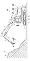
- FIG. 1 is a side view of a shovel according to an embodiment of the present disclosure
- FIG. 2 is a block diagram showing a configuration example of a drive system of the excavator of FIG. 1;
- FIG. FIG. 2 is a schematic diagram showing a configuration example of a hydraulic system mounted on the excavator of FIG. 1;
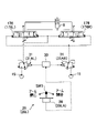
- FIG. 4 is a diagram of part of the hydraulic system for operating the arm cylinder;
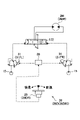
- FIG. 4 is a diagram of a portion of the hydraulic system for operating the boom cylinder;
- FIG. 4 is a diagram of a portion of the hydraulic system for operating the bucket cylinder;
- FIG. 4 is a diagram of a portion of the hydraulic system for operating the swing hydraulic motor;
- FIG. 4 is a diagram of a portion of the hydraulic system for operation of the left travel hydraulic motor;
- FIG. 4 is a diagram of a portion of the hydraulic system for operation of the right travel hydraulic motor;
- 2 is a block diagram showing another configuration example of the drive system of the excavator of FIG. 1;
- FIG. 10 is a flowchart of facing processing;
- FIG. 10 is a top view of the excavator when the facing process is performed;
- FIG. 10 is a top view of the excavator when the facing process is performed;
- FIG. 10 is a perspective view of the excavator when the facing process is performed;
- FIG. 10 is a perspective view of the excavator when the facing process is performed;
- FIG. 10 is a perspective view of the excavator when the facing process is performed;
- FIG. 10 is a perspective view of the excavator when the facing process is performed;
- FIG. 10 is a perspective view of the excavator when the facing process is performed;
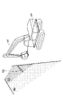
- FIG. 12 is a perspective view of the target construction surface when the facing target surface selection process is executed;
- FIG. 12 is a perspective view of the target construction surface when the facing target surface selection process is executed;
- FIG. 12 is a perspective view of the target construction surface when the facing target surface selection process is executed;
- FIG. 1 is a side view of a shovel 100 as an excavator according to an embodiment of the present disclosure.
- An upper revolving body 3 is rotatably mounted on a lower traveling body 1 of the excavator 100 via a revolving mechanism 2 .
- a boom 4 is attached to the upper revolving body 3 .
- An arm 5 is attached to the tip of the boom 4, and a bucket 6 is attached to the tip of the arm 5 as an end attachment.
- Bucket 6 may be a slope bucket.
- the boom 4, arm 5, and bucket 6 constitute an excavation attachment as an example of an attachment.
- the boom 4 is driven by a boom cylinder 7
- the arm 5 is driven by an arm cylinder 8
- the bucket 6 is driven by a bucket cylinder 9 .
- a boom angle sensor S1 is attached to the boom 4
- an arm angle sensor S2 is attached to the arm 5
- a bucket angle sensor S3 is attached to the bucket 6.
- the boom angle sensor S1 is configured to detect the rotation angle of the boom 4.
- the boom angle sensor S1 is an acceleration sensor, and can detect the rotation angle of the boom 4 with respect to the upper rotating body 3 (hereinafter referred to as "boom angle").
- the boom angle is, for example, the minimum angle when the boom 4 is lowered, and increases as the boom 4 is raised.
- the arm angle sensor S2 is configured to detect the rotation angle of the arm 5.
- the arm angle sensor S2 is an acceleration sensor, and can detect the rotation angle of the arm 5 with respect to the boom 4 (hereinafter referred to as "arm angle").
- the arm angle is, for example, the minimum angle when the arm 5 is closed most, and increases as the arm 5 is opened.
- the bucket angle sensor S3 is configured to detect the rotation angle of the bucket 6.
- the bucket angle sensor S3 is an acceleration sensor, and can detect the rotation angle of the bucket 6 with respect to the arm 5 (hereinafter referred to as "bucket angle").
- the bucket angle is, for example, the smallest angle when the bucket 6 is closed most, and increases as the bucket 6 opens.
- the boom angle sensor S1, the arm angle sensor S2, and the bucket angle sensor S3 are each a potentiometer using a variable resistor, a stroke sensor that detects the stroke amount of the corresponding hydraulic cylinder, and a rotation angle around the connecting pin.
- a rotary encoder, a gyro sensor, or a combination of an acceleration sensor and a gyro sensor may be used.
- the upper rotating body 3 includes a controller 30, an audio output device 43, a display device 45, an input device 46, a storage device 47, a body tilt sensor S4, a turning angular velocity sensor S5, a camera S6, a communication device T1, a positioning device P1, and the like. is installed.
- the controller 30 is configured to function as a main control unit that controls the driving of the excavator 100 .
- the controller 30 is configured by a computer including a CPU, RAM, ROM, and the like.
- Various functions of the controller 30 are implemented by the CPU executing programs stored in the ROM, for example.
- the various functions include, for example, a machine guidance function that guides the manual operation of the excavator 100 by the operator, and a machine control function that automatically supports the manual operation of the excavator 100 by the operator.
- a machine controller 50 included in controller 30 is configured to perform machine guidance and machine control functions.
- the display device 45 is configured to display various information.
- the display device 45 may be connected to the controller 30 via a communication network such as CAN, or may be connected to the controller 30 via a dedicated line.
- the input device 46 is configured so that the operator can input various information to the controller 30 .
- the input device 46 includes a touch panel, a knob switch, a membrane switch, and the like installed inside the cabin 10 .
- the audio output device 43 is configured to output audio.
- the audio output device 43 may be, for example, an in-vehicle speaker connected to the controller 30 or an alarm device such as a buzzer.
- the audio output device 43 is configured to output various information as audio in response to an audio output command from the controller 30 .
- the storage device 47 is configured to store various information.
- the storage device 47 is, for example, a non-volatile storage medium such as a semiconductor memory.
- the storage device 47 may store information output by various devices during operation of the excavator 100, or may store information acquired via various devices before the excavator 100 starts operating.
- the storage device 47 may store, for example, information on the target construction surface (design surface) acquired via the communication device T1 or the like.
- the target construction surface may be set by the operator of the excavator 100, or may be set by the construction manager or the like.
- the fuselage tilt sensor S4 is configured to detect the tilt of the upper revolving structure 3 with respect to the virtual horizontal plane.
- the fuselage tilt sensor S4 is an acceleration sensor that detects the tilt angle of the upper revolving structure 3 about the front-rear axis and the tilt angle about the left-right axis.
- the longitudinal axis and the lateral axis of the upper revolving body 3 are orthogonal to each other, for example, at a shovel center point, which is one point on the revolving axis of the excavator 100 .
- the turning angular velocity sensor S5 is configured to detect the turning angular velocity of the upper turning body 3.
- the turning angular velocity sensor S5 may be configured to detect or calculate the turning angle of the upper turning body 3 .
- the turning angular velocity sensor S5 is a gyro sensor.
- the turning angular velocity sensor S5 may be a resolver, a rotary encoder, or the like.
- the camera S6 is an example of a space recognition device, and is configured to acquire an image around the shovel 100.
- the cameras S6 include a front camera S6F that captures the space in front of the excavator 100, a left camera S6L that captures the space to the left of the excavator 100, a right camera S6R that captures the space to the right of the excavator 100, and a rear camera S6B that captures an image of the space behind the excavator 100 .
- the camera S6 is, for example, a monocular camera having an imaging device such as a CCD or CMOS, and outputs the captured image to the display device 45.
- the camera S6 may be a stereo camera, a distance image camera, or the like.
- the camera S6 may be replaced with another space recognition device such as an ultrasonic sensor, a millimeter wave radar, a LIDAR, or an infrared sensor, or may be replaced with a combination of another space recognition device and a camera.
- the front camera S6F is attached to the ceiling of the cabin 10, that is, inside the cabin 10, for example.
- the front camera S ⁇ b>6 ⁇ /b>F may be attached to the roof of the cabin 10 , that is, to the outside of the cabin 10 .
- the left camera S6L is attached to the left end of the upper surface of the upper rotating body 3
- the right camera S6R is attached to the right end of the upper surface of the upper rotating body 3
- the rear camera S6B is attached to the rear end of the upper surface of the upper rotating body 3. .
- the communication device T1 controls communication with external equipment outside the shovel 100.
- the communication device T1 controls communication with external devices via a satellite communication network, a mobile phone communication network, an Internet network, or the like.
- the external device may be, for example, a management device such as a server installed in an external facility, or may be a support device such as a smart phone carried by a worker around the excavator 100 .
- the external device is configured, for example, to manage construction information related to one or more excavators 100 .
- the construction information includes, for example, information related to at least one of the operation time, fuel consumption, work amount, and the like of the excavator 100 .
- the amount of work is, for example, the amount of excavated earth and sand, the amount of earth and sand loaded on the platform of the dump truck, and the like.
- the excavator 100 is configured to transmit construction information related to the excavator 100 to an external device at predetermined time intervals via the communication device T1.
- the positioning device P1 is configured to measure the position of the upper revolving structure 3.
- the positioning device P1 may be configured to measure the orientation of the upper swing structure 3 .
- the positioning device P ⁇ b>1 is, for example, a GNSS compass, detects the position and orientation of the upper swing structure 3 , and outputs the detected values to the controller 30 . Therefore, the positioning device P1 can function as an orientation detection device that detects the orientation of the upper revolving structure 3 .
- the orientation detection device may be an orientation sensor attached to the upper swing structure 3 .
- FIG. 2 is a block diagram showing a configuration example of the drive system of the excavator 100, in which the mechanical power system, hydraulic oil line, pilot line, and electric control system are indicated by double lines, solid lines, broken lines, and dotted lines, respectively.
- a drive system of the excavator 100 mainly includes an engine 11, a regulator 13, a main pump 14, a pilot pump 15, a control valve unit 17, an operation device 26, a discharge pressure sensor 28, an operation sensor 29, a controller 30, a proportional valve 31, and the like. including.
- the engine 11 is a drive source for the shovel 100.
- the engine 11 is, for example, a diesel engine that operates to maintain a predetermined number of revolutions.
- the output shaft of the engine 11 is connected to the input shafts of the main pump 14 and the pilot pump 15 .
- the main pump 14 is configured to supply hydraulic oil to the control valve unit 17 via a hydraulic oil line.
- the main pump 14 is a swash plate type variable displacement hydraulic pump.
- the regulator 13 is configured to control the discharge amount of the main pump 14 .
- the regulator 13 controls the discharge amount of the main pump 14 by adjusting the tilt angle of the swash plate of the main pump 14 according to the control command from the controller 30 .
- the controller 30 receives the output of the operation sensor 29 or the like, outputs a control command to the regulator 13 as necessary, and changes the discharge amount of the main pump 14 .
- the pilot pump 15 supplies hydraulic fluid to various hydraulic control devices including the proportional valve 31 through the pilot line.
- the pilot pump 15 is a fixed displacement hydraulic pump.
- the pilot pump 15 may be omitted.
- the function previously performed by the pilot pump 15 may be realized by the main pump 14 . That is, the main pump 14 is provided with a circuit separate from the function of supplying the hydraulic oil to the control valve unit 17, and supplies the hydraulic oil to the proportional valve 31 and the like after reducing the supply pressure of the hydraulic oil by means of a throttle or the like. It may have functions.
- the control valve unit 17 is a hydraulic control device that controls the hydraulic system in the excavator 100.
- the control valve unit 17 includes control valves 171-176.
- the control valve unit 17 can selectively supply hydraulic fluid discharged from the main pump 14 to one or more hydraulic actuators through the control valves 171-176.
- the control valves 171 to 176 are configured to control the flow rate of hydraulic fluid flowing from the main pump 14 to the hydraulic actuators and the flow rate of hydraulic fluid flowing from the hydraulic actuators to the hydraulic fluid tank.
- Hydraulic actuators include a boom cylinder 7, an arm cylinder 8, a bucket cylinder 9, a travel hydraulic motor 2M, and a swing hydraulic motor 2A.
- the traveling hydraulic motor 2M includes a left traveling hydraulic motor 2ML and a right traveling hydraulic motor 2MR.
- the swing hydraulic motor 2A may be a swing motor generator as an electric actuator.
- the operating device 26 is a device used by the operator to operate the actuator.
- the actuator includes at least one of a hydraulic actuator and an electric actuator.
- the discharge pressure sensor 28 is configured to detect the discharge pressure of the main pump 14 .
- the discharge pressure sensor 28 outputs the detected value to the controller 30 .
- the operation sensor 29 is configured to detect the content of the operator's operation using the operation device 26 .
- the operation sensor 29 detects the operation direction and the amount of operation of the operation device 26 corresponding to each actuator, and outputs the detected values to the controller 30 .
- the controller 30 controls the opening area of the proportional valve 31 according to the output of the operation sensor 29 .
- the controller 30 then supplies the hydraulic oil discharged by the pilot pump 15 to the pilot port of the corresponding control valve in the control valve unit 17 .
- the pressure (pilot pressure) of hydraulic fluid supplied to each of the pilot ports is, in principle, a pressure corresponding to the operation direction and amount of operation of the operation device 26 corresponding to each hydraulic actuator.
- the operation device 26 is configured to supply the hydraulic oil discharged by the pilot pump 15 to the pilot port of the corresponding control valve in the control valve unit 17 .
- a proportional valve 31 functioning as a control valve for machine control is arranged in a conduit connecting the pilot pump 15 and a pilot port of a control valve in the control valve unit 17 so that the flow area of the conduit can be changed. It is configured.
- the proportional valve 31 operates according to a control command output by the controller 30 . Therefore, the controller 30 can supply the hydraulic oil discharged by the pilot pump 15 to the pilot port of the control valve in the control valve unit 17 via the proportional valve 31 regardless of the operation of the operating device 26 by the operator.
- the controller 30 can operate the hydraulic actuator corresponding to the specific operating device 26 even when the specific operating device 26 is not operated.
- Machine controller 50 is configured, for example, to perform machine guidance functions.
- the machine control device 50 provides the operator with work information such as the distance between the target work surface and the work site of the attachment.
- Information about the target construction surface is stored in advance in the storage device 47, for example.
- the machine control device 50 may acquire information about the target construction surface from an external device via the communication device T1.
- Information about the target construction surface is expressed, for example, in a reference coordinate system.
- the reference coordinate system is, for example, the world geodetic system.
- the world geodetic system is a three-dimensional orthogonal XYZ system with the origin at the center of gravity of the earth, the X axis in the direction of the intersection of the Greenwich meridian and the equator, the Y axis in the direction of 90 degrees east longitude, and the Z axis in the direction of the North Pole. coordinate system.
- the target construction plane may be set based on a relative positional relationship with the reference point. In this case, the operator may set any point on the construction site as the reference point.
- the working part of the attachment is, for example, the tip (toe) of the bucket 6 or the rear surface of the bucket 6 or the like.
- the machine control device 50 may be configured to guide the operation of the excavator 100 by transmitting work information to the operator via the display device 45, the audio output device 43, or the like.
- the machine control device 50 may perform a machine control function that automatically assists the manual operation of the excavator 100 by the operator.
- the machine control device 50 controls at least one of the boom 4, the arm 5, and the bucket 6 so that the tip position of the bucket 6 coincides with the target construction surface when the operator is manually excavating. can be run automatically.
- the machine control device 50 is incorporated in the controller 30 in this embodiment, it may be a control device provided separately from the controller 30 .
- the machine control device 50 is composed of, for example, a computer including a CPU and internal memory, like the controller 30 .
- Various functions of the machine control device 50 are implemented by the CPU executing programs stored in the internal memory.
- the machine control device 50 and the controller 30 are communicably connected to each other through a communication network such as CAN.
- the machine control device 50 may be mounted in a management device such as a server installed in an external facility, or may be mounted in a support device such as a smart phone carried by a worker around the excavator 100. good.
- FIG. 3 is a diagram showing a configuration example of a hydraulic system mounted on the excavator 100.
- FIG. 3 shows the mechanical driveline, hydraulic lines, pilot lines and electrical control system in double, solid, dashed and dotted lines respectively.
- a hydraulic system of the excavator 100 mainly includes an engine 11, a regulator 13, a main pump 14, a pilot pump 15, a control valve unit 17, an operation device 26, a discharge pressure sensor 28, an operation sensor 29, a controller 30, and the like.
- the hydraulic system is configured so that hydraulic oil can be circulated from the main pump 14 driven by the engine 11 to the hydraulic oil tank through the center bypass line 40 or parallel line 42.
- the engine 11 is a drive source for the shovel 100.
- the engine 11 is, for example, a diesel engine that operates to maintain a predetermined number of revolutions.
- An output shaft of the engine 11 is connected to respective input shafts of the main pump 14 and the pilot pump 15 .
- the main pump 14 is configured to supply hydraulic oil to the control valve unit 17 via a hydraulic oil line.
- the main pump 14 is a swash plate type variable displacement hydraulic pump.
- the regulator 13 is configured to be able to control the discharge amount of the main pump 14 .
- the regulator 13 controls the discharge amount of the main pump 14 by adjusting the tilt angle of the swash plate of the main pump 14 according to the control command from the controller 30 .
- the pilot pump 15 is an example of a pilot pressure generating device, and is configured to supply hydraulic fluid to hydraulic control equipment via a pilot line.
- the pilot pump 15 is a fixed displacement hydraulic pump.
- the pilot pressure generator may be implemented by the main pump 14 . That is, the main pump 14 may have a function of supplying hydraulic fluid to various hydraulic control devices via a pilot line in addition to the function of supplying hydraulic fluid to the control valve unit 17 via the hydraulic fluid line. In this case, pilot pump 15 may be omitted.
- the control valve unit 17 is a hydraulic control device that controls the hydraulic system in the excavator 100.
- the control valve unit 17 includes control valves 171-176.
- Control valve 175 includes control valve 175L and control valve 175R
- control valve 176 includes control valve 176L and control valve 176R.
- the control valve unit 17 is configured to selectively supply hydraulic fluid discharged from the main pump 14 to one or more hydraulic actuators through control valves 171-176.
- the control valves 171 to 176 for example, control the flow rate of hydraulic fluid flowing from the main pump 14 to the hydraulic actuator and the flow rate of hydraulic fluid flowing from the hydraulic actuator to the hydraulic fluid tank.
- Hydraulic actuators include a boom cylinder 7, an arm cylinder 8, a bucket cylinder 9, a travel hydraulic motor 2M, and a swing hydraulic motor 2A.
- the traveling hydraulic motor 2M includes a left traveling hydraulic motor 2ML and a right traveling hydraulic motor 2MR.
- the operating device 26 is configured so that the operator can operate the actuator.
- the operating device 26 includes a hydraulic actuator operating device configured to allow an operator to operate the hydraulic actuator.
- the hydraulic actuator operation device is configured to supply the hydraulic oil discharged by the pilot pump 15 to the pilot port of the corresponding control valve in the control valve unit 17 via the pilot line.
- the pressure (pilot pressure) of hydraulic fluid supplied to each of the pilot ports is a pressure corresponding to the operation direction and amount of operation of the operating device 26 corresponding to each of the hydraulic actuators.
- the discharge pressure sensor 28 is configured to detect the discharge pressure of the main pump 14 .
- the discharge pressure sensor 28 outputs the detected value to the controller 30 .
- the operation sensor 29 is configured to detect the content of the operation of the operation device 26 by the operator.
- the operation sensor 29 detects the operation direction and the amount of operation of the operation device 26 corresponding to each actuator, and outputs the detected values to the controller 30 .
- the main pump 14 includes a left main pump 14L and a right main pump 14R.
- the left main pump 14L circulates the hydraulic oil to the hydraulic oil tank through the left center bypass pipe 40L or the left parallel pipe 42L
- the right main pump 14R circulates the right center bypass pipe 40R or the right parallel pipe 42R. to circulate hydraulic oil to the hydraulic oil tank.
- the left center bypass line 40L is a hydraulic oil line passing through the control valves 171, 173, 175L and 176L arranged inside the control valve unit 17.
- the right center bypass line 40R is a hydraulic oil line passing through control valves 172, 174, 175R and 176R arranged in the control valve unit 17.
- the control valve 171 controls the flow of hydraulic fluid in order to supply the hydraulic fluid discharged by the left main pump 14L to the left traveling hydraulic motor 2ML and to discharge the hydraulic fluid discharged by the left traveling hydraulic motor 2ML to the hydraulic fluid tank. It is a switching spool valve.
- the control valve 172 controls the flow of hydraulic fluid in order to supply the hydraulic fluid discharged by the right main pump 14R to the right traveling hydraulic motor 2MR and to discharge the hydraulic fluid discharged by the right traveling hydraulic motor 2MR to the hydraulic fluid tank. It is a switching spool valve.
- the control valve 173 supplies the hydraulic oil discharged by the left main pump 14L to the swing hydraulic motor 2A and discharges the hydraulic oil discharged by the swing hydraulic motor 2A to the hydraulic oil tank. valve.
- the control valve 174 is a spool valve that switches the flow of hydraulic oil to supply the hydraulic oil discharged by the right main pump 14R to the bucket cylinder 9 and to discharge the hydraulic oil in the bucket cylinder 9 to the hydraulic oil tank. .
- the control valve 175L is a spool valve that switches the flow of hydraulic oil in order to supply the hydraulic oil discharged by the left main pump 14L to the boom cylinder 7.
- the control valve 175R is a spool valve that switches the flow of hydraulic oil to supply the hydraulic oil discharged from the right main pump 14R to the boom cylinder 7 and to discharge the hydraulic oil in the boom cylinder 7 to the hydraulic oil tank. .
- the control valve 176L is a spool valve that switches the flow of hydraulic fluid to supply the hydraulic fluid discharged by the left main pump 14L to the arm cylinder 8 and to discharge the hydraulic fluid in the arm cylinder 8 to the hydraulic fluid tank. .
- the control valve 176R is a spool valve that switches the flow of hydraulic fluid to supply the hydraulic fluid discharged from the right main pump 14R to the arm cylinder 8 and to discharge the hydraulic fluid in the arm cylinder 8 to the hydraulic fluid tank. .
- the left parallel pipeline 42L is a hydraulic oil line parallel to the left center bypass pipeline 40L.
- the left parallel pipeline 42L supplies hydraulic fluid to the downstream control valves when the flow of hydraulic fluid through the left center bypass pipeline 40L is restricted or blocked by any of the control valves 171, 173, and 175L.
- the right parallel pipeline 42R is a hydraulic oil line parallel to the right center bypass pipeline 40R.
- the right parallel line 42R supplies hydraulic fluid to more downstream control valves when the flow of hydraulic fluid through the right center bypass line 40R is restricted or blocked by any of the control valves 172, 174, and 175R. can.
- the regulator 13 includes a left regulator 13L and a right regulator 13R.
- the left regulator 13L controls the discharge amount of the left main pump 14L by adjusting the tilt angle of the swash plate of the left main pump 14L according to the discharge pressure of the left main pump 14L.
- the left regulator 13L adjusts the tilt angle of the swash plate of the left main pump 14L according to an increase in the discharge pressure of the left main pump 14L, for example, to reduce the discharge amount.
- the operating device 26 includes a left operating lever 26L, a right operating lever 26R and a travel lever 26D.
- the travel lever 26D includes a left travel lever 26DL and a right travel lever 26DR.
- the left operating lever 26L is used for turning operation and operating the arm 5.
- the hydraulic oil discharged by the pilot pump 15 is used to introduce a control pressure corresponding to the amount of lever operation to the pilot port of the control valve 176 .
- hydraulic oil discharged from the pilot pump 15 is used to introduce a control pressure corresponding to the amount of lever operation to the pilot port of the control valve 173 .
- the left operation lever 26L when the left operation lever 26L is operated in the arm closing direction, it introduces hydraulic fluid into the right pilot port of the control valve 176L and introduces hydraulic fluid into the left pilot port of the control valve 176R. . Further, when the left operating lever 26L is operated in the arm opening direction, it introduces hydraulic fluid into the left pilot port of the control valve 176L and introduces hydraulic fluid into the right pilot port of the control valve 176R.
- hydraulic oil is introduced into the left pilot port of the control valve 173, and when it is operated in the right turning direction, the right pilot port of the control valve 173 is introduced. Hydraulic oil is introduced into
- the right operating lever 26R is used to operate the boom 4 and the bucket 6.
- the hydraulic oil discharged by the pilot pump 15 is used to introduce a control pressure corresponding to the amount of lever operation to the pilot port of the control valve 175 .
- hydraulic oil discharged from the pilot pump 15 is used to introduce a control pressure corresponding to the amount of lever operation to the pilot port of the control valve 174 .
- hydraulic fluid is introduced into the left pilot port of the control valve 175R.
- hydraulic fluid is introduced into the right pilot port of the control valve 175L and introduces hydraulic fluid into the left pilot port of the control valve 175R.
- hydraulic oil is introduced into the right pilot port of the control valve 174, and when it is operated in the bucket opening direction, the hydraulic oil is introduced into the left pilot port of the control valve 174. Introduce hydraulic oil.
- the left operating lever 26L that is operated in the left-right direction may be referred to as a "rotation operating lever”, and the left operating lever 26L that is operated in the front-rear direction may be referred to as an "arm operating lever”.
- the right operating lever 26R that is operated in the left-right direction is sometimes referred to as a “bucket operating lever”, and the right operating lever 26R that is operated in the front-rear direction is sometimes referred to as a "boom operating lever”.
- the travel lever 26D is used to operate the crawler 1C.
- the left travel lever 26DL is used to operate the left crawler 1CL. It may be configured to be interlocked with the left travel pedal.
- the hydraulic oil discharged by the pilot pump 15 is used to introduce a control pressure corresponding to the amount of lever operation to the pilot port of the control valve 171 .
- the right travel lever 26DR is used to operate the right crawler 1CR. It may be configured to interlock with the right travel pedal.
- the hydraulic oil discharged by the pilot pump 15 is used to introduce a control pressure corresponding to the amount of lever operation to the pilot port of the control valve 172 .
- the discharge pressure sensor 28 includes a discharge pressure sensor 28L and a discharge pressure sensor 28R.
- the discharge pressure sensor 28L detects the discharge pressure of the left main pump 14L and outputs the detected value to the controller 30 . The same applies to the discharge pressure sensor 28R.
- the operation sensor 29 includes operation sensors 29LA, 29LB, 29RA, 29RB, 29DL, and 29DR.
- the operation sensor 29LA detects the content of the operator's operation of the left operation lever 26L in the front-rear direction, and outputs the detected value to the controller 30.
- FIG. The details of the operation are, for example, the lever operation direction, lever operation amount (lever operation angle), and the like.
- the operation sensor 29LB detects the content of the operator's operation of the left operation lever 26L in the horizontal direction, and outputs the detected value to the controller 30.
- the operation sensor 29RA detects the content of the operator's operation of the right operation lever 26R in the front-rear direction, and outputs the detected value to the controller 30.
- the operation sensor 29 RB detects the content of the operator's operation of the right operation lever 26 R in the horizontal direction, and outputs the detected value to the controller 30 .
- the operation sensor 29DL detects the content of the operator's operation of the left travel lever 26DL in the front-rear direction, and outputs the detected value to the controller 30 .
- the operation sensor 29DR detects the content of the operator's operation of the right traveling lever 26DR in the front-rear direction, and outputs the detected value to the controller 30 .
- the controller 30 receives the output of the operation sensor 29, outputs a control command to the regulator 13 as necessary, and changes the discharge amount of the main pump 14.
- the controller 30 also receives the output of a control pressure sensor 19 provided upstream of the throttle 18 and outputs a control command to the regulator 13 as necessary to change the discharge amount of the main pump 14 .
- the throttle 18 includes a left throttle 18L and a right throttle 18R
- the control pressure sensor 19 includes a left control pressure sensor 19L and a right control pressure sensor 19R.
- a left throttle 18L is arranged between the most downstream control valve 176L and the hydraulic oil tank in the left center bypass pipe 40L. Therefore, the flow of hydraulic oil discharged from the left main pump 14L is restricted by the left throttle 18L.
- the left throttle 18L generates a control pressure for controlling the left regulator 13L.
- the left control pressure sensor 19L is a sensor for detecting this control pressure, and outputs the detected value to the controller 30.
- the controller 30 controls the discharge amount of the left main pump 14L by adjusting the tilt angle of the swash plate of the left main pump 14L according to this control pressure.
- the controller 30 decreases the discharge amount of the left main pump 14L as the control pressure increases, and increases the discharge amount of the left main pump 14L as the control pressure decreases.
- the discharge amount of the right main pump 14R is similarly controlled.
- the controller 30 increases the discharge amount of the left main pump 14L, circulates a sufficient amount of hydraulic oil to the hydraulic actuator to be operated, and ensures the driving of the hydraulic actuator to be operated. Note that the controller 30 similarly controls the discharge amount of the right main pump 14R.
- the hydraulic system of FIG. 3 can suppress wasteful energy consumption in the main pump 14 in the standby state. Wasteful energy consumption includes pumping loss caused by the hydraulic fluid discharged by the main pump 14 in the center bypass pipe 40 . Further, the hydraulic system of FIG. 3 can reliably supply necessary and sufficient working oil from the main pump 14 to the hydraulic actuator to be operated when the hydraulic actuator is to be operated.
- FIGS. 4A-4D, 5A and 5B are partial cutaway views of the hydraulic system.
- FIG. 4A is a view of the hydraulic system portion related to the operation of the arm cylinder 8
- FIG. 4B is a view of the hydraulic system portion related to the operation of the boom cylinder 7.
- FIG. 4C is a diagram extracting a hydraulic system portion relating to the operation of the bucket cylinder 9
- FIG. 4D is a diagram extracting a hydraulic system portion relating to the operation of the turning hydraulic motor 2A.
- FIG. 5A is a diagram extracting a hydraulic system portion related to the operation of the left travel hydraulic motor 2ML
- FIG. 5B is a diagram extracting a hydraulic system portion related to the operation of the right travel hydraulic motor 2MR.
- the hydraulic system includes a proportional valve 31, as shown in FIGS. 4A-4D, 5A, and 5B.
- the proportional valve 31 includes proportional valves 31AL-31DL and 31AR-31DR.
- the proportional valve 31 functions as a control valve for machine control.
- the proportional valve 31 is arranged in a pipeline connecting the pilot pump 15 and the pilot port of the corresponding control valve in the control valve unit 17, and is configured to change the flow area of the pipeline.
- the proportional valve 31 operates according to a control command output by the controller 30 . Therefore, the controller 30 supplies the hydraulic oil discharged by the pilot pump 15 to the pilot port of the corresponding control valve in the control valve unit 17 via the proportional valve 31, regardless of the operation of the operating device 26 by the operator. can.
- the controller 30 can then cause the pilot pressure generated by the proportional valve 31 to act on the pilot port of the corresponding control valve.
- the controller 30 can operate the hydraulic actuator corresponding to the specific operating device 26 even when the specific operating device 26 is not operated. Further, even when a specific operating device 26 is being operated, the controller 30 can forcibly stop the operation of the hydraulic actuator corresponding to the specific operating device 26 .
- the left operating lever 26L is used to operate the arm 5, as shown in FIG. 4A.
- the left operation lever 26L utilizes hydraulic oil discharged by the pilot pump 15 to apply a pilot pressure to the pilot port of the control valve 176 according to the operation in the front-rear direction. More specifically, when the left operation lever 26L is operated in the arm closing direction (backward), the pilot pressure corresponding to the amount of operation is applied to the right pilot port of the control valve 176L and the left pilot port of the control valve 176R. act. Further, when the left operating lever 26L is operated in the arm opening direction (forward direction), a pilot pressure corresponding to the amount of operation is applied to the left pilot port of the control valve 176L and the right pilot port of the control valve 176R.
- the operating device 26 is provided with a switch SW.
- the switch SW includes a switch SW1 and a switch SW2.
- the switch SW1 is a push button switch provided at the tip of the left operating lever 26L. The operator can operate the left operating lever 26L while pressing the switch SW1.
- the switch SW1 may be provided on the right operating lever 26R, or may be provided at another position inside the cabin 10.
- the switch SW2 is a push button switch provided at the tip of the left travel lever 26DL. The operator can operate the left travel lever 26DL while pressing the switch SW2.
- Switch SW2 may be provided on right travel lever 26DR or may be provided at another position within cabin 10 .
- the operation sensor 29LA detects the content of the operator's operation of the left operation lever 26L in the front-rear direction, and outputs the detected value to the controller 30.
- the proportional valve 31AL operates according to a control command (current command) output by the controller 30. Then, it adjusts the pilot pressure by hydraulic oil introduced from the pilot pump 15 through the proportional valve 31AL to the right pilot port of the control valve 176L and the left pilot port of the control valve 176R.
- the proportional valve 31AR operates according to a control command (current command) output by the controller 30. Then, it adjusts the pilot pressure of hydraulic oil introduced from the pilot pump 15 through the proportional valve 31AR into the left pilot port of the control valve 176L and the right pilot port of the control valve 176R.
- the proportional valve 31AL can adjust the pilot pressure so that the control valve 176L and the control valve 176R can be stopped at any valve position.
- the proportional valve 31AR can adjust the pilot pressure so that the control valve 176L and the control valve 176R can be stopped at any valve position.
- the controller 30 supplies hydraulic oil discharged from the pilot pump 15 to the right pilot port of the control valve 176L and the left pilot port of the control valve 176R via the proportional valve 31AL in response to the arm closing operation by the operator. can.
- the controller 30 supplies hydraulic oil discharged from the pilot pump 15 to the right pilot port of the control valve 176L and the left pilot port of the control valve 176R via the proportional valve 31AL, regardless of the arm closing operation by the operator. can. That is, the controller 30 can close the arm 5 according to the arm closing operation by the operator or regardless of the arm closing operation by the operator.
- the controller 30 can supply hydraulic fluid discharged from the pilot pump 15 to the left pilot port of the control valve 176L and the right pilot port of the control valve 176R via the proportional valve 31AR in response to the arm opening operation by the operator.
- the controller 30 supplies hydraulic oil discharged from the pilot pump 15 to the left pilot port of the control valve 176L and the right pilot port of the control valve 176R via the proportional valve 31AR, regardless of the arm opening operation by the operator. can. That is, the controller 30 can open the arm 5 according to the arm opening operation by the operator or regardless of the arm opening operation by the operator.
- the controller 30 can operate the closing side pilot port of the control valve 176 (the left side pilot port of the control valve 176L and the By reducing the pilot pressure acting on the right pilot port of the control valve 176R, the closing operation of the arm 5 can be forcibly stopped. The same applies to the case where the opening operation of the arm 5 is forcibly stopped while the operator is performing the arm opening operation.
- the controller 30 may optionally control the proportional valve 31AR to control the valve 31AR on the opposite side of the closed side pilot port of the control valve 176, even when the operator is performing an arm closing operation.
- the controller 30 may optionally control the proportional valve 31AR to control the valve 31AR on the opposite side of the closed side pilot port of the control valve 176, even when the operator is performing an arm closing operation.
- the arm 5 may be forcibly stopped. The same applies to the case of forcibly stopping the opening operation of the arm 5 when the arm opening operation is performed by the operator.
- the operation of the boom 4 is forced when the operator is performing a boom-up operation or a boom-down operation.
- the bucket 6 is forcibly stopped when the bucket closing operation or bucket opening operation is performed by the operator, when the operation of the bucket 6 is forced to stop, and when the turning operation is performed by the operator.
- the revolving motion of the revolving body 3 is forcibly stopped.
- the running motion of the lower running body 1 is forcibly stopped while the running operation is being performed by the operator.
- the right operating lever 26R is used to operate the boom 4. Specifically, the right operating lever 26R utilizes the hydraulic oil discharged by the pilot pump 15 to apply a pilot pressure to the pilot port of the control valve 175 according to the operation in the front-rear direction. More specifically, when the right operation lever 26R is operated in the boom raising direction (backward), the pilot pressure corresponding to the amount of operation is applied to the right pilot port of the control valve 175L and the left pilot port of the control valve 175R. act. Further, when the right operation lever 26R is operated in the boom lowering direction (forward direction), a pilot pressure corresponding to the amount of operation is applied to the right pilot port of the control valve 175R.
- the operation sensor 29RA detects the content of the operator's operation of the right operation lever 26R in the front-rear direction, and outputs the detected value to the controller 30.
- the proportional valve 31BL operates according to a control command (current command) output by the controller 30. Then, it adjusts the pilot pressure by the hydraulic oil introduced from the pilot pump 15 through the proportional valve 31BL to the right pilot port of the control valve 175L and the left pilot port of the control valve 175R.
- the proportional valve 31BR operates according to a control command (current command) output by the controller 30 . Then, it adjusts the pilot pressure by hydraulic oil introduced from the pilot pump 15 to the right pilot port of the control valve 175R via the proportional valve 31BR.
- the proportional valve 31BL can adjust the pilot pressure so that the control valve 175L and the control valve 175R can be stopped at any valve position. Also, the proportional valve 31BR can adjust the pilot pressure so that the control valve 175R can be stopped at any valve position.
- the controller 30 supplies hydraulic oil discharged from the pilot pump 15 to the right pilot port of the control valve 175L and the left pilot port of the control valve 175R via the proportional valve 31BL in response to the operator's boom raising operation. can.
- the controller 30 supplies hydraulic oil discharged from the pilot pump 15 to the right pilot port of the control valve 175L and the left pilot port of the control valve 175R via the proportional valve 31BL, regardless of the operator's operation to raise the boom. can. That is, the controller 30 can raise the boom 4 according to the operator's boom raising operation or regardless of the operator's boom raising operation.
- the controller 30 can supply the hydraulic oil discharged by the pilot pump 15 to the right pilot port of the control valve 175R via the proportional valve 31BR in response to the boom lowering operation by the operator.
- the controller 30 can supply the hydraulic oil discharged from the pilot pump 15 to the right pilot port of the control valve 175R via the proportional valve 31BR regardless of the boom lowering operation by the operator. That is, the controller 30 can lower the boom 4 according to the operator's boom lowering operation or regardless of the operator's boom lowering operation.
- the right operating lever 26R is also used to operate the bucket 6, as shown in FIG. 4C. Specifically, the right operating lever 26R utilizes the hydraulic oil discharged by the pilot pump 15 to apply a pilot pressure to the pilot port of the control valve 174 according to the operation in the left-right direction. More specifically, the right operating lever 26R applies a pilot pressure corresponding to the amount of operation to the left pilot port of the control valve 174 when operated in the bucket closing direction (leftward direction). Further, when the right operation lever 26R is operated in the bucket opening direction (rightward), a pilot pressure corresponding to the amount of operation is applied to the right pilot port of the control valve 174. As shown in FIG.
- the operation sensor 29RB detects the content of the operator's operation of the right operation lever 26R in the left-right direction, and outputs the detected value to the controller 30.
- the proportional valve 31CL operates according to a control command (current command) output by the controller 30. Then, it adjusts the pilot pressure by hydraulic oil introduced from the pilot pump 15 to the left pilot port of the control valve 174 via the proportional valve 31CL.
- the proportional valve 31CR operates according to a control command (current command) output by the controller 30 . Then, it adjusts the pilot pressure by hydraulic oil introduced from the pilot pump 15 to the right pilot port of the control valve 174 via the proportional valve 31CR.
- the proportional valve 31CL can adjust the pilot pressure so that the control valve 174 can be stopped at any valve position.
- the proportional valve 31CR can adjust the pilot pressure so that the control valve 174 can be stopped at any valve position.
- the controller 30 can supply the hydraulic oil discharged by the pilot pump 15 to the left pilot port of the control valve 174 via the proportional valve 31CL in response to the bucket closing operation by the operator. Further, the controller 30 can supply the hydraulic oil discharged from the pilot pump 15 to the left pilot port of the control valve 174 via the proportional valve 31CL regardless of the bucket closing operation by the operator. That is, the controller 30 can close the bucket 6 according to the bucket closing operation by the operator or regardless of the bucket closing operation by the operator.
- the controller 30 can supply the hydraulic oil discharged from the pilot pump 15 to the right pilot port of the control valve 174 via the proportional valve 31CR in response to the bucket opening operation by the operator. Further, the controller 30 can supply the hydraulic oil discharged from the pilot pump 15 to the right pilot port of the control valve 174 via the proportional valve 31CR regardless of the bucket opening operation by the operator. That is, the controller 30 can open the bucket 6 according to the bucket opening operation by the operator or regardless of the bucket opening operation by the operator.
- the left operating lever 26L is also used to operate the turning mechanism 2, as shown in FIG. 4D.
- the left operation lever 26L utilizes the hydraulic oil discharged by the pilot pump 15 to apply pilot pressure to the pilot port of the control valve 173 according to the operation in the left-right direction. More specifically, the left operation lever 26L applies a pilot pressure corresponding to the amount of operation to the left pilot port of the control valve 173 when it is operated in the left turning direction (leftward direction). Further, when the left operating lever 26L is operated in the right turning direction (rightward direction), the pilot pressure corresponding to the amount of operation is applied to the right pilot port of the control valve 173 .
- the operation sensor 29LB detects the content of the operator's operation of the left operation lever 26L in the horizontal direction, and outputs the detected value to the controller 30.
- the proportional valve 31DL operates according to a control command (current command) output by the controller 30. Then, it adjusts the pilot pressure by hydraulic oil introduced from the pilot pump 15 to the left pilot port of the control valve 173 via the proportional valve 31DL.
- the proportional valve 31DR operates according to a control command (current command) output by the controller 30 . Then, it adjusts the pilot pressure by hydraulic oil introduced from the pilot pump 15 to the right pilot port of the control valve 173 via the proportional valve 31DR.
- the proportional valve 31DL can adjust the pilot pressure so that the control valve 173 can be stopped at any valve position.
- the proportional valve 31DR can adjust the pilot pressure so that the control valve 173 can be stopped at any valve position.
- the controller 30 can supply the hydraulic oil discharged by the pilot pump 15 to the left pilot port of the control valve 173 via the proportional valve 31DL in response to the left turning operation by the operator.
- the controller 30 can supply the hydraulic oil discharged by the pilot pump 15 to the left pilot port of the control valve 173 via the proportional valve 31DL regardless of the left turning operation by the operator. That is, the controller 30 can turn the turning mechanism 2 to the left according to the left turning operation by the operator or regardless of the left turning operation by the operator.
- the controller 30 can supply the hydraulic oil discharged from the pilot pump 15 to the right pilot port of the control valve 173 via the proportional valve 31DR in response to the right turning operation by the operator.
- the controller 30 can supply the hydraulic oil discharged by the pilot pump 15 to the right pilot port of the control valve 173 via the proportional valve 31DR regardless of the right turning operation by the operator. That is, the controller 30 can rotate the turning mechanism 2 to the right according to the right turning operation by the operator or regardless of the right turning operation by the operator.
- the left travel lever 26DL is used to operate the left crawler 1CL.
- the left travel lever 26DL utilizes hydraulic fluid discharged by the pilot pump 15 to apply a pilot pressure to the pilot port of the control valve 171 according to the operation in the longitudinal direction. More specifically, the left travel lever 26DL applies pilot pressure corresponding to the amount of operation to the left pilot port of the control valve 171 when operated in the forward direction (forward direction). Further, when the left travel lever 26DL is operated in the backward direction (rear direction), the pilot pressure corresponding to the amount of operation is applied to the right pilot port of the control valve 171 .
- the operation sensor 29DL electrically detects the content of the operator's operation of the left traveling lever 26DL in the front-rear direction, and outputs the detected value to the controller 30 .
- the proportional valve 31EL operates according to the current command output by the controller 30.
- the proportional valve 31EL adjusts the pilot pressure by hydraulic oil introduced from the pilot pump 15 to the left pilot port of the control valve 171 via the proportional valve 31EL.
- the proportional valve 31ER operates according to a current command output by the controller 30.
- the proportional valve 31ER adjusts the pilot pressure by hydraulic oil introduced from the pilot pump 15 to the right pilot port of the control valve 171 via the proportional valve 31ER.
- the proportional valves 31EL and 31ER can adjust the pilot pressure so that the control valve 171 can be stopped at any valve position.
- the controller 30 can supply the hydraulic oil discharged by the pilot pump 15 to the left pilot port of the control valve 171 via the proportional valve 31EL, regardless of the operator's left forward operation. That is, the left crawler 1CL can be advanced.
- the controller 30 can supply the hydraulic oil discharged from the pilot pump 15 to the right pilot port of the control valve 171 via the proportional valve 31ER regardless of the operator's left reverse operation. That is, the left crawler 1CL can be moved backward.
- the right travel lever 26DR is used to operate the right crawler 1CR. Specifically, the right travel lever 26DR utilizes the hydraulic fluid discharged by the pilot pump 15 to apply a pilot pressure to the pilot port of the control valve 172 according to the operation in the longitudinal direction. More specifically, the right travel lever 26DR applies a pilot pressure corresponding to the amount of operation to the right pilot port of the control valve 172 when operated in the forward direction (forward direction). Further, when the right travel lever 26DR is operated in the backward direction (backward direction), the pilot pressure corresponding to the amount of operation is applied to the left pilot port of the control valve 172 .
- the operation sensor 29DR electrically detects the content of the operator's operation of the right traveling lever 26DR in the front-rear direction, and outputs the detected value to the controller 30.
- the proportional valve 31FL operates according to the current command output by the controller 30.
- the proportional valve 31FL adjusts the pilot pressure by hydraulic oil introduced from the pilot pump 15 to the left pilot port of the control valve 172 via the proportional valve 31FL.
- the proportional valve 31FR operates according to a current command output by the controller 30. Then, the proportional valve 31FR adjusts the pilot pressure by hydraulic oil introduced from the pilot pump 15 to the right pilot port of the control valve 172 via the proportional valve 31FR.
- the proportional valves 31FL, 31FR can adjust the pilot pressure so that the control valve 172 can be stopped at any valve position.
- the controller 30 can supply the hydraulic oil discharged by the pilot pump 15 to the right pilot port of the control valve 172 via the proportional valve 31FL, regardless of the operator's right forward operation. That is, the right crawler 1CR can be advanced.
- the controller 30 can supply the hydraulic oil discharged from the pilot pump 15 to the left pilot port of the control valve 172 via the proportional valve 31FR regardless of the right reverse operation by the operator. That is, the right crawler 1CR can be moved backward.
- the excavator 100 may have a configuration for automatically operating the bucket tilt mechanism.
- the hydraulic system portion related to the bucket tilt cylinder that constitutes the bucket tilt mechanism may be configured in the same manner as the hydraulic system portion related to the operation of the boom cylinder 7 and the like.
- the electric operation lever has been described as the form of the operating device 26, a hydraulic operation lever may be employed instead of the electric operation lever.
- the lever operation amount of the hydraulic operation lever may be detected in the form of pressure by a pressure sensor and input to the controller 30 .
- an electromagnetic valve may be arranged between the operating device 26 as a hydraulic operating lever and the pilot port of each control valve. The solenoid valve is configured to operate in response to an electrical signal from controller 30 .
- each control valve may be composed of an electromagnetic spool valve. In this case, the electromagnetic spool valve operates according to an electric signal from the controller 30 corresponding to the lever operation amount of the electric operation lever.
- FIG. 6 is a block diagram showing a configuration example of the machine control device 50.
- the machine control device 50 includes a boom angle sensor S1, an arm angle sensor S2, a bucket angle sensor S3, a body tilt sensor S4, a turning angular velocity sensor S5, a camera S6, a positioning device P1, a communication device T1, and an input device. 46 or the like.
- the machine control device 50 calculates the distance between the bucket 6 and the target construction surface based on the acquired information, and displays the distance between the bucket 6 and the target construction surface by at least one of voice and image display. to the operator of the excavator 100.
- the machine control device 50 also has a position calculation unit 51 , a distance calculation unit 52 , an information transmission unit 53 and an automatic control unit 54 .
- the position calculation unit 51 is configured to calculate the position of the positioning target.
- the position calculator 51 calculates a coordinate point in the reference coordinate system of the working portion of the attachment. Specifically, the position calculator 51 calculates the coordinate point of the tip (toe) of the bucket 6 from the rotation angles of the boom 4 , the arm 5 , and the bucket 6 .
- the position calculation unit 51 may calculate not only the central coordinate point of the toe of the bucket 6 , but also the coordinate point of the left end of the toe of the bucket 6 and the coordinate point of the right end of the toe of the bucket 6 .
- the distance calculation unit 52 is configured to calculate the distance between two positioning targets. In this embodiment, the distance calculator 52 calculates the vertical distance between the toe of the bucket 6 and the target construction surface. The distance calculation unit 52 calculates coordinate points of the left end and the right end of the toe of the bucket 6 and the corresponding target construction surface so that the machine control device 50 can determine whether the excavator 100 is facing the target construction surface. may be calculated (for example, vertical distance).
- the information transmission unit 53 is configured to transmit various types of information to the operator of the excavator 100 .
- the information transmission unit 53 transmits the magnitude of various distances calculated by the distance calculation unit 52 to the operator of the excavator 100 .
- at least one of visual information and auditory information is used to inform the operator of the excavator 100 of the vertical distance between the toe of the bucket 6 and the target construction surface.
- the information transmission unit 53 may use an intermittent sound produced by the audio output device 43 to convey to the operator the magnitude of the vertical distance between the toe of the bucket 6 and the target construction surface. In this case, the information transmission unit 53 may shorten the intervals of intermittent sounds as the vertical distance becomes smaller. The information transmission unit 53 may use a continuous sound, or change at least one of the pitch, strength, etc. of the sound to express the difference in the magnitude of the vertical distance. In addition, the information transmission unit 53 may issue an alarm when the toe of the bucket 6 becomes a position lower than the target construction surface. The alarm is, for example, a continuous sound significantly louder than the intermittent sound.
- the information transmission unit 53 may cause the display device 45 to display the magnitude of the vertical distance between the toe of the bucket 6 and the target construction surface as work information.
- the display device 45 displays, for example, the work information received from the information transmission section 53 together with the image data received from the camera S6 on the screen.
- the information transmission unit 53 may transmit the magnitude of the vertical distance to the operator using, for example, an image of an analog meter or an image of a bar graph indicator.
- the automatic control unit 54 automatically supports the manual operation of the excavator 100 by the operator by automatically operating the actuator. For example, when the operator manually closes the arm, the automatic control unit 54 controls the boom cylinder 7, the arm cylinder 8, and the bucket cylinder so that the position of the toe of the bucket 6 coincides with the target construction surface. At least one of 9 may be automatically expanded and contracted. In this case, the operator can close the arm 5 while aligning the toe of the bucket 6 with the target construction surface, for example, simply by operating the arm operating lever in the closing direction.
- This automatic control may be configured to be executed when a predetermined switch, which is one of the input devices 46, is pressed.
- the predetermined switch is, for example, a machine control switch (hereinafter referred to as "MC switch"), and may be arranged at the tip of the operating device 26 as a knob switch like the switch SW.
- MC switch machine control switch
- the automatic control unit 54 When a predetermined switch such as the MC switch is pressed, the automatic control unit 54 decelerates the revolving speed so that the upper revolving structure 3 faces the target construction surface, and moves the upper revolving structure 3 to face the target construction surface.
- the upper rotating body 3 may be stopped at a position directly facing the target construction surface so as to face the target construction surface.
- the automatic control section 54 may automatically rotate the turning hydraulic motor 2A.
- the operator can cause the upper rotating body 3 to face the target construction surface simply by pressing a predetermined switch or by operating the turning operation lever while the predetermined switch is pressed. .
- the operator can cause the upper rotating body 3 to face the target construction surface and start the machine control function simply by pressing a predetermined switch.
- the control for causing the upper revolving body 3 to face the target construction surface is referred to as "facing control".
- the machine control device 50 controls the left edge vertical distance, which is the vertical distance between the left edge coordinate point of the toe of the bucket 6 and the target construction surface, and the right edge coordinate point of the toe of the bucket 6 and the target construction surface.
- the right end vertical distance which is the vertical distance between
- the left edge vertical distance and the right edge vertical distance are equal, that is, when the difference between the left edge vertical distance and the right edge vertical distance is not zero, but when the difference is equal to or less than a predetermined value, It may be determined that the excavator 100 is facing the target construction surface.
- the machine control device 50 may use at least one of visual information and auditory information to inform the operator that the facing control has been completed. In other words, the machine control device 50 may notify the operator that the upper rotating body 3 is caused to face the target construction surface.
- the automatic control unit 54 can automatically operate each actuator by individually and automatically adjusting the pilot pressure acting on the control valve corresponding to each actuator. For example, in facing control, the automatic control unit 54 may operate the turning hydraulic motor 2A based on the difference between the left end vertical distance and the right end vertical distance. Specifically, when the turning operation lever is operated with a predetermined switch depressed, the automatic control unit 54 determines whether the turning operation lever is operated in the direction in which the upper turning body 3 faces the target construction surface. determine whether or not For example, when the turning operation lever is operated in a direction in which the vertical distance between the toe of the bucket 6 and the target construction surface (uphill slope) is increased, the automatic control unit 54 does not perform facing control.
- the automatic control unit 54 performs facing control.
- the automatic control unit 54 can operate the turning hydraulic motor 2A so that the difference between the left end vertical distance and the right end vertical distance becomes small.
- the automatic control section 54 stops the turning hydraulic motor 2A.
- the automatic control unit 54 sets a turning angle at which the difference is a predetermined value or less or zero as the target angle, and turns so that the angle difference between the target angle and the current turning angle (detected value) becomes zero.
- Angle control may be performed.
- the turning angle is, for example, the angle of the longitudinal axis of the upper turning body 3 with respect to the reference direction.
- the automatic control unit 54 is configured to maintain the state in which the upper rotating body 3 faces the target construction surface when an operation related to the target construction surface such as an excavation operation or a slope finishing operation is performed. Actuators may be operated automatically. For example, when the direction of the upper revolving body 3 changes due to excavation reaction force or the like and the upper revolving body 3 no longer faces the target construction surface, the automatic control unit 54 quickly moves the upper revolving body 3 to face the target construction surface. For this purpose, the swing hydraulic motor 2A may be automatically operated. Alternatively, the automatic control unit 54 may preventively operate the actuator so that the orientation of the upper revolving body 3 does not change due to excavation reaction force or the like while an operation relating to the target construction surface is being performed.
- the machine control device 50 further has a turning angle calculator 55 and a relative angle calculator 56 .
- the turning angle calculator 55 calculates the turning angle of the upper turning body 3 . This is to identify the current orientation of the upper revolving structure 3 .
- the turning angle calculator 55 calculates the angle of the longitudinal axis of the upper turning body 3 with respect to the reference direction as the turning angle based on the output of the GNSS compass as the positioning device P1.
- the turning angle calculator 55 may calculate the turning angle based on the output of the turning angular velocity sensor S5. Further, when a reference point is set at the construction site, the turning angle calculator 55 may set the direction of the reference point viewed from the turning axis as the reference direction.
- the turning angle indicates the direction in which the attachment operating surface extends.
- the attachment operating surface is, for example, a virtual plane that traverses the attachment and is arranged so as to be perpendicular to the revolving plane.
- the pivot plane is, for example, a virtual plane that includes the bottom surface of the pivot frame perpendicular to the pivot axis. For example, when the machine control device 50 determines that the attachment operation plane AF (see FIG. 9A) includes the normal line of the target construction surface, it determines that the upper rotating body 3 faces the target construction surface. do.
- the relative angle calculator 56 calculates a relative angle as a swing angle necessary for making the upper swing body 3 face the target construction surface.
- the relative angle is formed, for example, between the direction of the front-rear axis of the upper revolving body 3 when the upper revolving body 3 faces the target construction surface, and the current direction of the front-rear axis of the upper revolving body 3. is the relative angle
- the relative angle calculator 56 calculates the relative angle based on the information about the target construction surface stored in the storage device 47 and the turning angle calculated by the turning angle calculator 55 .
- the automatic control unit 54 determines whether or not the turning operation lever has been operated in the direction in which the upper turning body 3 faces the target construction surface. . Then, when it is determined that the turning operation lever has been operated in the direction in which the upper turning body 3 faces the target construction surface, the automatic control section 54 sets the relative angle calculated by the relative angle calculating section 56 as the target angle. When the change in the turning angle after the turning operation lever is operated reaches the target angle, it is determined that the upper turning body 3 has faced the target construction surface, and the movement of the turning hydraulic motor 2A is stopped.
- the machine control device 50 can cause the upper rotating body 3 to face the target construction surface.
- FIG. 7 is a flow chart of the facing process.
- the controller 30 executes this facing process when the MC switch is pressed.
- 8A and 8B are top views of the excavator 100 when the alignment process is performed
- FIGS. 9A and 9B are views of the excavator 100 when the alignment process is performed when viewed from the rear left.
- 1 is a perspective view of a shovel 100; FIG. Specifically, FIGS. 8A and 9A show a state in which the upper rotating body 3 does not face the target construction surface, and FIGS.
- FIGS. 8A, 8B, 9A, and 9B show a state in which the upper rotating body 3 faces the target construction surface. indicate.
- the target construction surface in FIGS. 8A, 8B, 9A, and 9B is, for example, the upslope BS as shown in FIG.
- a region NS represents a state in which the upslope BS is not completed, that is, a state in which the ground surface ES does not match the upslope BS as shown in FIG. is completed, that is, the ground surface ES and the upslope BS are in agreement.
- the region NS is marked with a coarse dot pattern and the region CS is marked with a fine dot pattern for clarity.
- the state in which the upper revolving structure 3 faces the target construction surface is represented by a line segment L1 representing the direction (extending direction) of the target construction surface and the upper revolving structure 3
- the angle ⁇ formed between the line segment L2 representing the front-rear axis of is 90 degrees.
- the extension direction of the slope as the orientation of the target construction surface represented by the line segment L1 is, for example, the direction perpendicular to the slope length direction.
- the slope length direction is, for example, a direction along an imaginary line segment connecting the upper end (shoulder) and the lower end (bottom of the slope) of the slope at the shortest distance.
- the state in which the upper rotating body 3 faces the target construction surface is represented by a line segment L2 representing the longitudinal axis of the upper rotating body 3 and a line segment L3 perpendicular to the orientation (extending direction) of the target construction surface on the virtual horizontal plane. (see FIG. 8A) formed between and is 0 degrees.
- the direction represented by the line segment L3 corresponds to the direction of the horizontal component of the perpendicular drawn to the target construction surface.
- the virtual cylinder CB in FIGS. 9A and 9B represents part of the normal to the target construction surface (uphill slope BS), the dashed line represents part of the virtual turning plane SF, and the dashed line represents the virtual attachment. Represents part of the working plane AF.
- the attachment operating surface AF is arranged so as to be perpendicular to the turning plane SF. Then, as shown in FIG. 9B, in a state in which the upper rotating body 3 faces the target construction surface, the attachment operating surface AF is arranged so as to include a part of the normal line represented by the virtual cylindrical body CB. That is, the attachment operating surface AF is arranged to extend along a part of the normal line.
- the automatic control unit 54 sets the turning angle at which the attachment operation plane AF and the target construction plane (uphill slope BS) are perpendicular to each other as the target angle. Then, the automatic control unit 54 detects the current turning angle based on the output of the positioning device P1 or the like, and calculates the difference between the target angle and the current turning angle (detected value). Then, the automatic control unit 54 operates the turning hydraulic motor 2A so that the difference is equal to or less than a predetermined value or zero. Specifically, the automatic control unit 54 determines that the upper swing body 3 has faced the target construction surface when the difference between the target angle and the current swing angle is equal to or less than a predetermined value or zero.
- the automatic control unit 54 determines whether or not the turning operation lever is operated in the direction in which the upper turning body 3 faces the target construction surface. to decide. For example, when the turning operation lever is operated in the direction in which the difference between the target angle and the current turning angle increases, the automatic control unit 54 moves the turning operation lever in the direction in which the upper turning body 3 faces the target construction surface. It judges that it is not being operated, and does not perform facing control. On the other hand, when the turning operation lever is operated in the direction in which the difference between the target angle and the current turning angle becomes smaller, the automatic control unit 54 moves the turning operation lever in the direction in which the upper turning body 3 faces the target construction surface. is operated, and the facing control is executed.
- the turning hydraulic motor 2A can be operated so that the difference between the target angle and the current turning angle becomes small. After that, when the difference between the target angle and the current swing angle becomes equal to or less than a predetermined value or becomes zero, the automatic control section 54 stops the swing hydraulic motor 2A.
- the example shown in FIG. 8B is one example showing a state in which the attachment operating surface AF includes a normal line (virtual cylindrical body CB). is 90° with the line segment L2 indicating .
- the angle ⁇ does not necessarily have to be 90 degrees.
- the angle ⁇ is 90 degrees, is not limited.
- the machine control device 50 included in the controller 30 determines whether or not there is a misalignment (step ST1). In this embodiment, the machine control device 50 determines whether or not there is a misalignment based on the information on the target construction surface pre-stored in the storage device 47 and the output of the positioning device P1 as the orientation detection device. judge.
- the information about the target construction surface includes information about the orientation of the target construction surface.
- the positioning device P1 outputs information about the orientation of the upper revolving structure 3 . For example, as shown in FIG.
- the machine control device 50 determines that the target construction surface and the shovel 100 are misaligned when the attachment operation surface AF does not include the normal line of the target construction surface. do.
- the angle ⁇ formed between the line segment L1 representing the direction of the target construction surface and the line segment L2 representing the direction of the upper revolving structure 3 is an angle other than 90 degrees. becomes.
- the machine control device 50 may determine whether or not there is a misalignment based on the image captured by the camera S6. For example, the machine control device 50 performs various types of image processing on the image captured by the camera S6 to derive information about the shape of the slope surface to be worked on, and based on the derived information, determines whether or not there is any misalignment. It may be determined whether Alternatively, the machine control device 50 determines whether or not there is a misalignment based on the output of a space recognition device other than the camera S6, such as an ultrasonic sensor, a millimeter wave radar, a range image sensor, a LIDAR, or an infrared sensor. You can judge.
- a space recognition device other than the camera S6 such as an ultrasonic sensor, a millimeter wave radar, a range image sensor, a LIDAR, or an infrared sensor. You can judge.
- step ST1 If it is determined that no alignment deviation has occurred (NO in step ST1), the machine control device 50 terminates the current alignment process without executing the alignment control.
- the machine control device 50 determines whether or not there is an obstacle around the excavator 100 (step ST2).
- the machine control device 50 performs image recognition processing on the image captured by the camera S6 to determine whether or not an image related to a predetermined obstacle exists in the captured image.
- the predetermined obstacle is, for example, at least one of people, animals, machines, buildings, and the like.
- the predetermined range includes, for example, a range in which an object may exist that may come into contact with the excavator 100 when the excavator 100 is moved to bring the upper revolving body 3 to face the target construction surface.
- a range RA represented by a cross-hatched pattern in FIG. 8A is an example of a predetermined range.
- the predetermined range may be set as a wider range, such as within a predetermined distance from the turning axis 2X.
- the machine control device 50 determines whether there is an obstacle around the excavator 100 based on the output of a space recognition device other than the camera S6, such as an ultrasonic sensor, millimeter wave radar, range image sensor, LIDAR, or infrared sensor. It may be determined whether
- the machine control device 50 terminates the current alignment process without executing the alignment control. This is to prevent the excavator 100 from coming into contact with an obstacle due to the execution of the facing control. In this case, the machine control device 50 may output an alarm.
- the machine control device 50 may transmit information regarding obstacles, such as the presence or absence of obstacles, the position of obstacles, and the type of obstacles, to an external device via the communication device T1.
- the machine control device 50 may also receive information about obstacles obtained by other excavators via the communication device T1.
- step ST3 When it is determined that no obstacle exists around the excavator 100 (YES in step ST2), the machine control device 50 executes facing control (step ST3).
- the automatic control section 54 of the machine control device 50 outputs a current command to the proportional valve 31CL (see FIG. 4C).
- the pilot pressure generated by the hydraulic fluid coming out of the pilot pump 15 and passing through the proportional valve 31 CL and the shuttle valve CL is applied to the left pilot port of the control valve 173 .
- the control valve 173 that receives the pilot pressure at the left pilot port is displaced rightward, causing the hydraulic oil discharged from the left main pump 14L to flow into the first port 2A1 of the swing hydraulic motor 2A.
- control valve 173 causes the hydraulic fluid flowing out from the second port 2A2 of the swing hydraulic motor 2A to flow out to the hydraulic fluid tank.
- the turning hydraulic motor 2A rotates in the forward direction, and turns the upper turning body 3 leftward around the turning axis 2X as indicated by the arrow in FIG. 8A.
- the automatic control unit 54 stops outputting the current command to the proportional valve 31CL when the angle ⁇ becomes 90 degrees or when the angle ⁇ becomes 0 degree as shown in FIG. Reduce the pilot pressure acting on the left pilot port.
- the control valve 173 is displaced leftward and returns to the neutral position to block the flow of hydraulic oil from the left main pump 14L to the first port 2A1 of the swing hydraulic motor 2A.
- the control valve 173 blocks the flow of hydraulic fluid from the second port 2A2 of the swing hydraulic motor 2A to the hydraulic fluid tank.
- the swing hydraulic motor 2A stops rotating in the forward direction and stops the upper swing body 3 from swinging leftward.
- FIGS. 10A and 10B are perspective views of the target construction surface when the facing target surface selection process is executed.
- the target construction plane is composed of a plurality of constituent planes including a first constituent plane CF1 to a ninth constituent plane CF9.
- the first component surface CF1 to the ninth component surface CF9 are positioned on the same plane in order to simplify the explanation.
- the facing target plane is a plane to which the operator of the excavator 100 is to face the upper revolving body 3, and is one of the plurality of configuration planes that constitute the target construction plane.
- the target construction plane is a plane representing the topography of the work site, typically a virtual plane representing the topography of the work site after construction is completed.
- the target construction plane is represented by a model defined by a plurality of coordinate points.
- the target construction surface is generated as a three-dimensional polygon mesh using Delaunay triangulation.
- Information about the target construction surface may be stored in advance in the storage device 47 or the like, or may be dynamically acquired via the communication device T1 or the like. Further, the target construction plane may be set by the operator of the excavator 100, or may be set by the construction manager or the like.
- An operator of the excavator 100 can select a desired configuration plane as a facing target plane by operating the turning operation lever while pressing the MC switch. After pressing the MC switch, the operator may operate the turning operation lever to select a desired configuration plane as the facing target plane. A desired constituent plane may be selected as the facing target plane by pressing .
- the machine control device 50 When the machine control device 50 detects that the turning operation lever is being operated and that the MC switch is being pressed, it selects the configuration plane immediately below the bucket 6 at that time as the facing target plane.
- the operation content of the turning operation lever is detected based on the output of the operation sensor 29, for example.
- the MC switch is, for example, a switch SW1 as a push button switch provided at the tip of the left operating lever 26L.
- the machine control device 50 faces the construction surface immediately below the bucket 6 at that time. may be selected as the target surface.
- both the left end LE and the right end RE of the toe of the bucket 6 are located directly above the seventh forming plane CF7. Therefore, when the machine control device 50 detects that the turning operation lever is being operated and that the MC switch is being pressed, the machine control device 50 selects the seventh constituent plane CF7 directly below the bucket 6 as the facing target plane. do.
- the left end LE of the toe of the bucket 6 is positioned directly above the eighth forming plane CF8, and the center CE and right end RE of the toe of the bucket 6 are positioned directly above the seventh forming plane CF7.
- the vertical distance between the left end LE of the toe of the bucket 6 and the target construction surface (eighth component surface CF8) is a distance D1
- the center CE of the toe of the bucket 6 and the target construction surface (seventh component surface CF7). is a distance D2 larger than the distance D1
- the vertical distance between the right end RE of the toe of the bucket 6 and the target construction surface (seventh construction surface CF7) is a distance D3 larger than the distance D2.
- the machine control device 50 may be configured to select, as the facing target plane, the configuration plane with the smallest vertical distance to the bucket 6 from among the plurality of configuration planes directly below the bucket 6 . That is, the machine control device 50 directs the eighth component surface CF8, which is the component surface having the shortest vertical distance to the bucket 6, out of the seventh component surface CF7 and the eighth component surface CF8 directly below the bucket 6. You can select it as a face.
- the machine control device 50 may be configured to select, as the facing target plane, a configuration plane that intersects a vertical line drawn down from a predetermined portion of the bucket 6 from among a plurality of configuration planes that constitute the target construction plane. good.
- the predetermined portion is, for example, the center CE of the toe of the bucket 6 .
- the machine control device 50 sets the seventh constituent plane CF7, which is a constituent plane that intersects the perpendicular line drawn down from the center CE of the toe of the bucket 6, to the facing target plane.
- Select as The predetermined portion may be the center of the bottom surface of the bucket 6 or the center of the back surface of the bucket 6 .
- the machine control device 50 is configured such that when the left turning operation is performed and the MC switch is operated, the vertical line drawn down from the left end LE of the bucket 6 among the plurality of constituent surfaces constituting the target construction surface intersects.
- a face may be selected as the facing target face.
- the machine control device 50 intersects the vertical line drawn down from the right end RE of the bucket 6 among the plurality of constituent surfaces constituting the target construction surface.
- a construction plane may be selected as the facing target plane. In this case, when the state shown in FIG.
- the machine control device 50 selects the eighth constituent plane CF8 immediately below the left end LE of the bucket 6 as the facing target plane, and is brought about by the right turning operation, the seventh constituent plane CF7 immediately below the right end RE of the bucket 6 is selected as the facing target plane.
- the machine control device 50 can then determine the target angle for causing the upper rotating body 3 to face the facing target plane.
- the target angle is, for example, the angle formed between the current longitudinal axis of the upper revolving body 3 and the longitudinal axis of the upper revolving body 3 when the upper revolving body 3 faces the facing target plane. . Therefore, when the aligning target plane is selected, the machine control device 50 then automatically operates and automatically stops the swing hydraulic motor 2A so that the upper rotating body 3 aligns directly with the aligning target plane. can be made In the example shown in FIGS. 10A and 10B, the target angle is the same regardless of which of the seventh component plane CF7 and the eighth component plane CF8 is selected as the facing target plane.
- the controller 30 After causing the upper rotating body 3 to face the facing target plane, the controller 30 generates a target trajectory with respect to the facing target plane. Then, when the operator inputs an operation of the arm operation lever, the controller 30 controls the attachment so that the toe of the bucket 6 follows the generated target trajectory.
- the machine control device 50 may be configured to notify the operator which of the plurality of constituent planes has been selected as the facing target plane when the facing target plane is selected. Specifically, the machine control device 50 may be configured to inform the operator which configuration plane has been selected as the facing target plane via the display device 45, the audio output device 43, or the like.
- FIG. 11 is a perspective view of the target construction surface when the facing target surface selection process is executed.
- the target construction plane is composed of a plurality of constituent planes including an eleventh constituent plane CF11 to a fourteenth constituent plane CF14.
- a region FP surrounded by a dashed line in FIG. 11 represents the position of the lower traveling body 1 .
- the excavator 100 rotates the upper revolving body 3 when the lower traveling body 1 is positioned in the area FP, thereby causing the upper revolving body 3 to face each of the 11th to 14th component planes CF11 to CF14.
- the operator of the excavator 100 can move the upper revolving body 3 to each of the four constituent surfaces (11th constituent surface CF11 to 14th constituent surface CF14) by simply performing a turning operation on the spot without performing a travel operation. can be made to face each other.
- Each of the four dashed line circles in FIG. 11 indicates the center position of the toe of the bucket 6 .
- the machine control device 50 aligns the eleventh configuration plane CF11 to the right when the center of the toe of the bucket 6 is at the position indicated by the broken line circle PT1. Select as the target surface.
- the machine control device 50 selects the twelfth component plane CF12 as the facing target plane, and the center of the toe of the bucket 6 is the dashed line circle.
- the 13th constituent plane CF13 is selected as the facing target plane. Select as the target surface.
- the machine control device 50 causes the turning operation lever to turn right when it is necessary to turn the upper turning body 3 to the left in order to make the upper turning body 3 face the facing target plane.
- the machine control device 50 operates the turning operation lever in the right turning direction. It may be configured not to rotate the upper rotating body 3 to the left when the upper rotating body 3 is turned. In this case, the machine control device 50 may automatically stop the right turning of the upper swing body 3 in response to the operation of the turning operation lever in the right turning direction.
- the machine control device 50 may turn the upper rotating body 3 to the left by the target angle when the turning operation lever is subsequently operated in the left turning direction.
- the machine control device 50 may turn the upper rotating body 3 to the left by the target angle when the turning operation lever is subsequently operated in the left turning direction.
- the excavator 100 includes the lower traveling body 1, the upper revolving body 3 mounted on the lower traveling body 1, the boom 4 attached to the upper revolving body 3, and the tip of the boom 4.
- An attachment (excavation attachment) including an arm 5 to be attached and a bucket 6 as an end attachment attached to the tip of the arm 5, and one of a plurality of constituent surfaces constituting a target construction surface based on the position of the bucket 6. and a machine control device 50 as a control device that selects one as the facing target surface.
- This configuration has the effect of simplifying the operator's operation of the shovel 100 when making the shovel 100 face the facing target plane.
- the operator of the excavator 100 simply operates the turning operation lever while pressing the MC switch when, for example, the bucket 6 is positioned right above the desired slope (the slope corresponding to the constituent plane forming the target construction plane). This is because the upper revolving body 3 can be made to face the constituent surface corresponding to the inclined surface (the constituent surface selected as the facing target surface).
- the excavator 100 may be a remote-controlled excavator.
- an operator in the remote control room exchanges information between the excavator 100 and the remote control room through the communication device T1 mounted on the excavator 100 . Therefore, the operator can operate the excavator 100 by operating the operating device 26 installed in the remote control room.
- the machine control device 50 may be mounted on a device installed in the remote control room.
- Discharge pressure sensor 29 Operation sensor 30 Controller 31, 31AL, 31AR, 31BL, 31BR, 31CL, 31CR Proportional valve 43 Audio output device 45 Display device 46 Input device 47 ...storage device 50...machine control device 51...position calculation unit 52...distance calculation unit 53...information transmission unit 54...automatic control unit 100...excavator 171-174, 175L , 175R, 176L, 176R... control valves CE... center CF1... first constituent surface CF2... second constituent surface CF3... third constituent surface CF4... fourth constituent surface CF5... ... 5th constituent surface CF6 ... 6th constituent surface CF7 ... 7th constituent surface CF8 ... 8th constituent surface CF9 ... 9th constituent surface CF11 ...
Landscapes
- Engineering & Computer Science (AREA)
- Mining & Mineral Resources (AREA)
- Civil Engineering (AREA)
- General Engineering & Computer Science (AREA)
- Structural Engineering (AREA)
- Mechanical Engineering (AREA)
- Life Sciences & Earth Sciences (AREA)
- General Life Sciences & Earth Sciences (AREA)
- Paleontology (AREA)
- Operation Control Of Excavators (AREA)
Priority Applications (5)
| Application Number | Priority Date | Filing Date | Title |
|---|---|---|---|
| EP22780878.9A EP4317596B1 (en) | 2021-03-31 | 2022-03-29 | Excavator and excavator control device |
| CN202280026275.5A CN117098895A (zh) | 2021-03-31 | 2022-03-29 | 挖土机及挖土机的控制装置 |
| JP2023511352A JPWO2022210667A1 (https=) | 2021-03-31 | 2022-03-29 | |
| KR1020237032428A KR20230162934A (ko) | 2021-03-31 | 2022-03-29 | 쇼벨 및 쇼벨의 제어장치 |
| US18/474,633 US20240026653A1 (en) | 2021-03-31 | 2023-09-26 | Shovel and control device for shovel |
Applications Claiming Priority (2)
| Application Number | Priority Date | Filing Date | Title |
|---|---|---|---|
| JP2021060298 | 2021-03-31 | ||
| JP2021-060298 | 2021-03-31 |
Related Child Applications (1)
| Application Number | Title | Priority Date | Filing Date |
|---|---|---|---|
| US18/474,633 Continuation US20240026653A1 (en) | 2021-03-31 | 2023-09-26 | Shovel and control device for shovel |
Publications (1)
| Publication Number | Publication Date |
|---|---|
| WO2022210667A1 true WO2022210667A1 (ja) | 2022-10-06 |
Family
ID=83459367
Family Applications (1)
| Application Number | Title | Priority Date | Filing Date |
|---|---|---|---|
| PCT/JP2022/015331 Ceased WO2022210667A1 (ja) | 2021-03-31 | 2022-03-29 | ショベル及びショベルの制御装置 |
Country Status (6)
| Country | Link |
|---|---|
| US (1) | US20240026653A1 (https=) |
| EP (1) | EP4317596B1 (https=) |
| JP (1) | JPWO2022210667A1 (https=) |
| KR (1) | KR20230162934A (https=) |
| CN (1) | CN117098895A (https=) |
| WO (1) | WO2022210667A1 (https=) |
Families Citing this family (1)
| Publication number | Priority date | Publication date | Assignee | Title |
|---|---|---|---|---|
| JP7469127B2 (ja) * | 2020-04-17 | 2024-04-16 | 株式会社小松製作所 | 制御システムおよび制御方法 |
Citations (9)
| Publication number | Priority date | Publication date | Assignee | Title |
|---|---|---|---|---|
| JP2004107926A (ja) | 2002-09-17 | 2004-04-08 | Hitachi Constr Mach Co Ltd | 建設機械の掘削作業教示装置 |
| JP2014098270A (ja) * | 2012-11-14 | 2014-05-29 | Komatsu Ltd | 掘削機械の表示システム及び掘削機械 |
| JP2018003386A (ja) * | 2016-06-30 | 2018-01-11 | 日立建機株式会社 | 作業機械 |
| JP2019052515A (ja) * | 2017-09-19 | 2019-04-04 | 日立建機株式会社 | 作業機械 |
| WO2019112059A1 (ja) * | 2017-12-07 | 2019-06-13 | 住友建機株式会社 | ショベル |
| WO2019176075A1 (ja) * | 2018-03-15 | 2019-09-19 | 日立建機株式会社 | 作業機械 |
| JP2020122380A (ja) * | 2019-01-31 | 2020-08-13 | 株式会社小松製作所 | 建設機械の制御システム、及び建設機械の制御方法 |
| WO2020196896A1 (ja) * | 2019-03-28 | 2020-10-01 | 住友建機株式会社 | ショベル及び施工システム |
| JP2021060298A (ja) | 2019-10-08 | 2021-04-15 | オムロン株式会社 | 流量測定装置 |
Family Cites Families (7)
| Publication number | Priority date | Publication date | Assignee | Title |
|---|---|---|---|---|
| WO2004027164A1 (ja) * | 2002-09-17 | 2004-04-01 | Hitachi Construction Machinery Co., Ltd. | 建設機械の掘削作業教示装置 |
| JP5597222B2 (ja) * | 2012-04-11 | 2014-10-01 | 株式会社小松製作所 | 油圧ショベルの掘削制御システム |
| DE112014000083B4 (de) * | 2014-05-15 | 2018-04-05 | Komatsu Ltd. | Anzeigesystem für Baggermaschine und Anzeigeverfahren für Baggermaschine |
| KR101871562B1 (ko) * | 2014-05-15 | 2018-06-26 | 가부시키가이샤 고마쓰 세이사쿠쇼 | 굴삭 기계의 표시 시스템, 굴삭 기계 및 굴삭 기계의 표시 방법 |
| WO2016043270A1 (ja) * | 2014-09-18 | 2016-03-24 | 住友建機株式会社 | ショベル |
| JP6633464B2 (ja) * | 2016-07-06 | 2020-01-22 | 日立建機株式会社 | 作業機械 |
| EP3733978A4 (en) * | 2017-12-27 | 2021-04-14 | Sumitomo (S.H.I.) Construction Machinery Co., Ltd. | EXCAVATOR |
-
2022
- 2022-03-29 EP EP22780878.9A patent/EP4317596B1/en active Active
- 2022-03-29 WO PCT/JP2022/015331 patent/WO2022210667A1/ja not_active Ceased
- 2022-03-29 JP JP2023511352A patent/JPWO2022210667A1/ja active Pending
- 2022-03-29 CN CN202280026275.5A patent/CN117098895A/zh active Pending
- 2022-03-29 KR KR1020237032428A patent/KR20230162934A/ko active Pending
-
2023
- 2023-09-26 US US18/474,633 patent/US20240026653A1/en active Pending
Patent Citations (9)
| Publication number | Priority date | Publication date | Assignee | Title |
|---|---|---|---|---|
| JP2004107926A (ja) | 2002-09-17 | 2004-04-08 | Hitachi Constr Mach Co Ltd | 建設機械の掘削作業教示装置 |
| JP2014098270A (ja) * | 2012-11-14 | 2014-05-29 | Komatsu Ltd | 掘削機械の表示システム及び掘削機械 |
| JP2018003386A (ja) * | 2016-06-30 | 2018-01-11 | 日立建機株式会社 | 作業機械 |
| JP2019052515A (ja) * | 2017-09-19 | 2019-04-04 | 日立建機株式会社 | 作業機械 |
| WO2019112059A1 (ja) * | 2017-12-07 | 2019-06-13 | 住友建機株式会社 | ショベル |
| WO2019176075A1 (ja) * | 2018-03-15 | 2019-09-19 | 日立建機株式会社 | 作業機械 |
| JP2020122380A (ja) * | 2019-01-31 | 2020-08-13 | 株式会社小松製作所 | 建設機械の制御システム、及び建設機械の制御方法 |
| WO2020196896A1 (ja) * | 2019-03-28 | 2020-10-01 | 住友建機株式会社 | ショベル及び施工システム |
| JP2021060298A (ja) | 2019-10-08 | 2021-04-15 | オムロン株式会社 | 流量測定装置 |
Non-Patent Citations (1)
| Title |
|---|
| See also references of EP4317596A4 |
Also Published As
| Publication number | Publication date |
|---|---|
| EP4317596B1 (en) | 2026-02-04 |
| EP4317596A4 (en) | 2024-10-02 |
| EP4317596A1 (en) | 2024-02-07 |
| US20240026653A1 (en) | 2024-01-25 |
| KR20230162934A (ko) | 2023-11-29 |
| JPWO2022210667A1 (https=) | 2022-10-06 |
| CN117098895A (zh) | 2023-11-21 |
Similar Documents
| Publication | Publication Date | Title |
|---|---|---|
| JP7227222B2 (ja) | ショベル | |
| JP7522553B2 (ja) | ショベル | |
| US11821161B2 (en) | Shovel | |
| JP2025105693A (ja) | ショベル | |
| US20220010521A1 (en) | Shovel and construction system | |
| JP7605944B2 (ja) | ショベル | |
| WO2022210619A1 (ja) | ショベル及びショベルの制御装置 | |
| WO2022210613A1 (ja) | ショベル及びショベルの制御装置 | |
| JP2022137769A (ja) | ショベル、情報処理装置 | |
| CN118257313A (zh) | 挖土机、挖土机的操作系统 | |
| JP7330458B2 (ja) | ショベル及びショベル用の制御装置 | |
| WO2022210667A1 (ja) | ショベル及びショベルの制御装置 | |
| WO2022202918A1 (ja) | ショベル及びショベルの施工支援システム | |
| WO2022196776A1 (ja) | ショベル | |
| JP2024031019A (ja) | ショベルの表示装置 | |
| US20260043215A1 (en) | Excavator, remote operation system, and control method | |
| US20250270787A1 (en) | Excavator | |
| JP2024001736A (ja) | ショベル | |
| US20250188704A1 (en) | Excavator and control device for excavator | |
| JP2025101388A (ja) | ショベル及びショベルの制御装置 | |
| JP2024134943A (ja) | ショベル | |
| JP2024082696A (ja) | ショベル、操作支援方法及び操作支援プログラム |
Legal Events
| Date | Code | Title | Description |
|---|---|---|---|
| 121 | Ep: the epo has been informed by wipo that ep was designated in this application |
Ref document number: 22780878 Country of ref document: EP Kind code of ref document: A1 |
|
| WWE | Wipo information: entry into national phase |
Ref document number: 2023511352 Country of ref document: JP |
|
| WWE | Wipo information: entry into national phase |
Ref document number: 202280026275.5 Country of ref document: CN |
|
| WWE | Wipo information: entry into national phase |
Ref document number: 2022780878 Country of ref document: EP |
|
| ENP | Entry into the national phase |
Ref document number: 2022780878 Country of ref document: EP Effective date: 20231031 |
|
| NENP | Non-entry into the national phase |
Ref country code: DE |
|
| WWG | Wipo information: grant in national office |
Ref document number: 2022780878 Country of ref document: EP |