WO2022210214A1 - 窒化ケイ素粉末、スラリー、及び窒化ケイ素焼結体の製造方法 - Google Patents
窒化ケイ素粉末、スラリー、及び窒化ケイ素焼結体の製造方法 Download PDFInfo
- Publication number
- WO2022210214A1 WO2022210214A1 PCT/JP2022/013725 JP2022013725W WO2022210214A1 WO 2022210214 A1 WO2022210214 A1 WO 2022210214A1 JP 2022013725 W JP2022013725 W JP 2022013725W WO 2022210214 A1 WO2022210214 A1 WO 2022210214A1
- Authority
- WO
- WIPO (PCT)
- Prior art keywords
- silicon nitride
- particle size
- peak
- nitride powder
- size distribution
- Prior art date
- Legal status (The legal status is an assumption and is not a legal conclusion. Google has not performed a legal analysis and makes no representation as to the accuracy of the status listed.)
- Ceased
Links
Images


Classifications
-
- C—CHEMISTRY; METALLURGY
- C01—INORGANIC CHEMISTRY
- C01B—NON-METALLIC ELEMENTS; COMPOUNDS THEREOF; METALLOIDS OR COMPOUNDS THEREOF NOT COVERED BY SUBCLASS C01C
- C01B21/00—Nitrogen; Compounds thereof
- C01B21/06—Binary compounds of nitrogen with metals, with silicon, or with boron, or with carbon, i.e. nitrides; Compounds of nitrogen with more than one metal, silicon or boron
- C01B21/068—Binary compounds of nitrogen with metals, with silicon, or with boron, or with carbon, i.e. nitrides; Compounds of nitrogen with more than one metal, silicon or boron with silicon
-
- C—CHEMISTRY; METALLURGY
- C04—CEMENTS; CONCRETE; ARTIFICIAL STONE; CERAMICS; REFRACTORIES
- C04B—LIME, MAGNESIA; SLAG; CEMENTS; COMPOSITIONS THEREOF, e.g. MORTARS, CONCRETE OR LIKE BUILDING MATERIALS; ARTIFICIAL STONE; CERAMICS; REFRACTORIES; TREATMENT OF NATURAL STONE
- C04B35/00—Shaped ceramic products characterised by their composition; Ceramics compositions; Processing powders of inorganic compounds preparatory to the manufacturing of ceramic products
- C04B35/515—Shaped ceramic products characterised by their composition; Ceramics compositions; Processing powders of inorganic compounds preparatory to the manufacturing of ceramic products based on non-oxide ceramics
- C04B35/58—Shaped ceramic products characterised by their composition; Ceramics compositions; Processing powders of inorganic compounds preparatory to the manufacturing of ceramic products based on non-oxide ceramics based on borides, nitrides, i.e. nitrides, oxynitrides, carbonitrides or oxycarbonitrides or silicides
- C04B35/584—Shaped ceramic products characterised by their composition; Ceramics compositions; Processing powders of inorganic compounds preparatory to the manufacturing of ceramic products based on non-oxide ceramics based on borides, nitrides, i.e. nitrides, oxynitrides, carbonitrides or oxycarbonitrides or silicides based on silicon nitride
Definitions
- the present disclosure relates to silicon nitride powders, slurries, and methods for manufacturing silicon nitride sintered bodies.
- Silicon nitride is a material with excellent strength, hardness, toughness, heat resistance, corrosion resistance, and thermal shock resistance. Therefore, silicon nitride sintered bodies are used for various industrial parts such as die casting machines and melting furnaces, and automobile parts. In addition, since silicon nitride sintered bodies are excellent in mechanical properties at high temperatures, their use in gas turbine components, which require high-temperature strength and high-temperature creep properties, has been investigated.
- Patent Document 1 proposes a silicon nitride sintered body characterized by having a thermal conductivity of 100 to 300 W/(m K) at room temperature and a three-point bending strength of 600 to 1500 MPa at room temperature.
- Patent Literature 2 proposes a technique for suppressing contamination of polycrystalline silicon ingots with impurities by adjusting the particle size distribution of silicon nitride powder used as a mold release agent when manufacturing polycrystalline silicon ingots.
- JIS Z 8825 2013 "7.2 Sample inspection, preparation, dispersion, and concentration”
- silicon nitride powder containing silicon nitride particles of submicron order is mixed with a solvent to prepare a slurry, and a molded body is manufactured by a doctor blade method or the like.
- a slurry preferably has excellent fluidity in order to suppress variations in the properties of the molded body and the silicon nitride sintered body obtained by firing the same.
- the present disclosure provides a silicon nitride powder capable of stably preparing a slurry having excellent fluidity and a method for producing the same.
- the present disclosure provides slurries with excellent fluidity by containing such silicon nitride powders.
- the present disclosure provides a manufacturing method capable of manufacturing a silicon nitride sintered body having excellent thermal conductivity and mechanical properties and reduced variation in properties by using such a silicon nitride powder. .
- the present disclosure includes primary particles of silicon nitride and aggregated particles in which a plurality of primary particles are aggregated, and is measured by a laser diffraction/scattering method without dispersion treatment.
- a silicon nitride powder is provided in which a particle size distribution A has a first peak peaking in a particle size range of less than 1 ⁇ m and a second peak peaking in a particle size range of 1 ⁇ m or more.
- the fluidity of the silicon nitride powder slurry is thought to vary not only with the concentration of solids, but also with the particle size.
- a method for evaluating the particle size distribution of silicon nitride powder a method using a laser diffraction/scattering method is generally used.
- the solvent is usually removed by ultrasonic treatment or the like. Dispersion treatment is carried out in order to break up aggregated particles. The particle size distribution is evaluated after crushing the agglomerated particles by performing such dispersion treatment.
- the particle size distribution A is measured by a laser diffraction/scattering method without performing dispersion treatment. Since the particle size distribution A is measured while the aggregated particles are kept agglomerated, the correlation with the fluidity of the slurry can be made sufficiently high.
- the particle size distribution A of this silicon nitride powder has a first peak having a peak in a particle size range of less than 1 ⁇ m in addition to a second peak having a peak in a particle size range of 1 ⁇ m or more.
- Such silicon nitride powders have a low proportion of agglomerated particles and a high proportion of non-agglomerated primary particles. Therefore, the silicon nitride powder of the present disclosure can be stably obtained as a slurry having excellent fluidity.
- the area ratio of the second peak to the entire particle size distribution A may be 80% or less. As a result, the ratio of agglomerated particles becomes sufficiently small, and a slurry having even better fluidity can be stably prepared.
- the ratio of the particle size at the top of the second peak to the particle size at the top of the first peak may be 4 or less.
- the number of primary particles contained in the aggregated particles can be reduced, and the size of the aggregated particles can be reduced. Therefore, the fluidity of the slurry can be further enhanced.
- coarse particles can be reduced, when used as a raw material for a silicon nitride sintered body, the uniformity of the microstructure is improved, and the thermal conductivity and mechanical properties of the silicon nitride sintered body can be made to a sufficiently high level. can.
- the volume-based particle size distribution B measured by a laser diffraction/scattering method has a third peak in a particle size range of less than 1 ⁇ m and a particle size range of 1 ⁇ m or more. and a fourth peak,
- the difference when the area ratio of the fourth peak to the entire particle size distribution B is subtracted from the area ratio of the second peak to the entire particle size distribution A may be 22% or less.
- the dispersing treatment is performed, the aggregated particles are pulverized into primary particles. Therefore, when the ratio of the aggregated particles contained before the dispersion treatment is high, the ratio of the aggregated particles is greatly reduced by the dispersion treatment.
- the difference between the area ratio of the fourth peak and the area ratio of the second peak is less than or equal to a predetermined value. Therefore, the content of the original agglomerated particles contained in the silicon nitride powder before dispersion treatment is sufficiently low.
- Such a silicon nitride powder can stably prepare a slurry having better fluidity.
- the silicon nitride powder may have an average particle size of 1.0 to 2.5 ⁇ m. This makes it possible to stably prepare a slurry having even better fluidity.
- the thermal conductivity and mechanical properties of the silicon nitride sintered body can be made to a higher level.
- the viscosity (30 rpm) at 25°C of the slurry obtained by mixing the silicon nitride powder and water at a mass ratio of 1:1 may be 10 Pa ⁇ s or less.
- a silicon nitride powder since aggregation of primary particles is suppressed, it can be sufficiently densified, for example, when a silicon nitride sintered body is produced. Therefore, the silicon nitride sintered body can have a sufficiently high level of thermal conductivity and mechanical properties.
- the present disclosure provides a slurry containing the silicon nitride powder described above.
- the slurry has stable and excellent fluidity. Therefore, for example, when used in the production of a silicon nitride sintered body, the thermal conductivity and mechanical properties of the silicon nitride sintered body can be stably increased to a high level.
- the present disclosure provides a method for manufacturing a silicon nitride sintered body, which has a step of molding and firing a sintering raw material containing silicon nitride powder.
- the silicon nitride sintered body obtained by this manufacturing method uses a sintering raw material containing silicon nitride powder having a low ratio of agglomerated silicon nitride particles and a high ratio of primary particles. Therefore, the silicon nitride sintered body can be sufficiently densified when manufactured. Also, the uniformity of the microstructure of the silicon nitride sintered body can be improved. Thereby, it is possible to obtain a silicon nitride sintered body that is excellent in thermal conductivity and mechanical properties and has reduced variation in properties.
- a silicon nitride powder that can stably prepare a slurry with excellent fluidity and a method for producing the same.
- a slurry having excellent fluidity can be provided.
- a production method capable of producing a silicon nitride sintered body having excellent thermal conductivity and mechanical properties and reduced variations in properties is provided.
- FIG. 2 is a diagram showing an example of volume-based particle size distribution of silicon nitride powder measured by a particle size distribution measuring device using a laser diffraction/scattering method.
- 1 is a diagram showing measurement results of particle size distribution in Example 1.
- FIG. 10 is a diagram showing measurement results of particle size distribution in Example 2;
- 3 is a diagram showing measurement results of particle size distribution of Comparative Example 1.
- FIG. 10 is a diagram showing the measurement results of the particle size distribution of Comparative Example 2;
- the silicon nitride powder contains primary particles of silicon nitride and agglomerated particles in which a plurality of primary particles are aggregated, and is measured by a laser diffraction/scattering method without dispersion treatment. has a first peak with an apex in the particle size range of less than 1 ⁇ m and a second peak with an apex in the particle size range of 1 ⁇ m or more.
- the primary particles and agglomerates of silicon nitride may have an oxide such as silicon dioxide on the surface.
- the purity of silicon nitride in the silicon nitride powder may be 98% by mass or higher, or may be 99% by mass or higher.
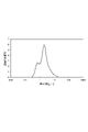
- FIG. 1 is a diagram showing an example of volume-based particle size distribution of silicon nitride powder measured with a particle size distribution measuring device using a laser diffraction/scattering method.
- the horizontal axis is the particle size [ ⁇ m] on a logarithmic scale, and the vertical axis is the frequency [% by volume].
- the particle size distribution in the present disclosure is measured according to the method described in JIS Z 8825:2013 "Particle Size Analysis-Laser Diffraction/Scattering Method".
- the particle size distribution measured without dispersion treatment before the measurement of the particle size distribution is referred to as "particle size distribution A".
- Particle size distribution A is measured while maintaining aggregated particles.
- Examples of dispersion treatment include those carried out as pretreatments for normal particle size distribution. Examples thereof include dispersion by ultrasonic waves, and mixing using a stirrer, a stirring blade, a spatula, or the like.
- the particle size distribution A For the measurement of the particle size distribution A, first, 60 mg of silicon nitride powder is weighed into a 500 mL container. A 20% aqueous solution (2 mL) of sodium hexametaphosphate and water (200 g) are blended with this as a dispersant to obtain a measurement sample. The particle size distribution A is measured using this measurement sample. For the measurement of the particle size distribution A, LS-13 320 (trade name) manufactured by Beckman Coulter is used. As measurement conditions, the particle refractive index is 2.2 and the solvent refractive index is 1.33.
- the particle size distribution A measured under the above conditions has a first peak 10 having an apex in the particle size range of less than 1 ⁇ m and a second peak 20 having an apex in the particle size range of 1 ⁇ m or more. That is, the particle size distribution A has a valley between the first peak 10 and the second peak 20 . Particle size distribution A consists of two peaks and a valley between them.
- a first peak 10 indicates the particle size of the primary particles of silicon nitride.
- the particle diameter d1 at the top of the first peak 10 may be 0.2-0.95 ⁇ m.
- the lower limit of the particle diameter d1 may be 0.3 ⁇ m, 0.4 ⁇ m, or 0.5 ⁇ m from the viewpoint of ease of production.
- the upper limit of the particle diameter d1 may be 0.9 ⁇ m, 0.8 ⁇ m, or 0.7 ⁇ m from the viewpoint of improving sinterability.
- the second peak 20 indicates the particle size of aggregated particles formed by aggregating primary particles.
- aggregated particles refers to particles that are not unaggregated even when the above dispersant is added.
- the particle diameter d2 at the apex of the second peak 20 may be greater than 1.5 ⁇ m and less than 4.0 ⁇ m.
- the lower limit of the particle diameter d2 may be 1.6 ⁇ m, 1.7 ⁇ m, or 1.8 ⁇ m from the viewpoint of improving sinterability.
- the upper limit of the particle diameter d2 may be 3.5 ⁇ m, 3.0 ⁇ m, or 2.5 ⁇ m from the viewpoint of improving sinterability.
- the ratio (d2/d1) of particle diameter d2 to particle diameter d1 may be 4 or less, or 3.5 or less. It may be 3 or less. As a result, the number of primary particles contained in the aggregated particles can be reduced, and the size of the aggregated particles can be reduced. Therefore, when slurry containing silicon nitride powder is prepared, the fluidity of the slurry can be further increased.
- the ratio (d2/d1) of the particle diameter d2 to the particle diameter d1 may be 1 or more, or 2 or more, from the viewpoint of sufficiently small primary particles.
- the area ratio of the first peak 10 to the entire particle size distribution A may be 10% or more, 15% or more, or 20% or more. Also, the area ratio of the first peak 10 to the entire particle size distribution A may be 45% or less, 40% or less, or 30% or less.
- the area ratio of the second peak 20 to the entire particle size distribution A may be 80% or less, 78% or less, or 76% or less. As a result, the proportion of agglomerated particles in the silicon nitride powder can be reduced, and the fluidity of the slurry can be further increased. From a similar point of view, the area ratio of the first peak 10 to the entire particle size distribution A may be 20% or more, 22% or more, or 24% or more. In the present disclosure, the area ratio of the first peak is the cumulative value of frequency in the particle size range of less than 1 ⁇ m, and the area ratio of the second peak is the cumulative value of frequency in the particle size range of 1 ⁇ m or more. The sum of the area ratios of the first peak 10 and the second peak 20 is 100%. The area ratio of the second peak 20 to the entire particle size distribution A may be 40% or more, or may be 50% or more, from the viewpoint of smooth production.
- the frequency at the top of the first peak 10 may be 1.00% by volume or more, may be 1.50% by volume or more, may be 1.75% by volume or more, or may be 2.00% by volume or more. may be 2.25% by volume or more.
- the frequency at the top of the first peak 10 may be 5.00 vol% or less, may be 4.50 vol% or less, may be 4.00 vol% or less, and may be 3.50 vol% or less. and may be 3.00% by volume or less.
- the frequency at the apex of the second peak 20 may be 4.00 vol% or more, 4.50 vol% or more, 5.00 vol% or more, 5.25 vol% or more. you can The frequency at the apex of the second peak 20 may be 8.00 vol% or less, may be 7.50 vol% or less, may be 7.00 vol% or less, and may be 6.50 vol% or less. may be 6.25% by volume or less.
- the average particle size (D50, median size) of the silicon nitride powder obtained from the particle size distribution A may be 1.0 to 2.5 ⁇ m.
- the average particle size is the particle size in the cumulative distribution of particle size distribution A when the integrated value from the small particle size reaches 50% of the total.
- the average particle size may be 1.2-1.9 ⁇ m, and may be 1.4-1.8 ⁇ m. This makes it possible to stably prepare a slurry having even better fluidity.
- the thermal conductivity and mechanical properties of the silicon nitride sintered body can be made to a higher level.
- D10 when the particle size when the integrated value from the small particle size reaches 10% of the total is D10, D10 may be 0.8 ⁇ m or less, and may be 0.7 ⁇ m or less. may be This can sufficiently improve the sinterability of the silicon nitride powder.
- the lower limit of D10 may be 0.2 ⁇ m or more from the viewpoint of ease of manufacture.
- D90 when the particle size when the integrated value from the small particle size reaches 90% of the total is D90, D90 may be 5.8 ⁇ m or less, and may be 5.0 ⁇ m or less. may be This makes it possible to further increase the fluidity of the slurry.
- the lower limit of D90 may be 3.0 ⁇ m or more from the viewpoint of ease of manufacture.
- the particle size distribution B in FIG. 1 is measured by dispersing the silicon nitride powder.
- the particle size distribution B is measured by dispersing the silicon nitride powder.
- 60 mg of silicon nitride powder is weighed into a 500 mL container.
- a 20% aqueous solution (2 mL) of sodium hexametaphosphate and water (200 g) are mixed with this as a dispersant to obtain a measurement sample.
- the container containing the water and the silicon nitride powder is set in an ultrasonic dispersion machine manufactured by Sharp Corporation, and ultrasonic dispersion is performed for 3 minutes.
- the particle size distribution is measured using the particle size distribution measuring apparatus used in the measurement of the particle size distribution A.
- the particle size distribution B is measured under the same measurement conditions as the particle size distribution A, except that the dispersion treatment described above is performed.
- the particle size distribution B measured under the above conditions has a third peak 30 having a peak in the particle size range of less than 1 ⁇ m and a fourth peak 40 having a peak in the particle size range of 1 ⁇ m or more. That is, the particle size distribution B has a valley between the third peak 30 and the fourth peak 40 .
- the difference between the second peak 20 and the fourth peak 40 is the frequency of deagglomerated particles among the agglomerated particles present before the ultrasonic treatment. Having the fourth peak 40 is not essential, and the fourth peak 40 may be absent. In this case, it means that most or all of the agglomerated particles contained in the silicon nitride powder were crushed into primary particles.
- the particle size distribution B consists of two peaks and a valley between them.
- a third peak 30 indicates the particle size of the primary particles of silicon nitride.
- the particle diameter d3 at the top of the third peak 30 may be 0.2-0.95 ⁇ m.
- the lower limit of the particle diameter d3 may be 0.3 ⁇ m, 0.4 ⁇ m, or 0.5 ⁇ m from the viewpoint of ease of production.
- the upper limit of the particle diameter d1 may be 0.9 ⁇ m, 0.8 ⁇ m, or 0.7 ⁇ m from the viewpoint of improving sinterability.
- the fourth peak 40 indicates the particle size of coarse particles that are not pulverized in the dispersion treatment.
- the particle diameter d4 at the apex of the fourth peak 40 may be greater than 1.5 ⁇ m and less than 4.0 ⁇ m.
- the lower limit of the particle diameter d4 may be 1.6 ⁇ m, 1.7 ⁇ m, or 1.8 ⁇ m from the viewpoint of improving sinterability.
- the upper limit of the particle diameter d4 may be 3.5 ⁇ m, 3.0 ⁇ m, or 2.5 ⁇ m from the viewpoint of improving sinterability.
- the area ratio of the fourth peak 40 to the entire particle size distribution B may be, for example, 60% or less.
- the area ratio of the third peak 30 to the entire particle size distribution B may be, for example, 40% or more.
- the area ratio of the third peak is the cumulative value of frequency in the particle size range of less than 1 ⁇ m
- the area ratio of the fourth peak is the cumulative value of frequency in the particle size range of 1 ⁇ m or more.
- the sum of the area ratios of the third peak 30 and the fourth peak 40 is 100%.
- the difference ( ⁇ 1) obtained by subtracting the area ratio of the fourth peak to the entire particle size distribution B from the area ratio of the second peak to the entire particle size distribution A may be 22% or less, and 20% or less. may be A small difference means that the ratio of agglomerated particles contained in the silicon nitride powder before dispersion treatment is low. Such silicon nitride powder can stably prepare a slurry having better fluidity.
- the difference ( ⁇ 2) when the area ratio of the first peak to the entire particle size distribution A is subtracted from the area ratio of the third peak to the entire particle size distribution B is 22% or less. It may be 20% or less.
- the difference ( ⁇ 1) may be 5% or more, or may be 10% or more, from the viewpoint of ease of manufacture. From a similar point of view, the difference ( ⁇ 2) may be 5% or more, or 10% or more.
- a slurry according to one embodiment contains silicon nitride powder and water.
- the viscosity (30 rpm) at 25° C. of the slurry containing the silicon nitride powder and water at a mass ratio of 1:1 may be 10 Pa s or less, 8 Pa s or less, or 6 Pa s or less. It may be 5 Pa ⁇ s or less.
- a slurry having such a low viscosity is excellent in dispersibility of the silicon nitride powder, which is a solid content. Therefore, when the silicon nitride sintered body is produced by the wet molding process, it is possible to sufficiently reduce variations in the properties of the silicon nitride sintered body. Therefore, a silicon nitride sintered body having high thermal conductivity and mechanical properties can be produced smoothly and stably.
- the viscosity (60 rpm) at 25° C. of the slurry containing silicon nitride powder and water at a mass ratio of 1:1 may be 6 Pa s or less, 5 Pa s or less, It may be 4 Pa ⁇ s or less, or may be 3 Pa ⁇ s or less.
- the viscosity (30 rpm) of the slurry at 25°C may be 1 Pa ⁇ s or more, or may be 2 Pa ⁇ s or more. From the same point of view, the viscosity (60 rpm) of the slurry at 25° C. may be 0.5 Pa ⁇ s or more, or 1 Pa ⁇ s or more.
- the viscosity of the slurry changes depending on the aggregation state of the primary particles of silicon nitride. That is, if the silicon nitride powder has a reduced content of agglomerated particles formed by aggregating primary particles of silicon nitride, the viscosity of the slurry can be lowered. Therefore, the compact can be produced smoothly. If a silicon nitride powder capable of reducing the viscosity of the slurry is used, variations in the properties of the silicon nitride sintered body can be sufficiently reduced even in a dry molding process. Therefore, it is possible to stably produce a silicon nitride sintered body having high thermal conductivity and mechanical properties in both wet and dry processes.
- Slurry viscosity in the present disclosure is measured by the following procedure. Water and silicon nitride powder are blended at a mass ratio of 1:1 and stirred with a stirrer until the viscosity becomes constant. This ensures a sufficiently uniform dispersion of the silicon nitride powder in the water.
- the viscosity of the prepared slurry is measured using a commercially available B-type viscometer. The viscosity is measured at 25° C. and at a predetermined rotation speed (30 rpm, 60 rpm, etc.). As the B-type viscometer, TVB-10 (trade name) manufactured by Toki Sangyo Co., Ltd. can be used.
- the method for producing a silicon nitride powder of this example includes a firing step of firing a silicon powder in an atmosphere containing nitrogen and at least one selected from the group consisting of hydrogen and ammonia to obtain a fired product; It has a pulverization step of dry-pulverizing a material to obtain a pulverized material, and a classification step of dry-classifying the pulverized material.
- silicon powder with a low oxygen concentration may be used.
- the oxygen concentration of the silicon powder may be, for example, 0.40% by mass or less, 0.30% by mass or less, or 0.20% by mass or less.
- the lower limit of the oxygen concentration of the silicon powder may be, for example, 0.10% by mass or 0.15% by mass.
- the silicon powder may have an oxygen concentration of, for example, 0.10 to 0.40% by mass. Incidentally, the oxygen concentration of the silicon powder can be measured by an infrared absorption method.
- the silicon powder is fired in a mixed atmosphere containing nitrogen and at least one selected from the group consisting of hydrogen and ammonia to obtain a fired product containing silicon nitride.
- the total content of hydrogen and ammonia in the mixed atmosphere may be, for example, 10-40% by volume based on the entire mixed atmosphere.
- the firing temperature may be, for example, 1100-1450°C, or 1200-1400°C.
- the firing time may be, for example, 30-100 hours.
- the fired product obtained in the firing step is dry-pulverized to obtain a pulverized product.
- the pulverization process may be divided into multiple stages such as coarse pulverization and fine pulverization.
- the milling process may include two stages, a ball milling process and a vibratory milling process.
- the filling rate of balls in the container in the ball milling process may be 30 to 70% by volume.
- the lower limit of the ball filling rate in the container may be, for example, 50% by volume or 60% by volume based on the volume of the container.
- the upper limit of the ball filling rate in the container may be, for example, 65% by volume based on the volume of the container.
- the grinding treatment time (grinding time) in the ball mill grinding step may be 5 to 15 hours, or may be 8 to 12 hours. As a result, the aggregated particles can be made sufficiently fine while suppressing excessive pulverization.
- the pulverized material obtained in the ball mill pulverization step may be further pulverized by the vibration mill pulverization step.
- the filling rate of the balls in the container in the vibratory milling process may be 50 to 80% by volume, or may be 60 to 75% by volume.
- the grinding treatment time (grinding time) in the vibration mill grinding step may be 8 to 20 hours, or may be 12 to 17 hours.
- the aggregated particles can be made sufficiently fine while suppressing excessive pulverization, and the ratio (d2/d1) of the particle diameter d2 to the particle diameter d1 can be adjusted.
- the difference ( ⁇ 1) obtained by subtracting the area ratio of the fourth peak from the area ratio of the second peak can be adjusted. For example, by increasing the time, the ratio (d2/d1) can be decreased and the difference ( ⁇ 1) can be decreased.
- the pulverized material obtained in the pulverization step is dry-classified to obtain a silicon nitride powder having a desired particle size distribution.
- a silicon nitride powder having a desired particle size distribution.
- at least a portion of aggregated particles can be excluded to increase the ratio of primary particles and increase the area ratio of the first peak.
- Dry classification can be performed by air classification or the like.
- the airflow classifier can be classified by using a whirling airflow type using secondary air.
- DS-10 trade name manufactured by Nippon Pneumatic Industry Co., Ltd. may be used.
- the primary air pressure (inlet pressure) may be, for example, 0.2-0.8 MPa, or 0.3-0.7 MPa.
- the primary air volume may be 1-5 m 3 /min, and may be 2-4 m 3 /min.
- the clearance of the secondary air intake may be 25-45 mm, and may be 30-40 mm.
- the ratio of aggregated particles on the fine powder side By increasing the primary air pressure within the above range, it is possible to reduce the ratio of aggregated particles on the fine powder side. That is, the area ratio of the second peak in the particle size distribution A of fine powder can be reduced. Further, within the above range, if the clearance of the secondary air intake is increased to increase the amount of air, the mixing ratio (powder/air amount) becomes smaller, and the ratio of aggregated particles on the fine powder side can be reduced. . That is, the area ratio of the second peak in the particle size distribution A of fine powder can be reduced.
- the ratio of the silicon nitride powder after classification (fine powder after removing coarse particles) to the total amount of pulverized material before the classification step may be 40 to 60% by mass, or 44 to 56% by mass. By lowering this ratio, the content of agglomerated particles in the fine powder can be further reduced. That is, it is possible to decrease the area ratio of the second peak and increase the area ratio of the first peak. On the other hand, if the ratio is increased, the area ratio of the second peak is increased, but the manufacturing cost of the silicon nitride powder can be reduced.
- the silicon nitride powder of the present embodiment can be produced through the above steps.
- the manufacturing method described above is an example, and is not limited to this.
- the silicon nitride powder of the present embodiment has reduced agglomerated particles, and is therefore excellent in sinterability. Therefore, silicon nitride powder may be used as a raw material for sintering.
- An embodiment of the method for producing a silicon nitride sintered body has a step of molding and firing the sintering raw material containing the silicon nitride powder described above.
- the raw material for sintering may contain an oxide-based sintering aid in addition to the silicon nitride powder.
- oxide-based sintering aids include Y 2 O 3 , MgO and Al 2 O 3 .
- the content of the oxide-based sintering aid in the raw material for sintering may be, for example, 3 to 10% by mass.
- the above sintering raw material is pressed with a molding pressure of, for example, 3.0 to 30 MPa to obtain a compact.
- the compact may be produced by uniaxial pressing or may be produced by CIP. Moreover, you may bake while shape
- the firing temperature may be 1860-2100°C, or 1880-2000°C.
- the firing time at the firing temperature may be 6 to 20 hours, or 8 to 16 hours.
- the heating rate to the firing temperature may be, for example, 1.0 to 10.0° C./hour.
- the obtained silicon nitride sintered body has reduced coarse grains and has a fine structure with excellent uniformity. Moreover, since it has a sufficiently dense structure, it is excellent in thermal conductivity and mechanical properties. In addition, since variation in particle size is reduced, variation in properties of the silicon nitride sintered body can be reduced.
- Example 1 A compact (bulk density: 1.4 g/cm 3 ) was produced using silicon powder. The obtained compact was placed in an electric furnace and fired at 1400° C. for 60 hours to produce a fired body containing silicon nitride. A mixed gas of nitrogen and hydrogen (a mixed gas in which N 2 and H 2 are mixed in a volume ratio of 80:20 in a standard state) was supplied as an atmosphere during firing. After roughly pulverizing the obtained sintered body, it was dry-pulverized with a ball mill. In the pulverization by the ball mill, the filling rate of the balls in the container was set to 60% by volume, and the pulverization time was set to 8 hours. Furthermore, the dry-pulverized material was dry-pulverized by a vibrating mill, and the filling rate of the balls to the container was set to 70% by volume, and the pulverization time was set to 15 hours.
- a mixed gas of nitrogen and hydrogen a mixed gas in which N 2 and H 2 are mixed in a volume ratio of 80:20 in
- the silicon nitride powder obtained by dry pulverization was classified using a classifier (trade name: DS-10, manufactured by Nippon Pneumatic Industry Co., Ltd.). Classification conditions were as follows. Primary air pressure: 0.6 MPa Primary air volume: 4 m 3 /min Secondary air intake clearance: 30mm
- Coarse particles were removed from the silicon nitride powder by classification.
- the mass ratio of the silicon nitride powder after classification to the total mass of the silicon nitride powder before classification was 44% by mass.
- the classified silicon nitride powder means a silicon nitride powder obtained by removing coarse particles (aggregated particles). The same applies to the following examples and comparative examples.
- Example 2 A silicon nitride powder was prepared in the same manner as in Example 1, except that the classification conditions were changed as follows. The mass ratio of the silicon nitride powder after classification to the total mass of the silicon nitride powder before classification was 56% by mass. Primary air pressure: 0.4 MPa Primary air volume: 3 m 3 /min Secondary air intake clearance: 40mm
- Example 1 A silicon nitride powder was prepared in the same manner as in Example 1, except that the classification conditions were changed as follows. The mass ratio of the silicon nitride powder after classification to the total mass of the silicon nitride powder before classification was 65% by mass. Primary air pressure: 0.1 MPa Primary air volume: 0.5 m 3 /min Secondary air intake clearance: 30mm
- Example 2 A silicon nitride powder was prepared in the same manner as in Example 1, except that the classification conditions were changed as follows. The mass ratio of the silicon nitride powder after classification to the total mass of the silicon nitride powder before classification was 62% by mass. Primary air pressure: 0.2 MPa Primary air volume: 1 m 3 /min Secondary air intake clearance: 20mm
- a 20% aqueous solution (2 mL) of sodium hexametaphosphate and water (200 g) were mixed with this as a dispersant to prepare a measurement sample.
- the measurement sample was set in a particle size distribution measuring device (manufactured by Beckman Coulter, trade name: LS-13 320) without performing an ultrasonic dispersion operation. Using this measurement device, the volume-based particle size distribution was measured. Particle size distribution A obtained by such measurements was as shown in FIGS.
- FIG. 2 shows the particle size distribution A of Example 1.
- 3 shows the particle size distribution A of Example 2.
- FIG. 4 shows the particle size distribution A of Comparative Example 1.
- FIG. 5 shows the particle size distribution A of Comparative Example 2.
- Table 1 shows the cumulative distribution of each particle size distribution A.
- the particle size distribution A of Examples 1 and 2 has a first peak having a peak in a particle size range of less than 1 ⁇ m and a second peak having a peak in a particle size range of 1 ⁇ m or more.
- the particle size d1 at the top of the first peak, the particle size d2 at the top of the second peak, the particle size ratio (d2/d1), and the frequency of the particle size d1 and the particle size d2 were as shown in Table 2.
- the area ratios of the first peak and the second peak to the entire particle size distribution A were as shown in Table 2, respectively.
- the particle size distribution A of Comparative Examples 1 and 2 did not have a peak in the particle size range of less than 1 ⁇ m.
- Particle size distribution A of Comparative Examples 1 and 2 had only a second peak having an apex in the particle size range of 1 ⁇ m or more.
- the column of the area ratio of the first peak in Table 2 shows the cumulative value of the frequency at which the particle diameter is less than 1 ⁇ m.
- Particle size distribution measurement was performed in the same procedure as “measurement of particle size distribution A” except that the agglomerated particles contained in the measurement sample were crushed into primary particles as described above.
- the cumulative distribution of particle size distribution B the particle size was measured when the integrated value from the small particle size reached 10%, 50% and 90% of the total.
- the respective particle sizes are shown in Table 3 as D10, D50 and D90.
- Particle size distribution B of Examples 1 and 2 like particle size distribution A, has a third peak having a peak in a particle size range of less than 1 ⁇ m and a fourth peak having a peak in a particle size range of 1 ⁇ m or more. had. Comparing particle size distribution A and particle size distribution B, in both Examples 1 and 2, the third peak was larger than the first peak, and the fourth peak was smaller than the second peak. From this, it was confirmed that the agglomerated particles were pulverized into primary particles by the dispersion treatment.
- the particle size distribution B of Comparative Examples 1 and 2 also has a third peak having a peak in a particle size range of less than 1 ⁇ m and a peak in a particle size range of 1 ⁇ m or more as the aggregated particles are crushed. It had a fourth peak with
- the difference ( ⁇ 1) obtained by subtracting the area ratio of the fourth peak from the area ratio of the second peak in the particle size distribution A was as shown in Table 4.
- This difference is the difference ( ⁇ 2) when the area ratio of the first peak (in Comparative Examples 1 and 2, the cumulative value of the frequency of particle diameters of less than 1 ⁇ m) is subtracted from the area ratio of the third peak in the particle size distribution B.
- ⁇ 2 when the area ratio of the first peak (in Comparative Examples 1 and 2, the cumulative value of the frequency of particle diameters of less than 1 ⁇ m) is subtracted from the area ratio of the third peak in the particle size distribution B.
- the silicon nitride powder of each example was able to reduce the viscosity of the slurry more than the silicon nitride powder of each comparative example.
- the silicon nitride powder as in each example it is possible to smoothly produce a silicon nitride sintered body having excellent thermal conductivity and mechanical properties and reduced variation in properties.
- a silicon nitride powder in which aggregation of primary particles of silicon nitride is sufficiently suppressed is provided. Also, containing such a silicon nitride powder provides a slurry having excellent fluidity. Further, by using such a silicon nitride powder, there is provided a method for producing a silicon nitride sintered body that is excellent in thermal conductivity and mechanical properties and capable of reducing variations in properties.
- A, B Particle size distribution, 10... 1st peak, 20... 2nd peak, 30... 3rd peak, 40... 4th peak.
Landscapes
- Chemical & Material Sciences (AREA)
- Engineering & Computer Science (AREA)
- Organic Chemistry (AREA)
- Ceramic Engineering (AREA)
- Manufacturing & Machinery (AREA)
- Materials Engineering (AREA)
- Structural Engineering (AREA)
- Inorganic Chemistry (AREA)
- Ceramic Products (AREA)
Priority Applications (1)
| Application Number | Priority Date | Filing Date | Title |
|---|---|---|---|
| JP2022533452A JP7171973B1 (ja) | 2021-03-30 | 2022-03-23 | 窒化ケイ素粉末、スラリー、及び窒化ケイ素焼結体の製造方法 |
Applications Claiming Priority (2)
| Application Number | Priority Date | Filing Date | Title |
|---|---|---|---|
| JP2021-057700 | 2021-03-30 | ||
| JP2021057700 | 2021-03-30 |
Publications (1)
| Publication Number | Publication Date |
|---|---|
| WO2022210214A1 true WO2022210214A1 (ja) | 2022-10-06 |
Family
ID=83459161
Family Applications (1)
| Application Number | Title | Priority Date | Filing Date |
|---|---|---|---|
| PCT/JP2022/013725 Ceased WO2022210214A1 (ja) | 2021-03-30 | 2022-03-23 | 窒化ケイ素粉末、スラリー、及び窒化ケイ素焼結体の製造方法 |
Country Status (2)
| Country | Link |
|---|---|
| JP (1) | JP7171973B1 (https=) |
| WO (1) | WO2022210214A1 (https=) |
Citations (4)
| Publication number | Priority date | Publication date | Assignee | Title |
|---|---|---|---|---|
| JP2002265276A (ja) * | 2001-03-07 | 2002-09-18 | Hitachi Metals Ltd | 窒化ケイ素粉末および窒化ケイ素焼結体 |
| CN102206082A (zh) * | 2011-03-03 | 2011-10-05 | 北方民族大学 | 一种制备亚微米氮化硅的方法 |
| JP2013203613A (ja) * | 2012-03-29 | 2013-10-07 | Ube Industries Ltd | 窒化ケイ素粉末の管理方法 |
| JP2016003157A (ja) * | 2014-06-16 | 2016-01-12 | 宇部興産株式会社 | 多結晶シリコンインゴット鋳造用鋳型の離型剤用窒化ケイ素粉末及びその製造方法、多結晶シリコンインゴット鋳造用鋳型の離型剤用窒化ケイ素粉末含有スラリー、ならびに多結晶シリコンインゴット鋳造用鋳型及びその製造方法 |
-
2022
- 2022-03-23 JP JP2022533452A patent/JP7171973B1/ja active Active
- 2022-03-23 WO PCT/JP2022/013725 patent/WO2022210214A1/ja not_active Ceased
Patent Citations (4)
| Publication number | Priority date | Publication date | Assignee | Title |
|---|---|---|---|---|
| JP2002265276A (ja) * | 2001-03-07 | 2002-09-18 | Hitachi Metals Ltd | 窒化ケイ素粉末および窒化ケイ素焼結体 |
| CN102206082A (zh) * | 2011-03-03 | 2011-10-05 | 北方民族大学 | 一种制备亚微米氮化硅的方法 |
| JP2013203613A (ja) * | 2012-03-29 | 2013-10-07 | Ube Industries Ltd | 窒化ケイ素粉末の管理方法 |
| JP2016003157A (ja) * | 2014-06-16 | 2016-01-12 | 宇部興産株式会社 | 多結晶シリコンインゴット鋳造用鋳型の離型剤用窒化ケイ素粉末及びその製造方法、多結晶シリコンインゴット鋳造用鋳型の離型剤用窒化ケイ素粉末含有スラリー、ならびに多結晶シリコンインゴット鋳造用鋳型及びその製造方法 |
Also Published As
| Publication number | Publication date |
|---|---|
| JP7171973B1 (ja) | 2022-11-15 |
| JPWO2022210214A1 (https=) | 2022-10-06 |
Similar Documents
| Publication | Publication Date | Title |
|---|---|---|
| JP5198121B2 (ja) | 炭化タングステン粉末、炭化タングステン粉末の製造方法 | |
| JPWO2019167879A1 (ja) | 窒化ケイ素粉末の製造方法 | |
| JPWO2011081103A1 (ja) | ジルコニア−アルミナ複合セラミック材料の製造方法、ジルコニア−アルミナ複合造粒粉、ジルコニアビーズ | |
| JP5637075B2 (ja) | ナノ複合材料の製造方法 | |
| JP2025143538A (ja) | 窒化ケイ素粉末、及び窒化ケイ素焼結体の製造方法 | |
| WO2003040060A1 (en) | Boron carbide based sintered compact and method for preparation thereof | |
| JP7187356B2 (ja) | 球状炭化ホウ素粉末の製造方法 | |
| TWI884245B (zh) | 氮化矽粉末、以及氮化矽燒結體之製造方法 | |
| WO2021200830A1 (ja) | 窒化ケイ素粉末、及び窒化ケイ素焼結体の製造方法 | |
| JP7171973B1 (ja) | 窒化ケイ素粉末、スラリー、及び窒化ケイ素焼結体の製造方法 | |
| JP7242972B2 (ja) | 窒化ケイ素粉末、及び窒化ケイ素焼結体の製造方法 | |
| WO2018070466A1 (ja) | 炭化タングステン粉末 | |
| JP7223918B1 (ja) | 窒化ケイ素粉末、及び窒化ケイ素焼結体の製造方法 | |
| JPH0782033A (ja) | セラミックス焼結体の製造方法及び製造装置 | |
| WO2018037846A1 (ja) | 炭窒化チタン粉末、及び炭窒化チタン粉末の製造方法 | |
| JP2006298711A (ja) | ZrO2質焼結体およびその製造方法、粉砕機用部材、粉砕機 | |
| WO2021049530A1 (ja) | 耐摩耗性アルミナ質焼結体 | |
| JP2699770B2 (ja) | 高充填性窒化ケイ素粉末及びその製造方法 | |
| JP2024010444A (ja) | 焼結用窒化ケイ素粉末 | |
| JP2008137838A (ja) | アルミナ粉末及びその製造方法 | |
| JP7640530B2 (ja) | 窒化ケイ素粉末、及び窒化ケイ素焼結体の製造方法 | |
| JP4965696B2 (ja) | 酸化物分散強化型白金合金の製造方法 | |
| WO2025205634A1 (ja) | 窒化ケイ素粉末、及びその製造方法 | |
| WO2025205635A1 (ja) | 窒化ケイ素粉末 | |
| WO2025205632A1 (ja) | 窒化ケイ素粉末、及びその製造方法 |
Legal Events
| Date | Code | Title | Description |
|---|---|---|---|
| ENP | Entry into the national phase |
Ref document number: 2022533452 Country of ref document: JP Kind code of ref document: A |
|
| 121 | Ep: the epo has been informed by wipo that ep was designated in this application |
Ref document number: 22780428 Country of ref document: EP Kind code of ref document: A1 |
|
| NENP | Non-entry into the national phase |
Ref country code: DE |
|
| 122 | Ep: pct application non-entry in european phase |
Ref document number: 22780428 Country of ref document: EP Kind code of ref document: A1 |