WO2022209632A1 - クラッチ制御装置 - Google Patents
クラッチ制御装置 Download PDFInfo
- Publication number
- WO2022209632A1 WO2022209632A1 PCT/JP2022/010033 JP2022010033W WO2022209632A1 WO 2022209632 A1 WO2022209632 A1 WO 2022209632A1 JP 2022010033 W JP2022010033 W JP 2022010033W WO 2022209632 A1 WO2022209632 A1 WO 2022209632A1
- Authority
- WO
- WIPO (PCT)
- Prior art keywords
- clutch
- actuator
- shaft
- transmission
- clutch device
- Prior art date
- Legal status (The legal status is an assumption and is not a legal conclusion. Google has not performed a legal analysis and makes no representation as to the accuracy of the status listed.)
- Ceased
Links
Images




Classifications
-
- F—MECHANICAL ENGINEERING; LIGHTING; HEATING; WEAPONS; BLASTING
- F16—ENGINEERING ELEMENTS AND UNITS; GENERAL MEASURES FOR PRODUCING AND MAINTAINING EFFECTIVE FUNCTIONING OF MACHINES OR INSTALLATIONS; THERMAL INSULATION IN GENERAL
- F16D—COUPLINGS FOR TRANSMITTING ROTATION; CLUTCHES; BRAKES
- F16D28/00—Electrically-actuated clutches
-
- F—MECHANICAL ENGINEERING; LIGHTING; HEATING; WEAPONS; BLASTING
- F16—ENGINEERING ELEMENTS AND UNITS; GENERAL MEASURES FOR PRODUCING AND MAINTAINING EFFECTIVE FUNCTIONING OF MACHINES OR INSTALLATIONS; THERMAL INSULATION IN GENERAL
- F16D—COUPLINGS FOR TRANSMITTING ROTATION; CLUTCHES; BRAKES
- F16D48/00—External control of clutches
- F16D48/06—Control by electric or electronic means, e.g. of fluid pressure
-
- F—MECHANICAL ENGINEERING; LIGHTING; HEATING; WEAPONS; BLASTING
- F16—ENGINEERING ELEMENTS AND UNITS; GENERAL MEASURES FOR PRODUCING AND MAINTAINING EFFECTIVE FUNCTIONING OF MACHINES OR INSTALLATIONS; THERMAL INSULATION IN GENERAL
- F16D—COUPLINGS FOR TRANSMITTING ROTATION; CLUTCHES; BRAKES
- F16D2500/00—External control of clutches by electric or electronic means
- F16D2500/10—System to be controlled
- F16D2500/102—Actuator
- F16D2500/1021—Electrical type
- F16D2500/1023—Electric motor
-
- F—MECHANICAL ENGINEERING; LIGHTING; HEATING; WEAPONS; BLASTING
- F16—ENGINEERING ELEMENTS AND UNITS; GENERAL MEASURES FOR PRODUCING AND MAINTAINING EFFECTIVE FUNCTIONING OF MACHINES OR INSTALLATIONS; THERMAL INSULATION IN GENERAL
- F16D—COUPLINGS FOR TRANSMITTING ROTATION; CLUTCHES; BRAKES
- F16D2500/00—External control of clutches by electric or electronic means
- F16D2500/10—System to be controlled
- F16D2500/11—Application
- F16D2500/1107—Vehicles
- F16D2500/1117—Motorcycle
-
- F—MECHANICAL ENGINEERING; LIGHTING; HEATING; WEAPONS; BLASTING
- F16—ENGINEERING ELEMENTS AND UNITS; GENERAL MEASURES FOR PRODUCING AND MAINTAINING EFFECTIVE FUNCTIONING OF MACHINES OR INSTALLATIONS; THERMAL INSULATION IN GENERAL
- F16D—COUPLINGS FOR TRANSMITTING ROTATION; CLUTCHES; BRAKES
- F16D2500/00—External control of clutches by electric or electronic means
- F16D2500/30—Signal inputs
- F16D2500/302—Signal inputs from the actuator
- F16D2500/3022—Current
-
- F—MECHANICAL ENGINEERING; LIGHTING; HEATING; WEAPONS; BLASTING
- F16—ENGINEERING ELEMENTS AND UNITS; GENERAL MEASURES FOR PRODUCING AND MAINTAINING EFFECTIVE FUNCTIONING OF MACHINES OR INSTALLATIONS; THERMAL INSULATION IN GENERAL
- F16D—COUPLINGS FOR TRANSMITTING ROTATION; CLUTCHES; BRAKES
- F16D2500/00—External control of clutches by electric or electronic means
- F16D2500/30—Signal inputs
- F16D2500/306—Signal inputs from the engine
- F16D2500/3061—Engine inlet air flow rate
-
- F—MECHANICAL ENGINEERING; LIGHTING; HEATING; WEAPONS; BLASTING
- F16—ENGINEERING ELEMENTS AND UNITS; GENERAL MEASURES FOR PRODUCING AND MAINTAINING EFFECTIVE FUNCTIONING OF MACHINES OR INSTALLATIONS; THERMAL INSULATION IN GENERAL
- F16D—COUPLINGS FOR TRANSMITTING ROTATION; CLUTCHES; BRAKES
- F16D2500/00—External control of clutches by electric or electronic means
- F16D2500/30—Signal inputs
- F16D2500/306—Signal inputs from the engine
- F16D2500/3065—Torque of the engine
-
- F—MECHANICAL ENGINEERING; LIGHTING; HEATING; WEAPONS; BLASTING
- F16—ENGINEERING ELEMENTS AND UNITS; GENERAL MEASURES FOR PRODUCING AND MAINTAINING EFFECTIVE FUNCTIONING OF MACHINES OR INSTALLATIONS; THERMAL INSULATION IN GENERAL
- F16D—COUPLINGS FOR TRANSMITTING ROTATION; CLUTCHES; BRAKES
- F16D2500/00—External control of clutches by electric or electronic means
- F16D2500/30—Signal inputs
- F16D2500/306—Signal inputs from the engine
- F16D2500/3067—Speed of the engine
-
- F—MECHANICAL ENGINEERING; LIGHTING; HEATING; WEAPONS; BLASTING
- F16—ENGINEERING ELEMENTS AND UNITS; GENERAL MEASURES FOR PRODUCING AND MAINTAINING EFFECTIVE FUNCTIONING OF MACHINES OR INSTALLATIONS; THERMAL INSULATION IN GENERAL
- F16D—COUPLINGS FOR TRANSMITTING ROTATION; CLUTCHES; BRAKES
- F16D2500/00—External control of clutches by electric or electronic means
- F16D2500/30—Signal inputs
- F16D2500/308—Signal inputs from the transmission
- F16D2500/30806—Engaged transmission ratio
-
- F—MECHANICAL ENGINEERING; LIGHTING; HEATING; WEAPONS; BLASTING
- F16—ENGINEERING ELEMENTS AND UNITS; GENERAL MEASURES FOR PRODUCING AND MAINTAINING EFFECTIVE FUNCTIONING OF MACHINES OR INSTALLATIONS; THERMAL INSULATION IN GENERAL
- F16D—COUPLINGS FOR TRANSMITTING ROTATION; CLUTCHES; BRAKES
- F16D2500/00—External control of clutches by electric or electronic means
- F16D2500/30—Signal inputs
- F16D2500/31—Signal inputs from the vehicle
- F16D2500/3108—Vehicle speed
-
- F—MECHANICAL ENGINEERING; LIGHTING; HEATING; WEAPONS; BLASTING
- F16—ENGINEERING ELEMENTS AND UNITS; GENERAL MEASURES FOR PRODUCING AND MAINTAINING EFFECTIVE FUNCTIONING OF MACHINES OR INSTALLATIONS; THERMAL INSULATION IN GENERAL
- F16D—COUPLINGS FOR TRANSMITTING ROTATION; CLUTCHES; BRAKES
- F16D2500/00—External control of clutches by electric or electronic means
- F16D2500/30—Signal inputs
- F16D2500/31—Signal inputs from the vehicle
- F16D2500/3108—Vehicle speed
- F16D2500/3109—Vehicle acceleration
-
- F—MECHANICAL ENGINEERING; LIGHTING; HEATING; WEAPONS; BLASTING
- F16—ENGINEERING ELEMENTS AND UNITS; GENERAL MEASURES FOR PRODUCING AND MAINTAINING EFFECTIVE FUNCTIONING OF MACHINES OR INSTALLATIONS; THERMAL INSULATION IN GENERAL
- F16D—COUPLINGS FOR TRANSMITTING ROTATION; CLUTCHES; BRAKES
- F16D2500/00—External control of clutches by electric or electronic means
- F16D2500/50—Problem to be solved by the control system
- F16D2500/502—Relating the clutch
- F16D2500/50203—Transition between manual and automatic control of the clutch
-
- F—MECHANICAL ENGINEERING; LIGHTING; HEATING; WEAPONS; BLASTING
- F16—ENGINEERING ELEMENTS AND UNITS; GENERAL MEASURES FOR PRODUCING AND MAINTAINING EFFECTIVE FUNCTIONING OF MACHINES OR INSTALLATIONS; THERMAL INSULATION IN GENERAL
- F16D—COUPLINGS FOR TRANSMITTING ROTATION; CLUTCHES; BRAKES
- F16D2500/00—External control of clutches by electric or electronic means
- F16D2500/70—Details about the implementation of the control system
- F16D2500/704—Output parameters from the control unit; Target parameters to be controlled
- F16D2500/70402—Actuator parameters
- F16D2500/70408—Torque
-
- F—MECHANICAL ENGINEERING; LIGHTING; HEATING; WEAPONS; BLASTING
- F16—ENGINEERING ELEMENTS AND UNITS; GENERAL MEASURES FOR PRODUCING AND MAINTAINING EFFECTIVE FUNCTIONING OF MACHINES OR INSTALLATIONS; THERMAL INSULATION IN GENERAL
- F16D—COUPLINGS FOR TRANSMITTING ROTATION; CLUTCHES; BRAKES
- F16D2500/00—External control of clutches by electric or electronic means
- F16D2500/70—Details about the implementation of the control system
- F16D2500/704—Output parameters from the control unit; Target parameters to be controlled
- F16D2500/70452—Engine parameters
- F16D2500/70458—Engine torque
Definitions
- the present invention relates to a clutch control device.
- This application claims priority based on Japanese Patent Application No. 2021-062275 filed in Japan on March 31, 2021, the content of which is incorporated herein.
- the clutch device can be driven only to the release side (disengagement side).
- a clutch spring having a large load is used in a normally closed clutch device.
- the present invention has been made in view of the above circumstances, and an object of the present invention is to efficiently configure an automatic clutch system in a clutch control device that controls the engagement and disengagement of a clutch device.
- one aspect of the present invention comprises a clutch device (26) for connecting and disconnecting power transmission between a prime mover (13) and an output target (21), and the clutch device (26).
- a clutch actuator (50) for outputting a drive force for actuation; and a drive mechanism (38) for receiving the drive force of the clutch actuator (50) to operate the clutch device (26), wherein the drive mechanism (38) can apply driving force to the clutch device (26) in both the disconnecting direction and the connecting direction.
- the drive mechanism between the clutch actuator and the clutch device can apply the drive force to the clutch device in both the disengagement direction and the connection direction, resulting in the following effects.
- the clutch actuator required for disengaging the clutch under normal conditions can be suppressed as compared with the case of using a clutch spring having a large load.
- the automatic clutch system can be efficiently configured, such as by reducing the size and weight of the clutch actuator.
- the clutch actuator (50) may apply the driving force in the clutch connecting direction to the clutch device (26) according to the operating state of the prime mover (13). According to this configuration, the clutch connection state corresponding to the output of the prime mover is maintained while suppressing the capacity of the clutch device. This can reduce costs.
- the clutch device (26) comprises a spring member (37) that generates a pressing force in the direction of clutch engagement, and the clutch actuator (50) operates only under predetermined operating conditions of the prime mover (13).
- a driving force in the clutch connecting direction may be applied to the clutch device (26).
- the clutch actuator applies the driving force to the clutch device in addition to the urging force of the spring member only under a predetermined operating condition of the prime mover (for example, when the output of the prime mover is high). Therefore, the operation of the actuator can be suppressed as much as possible.
- the clutch control device is applied to a vehicle (1), and the clutch actuator (50) applies a driving force in a clutch engagement direction to the clutch device (1) when accelerating the vehicle (1). 26).
- the drive mechanism (38) includes a first transmission member (62) on the side of the clutch actuator (50) and a second transmission member (39) on the side of the clutch device (26),
- the first transmission member (62) may be in constant engagement with the second transmission member (39) with mechanical meshing.
- the first transmission member on the clutch actuator side and the second transmission member on the clutch device side in the drive mechanism are always meshed with each other. As a result, driving forces in the disengagement direction and the connection direction can be easily applied to the clutch device by forward and reverse driving of the clutch actuator.
- the drive mechanism (38) constitutes a rack and pinion that converts the rotational motion of the first transmission member (62) into the reciprocating motion of the second transmission member (39),
- a pinion gear (38a) included in the mechanism (38) may be fan-shaped when viewed in the axial direction. According to this configuration, the drive mechanism is simply configured by a rack and pinion.
- the pinion gear of the driving mechanism is a fan-shaped gear with a part notched in the circumferential direction. As a result, it is possible to reduce the size of the drive mechanism.
- the clutch actuator (50) includes a drive source (52) that outputs the drive force, and a transmission mechanism (51) that interlocks the drive source (52) and the clutch device (26).
- the drive source (52) and the first transmission member (62), which is the output member of the transmission mechanism (51), are arranged in a first direction, and the input member of the clutch device (26). may be disposed between the drive source (52) and the first transmission member (62) in the first direction.
- the input member (second transmission member) of the clutch device is placed between the drive source of the clutch actuator and the output member (first transmission member), thereby providing the following effects. That is, generally, the input member is arranged in the axial center of the clutch device.
- a drive source and an output member of the clutch actuator are distributed and arranged on both sides of the input member in the first direction.
- an automatic clutch system can be efficiently configured in a clutch control device that controls connection and disconnection of a clutch device.
- FIG. 2 is a cross-sectional view of the transmission and change mechanism of the motorcycle; 2 is a block diagram of the transmission system of the motorcycle; FIG. FIG. 4 is an explanatory diagram showing transitions of clutch control modes of the motorcycle; FIG. 2 is a V arrow view of FIG. 1 and shows an axial view of the clutch actuator.
- FIG. 4 is a developed cross-sectional view along the axial direction of the clutch actuator;
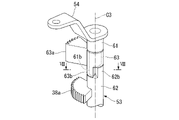
- FIG. 4 is a perspective view of a release shaft that operates a clutch device;
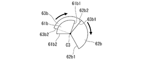
- FIG. 8 is a cross-sectional view taken along line VIII-VIII of FIG. 7;
- FIG. 9 is a cross-sectional view corresponding to FIG.
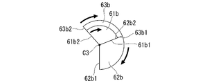
- FIG. 8 showing the action of the release shaft in the half-clutch region, and showing the drive by the clutch actuator
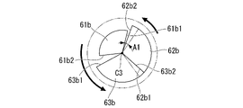
- FIG. 9 is a cross-sectional view corresponding to FIG. 8 showing the action of the release shaft in the half-clutch region, and showing manual intervention.
- FIG. 8 is a cross-sectional view corresponding to FIG. 7 , showing a state in which the clutch actuator is driven in reverse to urge the clutch device in the connecting direction
- FIG. 7 is a cross-sectional view corresponding to FIG. 6 showing a state in which the clutch actuator is attached to the right cover;
- the present embodiment is applied to a motorcycle 1 as an example of a saddle type vehicle.
- a front wheel 2 of the motorcycle 1 is supported by lower ends of a pair of left and right front forks 3 .
- Upper portions of the left and right front forks 3 are supported by a head pipe 6 at the front end of the body frame 5 via a steering stem 4 .
- a bar-type steering handle 4a is attached to the top bridge of the steering stem 4. As shown in FIG.
- the vehicle body frame 5 includes a head pipe 6, a main frame 7 extending downward and rearward from the head pipe 6 at the center in the vehicle width direction (left-right direction), a pivot frame 8 provided below the rear end of the main frame 7, and a main frame.
- a seat frame 9 connected to the rear of the frame 7 and the pivot frame 8 is provided.
- a front end portion of a swing arm 11 is pivotally supported on the pivot frame 8 so as to be able to swing.
- a rear wheel 12 of the motorcycle 1 is supported at the rear end of the swing arm 11 .
- a fuel tank 18 is supported above the left and right main frames 7 .
- a front seat 19 and a rear seat 19 a are supported behind the fuel tank 18 and above the seat frame 9 .
- knee grip portions 18a recessed inward in the vehicle width direction are formed.
- the left and right knee grip portions 18a are formed so as to match the following portions.
- the part is the inside of the left and right knees of the driver seated on the front seat 19 .
- Steps 18 b are supported on both left and right sides below the front seat 19 . On step 18b, the driver puts his/her foot from the ankle on.
- a power unit PU including the prime mover of the motorcycle 1 is suspended below the main frame 7 .
- the power unit PU integrally has an engine (internal combustion engine, prime mover) 13 located on the front side thereof and a transmission 21 located on the rear side thereof.
- the engine 13 is, for example, a multi-cylinder engine in which the rotation axis of the crankshaft 14 extends in the left-right direction (vehicle width direction).
- the engine 13 has a cylinder 16 erected above the front portion of the crankcase 15 .
- a rear part of the crankcase 15 is a transmission case 17 that accommodates the transmission 21 .
- a right cover 17 a that extends over the right side of the transmission case 17 is attached to the right side of the crankcase 15 .
- the right cover 17 a also serves as a clutch cover that covers the clutch device 26 .
- Power unit PU is linked to rear wheel 12 via, for example, a chain transmission mechanism (not shown).
- the transmission 21 is a stepped transmission.
- the transmission 21 has a main shaft 22 , a counter shaft 23 , and a transmission gear group 24 straddling both shafts 22 , 23 .
- Countershaft 23 constitutes an output shaft of transmission 21 and thus power unit PU.
- a left end portion of the countershaft 23 projects to the rear left side of the transmission case 17 and is connected to the rear wheel 12 via the chain type transmission mechanism.
- the main shaft 22 and countershaft 23 of the transmission 21 are arranged behind the crankshaft 14 .
- a clutch device 26 is coaxially arranged at the right end of the main shaft 22 .
- the clutch device 26 connects and disconnects power transmission between the crankshaft 14 of the engine 13 and the main shaft 22 of the transmission 21 .
- the clutch device 26 is engaged and disengaged by at least one of the operation of a clutch operator (for example, a clutch lever not shown) by the passenger and the operation of a clutch actuator 50 which will be described in detail later.
- the clutch device 26 is, for example, a wet multi-plate clutch, a so-called normally closed clutch. Rotational power of the crankshaft 14 is transmitted to the main shaft 22 via the clutch device 26 and transmitted from the main shaft 22 to the countershaft 23 via an arbitrary gear pair of the transmission gear group 24 .
- a drive sprocket 27 of the chain transmission mechanism is attached to the left end portion of the countershaft 23 that protrudes to the rear left side of the crankcase 15 .
- a change mechanism 25 for switching the gear pair of the transmission gear group 24 is accommodated.
- the change mechanism 25 has a hollow cylindrical shift drum 32 parallel to the shafts 22 and 23 .
- the change mechanism 25 operates the plurality of shift forks 32a. This operation is performed according to the pattern of lead grooves formed on the outer circumference of the shift drum 32 .
- the change mechanism 25 switches the gear pair used for power transmission between the shafts 22 and 23 in the transmission gear group 24 .
- the motorcycle 1 only the shift operation of the transmission 21 (foot operation of a shift pedal (not shown)) is performed by the driver, and the connection/disengagement operation of the clutch device 26 is electrically controlled according to the operation of the shift pedal. automatically. That is, the motorcycle 1 employs a so-called semi-automatic transmission system (automatic clutch type transmission system).
- the transmission system 30 includes a clutch actuator 50, an ECU 40 (Electronic Control Unit), various sensors 41-46, and various devices 47, 48, 50.
- the ECU 40 controls the operation of the ignition device 47 and the fuel injection device 48 and also controls the operation of the clutch actuator 50 .
- This control is based on detection information from the acceleration sensor 41, the gear position sensor 42, and the shift load sensor 43 (for example, a torque sensor), as well as various vehicle data from the throttle opening sensor 44, the vehicle speed sensor 45, the engine speed sensor 46, and the like. This is done based on state detection information and the like.
- the acceleration sensor 41 detects the behavior of the vehicle body.
- a gear position sensor 42 detects a gear position from the rotational angle of the shift drum 32 .
- the shift load sensor 43 detects the operating torque input to the shift spindle 31 (see FIG. 2) of the change mechanism 25 .
- a throttle opening sensor 44 detects the throttle opening.
- a vehicle speed sensor 45 detects the vehicle speed.
- An engine speed sensor 46 detects the engine speed.
- the clutch actuator 50 controls the operating torque applied to the release shaft 53 in order to connect and disconnect the clutch device 26.
- the clutch actuator 50 includes an electric motor 52 (hereinafter simply referred to as the motor 52 ) as a drive source and a speed reduction mechanism 51 that transmits the drive force of the motor 52 to the release shaft 53 .
- the ECU 40 calculates the following current values based on a preset calculation program.
- the current value is the value of the current supplied to the motor 52 to connect and disconnect the clutch device 26 .
- the current supplied to the motor 52 is obtained from the correlation with the torque that the motor 52 is caused to output.
- the target torque of the motor 52 is proportional to the operating torque applied to the release shaft 53 (driven clutch lever torque, which will be described later).
- a current value supplied to the motor 52 is detected by a current sensor 40 b included in the ECU 40 .
- the operation of the clutch actuator 50 is controlled according to the change in the detected value.
- the clutch actuator 50 will be detailed later.
- the clutch device 26 of the embodiment is a multi-plate clutch in which a plurality of clutch plates 35 are laminated in the axial direction, and is a wet clutch arranged in an oil chamber inside the right cover 17a.
- the clutch device 26 includes a clutch outer 33 , a clutch center 34 and a plurality of clutch plates 35 .
- the clutch outer 33 is driven by constant transmission of rotational power from the crankshaft 14 .
- the clutch center 34 is arranged inside the clutch outer 33 and supported by the main shaft 22 so as to be integrally rotatable.
- a plurality of clutch plates 35 are laminated between the clutch outer 33 and the clutch center 34 to frictionally engage them.
- a pressure plate 36 having substantially the same diameter as the clutch plates 35 is arranged on the right side (outside in the vehicle width direction) of the laminated clutch plates 35 .
- the pressure plate 36 receives the elastic load of the clutch spring 37 and is urged leftward, and presses (frictionally engages) the stacked clutch plates 35 with each other.
- the clutch device 26 enters a connected state in which power can be transmitted.
- the clutch device 26 is a normally closed clutch that is normally connected when there is no external input.
- the pressure contact (frictional engagement) is released by operating a release mechanism (drive mechanism) 38 inside the right cover 17a.
- the release mechanism 38 is a mechanism that operates the clutch device 26 in the disconnecting direction.
- the release mechanism 38 is also a mechanism that biases the clutch device 26 in the connecting direction by reverse driving of the clutch actuator 50 .
- the release mechanism 38 is operated by at least one of the operation of a clutch lever (not shown) by the passenger and the application of torque by forward rotation of the clutch actuator 50 .
- the release mechanism 38 includes a lifter shaft 39 and a release shaft 53.
- the lifter shaft 39 is axially reciprocally held within the right side of the main shaft 22 .
- the release shaft 53 is arranged so that its axial direction is perpendicular to the lifter shaft 39, and is held on the outer side of the right cover 17a so as to be rotatable about its axis.
- line C3 indicates the central axis of the release shaft 53 extending in the vertical direction
- line C4 indicates the central axis of the lifter shaft 39 perpendicular to the release shaft 53.
- the lifter shaft 39 is arranged below the speed reduction mechanism 51 .
- the release shaft 53 is tilted rearward in the axial direction (see FIG. 1) so that the upper side is positioned rearward with respect to the vertical direction when viewed in the axial direction of the main shaft 22 (side view of the vehicle).
- An upper portion of the release shaft 53 protrudes outside the right cover 17a, and a driven clutch lever 54 is attached to the upper portion of the release shaft 53 so as to rotate integrally therewith.
- the driven clutch lever 54 is connected to the clutch lever via an operation cable (not shown).
- a drive gear 38a is provided at a lower portion of the release shaft 53 located inside the right cover 17a so as to be rotatable therewith.
- the drive gear 38a is a sector gear centered on the release shaft 53. As shown in FIG.
- the drive gear 38 a is provided so as to extend forward of the release shaft 53 .
- a lifter shaft 39 is arranged in front of the drive gear 38a.
- a rear portion of the lifter shaft 39 is formed with a rack gear 39a having gear teeth arranged in the axial direction.
- the drive gear 38a functions as a pinion gear that meshes with the rack gear 39a.
- the drive gear 38a and the rack gear 39a constitute a rack and pinion. This rack and pinion causes the lifter shaft 39 to reciprocate as the release shaft 53 rotates.
- the lifter shaft 39 is connected to the pressure plate 36 of the clutch device 26 via a spring washer 36a (see FIG. 11).
- the lifter shaft 39 is integrally configured to reciprocate with the pressure plate 36 . Therefore, when the lifter shaft 39 moves rightward, the pressure plate 36 moves (lifts) rightward against the biasing force of the clutch spring 37 . As a result, the clutch device 26 releases the frictional engagement between the laminated clutch plates 35 . As a result, the normally closed clutch device 26 is brought into a disengaged state in which power cannot be transmitted.
- the lifter shaft 39 moves leftward, the pressure plate 36 moves rightward by the deflection of the spring washer 36a.
- the spring washer 36a presses the pressure plate 36 rightward. Thereby, the frictional engagement between the clutch plates 35 is strengthened. That is, the clutch capacity of the normally closed clutch device 26 is increased.
- the clutch control device 40A of this embodiment has three clutch control modes.
- the clutch control mode has an auto mode M1 for automatic control, a manual mode M2 for manual operation, and a manual intervention mode M3 for temporary manual operation.
- the clutch control mode appropriately transitions between the three modes according to the operation of the clutch control mode changeover switch 49 (see FIG. 3) and the clutch operator.
- a target including the manual mode M2 and the manual intervention mode M3 is referred to as a manual system M2A.
- the auto mode M1 is a mode in which the clutch device 26 is controlled by calculating a clutch capacity suitable for the running state in accordance with automatic start/shift control.
- the manual mode M2 is a mode in which the clutch capacity is calculated and the clutch device 26 is controlled according to the clutch operation instruction from the passenger.
- the manual intervention mode M3 is a temporary manual operation mode in which a clutch operation instruction from the passenger is received during the automatic mode M1, the clutch capacity is calculated from the clutch operation instruction, and the clutch device 26 is controlled. It should be noted that, during the manual intervention mode M3, for example, if the occupant stops operating the clutch operator (completely released state) for a specified period of time, the automatic mode M1 may be set to return.
- the clutch control device 40A starts control from the clutch-on state (engagement state) in auto mode M1. Further, the clutch control device 40A is set to return to the clutch-on state in the auto mode M1 when the engine 13 is stopped (when the system is off). In the normally closed clutch device 26, there is no need to supply power to the motor 52 of the clutch actuator 50 when the clutch is on. On the other hand, power supply to the motor 52 is maintained in the clutch-off state (disconnected state) of the clutch device 26 .
- Auto mode M1 basically performs clutch control automatically.
- Auto mode M1 enables the motorcycle 1 to run without lever operation.
- the clutch capacity is controlled based on the throttle opening, engine speed, vehicle speed, shift sensor output, and the like.
- the motorcycle 1 can be started only by operating the throttle without engine stall (engine stop or engine stall).
- the motorcycle 1 can be shifted only by a shift operation.
- the automatic mode M1 is switched to the manual intervention mode M3 when the passenger grips the clutch lever. Thereby, it is possible to arbitrarily disengage the clutch device 26 .
- the passenger can operate the lever to control the clutch capacity (that is, the clutch device 26 can be connected and disconnected).
- the auto mode M1 and the manual mode M2 are mutually switchable. This switching is performed, for example, by operating the clutch control mode switching switch 49 (see FIG. 3) while the motorcycle 1 is stopped and the transmission 21 is in neutral.
- the clutch control device 40A may include an indicator that indicates that the lever operation is effective when transitioning to the manual system M2A (manual mode M2 or manual intervention mode M3).
- clutch control is basically performed manually.
- the clutch capacity can be controlled according to the operating angle of the clutch lever (and thus the operating angle of the driven clutch lever 54). Thereby, it is possible to control the connection/disengagement of the clutch device 26 according to the passenger's intention.
- clutch control can automatically intervene when shift operation is performed without clutch operation.
- the operating angle of the driven clutch lever 54 will be referred to as the driven clutch lever operating angle.
- the clutch actuator 50 automatically connects and disconnects the clutch device 26 .
- manual clutch operation is performed on the clutch lever, so that manual operation can be temporarily intervened in the automatic control of the clutch device 26 (manual intervention mode M3).
- a clutch lever (not shown) as a manual clutch operator is attached to the base end side (inner side in the vehicle width direction) of the left grip of the steering handle 4a.
- the clutch lever is connected to a driven clutch lever 54 attached to a release shaft 53 of the clutch device 26 via an operating cable (not shown).
- the driven clutch lever 54 is attached to an upper end portion of the release shaft 53 that protrudes upward from the right cover 17a so as to rotate integrally therewith.
- the handle switch attached to the steering handle 4a is provided with the clutch control mode changeover switch 49 (see FIG. 3). This allows the occupant to easily switch the clutch control mode during normal driving.
- a clutch actuator 50 is attached to the rear upper portion of the right cover 17a on the right side of the crankcase 15.
- the clutch actuator 50 includes a motor 52 and a speed reduction mechanism 51.
- the motor 52 is, for example, a DC motor, and is arranged, for example, in parallel with the release shaft 53 in the axial direction.
- the motor 52 is arranged so that the drive shaft 55 protrudes upward.
- the reduction mechanism 51 transmits the driving force of the motor 52 to the release shaft 53 .
- multiple (two) motors 52 are provided for a single clutch actuator 50 .
- the motor 52 located on the vehicle front side of the clutch actuator 50 is referred to as a first motor 521
- the motor 52 located on the vehicle rear side and vehicle width direction inner side with respect to the first motor 521 is referred to as a second motor 522 .
- Lines C01 and C02 in the figure indicate central axes (drive axes) of the motors 521 and 522, respectively.
- both motors 521 and 522 may be collectively referred to as motor 52 .
- both axes C01 and C02 may be collectively referred to as axis C0.
- the deceleration mechanism 51 decelerates the rotational power output from the motor 52 and transmits it to the release shaft 53 .
- the reduction mechanism 51 includes, for example, a gear train axially parallel to the release shaft 53 .
- the reduction mechanism 51 includes a drive gear 55a, a first idle gear 57a, a first small diameter gear 57b, a second idle gear 58a, a second small diameter gear 58b, a driven gear 63a, and a gear case 59.
- the drive gear 55a is provided integrally with the drive shaft 55 of each motor 521,522.
- Each drive gear 55a meshes with the first idle gear 57a.
- the first small diameter gear 57b is provided coaxially with the first idle gear 57a.
- the second idle gear 58a meshes with the first small diameter gear 57b.
- the second small diameter gear 58b is provided coaxially with the second idle gear 58a.
- the driven gear 63a meshes with the second small diameter gear 58b.
- the gear case 59 accommodates each gear.
- the first idle gear 57a and the first small diameter gear 57b are rotatably supported by the first support shaft 57c.
- the first idle gear 57a, the first small diameter gear 57b and the first support shaft 57c constitute the first idle shaft 57.
- the second idle gear 58a and the second small-diameter gear 58b are rotatably supported by a second support shaft 58c.
- the second idle gear 58a, the second small diameter gear 58b and the second support shaft 58c constitute a second idle shaft 58.
- the first support shaft 57c and the second support shaft 58c are rotatably supported by the gear case 59, respectively.
- the second idle gear 58a is a sector gear centered on the second support shaft 58c.
- the second idle gear 58a is provided so as to extend forward and outward in the vehicle width direction of the second support shaft 58c.
- line C1 indicates the center axis of the first idle shaft 57
- line C2 indicates the center axis of the second idle shaft 58, respectively.
- the driven gear 63a is provided on the release shaft 53 so as to be integrally rotatable.
- the driven gear 63 a is a sector gear centered on the release shaft 53 .
- the driven gear 63 a is provided so as to extend forward of the release shaft 53 .
- a gear on the downstream side of the reduction mechanism 51 has a small rotation angle. Therefore, the second idle gear 58a and the driven gear 63a can be fan-shaped gears with a small rotation angle.
- a system is configured in which the clutch actuator 50 directly connects and disconnects the clutch device 26 .
- Each gear is a flat spur gear with reduced thickness in the axial direction
- the gear case 59 is also formed in a flat shape with reduced thickness in the axial direction. This makes the speed reduction mechanism 51 less noticeable when viewed from the side of the vehicle.
- a first rotation angle sensor 57d and a second rotation angle sensor 58d are provided on the upper surface side of the gear case 59 .
- a first rotation angle sensor 57d and a second rotation angle sensor 58d are connected to one end of each of the first idle shaft 57 and the second idle shaft 58 to detect their rotation angles.
- the motor 52 is arranged to protrude downward from the front of the gear case 59 .
- the clutch actuator 50 is arranged such that the motor 52 and the release shaft 53 are aligned in the longitudinal direction of the vehicle.
- the lifter shaft 39 of the clutch device 26 is arranged between the motor 52 and the release shaft 53 (at an intermediate position of the clutch actuator 50) in the longitudinal direction of the vehicle.
- the lifter shaft 39 is arranged in the axial center of the clutch device 26, and the clutch actuator 50 is arranged on both front and rear sides of the axial center of the clutch device 26. surroundings) are distributed.
- the driving force of the motor 52 is decelerated as follows and transmitted to the release shaft 53. That is, the driving force of the motor 52 is reduced between the drive gear 55a and the first idle gear 57a, reduced between the first small diameter gear 57b and the second idle gear 58a, and further reduced between the second small diameter gear 58b. and the driven gear 63a.
- the release shaft 53 is divided into a plurality of elements so as to be rotatable by separately receiving the input from the clutch actuator 50 and the input by the operation of the passenger.
- the release shaft 53 includes an upper release shaft 61 forming an upper portion, a lower release shaft 62 forming a lower portion, and an intermediate release shaft 63 .
- the intermediate release shaft 63 is arranged across the lower end of the upper release shaft 61 and the upper end of the lower release shaft 62 .
- the upper release shaft 61 has a cylindrical shape.
- the upper release shaft 61 is rotatably supported by the upper boss portion 59b of the gear case 59. As shown in FIG. An upper end portion of the upper release shaft 61 protrudes outside the gear case 59 .
- a driven clutch lever 54 is supported by the upper end of the upper release shaft 61 so as to be integrally rotatable.
- a return spring 54 s is attached to the driven clutch lever 54 . The return spring 54s applies an urging force to the driven clutch lever 54 in a direction opposite to the rotation (rotation in the clutch disengaging direction) due to the operation of the clutch operator.
- the lower release shaft 62 has a cylindrical shape. A lower portion of the lower release shaft 62 is rotatably supported inside the right cover 17a. A lower portion of the lower release shaft 62 faces the inside of the gear case 59 . A driving gear 38a of the release mechanism 38 is formed in the lower portion. A lower return spring 62 s is attached to the lower end of the lower release shaft 62 . The lower return spring 62s applies an urging force to the lower release shaft 62 in a direction opposite to the rotation in the clutch disengaging direction.
- the lower end of the upper release shaft 61 is provided with a manual operation side cam 61b extending in the axial direction and having a fan-shaped cross section.
- a clutch-side cam 62b extending in the axial direction and having a fan-shaped cross section is provided.
- the clutch side cam 62b is provided in a range avoiding the manual operation side cam 61b in the circumferential direction.
- the one circumferential side surface 61b1 of the manual operation side cam 61b presses the other circumferential side surface 62b2 of the clutch side cam 62b to rotate the lower release shaft 62 ( See Figure 9B).
- the rotation of the lower release shaft 62 at this time is called normal rotation.
- the clutch capacity becomes 100% and the clutch device 26 maintains the connected state.
- the one circumferential side surface 61b1 of the manual operation side cam 61b does not press the other circumferential side surface 62b2 of the clutch side cam 62b.
- the manual operation side cam 61b is separated from the clutch side cam 62b by an angle A1 due to the biasing force of the return spring 54s.
- the driven clutch lever 54 is in a play state in which the manual operation side cam 61b can move toward and away from the clutch side cam 62b by an angle A1.
- the intermediate release shaft 63 has a cylindrical shape.
- the intermediate release shaft 63 can be inserted through an engaging portion (upper and lower shaft engaging portion) between the lower end portion of the upper release shaft 61 and the upper end portion of the lower release shaft 62 .
- a driven gear 63a is supported by the intermediate release shaft 63 so as to be rotatable therewith.
- the intermediate release shaft 63 is provided with a control operation side cam 63b extending in the axial direction and having a fan-shaped cross section.
- the control operation side cam 63b overlaps the clutch side cam 62b in the axial direction while avoiding the clutch side cam 62b of the lower release shaft 62 in the circumferential direction.
- the clutch actuator 50 is driven to rotate forward, the one circumferential side surface 63b1 of the control operation side cam 63b presses the other circumferential side surface 62b2 of the clutch side cam 62b, causing the lower release shaft 62 to rotate (forward). is possible (see FIG. 9A).
- control operation side cam 63b is arranged to avoid the manual operation side cam 61b of the upper release shaft 61 in the axial direction or radial direction. This allows the lower release shaft 62 to rotate independently of the upper release shaft 61 when transmitting the input from the clutch actuator 50 to the clutch-side cam 62b. Further, when there is a manual operation, the upper release shaft 61 can be rotated independently of the intermediate release shaft 63 on the control side.
- the other circumferential side surface 63b2 of the control operation side cam 63b and the one circumferential side surface 62b1 of the clutch side cam 62b are separated from each other in the circumferential direction.
- the lower release shaft 62 can rotate (forward) independently of the intermediate release shaft 63 when the clutch-side cam 62b receives an input from the manual operation-side cam 63b.
- Forward rotation of the lower release shaft 62 is performed by driving the clutch actuator 50 forward in addition to manual operation. Forward rotation of the lower release shaft 62 allows the clutch device 26 to operate in the disengaging direction via the release mechanism 38 .
- the lifter shaft 39 moves in the direction opposite to the clutch disengagement direction (connection direction) via the release mechanism 38 .
- the spring washer 36a is deflected, and an urging force corresponding to this deflection is applied to the pressure plate 36.
- the biasing force of the spring washer 36 a is applied to the pressure plate 36 . Therefore, the pressing force of the clutch plate 35 is increased to strengthen the frictional engagement force of the clutch device 26 . Therefore, the clutch capacity of the normally closed clutch device 26 can be increased.
- This control is performed when a large torque is input to the clutch device 26, such as when sudden acceleration of the motorcycle 1 is detected. Therefore, when the motorcycle 1 is normally traveling with little acceleration or deceleration, the pressure plate 36 is not added with an urging force. Therefore, an increase in the output of the clutch actuator 50 and the operation input by the passenger is suppressed. For this reason, smooth clutch operation is enabled, and an increase in the size of the clutch actuator 50 can be suppressed.
- clutch actuator 50 rotatably holds upper release shaft 61 and intermediate release shaft 63 with gear case 59 .
- Clutch actuator 50 includes upper release shaft 61 and intermediate release shaft 63 to form an integrated actuator unit 50A.
- the lower release shaft 62 is rotatably held by the right cover 17a.
- the power unit PU of the embodiment can be configured as follows for a manual clutch type power unit in which the connecting and disconnecting operation of the clutch device 26 is not performed by electric control but by the driver's operation. That is, the power unit PU can be configured by replacing the right cover 17a and the release shaft 53 and retrofitting the actuator unit 50A. Therefore, the actuator unit 50A can be attached to a power unit of a different model. Therefore, it is possible to easily configure a semi-automatic transmission system (automatic clutch type transmission system) by sharing the actuator unit 50A among many models.
- the clutch control device in the above embodiment provides the clutch device 26 for connecting and disconnecting power transmission between the engine 13 and the transmission 21 and the driving force for operating the clutch device 26. It includes a clutch actuator 50 that outputs, and a release mechanism 38 that receives the driving force of the clutch actuator 50 and operates the clutch device 26 .
- the release mechanism 38 can apply driving force to the clutch device 26 in both the disconnecting direction and the connecting direction.
- the release mechanism 38 between the clutch actuator 50 and the clutch device 26 can apply driving force to the clutch device 26 in both the disengagement direction and the connection direction, thereby providing the following effects. That is, for example, by applying a driving force in the connection direction to the clutch device 26 while the clutch is engaged, it is possible to increase the clutch capacity.
- the clutch capacity can be increased in a limited manner. Therefore, the output of the clutch actuator 50 required for disengaging the clutch under normal conditions can be suppressed as compared with the case of using a clutch spring having a large load. For this reason, the automatic clutch system can be configured efficiently, such as by reducing the size and weight of the clutch actuator 50 .
- the clutch actuator 50 applies a driving force in the clutch connecting direction to the clutch device 26 when the motorcycle 1 is accelerating. According to this configuration, when the motorcycle 1 is accelerated, by increasing the clutch capacity, it is possible to suppress the slippage of the clutch device 26 and transmit a large torque. In normal times when the transmission torque is small, the output of the clutch actuator 50 required for disengaging the clutch can be suppressed.
- the release mechanism 38 includes a lower release shaft 62 on the clutch actuator 50 side and a lifter shaft 39 on the clutch device 26 side.
- the lower release shaft 62 is always in mechanical engagement with the lifter shaft 39 .
- the lower release shaft 62 on the side of the clutch actuator 50 in the release mechanism 38 and the lifter shaft 39 on the side of the clutch device 26 are always meshed with each other.
- the forward and reverse driving of the clutch actuator 50 makes it possible to easily apply driving forces in the disengagement direction and the connection direction to the clutch device.
- the release mechanism 38 constitutes a rack and pinion that converts the rotational motion of the lower release shaft 62 into the reciprocating motion of the lifter shaft 39, and the pinion gear 38a provided in the release mechanism 38 is , are formed in a fan shape when viewed in the axial direction. According to this configuration, the release mechanism 38 is simply configured with a rack and pinion. A pinion gear 38a of the release mechanism 38 is a fan-shaped gear with a part notched in the circumferential direction. As a result, the size of the release mechanism 38 can be reduced.
- the clutch actuator 50 includes a motor 52 that outputs the driving force, and a speed reduction mechanism 51 that interlocks the motor 52 and the clutch device 26 .
- the motor 52 and the lower release shaft 62 which is an output member of the speed reduction mechanism 51, are arranged in the longitudinal direction of the vehicle.
- the lifter shaft 39, which is an input member of the clutch device 26, is arranged between the motor 52 and the lower release shaft 62 in the longitudinal direction of the vehicle.
- the input member (lifter shaft 39) of the clutch device 26 is placed between the drive source (motor 52) and the output member (lower release shaft 62) of the clutch actuator 50, so that the following has the effect of That is, generally, the input member is arranged at the axial center of the clutch device 26 .
- a driving source and an output member of the clutch actuator 50 are distributed and arranged on both sides of the input member in the longitudinal direction of the vehicle. Thereby, the clutch actuator 50 can be efficiently and well-balanced arranged.
- the clutch operator is not limited to the clutch lever, and may be a clutch pedal or other various operators.
- the clutch device is not limited to being arranged between the engine and the transmission, and may be arranged between the prime mover and any output object other than the transmission.
- the prime mover is not limited to an internal combustion engine, and may be an electric motor.
- the application is not limited to a saddle type vehicle in which the clutch operation is automated as in the above embodiment.
- a saddle-riding vehicle (a so-called saddle-riding vehicle equipped with a transmission that does not require a clutch operation) can shift gears by adjusting the driving force without manual clutch operation under predetermined conditions. type vehicle).
- the saddle type vehicle includes all types of vehicles in which the driver straddles the vehicle body, not only motorcycles (including motorized bicycles and scooter type vehicles), but also three-wheeled vehicles (one front wheel and two rear wheels). In addition, vehicles with two front wheels and one rear wheel are also included) or four-wheel vehicles, and vehicles including an electric motor as a prime mover are also included.
- the configuration in the above embodiment is an example of the present invention, and various modifications are possible without departing from the gist of the present invention.
Landscapes
- Engineering & Computer Science (AREA)
- General Engineering & Computer Science (AREA)
- Physics & Mathematics (AREA)
- Mechanical Engineering (AREA)
- Fluid Mechanics (AREA)
- Electromagnetism (AREA)
- Mechanical Operated Clutches (AREA)
- Hydraulic Clutches, Magnetic Clutches, Fluid Clutches, And Fluid Joints (AREA)
Priority Applications (4)
| Application Number | Priority Date | Filing Date | Title |
|---|---|---|---|
| JP2023510754A JPWO2022209632A1 (https=) | 2021-03-31 | 2022-03-08 | |
| DE112022000753.2T DE112022000753T5 (de) | 2021-03-31 | 2022-03-08 | Kupplungssteuervorrichtung |
| US18/284,545 US12345302B2 (en) | 2021-03-31 | 2022-03-08 | Clutch control device |
| JP2025122868A JP2025137715A (ja) | 2021-03-31 | 2025-07-22 | クラッチ制御装置 |
Applications Claiming Priority (2)
| Application Number | Priority Date | Filing Date | Title |
|---|---|---|---|
| JP2021-062275 | 2021-03-31 | ||
| JP2021062275 | 2021-03-31 |
Publications (1)
| Publication Number | Publication Date |
|---|---|
| WO2022209632A1 true WO2022209632A1 (ja) | 2022-10-06 |
Family
ID=83458706
Family Applications (1)
| Application Number | Title | Priority Date | Filing Date |
|---|---|---|---|
| PCT/JP2022/010033 Ceased WO2022209632A1 (ja) | 2021-03-31 | 2022-03-08 | クラッチ制御装置 |
Country Status (4)
| Country | Link |
|---|---|
| US (1) | US12345302B2 (https=) |
| JP (2) | JPWO2022209632A1 (https=) |
| DE (1) | DE112022000753T5 (https=) |
| WO (1) | WO2022209632A1 (https=) |
Cited By (1)
| Publication number | Priority date | Publication date | Assignee | Title |
|---|---|---|---|---|
| JPWO2024194918A1 (https=) * | 2023-03-17 | 2024-09-26 |
Citations (4)
| Publication number | Priority date | Publication date | Assignee | Title |
|---|---|---|---|---|
| JPS63186037A (ja) * | 1987-01-26 | 1988-08-01 | Yamaha Motor Co Ltd | 車両用クラツチ装置 |
| JP2007285447A (ja) * | 2006-04-18 | 2007-11-01 | Yamaha Motor Co Ltd | クラッチ制御装置および車両 |
| JP2008215477A (ja) * | 2007-03-02 | 2008-09-18 | Suzuki Motor Corp | ベルト式無段変速装置 |
| JP2012252390A (ja) * | 2011-05-31 | 2012-12-20 | Hi-Lex Corporation | 遠隔操作装置 |
Family Cites Families (7)
| Publication number | Priority date | Publication date | Assignee | Title |
|---|---|---|---|---|
| US3245502A (en) * | 1962-12-26 | 1966-04-12 | Glenn T Randol | Automatic-clutch power transmission and control means therefor |
| JPS63203958A (ja) | 1987-02-20 | 1988-08-23 | Aisin Warner Ltd | 摩擦係合装置用アクチユエ−タ |
| DE19605722C2 (de) * | 1996-02-16 | 1998-07-09 | Mannesmann Sachs Ag | Einrichtung zur Funktionsüberprüfung einer elektrisch steuerbaren Aktuatoranordnung |
| DE10228709A1 (de) * | 2001-07-12 | 2003-02-13 | Luk Lamellen & Kupplungsbau | Verfahren zum Adaptieren der Einstellung einer Kupplung in einem unkonventionellen Antriebsstrang eines Fahrzeugs |
| DE10252570B4 (de) | 2002-11-12 | 2014-09-25 | Zf Friedrichshafen Ag | Kupplungssystem, insbesondere für Kraftfahrzeuge, mit wenigstens einer Reibungskupplung und einer Betätigungseinrichtung |
| JP2005106246A (ja) | 2003-10-01 | 2005-04-21 | Suzuki Motor Corp | クラッチ操作装置 |
| US9662438B2 (en) | 2010-02-05 | 2017-05-30 | Deka Products Limited Partnership | Devices, methods and systems for wireless control of medical devices |
-
2022
- 2022-03-08 DE DE112022000753.2T patent/DE112022000753T5/de active Pending
- 2022-03-08 WO PCT/JP2022/010033 patent/WO2022209632A1/ja not_active Ceased
- 2022-03-08 JP JP2023510754A patent/JPWO2022209632A1/ja active Pending
- 2022-03-08 US US18/284,545 patent/US12345302B2/en active Active
-
2025
- 2025-07-22 JP JP2025122868A patent/JP2025137715A/ja active Pending
Patent Citations (4)
| Publication number | Priority date | Publication date | Assignee | Title |
|---|---|---|---|---|
| JPS63186037A (ja) * | 1987-01-26 | 1988-08-01 | Yamaha Motor Co Ltd | 車両用クラツチ装置 |
| JP2007285447A (ja) * | 2006-04-18 | 2007-11-01 | Yamaha Motor Co Ltd | クラッチ制御装置および車両 |
| JP2008215477A (ja) * | 2007-03-02 | 2008-09-18 | Suzuki Motor Corp | ベルト式無段変速装置 |
| JP2012252390A (ja) * | 2011-05-31 | 2012-12-20 | Hi-Lex Corporation | 遠隔操作装置 |
Cited By (3)
| Publication number | Priority date | Publication date | Assignee | Title |
|---|---|---|---|---|
| JPWO2024194918A1 (https=) * | 2023-03-17 | 2024-09-26 | ||
| WO2024194918A1 (ja) * | 2023-03-17 | 2024-09-26 | 本田技研工業株式会社 | クラッチ制御装置 |
| JP7847716B2 (ja) | 2023-03-17 | 2026-04-17 | 本田技研工業株式会社 | クラッチ制御装置 |
Also Published As
| Publication number | Publication date |
|---|---|
| JPWO2022209632A1 (https=) | 2022-10-06 |
| DE112022000753T5 (de) | 2023-11-23 |
| US20250084902A1 (en) | 2025-03-13 |
| JP2025137715A (ja) | 2025-09-19 |
| US12345302B2 (en) | 2025-07-01 |
Similar Documents
| Publication | Publication Date | Title |
|---|---|---|
| JP6894734B2 (ja) | ハイブリッド車両 | |
| US20260034984A1 (en) | Vehicle | |
| JP7432061B2 (ja) | クラッチ制御装置 | |
| JP7462108B2 (ja) | クラッチ制御装置 | |
| JP2025137715A (ja) | クラッチ制御装置 | |
| JP7462107B2 (ja) | クラッチ制御装置 | |
| WO2022209670A1 (ja) | クラッチ制御装置 | |
| JP2025096457A (ja) | 変速システム | |
| WO2024201798A1 (ja) | クラッチ制御装置 | |
| US20230095322A1 (en) | Clutch control device | |
| WO2024201813A1 (ja) | クラッチ制御装置 | |
| EP4160041A1 (en) | Clutch control device | |
| JP7457874B2 (ja) | クラッチ制御装置 | |
| JP7566205B2 (ja) | クラッチ制御装置 | |
| JP7798518B2 (ja) | クラッチ制御装置 |
Legal Events
| Date | Code | Title | Description |
|---|---|---|---|
| 121 | Ep: the epo has been informed by wipo that ep was designated in this application |
Ref document number: 22779856 Country of ref document: EP Kind code of ref document: A1 |
|
| DPE1 | Request for preliminary examination filed after expiration of 19th month from priority date (pct application filed from 20040101) | ||
| ENP | Entry into the national phase |
Ref document number: 2023510754 Country of ref document: JP Kind code of ref document: A |
|
| WWE | Wipo information: entry into national phase |
Ref document number: 112022000753 Country of ref document: DE |
|
| WWE | Wipo information: entry into national phase |
Ref document number: 112023000149877 Country of ref document: IT |
|
| WWE | Wipo information: entry into national phase |
Ref document number: 18284545 Country of ref document: US |
|
| WWE | Wipo information: entry into national phase |
Ref document number: 202347072196 Country of ref document: IN |
|
| 122 | Ep: pct application non-entry in european phase |
Ref document number: 22779856 Country of ref document: EP Kind code of ref document: A1 |
|
| WWP | Wipo information: published in national office |
Ref document number: 18284545 Country of ref document: US |
|
| WWG | Wipo information: grant in national office |
Ref document number: 112023000149877 Country of ref document: IT |
|
| WWG | Wipo information: grant in national office |
Ref document number: 18284545 Country of ref document: US |