WO2022208781A1 - 列車制御システム - Google Patents
列車制御システム Download PDFInfo
- Publication number
- WO2022208781A1 WO2022208781A1 PCT/JP2021/013960 JP2021013960W WO2022208781A1 WO 2022208781 A1 WO2022208781 A1 WO 2022208781A1 JP 2021013960 W JP2021013960 W JP 2021013960W WO 2022208781 A1 WO2022208781 A1 WO 2022208781A1
- Authority
- WO
- WIPO (PCT)
- Prior art keywords
- train
- curve
- running
- control device
- deceleration
- Prior art date
- Legal status (The legal status is an assumption and is not a legal conclusion. Google has not performed a legal analysis and makes no representation as to the accuracy of the status listed.)
- Ceased
Links
Images






Classifications
-
- B—PERFORMING OPERATIONS; TRANSPORTING
- B61—RAILWAYS
- B61L—GUIDING RAILWAY TRAFFIC; ENSURING THE SAFETY OF RAILWAY TRAFFIC
- B61L23/00—Control, warning or like safety means along the route or between vehicles or trains
- B61L23/08—Control, warning or like safety means along the route or between vehicles or trains for controlling traffic in one direction only
- B61L23/14—Control, warning or like safety means along the route or between vehicles or trains for controlling traffic in one direction only automatically operated
-
- B—PERFORMING OPERATIONS; TRANSPORTING
- B61—RAILWAYS
- B61L—GUIDING RAILWAY TRAFFIC; ENSURING THE SAFETY OF RAILWAY TRAFFIC
- B61L15/00—Indicators provided on the vehicle or train for signalling purposes
- B61L15/0018—Communication with or on the vehicle or train
- B61L15/0027—Radio-based, e.g. using GSM-R
-
- B—PERFORMING OPERATIONS; TRANSPORTING
- B60—VEHICLES IN GENERAL
- B60L—PROPULSION OF ELECTRICALLY-PROPELLED VEHICLES; SUPPLYING ELECTRIC POWER FOR AUXILIARY EQUIPMENT OF ELECTRICALLY-PROPELLED VEHICLES; ELECTRODYNAMIC BRAKE SYSTEMS FOR VEHICLES IN GENERAL; MAGNETIC SUSPENSION OR LEVITATION FOR VEHICLES; MONITORING OPERATING VARIABLES OF ELECTRICALLY-PROPELLED VEHICLES; ELECTRIC SAFETY DEVICES FOR ELECTRICALLY-PROPELLED VEHICLES
- B60L15/00—Methods, circuits, or devices for controlling the traction-motor speed of electrically-propelled vehicles
- B60L15/40—Adaptation of control equipment on vehicle for remote actuation from a stationary place
-
- B—PERFORMING OPERATIONS; TRANSPORTING
- B61—RAILWAYS
- B61L—GUIDING RAILWAY TRAFFIC; ENSURING THE SAFETY OF RAILWAY TRAFFIC
- B61L23/00—Control, warning or like safety means along the route or between vehicles or trains
-
- B—PERFORMING OPERATIONS; TRANSPORTING
- B61—RAILWAYS
- B61L—GUIDING RAILWAY TRAFFIC; ENSURING THE SAFETY OF RAILWAY TRAFFIC
- B61L23/00—Control, warning or like safety means along the route or between vehicles or trains
- B61L23/04—Control, warning or like safety means along the route or between vehicles or trains for monitoring the mechanical state of the route
- B61L23/042—Track changes detection
-
- B—PERFORMING OPERATIONS; TRANSPORTING
- B61—RAILWAYS
- B61L—GUIDING RAILWAY TRAFFIC; ENSURING THE SAFETY OF RAILWAY TRAFFIC
- B61L25/00—Recording or indicating positions or identities of vehicles or trains or setting of track apparatus
- B61L25/02—Indicating or recording positions or identities of vehicles or trains
- B61L25/021—Measuring and recording of train speed
-
- B—PERFORMING OPERATIONS; TRANSPORTING
- B61—RAILWAYS
- B61L—GUIDING RAILWAY TRAFFIC; ENSURING THE SAFETY OF RAILWAY TRAFFIC
- B61L27/00—Central railway traffic control systems; Trackside control; Communication systems specially adapted therefor
- B61L27/10—Operations, e.g. scheduling or time tables
-
- B—PERFORMING OPERATIONS; TRANSPORTING
- B61—RAILWAYS
- B61L—GUIDING RAILWAY TRAFFIC; ENSURING THE SAFETY OF RAILWAY TRAFFIC
- B61L27/00—Central railway traffic control systems; Trackside control; Communication systems specially adapted therefor
- B61L27/20—Trackside control of safe travel of vehicle or train, e.g. braking curve calculation
Definitions
- This disclosure relates to a train control system using radio.
- on-board control equipment detects the position and speed of the train itself, and uses radio to transmit information on the position and speed of the own train to the ground control equipment. do. Based on the received information about the train position and speed, the ground equipment performs running control so that the train can run safely.
- safety buffers are set in the running direction of the train and in the direction opposite to the running direction, and the safe running control of the train is performed by setting the distance of the safety buffer to be longer during running.
- An object of the present invention is to provide a train control system capable of
- the train control system includes a first on-board device mounted on a first train, running in the same traveling direction as the first train, A second on-board device mounted on a second train running ahead of the train, and the on-track position of the first train calculated by the first on-board device and calculated by the second on-board device and a ground control device that controls the first train and the second train based on the on-track position of the second train, wherein the first on-board device controls the position of the first train.
- a train control system includes a first on-board device mounted on a first train and a second train running in the same traveling direction as the first train and running ahead of the first train. a second on-board device mounted on a train, and the on-track position of the first train calculated by the first on-board device and the on-track position of the second train calculated by the second on-board device
- the first on-board device determines in advance the actual deceleration of the first train If it is determined that the deceleration is insufficient compared to the reference deceleration, an emergency brake command is generated, the emergency brake device mounted on the first train is controlled, and the actual deceleration of the first train is determined in advance.
- the first stop position of the first train is predicted based on the first signal indicating insufficient deceleration and the actual deceleration, and the prediction transmitting a first stop position signal indicating the first stop position to the ground control device, the ground control device receiving the first signal and the first stop position signal from the first on-board device; 1 signal and a first stop position signal to the second on-board equipment, the second on-board equipment receives the first signal and the first stop position signal from the ground control device; canceling the first running curve set in advance from the second train position indicating the train on-track position of the second train to the stop limit position of the second train, and creating a second running curve different from the first running curve By generating and controlling the second train, safe running control of a train running nearby can be performed.
- FIG. 1 is a diagram showing a schematic configuration of a vehicle of a train running the train control system 1 according to the first embodiment
- FIG. 1 is a configuration diagram of a train control system 1 according to a first embodiment.
- a train 10, a train 20 and a train 30 are traveling on a track 50 in the direction of the arrow.
- the ground control device 60 receives train position information from the trains 10, 20 and 30 via a radio base station (not shown) and an on-board radio station (described later), and determines the position of each train from the received train position information. Grasp. Based on the position information acquired from each train, stop limit information for each train is calculated and transmitted to each train via a radio base station (not shown) and an on-board radio station (described later).
- the stop limit information is information indicating the range in which the train can safely run, and for example, indicates the limit position in which the train 10 can run, which is calculated from the position information of the preceding train running in front of the train 10. It is stop limit position information and the like.
- the train 10 includes an on-board control device 100, and transmits train position information calculated by the on-board control device 100 to a ground control device 60 via an on-board radio station (described later) and a radio base station (not shown). .
- the train 10 also receives stop limit information from the ground control device 60 via an on-board radio station (described later) and a radio base station (not shown). The train 10 runs or stops using the received stop limit information.
- the train 20 is a train that runs in the same direction as the train 10 and runs in front of the train 10.
- the train 20 includes an on-board control device 200, and transmits train position information calculated by the on-board control device 200 to a ground control device 60 via an on-board radio station (described later) and a radio base station (not shown).
- the train 10 also receives stop limit information from the ground control device 60 to the train 20 via an on-board radio station (described later) and a radio base station (not shown). Train 20 runs or stops using the received stop limit information.
- the train 30 is a train that runs in the same direction as the trains 10 and 20, and runs in front of the train 20.
- the train 30 includes an on-board control device 300, and transmits train position information calculated by the on-board control device 300 to a ground control device 60 via an on-board radio station (described later) and a radio base station (not shown). .
- the train 30 also receives stop limit information from the ground control device 60 to the train 30 via an on-board radio station (described later) and a radio base station (not shown). Train 30 runs or stops using the received stop limit information.
- FIG. 2 is a diagram showing the vehicle configuration of the train 10 running the train control system 1 according to the first embodiment. Although FIG. 2 shows only the devices necessary for explaining the train control system 1 according to the first embodiment, other devices and functions may be installed.
- the vehicle shown in FIG. 2 includes an on-board control device 100 and an on-board device 110 having a central device 101, an on-board radio station 102, a speed generator 103, an on-board coil 104, a brake control device 105, and an emergency brake control device. 106 is provided.
- the on-board control device 100 is connected to the central device 101, and the power running command, braking command, and emergency braking command generated by the on-board control device 100 are output to the central device.
- the on-board controller 100 is also connected to an on-board radio station 102 , a speed generator 103 and an on-board coil 104 .
- the speed and travel distance of the train 10 are calculated from the number of pulses obtained from the tachometer 103 and the diameter of the wheels of the train 10, and furthermore, telegrams obtained from the on-board coil 104, that is, are installed on the track on which the train runs.
- the position of the train 10 is calculated using the position information of the ground coil (not shown).
- the on-board control device 100 transmits the calculated position information of the train 10 and the like to the ground control device 60 via the on-board radio station 102 .
- the on-board control device 100 generates a stop deceleration pattern (running curve) using the stop limit information of the train 10 acquired from the ground control device 60 via the on-board radio station 102, and uses the generated stop deceleration pattern. It controls running of the train 10 .
- the central device 101 is connected to the driver's cab (not shown) of the train 10, and power running commands and braking commands are input from the cab. Further, the central device 101 is connected to the on-board control device 100, and automatic driving is enabled by inputting a powering command, a braking command, and an emergency braking command generated by the on-board control device 100. .
- the central device 101 is connected to a propulsion control device (not shown) mounted on the train 10, a brake control device 105 and an emergency brake control device 106, and based on powering commands and braking commands input to the central device 101 , to control travel and braking.
- the central device 101 constantly grasps the speed of the train 10, and for example, averages the speed every second over the past two seconds.
- the central device 101 has a storage unit, and the storage unit stores the deceleration of the train corresponding to the brake command.
- the storage unit stores the deceleration corresponding to the braking force, such as the deceleration corresponding to the braking force B4 and the deceleration corresponding to the braking force B6.
- the deceleration is a negative acceleration that causes the train 10 to slow down when the brake device is operated, and is expressed in terms of speed per second (km/h/s).
- the braking force B4 and the braking force B6 are brake commands with different magnitudes of the braking force.
- the deceleration stored in the storage unit is expressed as a reference deceleration.
- the reference deceleration is a reference deceleration corresponding to each braking force when a braking command is input in a normal state.
- the on-board radio station 102 is connected to the on-board control device 100, and information such as train position information is input from the on-board control device 100.
- the input train position information is transmitted to the ground control device 60 via a radio base station installed on the ground and connected to the ground control device 60 .
- the tachometer 103 generates a number of pulses corresponding to the number of rotations of the wheels of the train 10 and outputs the generated pulses to the on-board control device 100 .
- the on-board coil 104 receives a telegram from a ground coil installed on the ground, and outputs information in the telegram to the on-board control device 100 .
- the telegram received by the onboard coil 104 from the ground coil is, for example, positional information indicating the position where the ground coil is installed.
- the brake control device 105 is a brake device that decelerates the train 10 according to the brake command generated by the on-board control device 100 .
- the brake control device 105 is a so-called regular brake used for deceleration and stopping in normal operation.
- the emergency brake control device 106 is a brake device that decelerates the train 10 according to the emergency brake command generated by the on-board control device 100. This brake device has a larger braking force than the brake control device 105 and is used in an emergency.
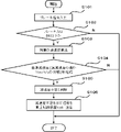
- FIG. 3 is a diagram for explaining the first operation of the central device 101 of the train control system 1 according to the first embodiment.
- the central device 101 receives a brake command from the on-board control device 100 (S101).
- S102 it is determined whether or not a braking command with a braking force equal to or greater than the braking force B6 has been input (S102). If the input braking command is not a braking command with a braking force B6 or more (S102: N), the process is terminated. If the input brake command is a brake command with a braking force of B6 or more (S102: Y), the deceleration is calculated from the speed of the train 10 (S103).
- the calculated deceleration is expressed as actual deceleration. Compares the reference deceleration stored in advance with the actual deceleration stored in the storage unit, and determines whether or not the state in which the difference between the reference deceleration and the actual deceleration is equal to or greater than a predetermined threshold continues for a certain period of time. (S104).
- the predetermined threshold here is, for example, 1 km/h/s, but the threshold may be set as appropriate.
- the fixed time here is, for example, two seconds, but the time may be set as appropriate.
- the comparison between the reference deceleration and the actual deceleration may be the ratio between the reference deceleration and the actual deceleration instead of the difference.
- FIG. 4 is a diagram for explaining the first operation of the on-board control device 100 of the train control system 1 according to the first embodiment.
- the on-board control device 100 receives a signal indicating insufficient deceleration from the central device 101 (S111). Next, the on-board control device 100 generates an emergency braking command, transmits it to the central device 101 (S112), and terminates the process.
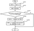
- FIG. 5 is a diagram explaining the second operation of the central device 101 of the train control system 1 according to the first embodiment.
- the central device 101 receives an emergency braking command from the on-board control device 100 (S201).
- a deceleration is calculated from the speed of the train 10 (S202).
- the calculated deceleration is expressed as actual deceleration.
- the emergency brake reference deceleration is the deceleration obtained when an emergency brake command is input under normal conditions.
- the predetermined threshold here is, for example, 1 km/h/s, but the threshold may be set as appropriate.
- the fixed time here is, for example, two seconds, but the time may be set as appropriate. If the difference between the emergency brake reference deceleration and the actual deceleration does not remain equal to or greater than the predetermined threshold for a certain period of time (S203: N), it is determined that sufficient deceleration has been obtained, and the process ends. . If the difference between the emergency brake reference deceleration and the actual deceleration remains equal to or greater than a predetermined threshold for a certain period of time (S203: Y), it is determined that sufficient deceleration is not obtained, that is, insufficient deceleration. (S204).
- the central unit 101 determines that the deceleration is insufficient, the central unit 101 transmits a signal indicating the emergency brake deceleration shortage to the on-board control unit 100 (S205), and ends the process.
- the comparison between the emergency brake reference deceleration and the actual deceleration may be the ratio between the emergency brake reference deceleration and the actual deceleration instead of the difference.
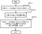
- FIG. 6 is a diagram for explaining the second operation of the on-board control device 100 of the train control system 1 according to the first embodiment.
- the on-board control device 100 receives a signal indicating insufficient emergency braking deceleration from the central device 101 (S211). Next, based on the train position and the actual deceleration of the train 10, a predicted position where the train 10 will stop is calculated (S212). A signal indicating insufficient emergency braking deceleration and a stop position signal indicating the predicted train stop position are generated and transmitted to the ground control device 60 via the on-board radio station 102 (S213), and the process ends.
- FIG. 7 is a diagram explaining the second operation of the ground control device 60 of the train control system 1 according to the first embodiment.
- the ground control device 60 transmits a signal indicating insufficient emergency braking deceleration of the train 10 and a stop position signal indicating the predicted train stop position of the train 10 transmitted from the on-board control device 100 of the train 10 via a radio base station. (S221).
- the ground control device 60 transmits a signal indicating insufficient emergency braking deceleration of the train 10 and a stop signal indicating the predicted train stop position of the train 10 to the train 20, which is the preceding train of the train 10, via the radio base station.
- a position signal is transmitted (S222), and the process ends.
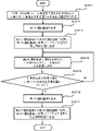
- FIG. 8 is a diagram for explaining the operation of the on-board control device 200 of the train control system 1 according to the first embodiment.
- the on-board control device 200 receives from the ground control device 60 a signal indicating insufficient emergency brake deceleration of the train 10 and a stop position signal indicating the predicted train stop position of the train 10 (S311).
- a second running curve is generated (S312), the set running curve is changed from the first running curve to the second running curve, and a signal indicating the change to the second running curve is sent to the ground. It is transmitted to the control device 60 (S313).
- a powering command and a braking command for controlling the train along the second run curve are sent to the central unit of the train 20 (S314).
- the train position of the tail end of the train 20 is compared with the predicted train stop position of the train 10 received from the ground control device 60, and whether the train position of the tail end of the train 20 is forward with respect to the direction of travel of the train. It is determined whether or not (S315).
- the train control is continued along the second running curve.
- a third running curve is generated (S316). The set running curve is changed from the second running curve to the third running curve, a signal indicating the change to the third running curve is transmitted to the ground control device 60 (S317), and the process is terminated.
- the first running curve is the running curve set before receiving the signal regarding the train 10 from the ground control device 60 .
- Train 20 is controlling the train along the first run curve before receiving a signal regarding train 10 from ground control device 60 .
- a second running curve is a running curve set after receiving a signal regarding the train 10 from the ground control device 60 .
- train 20 controls the train along a second run curve.
- the second running curve is a running curve set so as to widen the interval between trains 10 .
- it is a running curve that reflects control for increasing the speed of the train after receiving a signal regarding the train 10 from the ground control device 60, control for canceling the deceleration state if the train is decelerating, and the like.
- a third running curve is a running curve set when it is determined that the position of the train tail end of the train 20 has passed the predicted stop position of the train 10, and is the current train position of the train 20 and the ground control device. This is a newly generated running curve based on the stop limit information transmitted from 60.
- FIG. 1 A third running curve is a running curve set when it is determined that the position of the train tail end of the train 20 has passed the predicted stop position of the train 10, and is the current train position of the train 20 and the ground control device. This is a newly generated running curve based on the stop limit information transmitted from 60.
- the train 20 can notify that the running in the emergency evacuation mode has been canceled by notifying the ground control device 60 of the change from the second running curve to the third running curve.
- the train at the end of the train is calculated based on the train position calculated by the on-board control device 200 and the pre-stored train length.
- FIG. 9 is a diagram explaining the third operation of the ground control device 60 of the train control system 1 according to the first embodiment.
- the ground control device 60 receives from the on-board control device 200 of the train 20 a signal indicating that the running curve of the train 20 has been changed from the first running curve to the second running curve (S321).
- a signal indicating that the train 20 is running in the emergency evacuation mode is transmitted to the on-board controller 300 of the train 30 (S322).
- a signal indicating that the running curve of the train 20 has been changed from the second running curve to the third running curve is received from the on-board controller 200 of the train 20 (S323).
- a signal indicating that the emergency evacuation mode running of the train 20 has been canceled is transmitted to the on-board control device 300 of the train 30 (S324), and the process ends.
- the first on-board device mounted on the first train runs in the same traveling direction as the first train, and runs ahead of the first train.
- a second on-board device mounted on a second train the on-track position of the first train calculated by the first on-board device, and the on-track location of the second train calculated by the second on-board device and a ground control device for controlling the first train and the second train based on the position, the first on-board device predetermines the actual deceleration of the first train. If it is determined that the deceleration is insufficient compared to the reference deceleration set, an emergency brake command is generated, the emergency brake device mounted on the first train is controlled, and the actual deceleration of the first train is set in advance.
- the first stop position of the first train is predicted based on the first signal indicating insufficient deceleration and the actual deceleration.
- a first stop position signal indicating the predicted first stop position is transmitted to the ground control device, and the ground control device receives the first signal and the first stop position signal from the first on-board device.
- the second running curve is such that the train interval between the second train and the first train is wider than when the second train is controlled on the first running curve.
- a train running in the vicinity can be safely controlled by using a running curve that is controlled to be smooth.
- the first on-board device detects that the difference between the emergency brake reference deceleration and the actual deceleration is equal to or greater than a predetermined threshold value and continues for a predetermined time. Furthermore, by judging that the deceleration is insufficient, it is possible to carry out safe running control of the train running nearby.
- FIG. 10 is a diagram for explaining the operation of the onboard control device 200 of the train control system 1 according to the second embodiment.
- the on-board control device 200 receives from the ground control device 60 a signal indicating insufficient emergency braking deceleration of the train 10 and a stop position signal indicating the predicted train stop position of the train 10 (S411).
- a second running curve is generated (S412), the set running curve is changed from the first running curve to the second running curve, and a signal indicating the change to the second running curve is sent to the ground. It is transmitted to the control device 60 (S413).
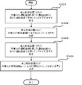
- the predicted train stop position of the train 20 is calculated (S414).
- the predicted train stop position of the train 20 is compared with the stop limit position transmitted from the ground control device 60, and it is determined whether or not the predicted train stop position of the train 20 is ahead of the stop limit position with respect to the traveling direction of the train. It judges (S415). When it is determined that the predicted train stop position of the train 20 is ahead of the stop limit position (S415: Y), a signal indicating that the stop limit position is exceeded is transmitted to the ground control device 60 (S416). When it is determined that the predicted train stop position of the train 20 is not ahead of the stop limit position (S415: N), the process proceeds to S417.
- the train position of the tail end of the train 20 is compared with the predicted train stop position of the train 10 received from the ground control device 60, and whether the train position of the tail end of the train 20 is forward with respect to the direction of travel of the train. It is determined whether or not (S417).
- the train control is continued along the second running curve.
- a third running curve is generated (S418).
- the set running curve is changed from the second running curve to the third running curve, a signal indicating that the running curve has been changed to the third running curve is transmitted to the ground control device 60 (S419), and the process ends.
- FIG. 11 is a diagram for explaining the operation of the ground control device 60 of the train control system 1 according to the second embodiment.
- the ground control device 60 receives from the on-board control device 200 of the train 20 a signal indicating that the running curve of the train 20 has been changed from the first running curve to the second running curve and a signal indicating that the stop limit position has been exceeded. (S421).
- a signal indicating that the train 20 is running in the emergency evacuation mode and a signal requesting a change to the operation curve for emergency evacuation of the train 30 are transmitted to the on-board controller 300 of the train 30 (S422).
- a signal indicating that the running curve of the train 20 has been changed from the second running curve to the third running curve is received from the on-board controller 200 of the train 20 (S423).
- a signal indicating that the emergency evacuation mode running of the train 20 has been canceled and a signal requesting cancellation of the emergency evacuation running curve are transmitted to the on-board control device 300 of the train 30 (S424), and the process ends. do.
- FIG. 12 is a diagram for explaining the operation of the on-board control device 300 of the train 30 of the train control system 1 according to the second embodiment.
- the on-board control device 300 receives from the ground control device 60 a signal indicating that the train 20 is running in emergency evacuation mode and a signal requesting that the train 30 change to an emergency evacuation operation curve (S431).
- the operation curve of the train 30 is changed to the operation curve for emergency evacuation, and the train 30 is controlled (S432).
- a signal indicating that the emergency evacuation mode running of the train 20 has been canceled and a signal requesting cancellation of the emergency evacuation run curve are received from the ground control device 60 (S433).
- the operation curve of the train 30 is changed from the emergency evacuation operation curve to the normal operation curve, and the train 30 is controlled (S434).
- the emergency evacuation running curve is a running curve corresponding to the second running curve described in the second embodiment.
- the normal running curve changed from the emergency evacuation running curve is a running curve corresponding to the third running curve described in the third embodiment.
- the second on-board device predicts the second stop position of the second train, compares the predicted second stop position with the stop limit position of the second train, and determines that the second stop position is a signal indicating that the second train exceeds the stop limit position of the second train when the second train is positioned ahead of the stop limit position of the second train in the traveling direction of the second train; By transmitting a signal indicating the change from the curve to the second operation curve to the ground control device, it is possible to perform safe running control of trains running nearby.
- the second on-board device When detecting that the tail position of the second train has passed the first stop position, the second on-board device cancels the second run curve, generates a third run curve, and By controlling this train, it is possible to perform safe running control of trains running nearby.
- a third on-board device mounted on a third train running in the same direction as the first train and the second train and running ahead of the second train;
- the device receives from the second on-board device a signal indicating that the second train exceeds the stop limit position of the second train and a signal indicating that the first running curve has changed to the second running curve. is received, a signal indicating that the second train is running in the emergency evacuation mode is sent to the third on-board device, and the operation curve of the third train is changed to the operation curve for emergency evacuation.
- the third on-board device receives a signal from the ground control device indicating that the second train is running in emergency evacuation mode, and changes the running curve of the third train to the running curve for emergency evacuation.
- a signal requesting and, by changing the operation curve of the third train to the operation curve for emergency evacuation and controlling the third train, safe running control of the train running nearby It can be performed.
- the ground control device 60 and the on-board control device 100 comprise at least a processor, a memory, a receiver, and a transmitter, and the operation of each device can be realized by software.
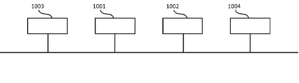
- FIG. 13 is a diagram showing a general configuration example of hardware that implements the ground control device 60 and the on-board control device of the train control system 1 according to the first embodiment.
- the apparatus shown in FIG. 13 comprises a processor 1001, a memory 1002, a receiver 1003 and a transmitter 1004.
- the processor 1001 uses received data to perform computation and control by software.
- the memory 1002 stores the received data or data required when the processor 1001 performs calculations and controls, and also stores software.
- the receiver 1003 is an interface that receives signals or information input to the ground control device 60 or the on-board control device.
- the transmitter 1004 is an interface that transmits signals or information output from the ground control device 60 or the on-board control device. Multiple processors 1001, memories 1002, receivers 1003, and transmitters 1004 may be provided.
Landscapes
- Engineering & Computer Science (AREA)
- Mechanical Engineering (AREA)
- Power Engineering (AREA)
- Transportation (AREA)
- Electric Propulsion And Braking For Vehicles (AREA)
- Train Traffic Observation, Control, And Security (AREA)
Priority Applications (4)
| Application Number | Priority Date | Filing Date | Title |
|---|---|---|---|
| PCT/JP2021/013960 WO2022208781A1 (ja) | 2021-03-31 | 2021-03-31 | 列車制御システム |
| DE112021007467.9T DE112021007467T5 (de) | 2021-03-31 | 2021-03-31 | Zugsteuersystem |
| US18/551,627 US12528526B2 (en) | 2021-03-31 | 2021-03-31 | Train control system |
| JP2023510066A JP7325683B2 (ja) | 2021-03-31 | 2021-03-31 | 列車制御システム |
Applications Claiming Priority (1)
| Application Number | Priority Date | Filing Date | Title |
|---|---|---|---|
| PCT/JP2021/013960 WO2022208781A1 (ja) | 2021-03-31 | 2021-03-31 | 列車制御システム |
Publications (1)
| Publication Number | Publication Date |
|---|---|
| WO2022208781A1 true WO2022208781A1 (ja) | 2022-10-06 |
Family
ID=83458229
Family Applications (1)
| Application Number | Title | Priority Date | Filing Date |
|---|---|---|---|
| PCT/JP2021/013960 Ceased WO2022208781A1 (ja) | 2021-03-31 | 2021-03-31 | 列車制御システム |
Country Status (4)
| Country | Link |
|---|---|
| US (1) | US12528526B2 (https=) |
| JP (1) | JP7325683B2 (https=) |
| DE (1) | DE112021007467T5 (https=) |
| WO (1) | WO2022208781A1 (https=) |
Cited By (1)
| Publication number | Priority date | Publication date | Assignee | Title |
|---|---|---|---|---|
| US20240174275A1 (en) * | 2021-03-31 | 2024-05-30 | Mitsubishi Electric Corporation | Train control system |
Families Citing this family (1)
| Publication number | Priority date | Publication date | Assignee | Title |
|---|---|---|---|---|
| CN116279662B (zh) * | 2023-03-22 | 2025-08-08 | 中车株洲电力机车有限公司 | 一种磁浮列车停车系统及方法 |
Citations (2)
| Publication number | Priority date | Publication date | Assignee | Title |
|---|---|---|---|---|
| JP2009029234A (ja) * | 2007-07-26 | 2009-02-12 | Light Rail:Kk | 列車運転指示装置 |
| JP2018083495A (ja) * | 2016-11-22 | 2018-05-31 | 株式会社東芝 | 列車運行制御システム |
Family Cites Families (12)
| Publication number | Priority date | Publication date | Assignee | Title |
|---|---|---|---|---|
| FR2856645B1 (fr) | 2003-06-27 | 2005-08-26 | Alstom | Dispositif et procede de commande de trains, notamment du type ertms |
| JP5904740B2 (ja) | 2011-09-30 | 2016-04-20 | 日本信号株式会社 | 列車制御システム |
| JP6466116B2 (ja) * | 2014-09-12 | 2019-02-06 | 株式会社東芝 | 運行制御システム |
| US9758183B2 (en) * | 2014-09-30 | 2017-09-12 | Apple Inc. | Location fingerprinting for transit systems |
| US10757671B2 (en) * | 2014-09-30 | 2020-08-25 | Apple Inc. | Location fingerprinting for a transit system |
| US9392415B2 (en) * | 2014-09-30 | 2016-07-12 | Apple Inc. | Modeling connectivity of transit systems |
| DE102015210550A1 (de) * | 2015-06-09 | 2016-12-15 | Siemens Aktiengesellschaft | Verfahren und Anordnung zum Sicherstellen eines Flankenschutzes für Züge |
| WO2018088366A1 (ja) * | 2016-11-10 | 2018-05-17 | 三菱電機株式会社 | 自動列車運転装置 |
| JP6889059B2 (ja) * | 2017-07-19 | 2021-06-18 | 株式会社東芝 | 情報処理装置、情報処理方法及びコンピュータプログラム |
| US11001284B2 (en) * | 2018-11-30 | 2021-05-11 | Westinghouse Air Brake Technologies Corporation | Method for determining location of other trains for PTC purposes |
| US12012135B2 (en) * | 2018-11-30 | 2024-06-18 | Westinghouse Air Brake Technologies Corporation | Vehicle warning system |
| US12528526B2 (en) * | 2021-03-31 | 2026-01-20 | Mitsubishi Electric Corporation | Train control system |
-
2021
- 2021-03-31 US US18/551,627 patent/US12528526B2/en active Active
- 2021-03-31 WO PCT/JP2021/013960 patent/WO2022208781A1/ja not_active Ceased
- 2021-03-31 JP JP2023510066A patent/JP7325683B2/ja active Active
- 2021-03-31 DE DE112021007467.9T patent/DE112021007467T5/de active Pending
Patent Citations (2)
| Publication number | Priority date | Publication date | Assignee | Title |
|---|---|---|---|---|
| JP2009029234A (ja) * | 2007-07-26 | 2009-02-12 | Light Rail:Kk | 列車運転指示装置 |
| JP2018083495A (ja) * | 2016-11-22 | 2018-05-31 | 株式会社東芝 | 列車運行制御システム |
Cited By (2)
| Publication number | Priority date | Publication date | Assignee | Title |
|---|---|---|---|---|
| US20240174275A1 (en) * | 2021-03-31 | 2024-05-30 | Mitsubishi Electric Corporation | Train control system |
| US12528526B2 (en) * | 2021-03-31 | 2026-01-20 | Mitsubishi Electric Corporation | Train control system |
Also Published As
| Publication number | Publication date |
|---|---|
| DE112021007467T5 (de) | 2024-02-15 |
| JP7325683B2 (ja) | 2023-08-14 |
| US12528526B2 (en) | 2026-01-20 |
| US20240174275A1 (en) | 2024-05-30 |
| JPWO2022208781A1 (https=) | 2022-10-06 |
Similar Documents
| Publication | Publication Date | Title |
|---|---|---|
| CN110758484B (zh) | 列车自动驾驶方法、vobc、tias、区域控制器 | |
| KR102173984B1 (ko) | 자율주행 차량의 브레이크 제어 장치 | |
| JP4880011B2 (ja) | 車両用追従走行制御装置 | |
| JP4920431B2 (ja) | 衝突被害軽減システム | |
| JP5293699B2 (ja) | 車両制御装置 | |
| KR102013156B1 (ko) | 전기차의 자율주행을 위한 차량 제어 방법 및 그를 위한 장치 | |
| CN110758485A (zh) | 列车自动驾驶的方法、车载控制器、tias、设备和介质 | |
| JP7325683B2 (ja) | 列車制御システム | |
| EP3104355B1 (en) | Work vehicle control system | |
| CN109878557B (zh) | 一种全自动运行系统中蠕动驾驶模式实现方法及系统 | |
| CN102325684A (zh) | 无线列车控制系统、无线列车控制车上系统及无线列车控制地上系统 | |
| CN112193248A (zh) | 用于列队行驶系统的后备保护系统 | |
| JP2009232574A (ja) | 列車制御装置 | |
| KR102446142B1 (ko) | 자율주행 차량의 브레이크 제어 장치 | |
| MX2023009982A (es) | Sistema y metodo para evitar que un vehiculo ruede. | |
| WO2015019431A1 (ja) | 列車制御システム及びこれを備えた列車 | |
| KR102456794B1 (ko) | 자율주행 차량의 브레이크 제어 장치 | |
| JPWO2022208781A5 (https=) | ||
| JP6498633B2 (ja) | 車両操作支援装置 | |
| JP4713755B2 (ja) | 列車制御システム | |
| CN113022561B (zh) | 车辆控制方法及装置 | |
| JP2019140810A (ja) | 軌道輸送システム | |
| JP2011010515A (ja) | 電気車の無線保安用制御装置 | |
| JP2011168217A (ja) | 運行支援システム及び運行支援方法 | |
| JP2019026066A (ja) | 軌道輸送システム、軌道輸送システムの運行方法 |
Legal Events
| Date | Code | Title | Description |
|---|---|---|---|
| 121 | Ep: the epo has been informed by wipo that ep was designated in this application |
Ref document number: 21934947 Country of ref document: EP Kind code of ref document: A1 |
|
| ENP | Entry into the national phase |
Ref document number: 2023510066 Country of ref document: JP Kind code of ref document: A |
|
| WWE | Wipo information: entry into national phase |
Ref document number: 18551627 Country of ref document: US |
|
| WWE | Wipo information: entry into national phase |
Ref document number: 202327063880 Country of ref document: IN |
|
| WWE | Wipo information: entry into national phase |
Ref document number: 112021007467 Country of ref document: DE |
|
| 122 | Ep: pct application non-entry in european phase |
Ref document number: 21934947 Country of ref document: EP Kind code of ref document: A1 |
|
| WWG | Wipo information: grant in national office |
Ref document number: 18551627 Country of ref document: US |