WO2022208727A1 - 冷凍サイクル装置 - Google Patents
冷凍サイクル装置 Download PDFInfo
- Publication number
- WO2022208727A1 WO2022208727A1 PCT/JP2021/013849 JP2021013849W WO2022208727A1 WO 2022208727 A1 WO2022208727 A1 WO 2022208727A1 JP 2021013849 W JP2021013849 W JP 2021013849W WO 2022208727 A1 WO2022208727 A1 WO 2022208727A1
- Authority
- WO
- WIPO (PCT)
- Prior art keywords
- refrigerant
- branch
- heat exchanger
- refrigeration cycle
- flow path
- Prior art date
- Legal status (The legal status is an assumption and is not a legal conclusion. Google has not performed a legal analysis and makes no representation as to the accuracy of the status listed.)
- Ceased
Links
Images


Classifications
-
- F—MECHANICAL ENGINEERING; LIGHTING; HEATING; WEAPONS; BLASTING
- F25—REFRIGERATION OR COOLING; COMBINED HEATING AND REFRIGERATION SYSTEMS; HEAT PUMP SYSTEMS; MANUFACTURE OR STORAGE OF ICE; LIQUEFACTION SOLIDIFICATION OF GASES
- F25B—REFRIGERATION MACHINES, PLANTS OR SYSTEMS; COMBINED HEATING AND REFRIGERATION SYSTEMS; HEAT PUMP SYSTEMS
- F25B1/00—Compression machines, plants or systems with non-reversible cycle
- F25B1/10—Compression machines, plants or systems with non-reversible cycle with multi-stage compression
-
- F—MECHANICAL ENGINEERING; LIGHTING; HEATING; WEAPONS; BLASTING
- F25—REFRIGERATION OR COOLING; COMBINED HEATING AND REFRIGERATION SYSTEMS; HEAT PUMP SYSTEMS; MANUFACTURE OR STORAGE OF ICE; LIQUEFACTION SOLIDIFICATION OF GASES
- F25B—REFRIGERATION MACHINES, PLANTS OR SYSTEMS; COMBINED HEATING AND REFRIGERATION SYSTEMS; HEAT PUMP SYSTEMS
- F25B13/00—Compression machines, plants or systems, with reversible cycle
-
- F—MECHANICAL ENGINEERING; LIGHTING; HEATING; WEAPONS; BLASTING
- F25—REFRIGERATION OR COOLING; COMBINED HEATING AND REFRIGERATION SYSTEMS; HEAT PUMP SYSTEMS; MANUFACTURE OR STORAGE OF ICE; LIQUEFACTION SOLIDIFICATION OF GASES
- F25B—REFRIGERATION MACHINES, PLANTS OR SYSTEMS; COMBINED HEATING AND REFRIGERATION SYSTEMS; HEAT PUMP SYSTEMS
- F25B40/00—Subcoolers, desuperheaters or superheaters
-
- F—MECHANICAL ENGINEERING; LIGHTING; HEATING; WEAPONS; BLASTING
- F25—REFRIGERATION OR COOLING; COMBINED HEATING AND REFRIGERATION SYSTEMS; HEAT PUMP SYSTEMS; MANUFACTURE OR STORAGE OF ICE; LIQUEFACTION SOLIDIFICATION OF GASES
- F25B—REFRIGERATION MACHINES, PLANTS OR SYSTEMS; COMBINED HEATING AND REFRIGERATION SYSTEMS; HEAT PUMP SYSTEMS
- F25B41/00—Fluid-circulation arrangements
- F25B41/40—Fluid line arrangements
-
- F—MECHANICAL ENGINEERING; LIGHTING; HEATING; WEAPONS; BLASTING
- F25—REFRIGERATION OR COOLING; COMBINED HEATING AND REFRIGERATION SYSTEMS; HEAT PUMP SYSTEMS; MANUFACTURE OR STORAGE OF ICE; LIQUEFACTION SOLIDIFICATION OF GASES
- F25B—REFRIGERATION MACHINES, PLANTS OR SYSTEMS; COMBINED HEATING AND REFRIGERATION SYSTEMS; HEAT PUMP SYSTEMS
- F25B2400/00—Component parts or details not otherwise provided for in this subclass
- F25B2400/13—Economisers
-
- F—MECHANICAL ENGINEERING; LIGHTING; HEATING; WEAPONS; BLASTING
- F25—REFRIGERATION OR COOLING; COMBINED HEATING AND REFRIGERATION SYSTEMS; HEAT PUMP SYSTEMS; MANUFACTURE OR STORAGE OF ICE; LIQUEFACTION SOLIDIFICATION OF GASES
- F25B—REFRIGERATION MACHINES, PLANTS OR SYSTEMS; COMBINED HEATING AND REFRIGERATION SYSTEMS; HEAT PUMP SYSTEMS
- F25B2400/00—Component parts or details not otherwise provided for in this subclass
- F25B2400/23—Separators
Definitions
- the present disclosure relates to a refrigeration cycle device.
- a conventional refrigeration cycle device has a heat exchanger, and the heat exchanger functions, for example, as a condenser mounted on the indoor unit.
- the liquid refrigerant condensed in the heat exchanger is depressurized by the expansion device, and becomes a gas-liquid two-phase state in which gas refrigerant and liquid refrigerant are mixed.
- the gas-liquid two-phase refrigerant is turned into a low-pressure gas refrigerant by evaporating the liquid refrigerant of the gas-liquid two-phase refrigerant in a heat exchanger that functions as an evaporator mounted in the outdoor unit.
- the low-pressure gas refrigerant sent out from the heat exchanger flows into the compressor, is compressed by the compressor, becomes high-temperature and high-pressure gas refrigerant, and is discharged from the compressor again. This cycle is repeated in the refrigeration cycle device.
- the gas-liquid two-phase refrigerant or liquid-phase refrigerant flowing through the bypass circuit joins the main stream flowing through the main circuit. Therefore, in the configuration of Patent Document 1, if the flow rate of the refrigerant flowing through the bypass circuit is increased in order to reduce the pressure loss in the main circuit, an excessive amount of liquid-phase refrigerant is supplied to the compressor, causing heat loss and causing heat loss in the compressor. As the amount of liquid refrigerant to be supplied increases, the performance of the compressor deteriorates and the energy saving performance deteriorates.
- the present disclosure is intended to solve the problems described above, and aims to provide a refrigeration cycle device that achieves both compressor performance and securing of space required for installing equipment.
- a refrigeration cycle apparatus includes a main circuit that is pipe-connected so that a refrigerant flows, and a bypass circuit that is pipe-connected so that the refrigerant flows and branches from the main circuit and joins the main circuit.
- a fourth branch provided in the refrigerant flow path from the third branch to the discharge port of the compressor and forming at least three branches
- the bypass circuit includes the first branch to the third branch and the A second throttle that configures the refrigerant flow path up to the fourth branch, is provided in the refrigerant flow path between the first branch and the low-temperature side flow path of the first refrigerant heat exchanger, and decompresses the refrigerant.
- a device a first heat exchanger between refrigerants having a low temperature side channel as part of a bypass circuit, and a refrigerant channel provided between the low temperature side channel and the third branch portion and the fourth branch portion, a second branching portion for branching the refrigerant flowing out of the low-temperature side flow path of the heat exchanger between refrigerants into two, the second branching portion having a liquid outflow pipe and a gas outflow pipe; , the liquid outflow pipe forms an outlet for the refrigerant located below the gas outflow pipe, the gas outflow pipe forms another outlet for the refrigerant and is arranged above the liquid outflow pipe; One outlet of the two branches communicates with the third branch, and the other outlet of the second branch communicates with the fourth branch.
- the refrigeration cycle device includes a liquid outflow pipe that forms a refrigerant outlet located below the gas outflow pipe and a gas outflow pipe that forms another refrigerant outlet and is provided above the liquid outflow pipe. and a second branching portion for branching the refrigerant into two.
- the second branch part has a gas outflow pipe and a liquid outflow pipe that are arranged vertically in the direction of gravity, so that the gas-dominant refrigerant in the gas-liquid two-phase state is transferred to the gas outflow pipe rather than the gas-dominant refrigerant.
- the liquid-based refrigerant with low dryness is separated into the liquid outlet pipe.
- the refrigeration cycle device supplies the separated refrigerants to the main circuit from the evaporator to the compressor discharge port, thereby reducing the refrigerant flow rate in the bypass circuit without excessively supplying liquid refrigerant to the compressor suction port. can be increased. Therefore, the refrigeration cycle apparatus can improve the performance of the compressor without increasing the size of the equipment, and can ensure both the performance of the compressor and the space required for installing the equipment.
- FIG. 1 is a refrigerant circuit diagram showing a first example of a refrigeration cycle apparatus according to Embodiment 1.
- FIG. FIG. 2 is a refrigerant circuit diagram in which part of the refrigerant flow path of the refrigeration cycle device according to Embodiment 1 is omitted; 2 is a perspective view showing an example of a first heat exchanger between refrigerants mounted in the refrigeration cycle apparatus according to Embodiment 1.
- FIG. 4 is a perspective view of a second branch connected to the first heat exchanger between refrigerants shown in FIG. 3.
- FIG. FIG. 5 is a schematic diagram of an example of the second branching portion of FIG. 4 viewed from the flow path cross-sectional side of the inflow pipe;
- FIG. 5 is a cross-sectional view schematically showing a cross-section of the second branching portion for explaining the flow of refrigerant in the second branching portion.
- It is a schematic diagram which shows the 1st modification of a 2nd branch part.
- It is a schematic diagram which shows the 2nd modification of a 2nd branch part.
- It is a schematic diagram which shows the 3rd modification of a 2nd branch part.
- It is a schematic diagram which shows the 4th modification of a 2nd branch part.
- It is a schematic diagram which shows the 5th modification of a 2nd branch part.
- It is the graph which compared notionally the energy-saving performance ratio with respect to the bypass flow rate ratio of a refrigeration cycle apparatus.
- FIG. 4 is a refrigerant circuit diagram showing a first modification of the refrigeration cycle apparatus according to Embodiment 1;
- FIG. 5 is a refrigerant circuit diagram showing a second modification of the refrigeration cycle apparatus according to Embodiment 1;
- FIG. 6 is a schematic diagram showing a refrigeration cycle apparatus according to Embodiment 2; It is a modification of the refrigeration cycle apparatus according to Embodiment 2.
- FIG. 7 is a schematic diagram showing a refrigeration cycle apparatus according to Embodiment 3;
- FIG. 5 is a cross-sectional view schematically showing a cross-section of the second branching portion for explaining the flow of refrigerant in the second branching portion.
- FIG. 11 is a schematic diagram showing a first modification of the refrigeration cycle apparatus according to Embodiment 3;
- FIG. 11 is a schematic diagram showing a second modification of the refrigeration cycle apparatus according to Embodiment 3;
- FIG. 11 is a first schematic diagram showing a refrigeration cycle apparatus according to Embodiment 4;
- FIG. 11 is a second schematic diagram showing a refrigeration cycle apparatus according to Embodiment 4;
- FIG. 11 is a schematic diagram showing a first modification of the refrigeration cycle apparatus according to Embodiment 4;
- FIG. 12 is a schematic diagram showing a second modification of the refrigeration cycle apparatus according to Embodiment 4;
- FIG. 1 is a refrigerant circuit diagram showing a first example of a refrigeration cycle device 200 according to Embodiment 1.
- FIG. FIG. 2 is a refrigerant circuit diagram in which part of the refrigerant flow path 20 of the refrigeration cycle device 200 according to Embodiment 1 is omitted.
- the flow of refrigerant during cooling operation is indicated by solid arrows
- the flow of refrigerant during heating operation is indicated by dashed arrows.
- the refrigerant flow path 20 during the heating operation in FIG. 1 is omitted, and only the refrigerant flow path 20 during the cooling operation is shown for ease of viewing.
- the refrigeration cycle device 200 is used for refrigeration or air conditioning, such as refrigerators, freezers, vending machines, air conditioners, refrigeration systems, and water heaters.
- the refrigeration cycle device 200 includes an outdoor unit 201 and an indoor unit 202.
- the outdoor unit 201 includes a compressor 14, a flow path switching device 15, an outdoor heat exchanger 11, a first heat exchanger between refrigerants 1, a first expansion device 21, a second expansion device 22, and an outdoor fan 13.
- the indoor unit 202 includes an indoor heat exchanger 16 and an indoor fan 18 .
- the refrigeration cycle device 200 may have a control device 210 that controls the operating state of the refrigeration cycle device 200, such as cooling operation or heating operation.
- the refrigeration cycle device 200 also has a refrigerant flow path 20 formed by connecting the above-described devices such as the compressor 14 .
- a refrigerant flow path 20 made of refrigerant piping forms a flow path through which a refrigerant flows.
- the refrigerant channel 20 is formed by connecting the outdoor unit 201 and the indoor unit 202 with a pipe so that the refrigerant can move between the outdoor unit 201 and the indoor unit 202 .
- the refrigerant flow path 20 is connected to a main circuit 20a that is annularly connected so that the refrigerant flows, and the refrigerant that flows through the main circuit 20a branches from the main circuit 20a and returns to the main circuit 20a. and a bypass circuit 20b forming a converging flow.
- the main circuit 20a includes the compressor 14, the outdoor heat exchanger 11 which is the first condenser, the high temperature side flow path 1a of the first heat exchanger between refrigerants 1, the first expansion device 21, and the first It has an indoor heat exchanger 16 which is an evaporator, and each of these devices is connected by piping so that the refrigerant flows.
- the main circuit 20a also has a first branch portion 31 forming at least three branches, a third branch portion 33 forming at least three branches, and a fourth branch portion 34 forming at least three branches.
- the main circuit 20a may have a channel switching device 15 between the compressor 14 and the outdoor heat exchanger 11, as shown in FIG.
- the bypass circuit 20b branches at a first branch portion 31 provided in the refrigerant flow path 20 from the first heat exchanger between refrigerants 1 to the first expansion device 21 of the main circuit 20a.
- the bypass circuit 20 b constitutes the refrigerant flow path 20 from the first branch portion 31 to the third branch portion 33 and the fourth branch portion 34 .
- the bypass circuit 20b includes a first branch portion 31, a second expansion device 22, a low temperature side flow path 1b of the first heat exchanger between refrigerants 1, a second branch portion 32, a third expansion device 23, a fourth expansion device 24, Further, pipe connection is made so that the refrigerant flows to the third branch portion 33 and the fourth branch portion 34, which are the connection portions with the main circuit 20a.
- the bypass circuit 20b has a first branch path 20b1 and a second branch path 20b2 branched by the second branch portion 32.
- the first branched passage 20b1 is a flow passage that connects the liquid outlet pipe 4 of the second branched portion 32 and the third branched portion 33 .
- a third throttle device 23 is provided in the first branch passage 20b1.
- the second branched passage 20b2 is a flow passage that connects the gas outlet pipe 5 of the second branched portion 32 and the fourth branched portion .
- a fourth expansion device 24 is provided in the second branch passage 20b2.
- the liquid outflow pipe 4 is connected to the third branch portion 33 and the gas outflow pipe 5 is connected to the fourth branch portion 34 .
- the refrigeration cycle apparatus 200 includes the check valve 42 and the flow path switching device so that the flow direction of the first heat exchanger 1 between refrigerants does not change even when the cooling operation and the heating operation are switched. 15.
- the check valve 42 connects the main circuit 20a between the first expansion device 21 and the indoor heat exchanger 16 and the main circuit 20a between the outdoor heat exchanger 11 and the first heat exchanger 1 between refrigerants. provided in the coolant channel 20 .
- the check valve 42 is a device that allows the refrigerant to flow in one direction.
- the refrigeration cycle apparatus 200 according to Embodiment 1 has this configuration, the high-temperature side flow path 1a and the low-temperature side flow path 1b of the first heat exchanger between refrigerants 1 are countercurrent, so that the first refrigerant It is possible to achieve heat exchange between refrigerants without increasing the size of the intermediate heat exchanger 1 .
- the compressor 14 sucks in the refrigerant, compresses the refrigerant, and discharges it in a state of high temperature and high pressure.
- the refrigerant compressed by the compressor 14 is discharged and sent to the flow switching device 15 .
- the compressor 14 is configured by, for example, a rotary compressor, a scroll compressor, a screw compressor, or a reciprocating compressor.
- the channel switching device 15 is, for example, a four-way valve, and switches the direction in which the coolant flows in the coolant channel 20 .
- the flow path switching device 15 switches between the direction in which the refrigerant flows during the heating operation and the direction in which the refrigerant flows during the cooling operation in the refrigeration cycle device 200 .
- the flow switching device 15 connects the discharge port 14b of the compressor 14 and the outdoor heat exchanger 11, and also connects the suction port 14a of the compressor 14 and the indoor heat exchanger 16.
- the flow path switching device 15 connects the discharge port 14b of the compressor 14 and the indoor heat exchanger 16 and connects the suction port 14a of the compressor 14 and the outdoor heat exchanger 11 during cooling operation. switch the refrigerant flow to
- the outdoor heat exchanger 11 functions as an evaporator during heating operation, exchanges heat between the refrigerant that has flowed into the interior and the outdoor air, and evaporates the refrigerant.
- the outdoor heat exchanger 11 functions as a condenser during cooling operation, performs heat exchange between the refrigerant that has flowed inside and the outdoor air, and condenses and liquefies the refrigerant.
- the outdoor heat exchanger 11 is provided with an outdoor fan 13 adjacent to the outdoor heat exchanger 11 in order to increase the efficiency of heat exchange between the refrigerant and the outdoor air.
- the outdoor heat exchanger 11 moves the first condenser in the refrigerant flow direction during the cooling operation indicated by the solid line arrow. Configure.
- the indoor heat exchanger 16 functions as a condenser during heating operation, exchanges heat between the refrigerant that has flowed inside and the indoor air, and condenses and liquefies the refrigerant.
- the indoor heat exchanger 16 functions as an evaporator during cooling operation, performs heat exchange between the refrigerant that has flowed thereinto and indoor air, and evaporates the refrigerant.
- An indoor fan 18 is arranged adjacent to the indoor heat exchanger 16 in order to increase the efficiency of heat exchange between the refrigerant and the outdoor air.
- the indoor heat exchanger 16 moves the first evaporator in the refrigerant flow direction during the cooling operation indicated by the solid line arrow. Configure.
- the outdoor heat exchanger 11 and the indoor heat exchanger 16 function as heat exchangers that transfer heat between the refrigerant flowing through the refrigerant flow path 20 and a heat transport medium such as air flowing outside the tubes.
- the outdoor heat exchanger 11 and the indoor heat exchanger 16 are, for example, a fin-and-tube heat exchanger, a microchannel heat exchanger, a shell-and-tube heat exchanger, a heat pipe heat exchanger, or a double-tube heat exchanger. It consists of a plate heat exchanger, etc.
- the outdoor fan 13 supplies a heat exchange fluid such as air to the outdoor heat exchanger 11, and the indoor fan 18 supplies a heat exchange fluid such as air to the indoor heat exchanger 16.
- the outdoor fan 13 and the indoor fan 18 are composed of a propeller fan, a line flow fan (registered trademark), a multi-blade centrifugal fan, a water pump, or the like, depending on operating conditions such as working fluid and flow rate or static pressure.
- the first heat exchanger between refrigerants 1 forms a high temperature side passage 1a through which a high temperature refrigerant flows, and a low temperature side passage 1b through which a refrigerant having a lower temperature than the refrigerant flowing in the high temperature side passage 1a flows.
- the first heat exchanger between refrigerants 1 exchanges heat between the refrigerant flowing through the high temperature side passage 1a and the refrigerant flowing through the low temperature side passage 1b.
- the high temperature side flow path 1a forms part of the main circuit 20a
- the low temperature side flow path 1b forms part of the bypass circuit 20b.
- the first branch portion 31 is a branch pipe that branches in at least three directions, and is a portion that branches the main circuit 20 a and the bypass circuit 20 b in the refrigerant flow path 20 .
- the first branch portion 31 constitutes a part of the main circuit 20a, and is a portion that diverts the refrigerant flowing through the main circuit 20a to the bypass circuit 20b.
- the first branch portion 31 is provided in the refrigerant flow path 20 from the first heat exchanger between refrigerants 1 to the first expansion device 21 in the main circuit 20a.
- the second branched portion 32 is provided in the refrigerant channel 20 between the low temperature side channel 1b and the third branched portion 33 and the fourth branched portion .
- the second branching portion 32 branches the refrigerant flowing out of the low-temperature side flow path 1b of the first heat exchanger between refrigerants 1 into two.
- the second branch portion 32 is provided so as to be connected to the low temperature side flow path outlet 54 (see FIG. 3) of the first heat exchanger between refrigerants 1 .
- the second branch 32 has a liquid outflow tube 4 and a gas outflow tube 5 .
- the liquid outflow pipe 4 forms a refrigerant outlet located below the gas outflow pipe 5 in the direction of gravity.
- the gas outflow tube 5 forms another outlet for the refrigerant and is arranged above the liquid outflow tube 4 in the direction of gravity.
- One outlet of the second branch 32 communicates with the third branch 33 , and the other outlet of the second branch 32 communicates with the fourth branch 34 .
- a detailed configuration of the second branch portion 32 will be described later.
- the third branch portion 33 is a branch pipe that branches in at least three directions, and is a portion of the refrigerant channel 20 that connects the bypass circuit 20b and the main circuit 20a.
- the third branch portion 33 constitutes a part of the main circuit 20a, and is a portion that joins the refrigerant flowing through the bypass circuit 20b to the main circuit 20a.
- the third branch portion 33 is provided in the main circuit 20a from the indoor heat exchanger 16, which is the first evaporator, to the suction port 14a of the compressor 14, and communicates with one outlet of the second branch portion 32. As shown in FIGS. 1 and 2, between the indoor heat exchanger 16 and the compressor 14 in the direction of refrigerant flow during cooling operation indicated by solid arrows, the third branch 33 is connected to the fourth branch. It is provided so as to be positioned upstream with respect to the portion 34 .
- the third branch portion 33 is a portion that connects the first branch passage 20b1 of the bypass circuit 20b and the main circuit 20a, and connects the first branch passage 20b1 of the bypass circuit 20b. It is a portion that joins the flowing refrigerant to the main circuit 20a.
- fourth branch 34 is arranged between third branch 33 and compressor 14 . Further, in the refrigeration cycle apparatus 200 of Embodiment 1, as shown in FIGS. , and the third branch portion 33 are provided so as to be positioned upstream of the refrigerant tank 6 .
- the fourth branch portion 34 is a branch pipe that branches in at least three directions, and is a portion of the refrigerant flow path 20 that connects the bypass circuit 20b and the main circuit 20a.
- the fourth branch portion 34 constitutes a part of the main circuit 20a, and is a portion that joins the refrigerant flowing through the bypass circuit 20b to the main circuit 20a.
- the fourth branch portion 34 is provided in the main circuit 20 a from the third branch portion 33 to the discharge port 14 b of the compressor 14 and communicates with the other outlet of the second branch portion 32 .
- the fourth branch 34 and the third branch It is provided so as to be positioned on the downstream side with respect to the portion 33 .
- the fourth branch portion 34 is a portion that connects the second branch passage 20b2 of the bypass circuit 20b and the main circuit 20a, and connects the second branch passage 20b2 of the bypass circuit 20b. It is a portion that joins the flowing refrigerant to the main circuit 20a.
- fourth branch 34 is arranged between compressor 14 and third branch 33 . Further, in the refrigeration cycle apparatus 200 of Embodiment 1, as shown in FIGS. , and the fourth branch portion 34 are provided so as to be positioned downstream of the refrigerant tank 6 .
- the first expansion device 21 and the second expansion device 22 function as pressure reducing valves or expansion valves, and expand the refrigerant to reduce the pressure.
- the first expansion device 21 and the second expansion device 22 are composed of, for example, electric expansion valves capable of adjusting the flow rate of the refrigerant. Note that the first expansion device 21 and the second expansion device 22 are not limited to electric expansion valves, and may be configured by mechanical expansion valves employing diaphragms as pressure receiving portions, capillary tubes, or the like.
- the first expansion device 21 is provided in the main circuit 20 a and is provided in the refrigerant flow path 20 between the first branch portion 31 and the indoor heat exchanger 16 .
- the second expansion device 22 is provided in the bypass circuit 20b, and the refrigerant flow path 20 between the first branch portion 31 and the low temperature side flow path inlet 53 (see FIG. 3) of the first heat exchanger between refrigerants 1. is provided in
- the third expansion device 23 and the fourth expansion device 24 function as pressure reducing valves or expansion valves, and expand the refrigerant to reduce the pressure.
- the third expansion device 23 and the fourth expansion device 24 are composed of, for example, electric expansion valves capable of adjusting the flow rate of the refrigerant.
- the third expansion device 23 and the fourth expansion device 24 are not limited to electric expansion valves, and may be configured by mechanical expansion valves employing diaphragms as pressure receiving portions, capillary tubes, or the like.
- the third expansion device 23 is provided in the first branch passage 20b1 of the bypass circuit 20b, and the liquid outflow pipe 4 of the second branch portion 32 and the third branch portion 33 is provided in the coolant channel 20 .
- the fourth expansion device 24 is provided in the second branch passage 20b2 of the bypass circuit 20b, and the gas outflow pipe 5 of the second branch portion 32 and the fourth branch portion 34 in the coolant channel 20 .
- the refrigerant tank 6 is a volumetric tank.
- a capacity-type tank is a tank having an inner diameter larger than that of the refrigerant pipe forming the refrigerant flow path 20 .
- the refrigerant tank 6 separates the gas-liquid two-phase refrigerant flowing into the inside from the outside of the refrigerant tank 6 and discharges the gas-based refrigerant.
- the refrigerant tank 6 has a refrigerant storage function of storing surplus refrigerant and a gas-liquid separation function of storing liquid refrigerant that is temporarily generated when the operating state changes.
- the refrigeration cycle device 200 can prevent the liquid from being compressed in the compressor 14 by the gas-liquid separation function of the refrigerant tank 6 .
- the refrigerant tank 6 is provided between the third branch portion 33 and the fourth branch portion 34 .
- the refrigeration cycle device 200 has a refrigerant tank 6 and can retain liquid refrigerant. That is, the refrigerating cycle device 200 has a structure in which the inner diameter of the tank is larger than that of the refrigerant pipe forming the refrigerant flow path 20, so that the liquid refrigerant can be retained. Therefore, the refrigerant tank 6 can discharge the liquid-based refrigerant flowing into the refrigerant tank 6 as a high-quality refrigerant with less liquid-phase components.
- the refrigeration cycle device 200 can supply the gas-based refrigerant to the compressor 14 and can suppress mixing of the liquid refrigerant into the compressor 14 . Since the refrigerant tank 6 can supply the gas-based refrigerant to the compressor 14 and can suppress the mixture of the liquid refrigerant into the compressor 14, the performance of the refrigeration cycle device 200 can be enhanced.
- the control device 210 controls the operating state of the entire operation of the refrigeration cycle device 200, such as cooling operation or heating operation.
- the control device 210 may control the channel switching device 15 to switch the direction of flow of the coolant in the coolant channel 20 .
- the control device 210 may also control the compressor 14, for example, control the discharge amount of the compressed refrigerant.
- the control device 210 may control the amount of rotation of the outdoor fan 13 and the indoor fan 18 .
- the control device 210 may adjust the opening degrees of the first diaphragm device 21 , the second diaphragm device 22 , the third diaphragm device 23 , and the fourth diaphragm device 24 .
- the control device 210 is composed of, for example, a device that performs control arithmetic processing, such as a computer centered on a CPU (Central Processing Unit).
- the control device 210 realizes the function of each part by reading and executing a program stored in a storage part (not shown).
- the control device 210 is not limited to this, and each section may be separately configured with dedicated equipment (hardware).
- the refrigeration cycle device 200 By driving the compressor 14, the refrigeration cycle device 200 discharges high-temperature, high-pressure gaseous refrigerant from the compressor 14.
- the refrigerant flows through the refrigerant flow path 20 according to the solid line arrows.
- the high-temperature and high-pressure gas refrigerant (single-phase) discharged from the compressor 14 flows through the flow switching device 15 into the outdoor heat exchanger 11 functioning as a first condenser.
- the outdoor heat exchanger 11 heat exchange takes place between the high-temperature and high-pressure gas refrigerant that has flowed into the outdoor heat exchanger 11 and the air supplied by the outdoor fan 13 .
- the refrigerant heat-exchanged in the outdoor heat exchanger 11 is condensed into a high-pressure liquid refrigerant (single-phase) or into a gas-liquid two-phase refrigerant.
- the refrigerant flowing through the high temperature side passage 1a of the first heat exchanger between refrigerants 1 exchanges heat with the refrigerant flowing through the low temperature side passage 1b of the first heat exchanger between refrigerants 1 and is cooled to a high pressure liquid refrigerant (single-phase ) and flows out from the high-temperature side flow path 1 a of the first heat exchanger between refrigerants 1 .
- Part of the refrigerant that has flowed out of the high-temperature side flow path 1a of the first heat exchanger between refrigerants 1 flows into the first expansion device 21 via the first branch portion 31 and flows through the main circuit 20a, and the rest flows through the second It flows into the expansion device 22 and flows through the bypass circuit 20b.
- the two-phase refrigerant of low-pressure gas refrigerant and liquid refrigerant whose pressure has been reduced through the first expansion device 21 flows into the indoor heat exchanger 16 functioning as a first evaporator.
- the indoor heat exchanger 16 heat is exchanged between the two-phase refrigerant flowing into the indoor heat exchanger 16 and the air supplied by the indoor fan 18. evaporates into low-pressure gas refrigerant (single-phase). Due to this heat exchange, the air heat-exchanged with the refrigerant is supplied into the room, thereby cooling the room.
- the intermediate-pressure liquid refrigerant (single-phase) or the liquid-based gas-liquid two-phase refrigerant decompressed via the second expansion device 22 is transferred to the low-temperature side stream of the first heat exchanger between refrigerants 1. It flows into the passage 1b and flows through the low temperature side passage 1b of the first heat exchanger between refrigerants 1 .
- the refrigerant flowing through the low-temperature side passage 1b of the first heat exchanger between refrigerants 1 exchanges heat with the refrigerant flowing through the high-temperature side passage 1a of the first heat exchanger between refrigerants 1 to become a medium-pressure gas-liquid two-phase refrigerant. , and flows out from the low-temperature side flow path 1 b of the first heat exchanger between refrigerants 1 .
- the medium-pressure gas-liquid two-phase refrigerant that has flowed out of the low-temperature side flow path 1 b of the first heat exchanger between refrigerants 1 flows into the second branch portion 32 .
- the gas-liquid two-phase refrigerant that has flowed into the second branch portion 32 is divided into a liquid-based refrigerant 61 (see FIG. 6) having more liquid-based components and a gas-based refrigerant 62 (see FIG. 6) having more gas components.
- the liquid-based refrigerant 61 flows through the liquid outlet pipe 4 of the second branch portion 32
- the gas-based refrigerant 62 flows through the gas outlet pipe 5 of the second branch portion 32 .
- the liquid-based refrigerant 61 flows from the liquid outflow pipe 4 to the third branch portion 33
- the gas-based refrigerant 62 flows from the gas outflow pipe 5 to the fourth branch portion 34 .
- the low-pressure gas refrigerant flowing out of the indoor heat exchanger 16 provided in the main circuit 20a is compressed by the compressor 14 via the flow path switching device 15 and becomes a high-temperature and high-pressure gas refrigerant at the third branch part At 33 , it joins the liquid-based refrigerant 61 . Also, the refrigerant flowing through the main circuit 20 a that has joined the liquid-based refrigerant 61 at the third branching portion 33 joins the gas-based refrigerant 62 at the fourth branching portion 34 .
- the refrigerant that flows out from the indoor heat exchanger 16 joins the liquid-based refrigerant 61 at the third branching portion 33, and then joins the gas-based refrigerant 62 at the fourth branching portion 34 flows into the compressor 14, and again flows into the compressor 14. is compressed and discharged. Thereafter, this cycle is repeated in the refrigeration cycle device 200 .
- the control device 210 of the refrigeration cycle device 200 controls the fourth expansion device 24, closes the fourth expansion device 24 at startup, and opens the fourth expansion device 24 after a certain period of time.
- the fourth expansion device 24 is provided in the refrigerant channel 20 from the second branch portion 32 to the fourth branch portion 34 .
- Such control by the control device 210 can prevent the liquid refrigerant that was present in the outdoor heat exchanger 11 and the first heat exchanger between refrigerants 1 from being directly supplied to the compressor 14 when stopped. desirable.
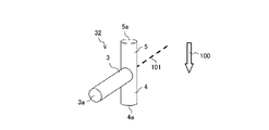
- FIG. 3 is a perspective view showing an example of the first heat exchanger between refrigerants 1 mounted in the refrigeration cycle apparatus 200 according to Embodiment 1.
- the first refrigerant heat exchanger 1 and the second branch portion 32 used in the refrigeration cycle apparatus 200 according to Embodiment 1 will be described with reference to FIG.
- solid line arrows and broken line arrows represent the flow direction of the coolant RF
- white arrows represent the direction of gravity 100 .
- the second branch 32 is connected to the first heat exchanger between refrigerants 1 directly or via another pipe.
- first refrigerant heat exchanger 1 to which the second branch 32 is connected will be described.
- the first heat exchanger between refrigerants 1 is, for example, a plate heat exchanger.
- the first heat exchanger between refrigerants 1 has a main body 1d formed by stacking a plurality of heat transfer plates 1c.
- a high-temperature side passage 1a through which a high-temperature refrigerant flows and a low-temperature side passage 1b through which a refrigerant having a lower temperature than the refrigerant flowing in the high-temperature side passage 1a are formed inside the body portion 1d.
- the refrigerant flowing through the high temperature side flow path 1a and the refrigerant flowing through the low temperature side flow path 1b are separated from each other. and a low temperature side flow path 1b are formed.
- high-temperature side passages 1a and low-temperature side passages 1b are alternately formed with each heat transfer plate 1c of the plurality of heat transfer plates 1c as a boundary.
- the first heat exchanger between refrigerants 1 exchanges heat between the refrigerant flowing through the high temperature side passage 1a and the refrigerant flowing through the low temperature side passage 1b.
- the first heat exchanger between refrigerants 1 may be a plate heat exchanger as long as it is a heat exchanger that exchanges heat between the refrigerant flowing through the high temperature side passage 1a and the refrigerant flowing through the low temperature side passage 1b. is not limited to
- the body portion 1d is formed with a high temperature side channel inlet 51 and a low temperature side channel inlet 53 through which the coolant RF flows when flowing into the body portion 1d. Further, the body portion 1d is formed with a high temperature side flow channel outlet 52 and a low temperature side flow channel outlet 54 through which the coolant RF flows out from the inside of the body portion 1d.
- the high temperature side channel inlet 51 and the high temperature side channel outlet 52 form the inlet and outlet of the high temperature side channel 1a.
- the low temperature side channel inlet 53 and the low temperature side channel outlet 54 form the inlet and outlet of the low temperature side channel 1b.
- the high-temperature-side channel inlet 51 is a refrigerant inlet in the high-temperature-side channel 1 a and serves as an inlet of the refrigerant to the first heat exchanger between refrigerants 1 .
- the high-temperature-side flow path outlet 52 is a refrigerant outlet in the high-temperature-side flow path 1 a and serves as a refrigerant outlet from which the refrigerant flows toward the first branch portion 31 .
- the low temperature side flow path inlet 53 is an inlet of the refrigerant in the low temperature side flow path 1b, and is an inlet of the refrigerant that is branched from the first branch portion 31 and passed through the second expansion device 22 .
- the low-temperature-side channel outlet 54 is a coolant outlet in the low-temperature-side channel 1 b and is an outlet for the coolant flowing toward the second branch portion 32 .
- the high temperature side channel outlet 52 and the low temperature side channel inlet 53 are formed below the low temperature side channel outlet 54 . That is, the refrigerant flow path 20 on the outlet side of the first heat exchanger 1 connected to the first branch portion 31 and the refrigerant flow on the inlet side of the first heat exchanger 1 connected to the second expansion device 22
- the passage 20 is provided below the refrigerant passage 20 on the outlet side of the first heat exchanger 1 between refrigerants, which are both connected to the second branch portion 32 .
- the refrigerant RF is supplied from the outdoor heat exchanger 11, which is the first condenser, to the first heat exchanger between refrigerants 1.
- Refrigerant RF supplied from the outdoor heat exchanger 11 to the first heat exchanger between refrigerants 1 flows into the main body 1d from the high temperature side flow path inlet 51, and flows through the high temperature side flow path 1a formed in the main body 1d. , and flows out of the main body 1d from the high-temperature side flow passage outlet 52.
- the refrigerant RF is branched at the first branch portion 31, a part of the refrigerant RF flows through the main circuit 20a and flows into the first expansion device 21, and a part of the refrigerant RF flows through the bypass circuit 20b and flows into the second It flows into the throttle device 22 .
- the refrigerant flowing through the bypass circuit 20b flows into the main body portion 1d from the low temperature side flow path inlet 53, passes through the low temperature side flow path 1b formed in the main body portion 1d, and reaches the low temperature side. It flows out of the main body portion 1d from the side channel outlet 54 .
- the first heat exchanger between refrigerants 1 heat exchange is performed between the refrigerant flowing through the low-temperature side passage 1b and the refrigerant flowing through the high-temperature side passage 1a.
- the refrigerant RF that has flowed out from the low temperature side flow path outlet 54 flows into the second branch portion 32 .
- the first heat exchanger between refrigerants 1 is a plate-type heat exchanger in which the high temperature side flow path 1a and the low temperature side flow path 1b are alternately laminated
- the high temperature side flow path outlet 52 the positional relationship between the low-temperature-side channel inlet 53 and the low-temperature-side channel outlet 54 is preferably as follows.
- both the high temperature side flow path outlet 52 and the low temperature side flow path inlet 53 may be formed below the low temperature side flow path outlet 54 in the direction of gravity 100. desirable.
- the first heat exchanger between refrigerants 1 makes it easier for the liquid refrigerant to drop from the low temperature side flow path outlet 54 to the low temperature side flow path inlet 53 due to gravity, and the liquid refrigerant flows into the second branch portion 32. can be prevented, and the gas-liquid separation effect is improved.
- FIG. 4 is a perspective view of the second branch portion 32 connected to the first heat exchanger between refrigerants 1 shown in FIG.
- FIG. 5 is a schematic diagram of an example of the second branch portion 32 of FIG. 4 viewed from the cross-sectional side of the inflow pipe 3 .
- the second branch portion 32 shown in FIG. 5 is a horizontal direction perpendicular to the direction of gravity 100 and is a schematic diagram when the second branch portion 32 is viewed in the direction of the vertical line 101 shown in FIG.
- the second branch portion 32 is a branch pipe and has an inflow pipe 3, a liquid outflow pipe 4, and a gas outflow pipe 5.
- the second branch portion 32 is, for example, a two-branch pipe and a T-shaped pipe. It should be noted that the second branch portion 32 is not limited to a T-tube as long as it branches at least the refrigerant RF into two.
- the inflow pipe 3 is a pipe into which the refrigerant RF that has flowed out from the low temperature side flow path outlet 54 after passing through the low temperature side flow path 1b of the first heat exchanger between refrigerants 1 flows.
- the inflow pipe 3 is connected to the low temperature side flow channel outlet 54 directly or via another pipe.
- the liquid outflow pipe 4 and the gas outflow pipe 5 are pipes through which the refrigerant RF flowing from the inflow pipe 3 branches and flows.
- the end of the inflow pipe 3 forms the inflow port 3a for the refrigerant RF
- the end of the liquid outflow pipe 4 forms the outflow port 4a for the refrigerant
- the end of the gas outflow pipe 5 forms the coolant outlet 5a.
- the liquid outflow tube 4 is a tube that forms an outlet for the refrigerant below the gas outflow tube 5 in the direction of gravity 100, and the gas outflow tube 5 is lower than the liquid outflow tube 4 in the direction of gravity. It is a tube forming an outlet for the coolant on the upper side.
- the second branch portion 32 is formed such that the gas outflow pipe 5 is arranged above the liquid outflow pipe 4 and the liquid outflow pipe 4 is arranged below the gas outflow pipe 5 in the direction of gravity 100 . be done.
- the second branch portion 32 has at least one outflow pipe with respect to a horizontal plane 102 perpendicular to the direction of gravity 100 and including the center 3b of the cross section of the inflow pipe 3. It may be provided on the lower side, or at least one outflow tube may be provided on the upper side.
- the second branch portion 32 is preferably provided with the liquid outflow pipe 4 below the horizontal surface 102 and the gas outflow pipe 5 above the horizontal surface 102 .
- the axial direction of the liquid outflow tube 4 or the axial direction of the gas outflow tube 5 may be inclined with respect to the horizontal plane 102 .
- the inflow pipe 3 of the second branch portion 32 is formed in a straight pipe shape, and is connected to the low temperature side flow path outlet 54 of the first heat exchanger between refrigerants 1 .
- the second branch portion 32 is not limited to this configuration, and may be provided with a bent tube as long as the relative positional relationship of the liquid outflow tube 4 to the gas outflow tube 5 is on the lower side. Also, different branch channels may be provided.
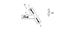
- FIG. 6 is a cross-sectional view schematically showing a cross-section of the second branching portion 32 for explaining the flow of the refrigerant in the second branching portion 32.
- FIG. 6 is a vertical cross-sectional view of the second branch portion 32 along the pipe axis direction, and is a cross-sectional view of the second branch portion 32 taken along line AA in FIG.
- a refrigerant flow GRF shown in FIG. 6 indicates the flow of the gas-based refrigerant 62
- a refrigerant flow LRF indicates the flow of the liquid-based refrigerant 61 .
- the flow of the coolant RF in the second branch portion 32 will be described with reference to FIG. 6 .
- the refrigerant RF flowing from the inflow pipe 3 is branched by the liquid outflow pipe 4 and the gas outflow pipe 5 and flows out from the outflow port 4 a of the liquid outflow pipe 4 and the outflow port 5 a of the gas outflow pipe 5 .
- the gas-liquid two-phase refrigerant RF flowing from the inflow pipe 3 flows into the liquid outflow pipe 4 arranged below the gas outflow pipe 5 at the second branch portion 32, where the liquid-based refrigerant 61 is affected by gravity.
- the stream is diverted so as to head toward the river.
- the liquid-based refrigerant 61 is a refrigerant containing a large amount of liquid refrigerant 63 having a relatively high density.
- gas-liquid two-phase refrigerant RF flowing from the inflow pipe 3 is directed toward the gas outflow pipe 5 arranged above the liquid outflow pipe 4 due to the buoyancy of the gas-based refrigerant 62 at the second branch portion 32. diverted.
- the gas-based refrigerant 62 is a refrigerant containing more gas refrigerant 64 with a relatively low density than the liquid refrigerant 63 .
- FIG. 7 is a schematic diagram showing a first modification of the second branch portion 32.
- FIG. FIG. 8 is a schematic diagram showing a second modification of the second branch portion 32.
- the second branch portion 32 is integrally formed with the liquid outflow tube 4 and the gas outflow tube 5, and the liquid outflow tube 4 and the gas outflow tube 5 formed in straight tubes extend in the direction of gravity. It is not limited to a configuration formed to extend 100 degrees.
- the second branch portion 32 may be formed such that the straight liquid outflow pipe 4 and the straight gas outflow pipe 5 are inclined with respect to the direction of gravity 100 .
- the direction in which the coolant RF flows through the inflow pipe 3 is different from the direction in which the coolant RF flows through the gas outflow pipe 5. It may also be formed to have components in opposite directions.
- the second branch portion 32 has a component in which the direction of flow of the coolant RF flowing through the inflow pipe 3 is the same as the direction of flow of the coolant RF flowing through the inflow pipe 3. It may be formed as
- the direction in which the coolant RF flows in the inflow pipe 3 is different from the direction in which the coolant RF flows in the liquid outflow pipe 4. It may also be formed to have components in opposite directions.
- the second branch portion 32 has a component in which the direction of flow of the refrigerant RF flowing through the inflow pipe 3 is the same as the direction of flow of the refrigerant RF flowing through the inflow pipe 3 . It may be formed as
- FIG. 9 is a schematic diagram showing a third modified example of the second branch portion 32.
- the second branch portion 32 has a structure in which the liquid outflow pipe 4 and the gas outflow pipe 5 are integrally formed, and the liquid outflow pipe 4 and the gas outflow pipe 5 are formed in a straight pipe shape. It is not limited.
- the second branch portion 32 may be integrally formed with the inflow pipe 3 and the gas outflow pipe 5, and the inflow pipe 3 and the gas outflow pipe 5 may be formed in a straight pipe shape.
- the liquid outflow pipe 4 is connected to the straight inflow pipe 3 and the gas outflow pipe 5 and extends downward from the straight inflow pipe 3 and the gas outflow pipe 5 .
- the outflow port 4a of the liquid outflow pipe 4 faces downward.
- FIG. 10 is a schematic diagram showing a fourth modified example of the second branch portion 32.
- the second branch portion 32 has a structure in which the liquid outflow pipe 4 and the gas outflow pipe 5 are integrally formed, and the liquid outflow pipe 4 and the gas outflow pipe 5 are formed in a straight pipe shape.
- the inflow pipe 3 and the liquid outflow pipe 4 may be integrally formed in the second branch portion 32, and the inflow pipe 3 and the liquid outflow pipe 4 may be formed in a straight pipe shape.
- the gas outflow pipe 5 is connected to the straight inflow pipe 3 and the liquid outflow pipe 4 and extends upward from the straight inflow pipe 3 and the liquid outflow pipe 4 .
- the outflow port 5a of the gas outflow pipe 5 faces upward.
- FIG. 11 is a schematic diagram showing a fifth modification of the second branch portion 32.
- the second branch portion 32 is not limited to the T-shaped tube described above, and may be formed in a Y-shape as shown in FIG. 11 . Moreover, as shown in FIG. 11, the second branch portion 32 may be formed in a U-shape at the liquid outflow tube 4 and the gas outflow tube 5 .
- FIG. 12 is a schematic diagram showing a sixth modification of the second branch portion 32.
- the second branch portion 32 of the sixth modified example shown in FIG. may be configured to have a portion that is larger than the diameter R2 of .
- the second branch portion 32 of the sixth modified example has an enlarged portion 8 between the liquid outflow pipe 4 and the gas outflow pipe 5 .
- the enlarged portion 8 is formed in a cylindrical shape, and a space V is formed inside.
- the enlarged portion 8 has a body portion 8a and two lid portions 8b.
- the main body part 8a is a tubular member.
- the body portion 8a of the second branch portion 32 is desirably installed so that the tube axis 8c is in the direction of gravity 100.
- the tube axis 8c of the main body 8a may be inclined with respect to the direction of gravity 100, but at least the tube axis 8c is installed in a state of being inclined within a range having a vector component in the direction of gravity 100.
- the inflow pipe 3 is connected to the body portion 8a. Further, a through hole 8d is formed in the body portion 8a. 8 d of through-holes are holes which penetrate the main-body part 8a. The inflow pipe 3 is connected to the portion forming the through hole 8d. The second branch portion 32 is formed so that the space inside the inflow pipe 3 and the space V inside the enlarged portion 8 communicate with each other through the through hole 8d.
- the two lid portions 8b close both ends of the body portion 8a in the direction of the tube axis 8c so as to form a space V inside the body portion 8a.
- Each of the two lid portions 8b is formed in a plate shape.
- An opening 8b1 is formed in each of the two lids 8b.
- the opening 8b1 is a hole passing through the lid 8b.
- a gas outflow pipe 5 is connected to a portion forming the opening 8b1 of the upper lid portion 8b
- a liquid outflow pipe 4 is connected to a portion forming the opening 8b1 of the lower lid portion 8b. is connected. That is, in the second branch portion 32 , the gas outflow pipe 5 extends upward from the enlarged portion 8 , and the liquid outflow pipe 4 extends downward from the enlarged portion 8 .
- the second branch portion 32 is formed so that the space inside the gas outflow pipe 5 and the space V inside the main body portion 8a communicate with each other through the opening portion 8b1 of the upper lid portion 8b.
- the second branch portion 32 is formed so that the inner space of the liquid outflow pipe 4 and the space V inside the main body portion 8a communicate with each other through the opening portion 8b1 of the lower cover portion 8b.
- the second branch portion 32 is formed such that the diameter R1 of the flow passage cross section of the enlarged portion 8 is larger than the diameter R2 of the flow passage cross sections of the liquid outflow pipe 4 and the gas outflow pipe 5 .
- the diameter R1 of the flow passage cross section of the enlarged portion 8 is the inner diameter of the enlarged portion 8
- the diameter R2 of the flow passage cross sections of the liquid outflow tube 4 and the gas outflow tube 5 is the inner diameter of the liquid outflow tube 4 and the gas outflow tube. 5 inside diameter.
- the diameters of the cross sections of the liquid outflow tube 4 and the gas outflow tube 5 are R2, respectively, which are the same size, but the flow cross sections of the liquid outflow tube 4 and the gas outflow tube 5 may be of different sizes.
- the cross-sectional diameters of the liquid outflow tube 4 and the gas outflow tube 5 are smaller than the diameter of the cross-section of the enlarged portion 8 . That is, the diameter of the cross-section of the enlarged portion 8 is larger than the diameter of the cross-section of the liquid outflow tube 4 and the gas outflow tube 5 .
- the second branch portion 32 is formed such that the diameter R1 of the flow passage cross section of the enlarged portion 8 is larger than the diameter R3 of the flow passage cross section of the inflow pipe 3 .
- the diameter R3 of the cross section of the inflow pipe 3 is the inner diameter of the inflow pipe 3 .
- the diameter of the cross section of the enlarged portion 8 is larger than the diameter of the cross sections of the liquid outflow pipe 4 and the gas outflow pipe 5 . Further, the second branch portion 32 of the sixth modified example is formed such that the diameter of the cross section of the enlarged portion 8 is larger than the diameter of the cross section of the inflow pipe 3 .
- the second branch part 32 of the sixth modification can be a volumetric gas-liquid separation device by having this configuration, and the gas-liquid separation effect is increased compared to the case without this configuration. be able to.
- a volume type gas-liquid separation device is a gas-liquid separation device having a structural part with a pipe diameter larger than the inlet/outlet pipe such as the inflow pipe 3, the liquid outflow pipe 4, and the gas outflow pipe 5 in the second branch part 32.
- the enlarged portion 8 is a structural portion having a pipe diameter larger than that of the entrance/exit pipe such as the inflow pipe 3, the liquid outflow pipe 4, and the gas outflow pipe 5.
- the second branch portion 32 of the sixth modification can improve the separation between the liquid-based refrigerant and the gas-based refrigerant by having the expanded portion 8 . More specifically, the refrigerant that has entered the expanded portion 8 from the inflow pipe 3 enters the expanded portion 8 having a larger cross-sectional area than the inflow pipe 3, and the flow velocity decreases, and the gas-liquid two-phase refrigerant enters the expanded portion 8. collides with the inner wall of the The liquid phase component of the refrigerant that collides with the inner wall of the enlarged portion 8 due to a decrease in flow velocity drops and flows out of the second branch portion 32 from the liquid outflow pipe 4, and the remaining gas phase component flows into the liquid outflow pipe 4. separated to flow out from a gas outflow pipe 5 arranged above.
- the gas-liquid two-phase mixed refrigerant is affected by a force other than the inertial force that causes the gas-liquid mixture to flow in the same direction, in this case gravity. As it becomes larger, it becomes easier to separate vertically.
- the second branching portion 32 of the sixth modified example separates the gas phase and the liquid phase of the refrigerant by centrifugal force by swirling the refrigerant in the expansion portion 8 in addition to separation by gravity. and liquid phase separation can be used.
- the expanded portion 8 has a larger inner diameter than the inflow pipe 3, the liquid outflow pipe 4 and the gas outflow pipe 5, and the inflow pipe 3, the liquid outflow pipe 4 and the gas outflow pipe 5 It has a larger surface area than the gas outflow tube 5 .
- the second branch portion 32 of the sixth modification has a larger surface area than the inflow pipe 3, the liquid outflow pipe 4, and the gas outflow pipe 5, as well as separation due to gravity, with respect to the separation of the gas phase and the liquid phase of the refrigerant.
- the surface tension of the portion 8 or the like can be used.
- the refrigeration cycle device 200 suppresses mixing of liquid refrigerant into the compressor 14 by supplying the gas-based refrigerant to the fourth branch portion 34 that joins at a position closer to the compressor 14 than the third branch portion 33 , thereby preventing refrigeration.
- the performance of the cycle device 200 is enhanced.
- the refrigeration cycle apparatus 200 of Embodiment 1 is configured such that the refrigerant flowing through the bypass circuit 20b is divided into the liquid-based refrigerant 61 and the gas-based refrigerant 62 at the second branch portion 32.
- the refrigerating cycle device 200 is configured such that the refrigerant branched in the bypass circuit 20b joins the main stream flowing through the main circuit 20a at the third branch portion 33 and the fourth branch portion 34 of the main circuit 20a.
- a refrigerant tank 6 is provided between the third branch portion 33 and the fourth branch portion 34 in the refrigeration cycle apparatus 200 according to Embodiment 1 shown in FIGS. 1 and 2 .
- the refrigerant that joins the liquid-based refrigerant 61 at the third branch portion 33 is phase-separated in the refrigerant tank 6, and the refrigerant flowing out of the refrigerant tank 6 joins the gas-based refrigerant 62 at the fourth branch portion 34. It is supplied to the compressor 14 .
- the refrigeration cycle device 200 includes a liquid outflow pipe 4 forming a refrigerant outlet below the gas outflow pipe 5 and a gas outflow pipe 5 forming another refrigerant outlet above the liquid outflow pipe 4. and for branching the refrigerant into two.
- the second branch portion 32 has a gas outflow pipe 5 and a liquid outflow pipe 4 arranged vertically in the direction of gravity.
- a liquid main refrigerant 61 having a dryness lower than that of the main refrigerant 62 is separated into the liquid outflow tube 4 .
- the refrigerating cycle device 200 supplies the separated refrigerants to the main circuit 20a from the indoor heat exchanger 16, which is the first evaporator, to the discharge port 14b of the compressor 14, respectively.
- the refrigeration cycle device 200 can increase the refrigerant flow rate of the bypass circuit 20b without excessively supplying the liquid refrigerant to the suction port 14a of the compressor 14 . Therefore, the refrigeration cycle apparatus 200 can improve compressor performance and energy saving performance without enlarging the equipment, and can achieve both compressor performance and energy saving performance and securing of space required for equipment installation.
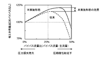
- FIG. 13 is a graph conceptually comparing the energy saving performance ratio with respect to the bypass flow rate ratio of the refrigeration cycle device.
- the horizontal axis of FIG. 13 indicates the bypass flow rate ratio, and the vertical axis indicates the energy saving performance ratio for the operation without the bypass.
- the bypass flow rate ratio indicates the bypass flow rate with respect to the main flow rate.
- the main flow rate is the flow rate of refrigerant flowing through the main circuit 20a
- the bypass flow rate is the flow rate of refrigerant flowing through the bypass circuit 20b.
- a solid line in FIG. 13 indicates the performance improvement effect of the refrigeration cycle apparatus 200 according to the first embodiment.
- the dashed line in FIG. 13 indicates the performance of a conventional refrigeration cycle apparatus in which gas-liquid separation is not performed at the second branch portion 32, and the apparatus size is the same.
- Embodiment 1 The effect of the refrigeration cycle device 200 according to Embodiment 1 will be described using FIG.
- the compressor undergoes liquid compression, which degrades the performance of the compressor and causes equipment failure. Therefore, in order to sufficiently phase-separate the refrigerant supplied to the compressor, the refrigerant tank connected to the suction side of the compressor may be enlarged.
- the gas-based refrigerant 62 joins at the fourth branch portion 34 .
- the refrigeration cycle device 200 separates the liquid-based refrigerant 61 and the gas-based refrigerant 62 at the second branch portion 32, and passes the liquid-based refrigerant 61 side through the refrigerant tank 6 to remove the liquid refrigerant and then the fourth branch. It joins with the gas-based refrigerant 62 at the portion 34 . Therefore, in the refrigeration cycle device 200, the liquid flow rate of the refrigerant supplied to the compressor 14 per liquid refrigerant discharged in the refrigerant tank 6 is reduced, and the refrigerant tank 6 does not need to be enlarged.
- the refrigeration cycle device 200 can improve the performance by increasing the flow rate of the refrigerant flowing through the bypass circuit 20b and reducing the pressure loss caused by the refrigerant flowing through the main circuit 20a.
- the fourth branch portion 34 is located downstream of the third branch portion 33, a certain volume is generated between the third branch portion 33 and the fourth branch portion 34. Therefore, a low load with a particularly low circulation rate is achieved.
- liquid stays in the low pressure piping.
- the liquid stays in the low-pressure pipe, and the gas-based refrigerant flows into the compressor 14. Therefore, compared with a configuration in which the liquid refrigerant directly flows into the compressor, the performance is improved.
- the configuration of the refrigeration cycle device 200 indicated by the solid line in FIG. 13 can reduce the amount of liquid refrigerant supplied to the compressor 14 and improve the bypass flow rate compared to the conventional configuration, thereby improving the energy saving performance.
- the configuration of the refrigeration cycle device 200 includes the refrigerant tank 6 between the third branch portion 33 and the fourth branch portion 34 . Therefore, the configuration of the refrigeration cycle device 200 reduces the flow rate of the refrigerant flowing out of the refrigerant tank 6 compared to the case where the fourth branch portion 34 is not provided, and reduces the inertial force of the refrigerant and the shaking of the liquid surface in the refrigerant tank 6 . Reduces the amount of liquid refrigerant mixed in.
- Refrigerant flowing out from the refrigerant tank 6 in which the refrigerant flow rate is reduced and the amount of liquid refrigerant is reduced joins with the gas-based refrigerant 62 at the fourth branch portion 34, whereby the amount of liquid refrigerant supplied to the compressor 14 is reduced.
- the outdoor heat exchanger 11 and the indoor heat exchanger 16 operate as an evaporator and a condenser by switching between cooling and heating.
- the refrigeration cycle apparatus 200 can increase the refrigerant flow rate during condenser operation relative to the refrigerant flow rate during evaporator operation when operating as an evaporator and a condenser. Therefore, the refrigerating cycle device 200 can improve the heat transfer in the tube in the condenser operation per the refrigerant pressure loss in the evaporator operation, so that the performance of both the cooling operation and the heating operation can be improved.
- the refrigeration cycle device 200 can expand the flow rate adjustment range of the bypass flow of the refrigerant flowing through the bypass circuit 20b due to the above configuration. Since the refrigeration cycle device 200 can expand the flow rate adjustment range of the bypass flow of the refrigerant flowing through the bypass circuit 20b, the refrigerant flow rate flowing to the evaporator at 100% of the cooling and heating capacity of the device and the cooling and heating capacity of the device 100% or less, especially the cooling and heating capacity The difference from the refrigerant flow rate of 25% to 80% can be reduced.
- the refrigeration cycle device 200 can reduce the difference in refrigerant flow rate due to the difference in the cooling and heating capacity of the equipment, it is possible to narrow the flow rate design range of the components of the equipment whose performance largely depends on the refrigerant flow velocity.
- Equipment components whose performance greatly depends on the flow velocity of the refrigerant are, for example, the outdoor heat exchanger 11, the indoor heat exchanger 16, the refrigerant tank 6, and the like. Since the refrigeration cycle device 200 can reduce the flow rate design range of the components of the equipment whose performance largely depends on the refrigerant flow rate, the performance of intermediate load operation can be improved, and the period efficiency of the refrigeration cycle device 200 whose operating load changes throughout the year. can be improved.
- bypass flow rate ratio and performance improvement rate that maximize performance vary depending on the operating capacity for the equipment size and the refrigerant type of the working fluid. the effect is the same. For example, the performance improvement effect is greater in equipment with a long extension pipe from the outdoor unit to the indoor unit or in equipment with high operability.
- a working fluid containing at least a portion of a refrigerant having a gas density lower than that of the R32 refrigerant has a high refrigerant flow velocity per capacity, and therefore has a large effect of improving performance by reducing pressure loss.
- the refrigerant flowing through the main circuit 20a and the bypass circuit 20b has a lower gas density than the R32 refrigerant.
- This refrigerant is, for example, a refrigerant containing at least one of olefinic refrigerants such as tetrafluoropropene, ethylene refrigerants such as difluoroethylene, ethane refrigerants such as tetrafluoroethane, propane, and DME (dimethyl ether).
- the olefinic refrigerant include HFO1234yf, HFO1234ze(E), and the like.
- the main stream of the refrigerant flowing through the main circuit 20a is the high boiling point component in the third branch portion 33. It merges with the main refrigerant and undergoes phase separation in the refrigerant tank 6 . Since the high boiling point refrigerant is stored as a liquid refrigerant in the refrigerant tank 6 and the low boiling point main refrigerant flows into the compressor 14, the low boiling point main refrigerant circulates through the refrigerant flow path 20 and the performance of the refrigeration cycle device 200 is improved.
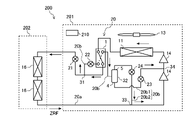
- FIG. 14 is a refrigerant circuit diagram showing a first modification of the refrigeration cycle device 200 according to Embodiment 1.
- FIG. FIG. 15 is a refrigerant circuit diagram showing a second modification of the refrigeration cycle device 200 according to Embodiment 1.
- solid line arrows and broken line arrows represent the flow direction of the refrigerant RF, and particularly the flow of the non-azeotropic mixed refrigerant ZRF.
- dotted line arrows shown in the repeater unit 203 represent the flow of the water WF.
- a refrigerating cycle device 200 shown in FIGS. 14 and 15 has a fifth expansion device 25 provided between two indoor heat exchangers 16 . Further, the refrigeration cycle device 200 shown in FIG. and a sixth throttle device 26 provided in a pipe provided to connect the .
- the fifth expansion device 25 and the sixth expansion device 26 function as pressure reducing valves or expansion valves to expand and reduce the pressure of the refrigerant, and the first expansion device 21 and the second expansion device 22 may be used.
- the indoor heat exchanger 16 may be a repeater unit 203 that conveys the heat medium to the indoor unit 202.
- the number of outdoor unit 201, indoor unit 202 (see FIGS. 1 and 2), and repeater unit 203 may be two or more.
- the outdoor unit 201, the indoor unit 202 (see FIGS. 1 and 2), and the relay unit 203 may be connected in series or in parallel when viewed from the refrigerant flow.
- the outdoor unit 201 is equipped with the outdoor heat exchanger 11, the indoor unit 202 is equipped with the indoor heat exchanger 16 (see FIGS. 1 and 2), or the repeater unit 203 is equipped with an indoor heat exchanger. Exchanger 16 is mounted.
- the indoor unit 202 is equipped with the second indoor heat exchanger 12 or the third indoor heat exchanger 17 (see FIGS. 22 and 23).
- the outdoor heat exchanger 11, the second indoor heat exchanger 12, the indoor heat exchanger 16, and the third indoor heat exchanger 17 may be connected in series or in parallel when viewed from the refrigerant flow. .
- FIG. 16 is a schematic diagram showing a refrigeration cycle apparatus 200 according to Embodiment 2.
- FIG. 16 solid arrows indicate the flow direction of the refrigerant RF, particularly the flow of the single-composition refrigerant or the azeotropic mixture refrigerant ARF.
- a refrigeration cycle apparatus 200 according to Embodiment 2 will be described using FIG. 16 .
- a refrigerating cycle device 200 according to Embodiment 2 is obtained by partially changing the refrigerating cycle device 200 according to Embodiment 1, and the basic overall configuration is the same as that of the refrigerating cycle device 200 according to Embodiment 1. Configuration. Therefore, in the refrigerating cycle apparatus 200 according to the second embodiment shown in FIG. The explanation is omitted.
- a refrigeration cycle apparatus 200 according to Embodiment 2 has two compressors 14 as shown in FIG. The two compressors 14 are connected in series in the direction in which the refrigerant flows.
- a refrigeration cycle apparatus 200 according to Embodiment 2 has a fourth branch portion 34 between two different compressors 14 located downstream of the third branch portion 33 in the refrigerant flow direction.
- the refrigeration cycle device 200 provides the fourth branch 34 connected to the gas outflow pipe 5 in the refrigerant compression process, thereby improving the gas ratio of the refrigerant supplied to the compressor 14 downstream of the fourth branch 34 .
- the compressor undergoes liquid compression and performance is lowered.
- equipment such as a refrigerant tank or a preheating structure may be added to the refrigeration cycle apparatus.
- the refrigeration cycle apparatus 200 according to Embodiment 2 the main stream of refrigerant flowing through the main circuit 20 a joins the gas-based refrigerant 62 at the fourth branch portion 34 . Therefore, the refrigeration cycle device 200 can reduce the flow rate of the liquid supplied to the refrigerant compression process without adding equipment. In addition, the refrigeration cycle device 200 can improve the performance by increasing the bypass flow rate and reducing the pressure loss of the mainstream.
- FIG. 17 shows a modification of the refrigeration cycle device 200 according to the second embodiment.
- solid arrows indicate the flow direction of the refrigerant RF, particularly the flow of the single composition refrigerant or the azeotropic mixture refrigerant ARF.
- the compressor 14 is arranged downstream of the compressor 14 arranged upstream of the fourth branch 34 as shown in FIG.
- the compressor 14 may be configured integrally.
- the fourth branch 34 may then be formed as the injection port 7 of the compressor 14 .
- the injection port 7 is formed so as to communicate with a compression chamber (not shown) of the compressor 14 .
- the injection port 7 is a through hole formed in the compressor 14 and is used to forcibly inject gas-liquid two-phase refrigerant or the like into the compression chamber of the compressor 14 .
- the injection port 7 is, for example, an intermediate pressure injection port that communicates with a portion that constitutes an intermediate pressure in the compression chamber.
- the refrigeration cycle device 200 improves the gas ratio of the refrigerant supplied to the compressor 14 through the injection port 7 by providing the fourth branch portion 34 connected to the gas outflow pipe 5 in the refrigerant compression process.
- the compressor undergoes liquid compression and performance is lowered.
- equipment such as a refrigerant tank or a preheating structure may be added to the refrigeration cycle apparatus.
- the main stream of refrigerant flowing through the main circuit 20 a joins the gas-based refrigerant 62 at the fourth branch portion 34 . Therefore, the refrigeration cycle device 200 can reduce the flow rate of the liquid supplied to the refrigerant compression process without adding equipment.
- the refrigeration cycle device 200 can improve the performance by increasing the bypass flow rate and reducing the pressure loss of the mainstream.
- the refrigerating cycle device may have additional equipment such as a refrigerant tank or a preheating structure provided upstream of the injection port.
- a refrigeration cycle apparatus 200 according to Embodiment 2 shown in FIG. Therefore, the refrigeration cycle device 200 can reduce the flow rate of the liquid supplied to the refrigerant compression process, improve the bypass flow rate without adding equipment, reduce the pressure loss of the mainstream, and improve performance.
- the low-pressure side compressor 14 or More high-boiling components flow into the compression chamber (not shown).
- the amount of high-boiling-point components flowing into the low-pressure-side compressor 14 or the compression chamber (not shown) increases, and there is no deterioration in performance due to an increase in pressure loss. Great improvement.
- FIG. 18 is a schematic diagram showing a refrigeration cycle apparatus 200 according to Embodiment 3.
- FIG. FIG. 19 is a cross-sectional view schematically showing a cross-section of the second branch portion 32 for explaining the flow of refrigerant in the second branch portion 32.
- solid arrows indicate the direction of flow of the refrigerant RF, particularly the flow of the non-azeotropic mixed refrigerant ZRF.
- Refrigerant flow HBRF shown in FIG. 19 indicates the flow of the high boiling point main refrigerant 67
- refrigerant flow LBRF indicates the flow of the low boiling point main refrigerant 68.
- FIG. 18 does not show the refrigerant flow path 20 during the heating operation, and only shows the refrigerant flow path 20 during the cooling operation for ease of viewing.
- a refrigeration cycle apparatus 200 according to Embodiment 3 will be described with reference to FIGS. 18 and 19.
- FIG. 18
- a refrigerating cycle device 200 according to Embodiment 3 is obtained by partially changing the refrigerating cycle device 200 according to Embodiment 1, and the basic overall configuration is the same as that of the refrigerating cycle device 200 according to Embodiment 1. is the configuration. Therefore, in the refrigerating cycle apparatus 200 according to the third embodiment shown in FIG. Description is omitted.
- the refrigeration cycle device 200 according to Embodiment 3 uses, as a working fluid, a non-azeotropic mixed refrigerant in which at least two types of refrigerants having normal boiling points different from each other by 1°C or more are mixed.
- a non-azeotropic mixed refrigerant in which at least two types of refrigerants having normal boiling points different from each other by 1°C or more are mixed.
- the gas outflow pipe 5 of the second branch portion 32 is connected to the third branch portion 33
- the liquid outflow pipe 4 is connected to the fourth branch portion. 34.
- a third throttle device 23 is provided in the first branch passage 20b1.
- a fourth expansion device 24 is provided in the second branch passage 20b2.
- the third branch portion 33 is a portion that connects the second branch passage 20b2 of the bypass circuit 20b and the main circuit 20a.
- the third branch portion 33 is a portion that joins the refrigerant flowing through the second branch passage 20b2 of the bypass circuit 20b to the main circuit 20a.
- the fourth branch 34 is arranged between the third branch 33 and the compressor 14 on the inner downstream side of the two compressors 14 .
- the fourth branch portion 34 is a portion that connects the first branch passage 20b1 of the bypass circuit 20b and the main circuit 20a.
- the fourth branch portion 34 is a portion that joins the refrigerant flowing through the first branch passage 20b1 of the bypass circuit 20b to the main circuit 20a.
- the fourth branch portion 34 is arranged between the compressor 14 and the third branch portion 33 .
- a refrigeration cycle apparatus 200 according to Embodiment 3 has a fourth branch portion 34 between two different compressors 14 located downstream of the third branch portion 33, as shown in FIG.
- Embodiment 3 In general, in a refrigeration cycle device using a non-azeotropic mixed refrigerant as a working fluid, when a refrigerant containing a large amount of high-boiling-point refrigerant flows into the low-pressure suction port of the compressor, the pressure loss and volumetric flow rate at the suction port of the compressor increase. . Therefore, in the refrigerant cycle device, in order to maintain the performance, there are cases where the compressor is enlarged to have a large capacity, or the refrigerant tank is enlarged and a high-boiling-point refrigerant is stored in the refrigerant tank.
- the two-phase non-azeotropic mixed refrigerant (bypass flow) flowing through the bypass circuit 20 b is separated at the second branch portion 32 .
- the liquid refrigerant 65 of the refrigerant RF flowing into the second branch portion 32 contains many high boiling point components, and the gas refrigerant 66 contains many low boiling point components.
- the gas outflow is A large amount of the low-boiling-point main refrigerant 68 flows out from the outlet 5 a of the pipe 5 .
- the high-boiling-point main refrigerant 67 is a refrigerant containing a large amount of the liquid refrigerant 65 having a relatively high density, and is a refrigerant containing a large amount of high-boiling-point components.
- the low-boiling-point main refrigerant 68 is a refrigerant containing a large amount of the gas refrigerant 66 having a relatively low density, and is a refrigerant containing a large amount of low-boiling-point components.
- a high boiling point main refrigerant 67 flowing out from the outlet 4a of the liquid outlet pipe 4 is supplied to the fourth branch portion 34, and a low boiling point main refrigerant 68 flowing out from the outlet 5a of the gas outlet pipe 5 is supplied to the third branch portion 33. supplied to
- the refrigeration cycle device 200 has a lower pressure at the position of the third branching portion 33 than at the position of the fourth branching portion 34 .
- the refrigeration cycle device 200 according to Embodiment 3 supplies the low boiling point main refrigerant 68 to the low pressure side compressor 14 by supplying the low boiling point main refrigerant 68 to the third branch portion 33, thereby supplying the low boiling point main refrigerant 68 to the high boiling point main refrigerant 67.
- the fourth branch portion 34 the high-boiling-point main refrigerant 67 is supplied to the compressor 14 on the high-pressure side.
- the refrigeration cycle apparatus 200 according to Embodiment 3 can suppress an increase in the pressure loss of the low-pressure side compressor 14 by having this configuration, and can improve the energy saving performance without increasing the size of the equipment. Further, when the temperature difference of the mixed refrigerant used in the refrigeration cycle device 200 is 5° C. or more, the composition separation effect due to the gas-liquid separation becomes large, so the performance improvement effect is particularly large. ⁇ Configuration of Modified Example of Embodiment 3>
- FIG. 20 is a schematic diagram showing a first modification of the refrigeration cycle apparatus 200 according to Embodiment 3.
- FIG. 21 is a schematic diagram showing a second modification of the refrigeration cycle apparatus 200 according to Embodiment 3.
- solid line arrows indicate the flow direction of the refrigerant RF, particularly the flow of the non-azeotropic mixed refrigerant ZRF.
- the refrigerant flow paths 20 during the heating operation are omitted and only the refrigerant flow paths 20 during the cooling operation are shown for ease of viewing.
- the refrigeration cycle device 200 uses, as a working fluid, a non-azeotropic mixed refrigerant mixture of at least two types of refrigerants with a normal boiling point difference of 1°C or more.
- the gas outflow pipe 5 is connected to the third branch portion 33, and the liquid outflow pipe 4 is connected to It is connected to the fourth branch portion 34 .
- the fourth branch portion 34 is the injection port 7 of the compressor 14 .
- the refrigeration cycle device 200 has the second heat exchanger 2 between refrigerants.
- the second heat exchanger 2 has two flow paths through which the refrigerant flows.
- the second heat exchanger between refrigerants 2 includes a refrigerant flowing through a flow path from the outdoor heat exchanger 11 of the main circuit 20a to the first expansion device 21, and a flow path from the liquid outflow pipe 4 to the fourth branch portion 34. heat exchange with the flowing refrigerant.
- the outdoor heat exchanger 11 is a first condenser.
- the first refrigerant heat exchanger 1 moves toward the second refrigerant heat exchanger 2 in the flow direction of the refrigerant flowing through the high-temperature side flow path 1a of the first refrigerant heat exchanger 1. It is provided so as to be positioned downstream with respect to.
- the refrigerating cycle device 200 adjusts the opening degree of the fourth expansion device 24 provided between the second branch portion 32 and the third branch portion 33 to achieve the first
- the heat exchange amount ratio between the heat exchanger 1 between refrigerants and the heat exchanger 2 between second refrigerants is controlled.
- the first heat exchanger between refrigerants 1 and the second heat exchanger between refrigerants 2 are defined by the low temperature side flow path 1b of the first heat exchanger between refrigerants 1 and the low temperature side flow path of the second heat exchanger between refrigerants 2. 1b do not merge, it may be configured as an integrated heat exchanger between refrigerants.
- the position of the fourth branch portion 34 is in the compression process, and the position of the third branch portion 33 is relative to the position of the fourth branch portion 34.
- Low pressure The refrigeration cycle device 200 according to the first modification and the second modification supplies the low boiling point main refrigerant 68 to the low pressure side in the compressor 14 by supplying the low boiling point main refrigerant 68 to the third branch portion 33. supply.
- the high boiling point main refrigerant 67 is supplied to the fourth branch portion 34 so that the high boiling point main refrigerant is supplied to the high pressure side in the compressor 14 . 67 supplies.
- the refrigerating cycle apparatus 200 suppresses an increase in the pressure loss of the compressor 14 on the low-pressure side by having this configuration, and achieves energy-saving performance without increasing the size of the equipment. can be improved. Further, when the temperature difference of the mixed refrigerant used in the refrigeration cycle device 200 is 5° C. or more, the composition separation effect due to the gas-liquid separation becomes large, so the performance improvement effect is particularly large.
- the refrigeration cycle device 200 according to the first and second modifications is provided with the second heat exchanger 2 between refrigerants, so that the liquid-based refrigerant 61 separated at the second branch portion 32 The high boiling point main refrigerant 67 is heated and supplied to the fourth branch portion 34 . Therefore, the refrigeration cycle devices 200 according to the first and second modifications reduce the high boiling point components flowing into the third branch portion 33 without increasing the amount of liquid refrigerant flowing into the compression process of the compressor 14. This improves the performance of the compressor 14 and improves energy efficiency.
- a second modified refrigeration cycle apparatus 200 shown in FIG. 21 can be operated by switching between cooling operation and heating operation.
- the refrigeration cycle apparatus 200 of the second modification both the cooling operation and the heating operation are viewed from the high temperature side refrigerant flow of the refrigerant heat exchanger, the first refrigerant heat exchanger 1 is the second refrigerant heat exchanger 2 is provided downstream with respect to
- the refrigeration cycle device 200 of the second modification can ensure both cooling and heating the temperature difference between the high boiling point main refrigerant 67 separated by the second branch portion 32 and the high temperature side refrigerant. It is possible to improve the performance during cooling and heating operation without deteriorating.
- the refrigerating cycle device 200 of the second modification can secure a larger temperature difference between the high-boiling-point main refrigerant 67 and the high-temperature-side refrigerant, so that the performance during cooling and heating operations can be improved without increasing the equipment size. can improve.
- FIG. 22 is a first schematic diagram showing a refrigeration cycle apparatus 200 according to Embodiment 4.
- FIG. FIG. 23 is a second schematic diagram showing a refrigeration cycle apparatus 200 according to Embodiment 4.
- solid arrows indicate the direction of flow of the refrigerant RF, particularly the flow of the non-azeotropic mixed refrigerant ZRF.
- the refrigerant flow paths 20 are omitted for ease of viewing, and the refrigerant flow paths 20 during cooling-main operation or heating-main operation are shown.
- a refrigeration cycle apparatus 200 according to Embodiment 4 will be described with reference to FIGS. 22 and 23.
- a refrigerating cycle device 200 according to Embodiment 4 is obtained by partially changing the refrigerating cycle device 200 according to Embodiment 1, and the basic overall configuration is the same as that of the refrigerating cycle device 200 according to Embodiment 1. is the configuration. Therefore, with regard to the refrigeration cycle apparatus 200 of the fourth embodiment shown in FIGS. 22 and 23, the same reference numerals are given to the same components as those of the refrigeration cycle apparatus 200 according to the first embodiment, or the corresponding components. Illustration and description thereof are omitted.
- the refrigeration cycle device 200 according to Embodiment 4 is capable of mixed operation in which both cooling operation and heating operation are mixed.
- the main circuit 20a and the bypass circuit 20b are configured as a refrigerant circuit in which mixed operation of cooling operation and heating operation is performed.
- a refrigeration cycle device 200 according to Embodiment 4 shown in FIG. 22 is a device that performs cooling-dominant operation in which the cooling capacity is greater than the heating capacity.
- a refrigeration cycle apparatus 200 according to Embodiment 4 shown in FIG. 22 uses the outdoor heat exchanger 11 as the first condenser, and the second indoor heat exchanger 12 that performs the heating operation as the second condenser.
- the second indoor heat exchanger 12 is provided in the refrigerant channel 20 between the outdoor heat exchanger 11 and the indoor heat exchanger 16 . More specifically, the second indoor heat exchanger 12, which is a second condenser, is provided between the first expansion device 21 and the first evaporator in the main circuit 20a.
- the indoor heat exchanger 16 is a first evaporator that performs cooling operation.
- a fifth expansion device 25 is provided in the pipe between the second indoor heat exchanger 12 and the indoor heat exchanger 16 that constitute the main circuit 20a.
- the first heat exchanger between refrigerants 1 is arranged in a refrigerant flow path 20 between an outdoor heat exchanger 11 as a first condenser and a second indoor heat exchanger 12 as a second condenser.
- a refrigeration cycle device 200 according to Embodiment 4 shown in FIG. 23 is a device that performs heating-dominant operation in which the heating capacity is greater than the cooling capacity.
- the main circuit 20a and the bypass circuit 20b are configured as a refrigerant circuit in which mixed operation of cooling operation and heating operation is performed.
- the indoor heat exchanger 16 that performs heating operation is used as the first condenser, and the outdoor heat exchanger 11 is used as the first evaporator.
- a third indoor heat exchanger 17 is provided in the refrigerant flow path 20 between the indoor heat exchanger 16 as the first condenser and the first expansion device 21 .
- the third indoor heat exchanger 17 is a second evaporator that performs cooling operation. The second evaporator exchanges heat between the refrigerant that has flowed inside and the outdoor air, and evaporates the refrigerant.
- a fifth expansion device 25 is provided in the pipe between the indoor heat exchanger 16 and the third indoor heat exchanger 17 .
- the first heat exchanger between refrigerants 1 is provided in a refrigerant flow path 20 between the third indoor heat exchanger 17 as the second evaporator and the outdoor heat exchanger 11 as the first evaporator.
- a refrigerating cycle device supplies cool air or warm air to a room by a plurality of heat exchangers during cooling-only operation or heating-only operation.
- the performance of the refrigeration cycle device is degraded because cold air or warm air is supplied with a smaller number of heat exchangers.
- the flow rate of the refrigerant flowing through the bypass circuit 20b is increased to improve performance.
- the refrigerant flowing through the bypass circuit 20b may join the refrigerant flowing through the main circuit 20a in a gas-liquid two-phase state without sufficient heat exchange.
- the conventional refrigeration cycle apparatus increases heat loss and the amount of liquid refrigerant supplied to the compressor, degrades the performance of the compressor, and reduces energy efficiency. Therefore, in order to improve the performance of the compressor, the conventional refrigeration cycle apparatus is designed by enlarging the heat exchanger of the indoor unit, enlarging the first heat exchanger between refrigerants 1, or enlarging the refrigerant tank 6. In some cases, measures such as storing a high boiling point refrigerant in the refrigerant tank 6 are taken.
- the refrigeration cycle device 200 separates the gas-based refrigerant 62 and the liquid-based refrigerant 61 at the second branch portion 32 located downstream of the first heat exchanger between refrigerants 1 .
- the gas-based refrigerant 62 and the refrigerant flowing through the main circuit 20a join together at the fourth branch portion 34 .
- the refrigeration cycle device 200 can improve the performance by increasing the flow rate of the refrigerant flowing through the bypass circuit 20b and reducing the pressure loss caused by the refrigerant flowing through the main circuit 20a.
- the refrigerant at the high-temperature side flow path outlet 52 of the first heat exchanger between refrigerants 1 is gas-liquid two-phase.
- the opening degree of the second expansion device 22 is made smaller than that of the first expansion device 21, so that the gas refrigerant having a large volumetric flow mainly flows into the main circuit 20a, and the liquid refrigerant having a small volumetric flow flows into the main circuit 20a. It mainly flows to the bypass circuit 20b.
- the refrigeration cycle device 200 that uses a non-azeotropic mixed refrigerant as the working fluid, the low boiling point component, which is the gas-based refrigerant 62, flows into the main circuit 20a, and the high boiling point component, which is the liquid-main refrigerant 61, flows into the bypass circuit 20b. Therefore, the refrigeration cycle device 200 using the non-azeotropic mixed refrigerant as the working fluid has a large reduction in pressure loss and a large performance improvement effect.
- FIG. 24 is a schematic diagram showing a first modification of the refrigeration cycle apparatus 200 according to Embodiment 4.
- FIG. FIG. 25 is a schematic diagram showing a second modification of the refrigeration cycle apparatus 200 according to Embodiment 4.
- solid line arrows indicate the flow direction of the refrigerant RF, particularly the flow of the non-azeotropic refrigerant mixture ZRF.
- the indoor heat exchanger 16 may be a heat exchanger provided in a repeater unit 203 that conveys the heat medium to the indoor unit 202 .
- the refrigeration cycle device 200 having the second branch portion 32 can reduce pressure loss in cooling-dominant operation, the evaporating temperature can be improved without increasing the size of the indoor heat exchanger 16 serving as the evaporator, and the device can be increased in size. It can improve performance per capability without degrading.
- three or more refrigerant flow paths 20 connecting the outdoor unit 201 and the relay unit 203 may be provided.
- the outdoor unit 201 and the repeater unit 203 are connected from the flow path from the first branch portion 31 to the first expansion device 21 to the repeater unit.
- the channel between the two indoor heat exchangers 16 provided in 203 may be connected via a sixth expansion device 26 .
- the flow rate of the refrigerant flowing through the two indoor heat exchangers 16 is adjusted to the opening degree of the sixth expansion device 26 in mixed operation in which the cooling operation and the heating operation are mixed.
- the control of the sixth throttle device 26 is performed by the control device 210, for example.
- Embodiments 1 to 4 above are examples of the content of the present disclosure, and can be combined with other known techniques without departing from the gist of the present disclosure. It is also possible to omit or change part of the configuration within the scope.
Landscapes
- Engineering & Computer Science (AREA)
- Physics & Mathematics (AREA)
- Mechanical Engineering (AREA)
- Thermal Sciences (AREA)
- General Engineering & Computer Science (AREA)
- Compression-Type Refrigeration Machines With Reversible Cycles (AREA)
Priority Applications (4)
| Application Number | Priority Date | Filing Date | Title |
|---|---|---|---|
| US18/277,585 US12416430B2 (en) | 2021-03-31 | 2021-03-31 | Refrigeration cycle apparatus |
| JP2023510020A JP7577195B2 (ja) | 2021-03-31 | 2021-03-31 | 冷凍サイクル装置 |
| PCT/JP2021/013849 WO2022208727A1 (ja) | 2021-03-31 | 2021-03-31 | 冷凍サイクル装置 |
| DE112021007431.8T DE112021007431T5 (de) | 2021-03-31 | 2021-03-31 | Kühlkreislauf-vorrichtung |
Applications Claiming Priority (1)
| Application Number | Priority Date | Filing Date | Title |
|---|---|---|---|
| PCT/JP2021/013849 WO2022208727A1 (ja) | 2021-03-31 | 2021-03-31 | 冷凍サイクル装置 |
Publications (1)
| Publication Number | Publication Date |
|---|---|
| WO2022208727A1 true WO2022208727A1 (ja) | 2022-10-06 |
Family
ID=83458213
Family Applications (1)
| Application Number | Title | Priority Date | Filing Date |
|---|---|---|---|
| PCT/JP2021/013849 Ceased WO2022208727A1 (ja) | 2021-03-31 | 2021-03-31 | 冷凍サイクル装置 |
Country Status (4)
| Country | Link |
|---|---|
| US (1) | US12416430B2 (https=) |
| JP (1) | JP7577195B2 (https=) |
| DE (1) | DE112021007431T5 (https=) |
| WO (1) | WO2022208727A1 (https=) |
Cited By (1)
| Publication number | Priority date | Publication date | Assignee | Title |
|---|---|---|---|---|
| EP4390269A1 (en) * | 2022-12-20 | 2024-06-26 | Panasonic Intellectual Property Management Co., Ltd. | Refrigeration cycle device |
Citations (5)
| Publication number | Priority date | Publication date | Assignee | Title |
|---|---|---|---|---|
| JP2011257038A (ja) * | 2010-06-08 | 2011-12-22 | Mitsubishi Electric Corp | 空気調和装置 |
| JP2014119220A (ja) * | 2012-12-18 | 2014-06-30 | Daikin Ind Ltd | 冷凍装置 |
| WO2015125252A1 (ja) * | 2014-02-20 | 2015-08-27 | 三菱電機株式会社 | 冷凍サイクル装置 |
| WO2015140887A1 (ja) * | 2014-03-17 | 2015-09-24 | 三菱電機株式会社 | 冷凍サイクル装置 |
| WO2020245982A1 (ja) * | 2019-06-06 | 2020-12-10 | 三菱電機株式会社 | 熱交換器及び冷凍サイクル装置 |
Family Cites Families (6)
| Publication number | Priority date | Publication date | Assignee | Title |
|---|---|---|---|---|
| JP5990973B2 (ja) | 2011-05-10 | 2016-09-14 | 株式会社富士通ゼネラル | 空気調和機 |
| WO2016013077A1 (ja) * | 2014-07-23 | 2016-01-28 | 三菱電機株式会社 | 冷凍サイクル装置 |
| JP6774769B2 (ja) | 2016-03-25 | 2020-10-28 | 三菱重工サーマルシステムズ株式会社 | 冷凍サイクル装置 |
| JP6902390B2 (ja) | 2017-04-27 | 2021-07-14 | 日立ジョンソンコントロールズ空調株式会社 | 冷凍サイクル装置 |
| JP6735896B2 (ja) | 2018-03-09 | 2020-08-05 | 日立ジョンソンコントロールズ空調株式会社 | 冷凍サイクル装置 |
| WO2020174619A1 (ja) | 2019-02-27 | 2020-09-03 | 三菱電機株式会社 | 空気調和装置 |
-
2021
- 2021-03-31 DE DE112021007431.8T patent/DE112021007431T5/de active Pending
- 2021-03-31 JP JP2023510020A patent/JP7577195B2/ja active Active
- 2021-03-31 WO PCT/JP2021/013849 patent/WO2022208727A1/ja not_active Ceased
- 2021-03-31 US US18/277,585 patent/US12416430B2/en active Active
Patent Citations (5)
| Publication number | Priority date | Publication date | Assignee | Title |
|---|---|---|---|---|
| JP2011257038A (ja) * | 2010-06-08 | 2011-12-22 | Mitsubishi Electric Corp | 空気調和装置 |
| JP2014119220A (ja) * | 2012-12-18 | 2014-06-30 | Daikin Ind Ltd | 冷凍装置 |
| WO2015125252A1 (ja) * | 2014-02-20 | 2015-08-27 | 三菱電機株式会社 | 冷凍サイクル装置 |
| WO2015140887A1 (ja) * | 2014-03-17 | 2015-09-24 | 三菱電機株式会社 | 冷凍サイクル装置 |
| WO2020245982A1 (ja) * | 2019-06-06 | 2020-12-10 | 三菱電機株式会社 | 熱交換器及び冷凍サイクル装置 |
Cited By (1)
| Publication number | Priority date | Publication date | Assignee | Title |
|---|---|---|---|---|
| EP4390269A1 (en) * | 2022-12-20 | 2024-06-26 | Panasonic Intellectual Property Management Co., Ltd. | Refrigeration cycle device |
Also Published As
| Publication number | Publication date |
|---|---|
| DE112021007431T5 (de) | 2024-02-15 |
| JP7577195B2 (ja) | 2024-11-01 |
| US20240230167A9 (en) | 2024-07-11 |
| US12416430B2 (en) | 2025-09-16 |
| JPWO2022208727A1 (https=) | 2022-10-06 |
| US20240133592A1 (en) | 2024-04-25 |
Similar Documents
| Publication | Publication Date | Title |
|---|---|---|
| JP4569708B2 (ja) | 冷凍装置 | |
| US9523520B2 (en) | Air-conditioning apparatus | |
| JP5239824B2 (ja) | 冷凍装置 | |
| US20100005831A1 (en) | Enhanced refrigerant system | |
| JP5698160B2 (ja) | 空気調和機 | |
| KR101319778B1 (ko) | 공기조화기 | |
| WO2014020651A1 (ja) | 空気調和装置 | |
| KR101755456B1 (ko) | 열교환기 | |
| EP1816416B1 (en) | Air conditioner | |
| JPWO2009087733A1 (ja) | 冷凍サイクル装置および四方弁 | |
| EP1577621A2 (en) | Refrigerating machine | |
| EP1781999A4 (en) | BREATHING TANK FOR HEAT PUMP IN HEATING AND COOLING MODE | |
| US11353249B2 (en) | Two-pipe enhanced-vapor-injection outdoor unit and multi-split system | |
| WO2006003925A1 (ja) | 冷凍装置及び空気調和装置 | |
| WO2013146415A1 (ja) | ヒートポンプ式加熱装置 | |
| CN113405303B (zh) | 一种冰箱制冷系统及包括其的冰箱 | |
| WO2022208727A1 (ja) | 冷凍サイクル装置 | |
| EP1600709A1 (en) | Multi-air conditioner | |
| CN107806717B (zh) | 制冷系统和具有其的空调器、热泵 | |
| JP2009024939A (ja) | 冷媒タンクおよびヒートポンプシステム | |
| JP5968540B2 (ja) | 冷媒回路および空気調和装置 | |
| JP2014211292A (ja) | 冷凍装置 | |
| JP2010127504A (ja) | 空気調和装置 | |
| JPWO2021014525A1 (ja) | 空気調和装置および室外機 | |
| CN111256388B (zh) | 制冷系统 |
Legal Events
| Date | Code | Title | Description |
|---|---|---|---|
| 121 | Ep: the epo has been informed by wipo that ep was designated in this application |
Ref document number: 21934894 Country of ref document: EP Kind code of ref document: A1 |
|
| ENP | Entry into the national phase |
Ref document number: 2023510020 Country of ref document: JP Kind code of ref document: A |
|
| WWE | Wipo information: entry into national phase |
Ref document number: 18277585 Country of ref document: US |
|
| WWE | Wipo information: entry into national phase |
Ref document number: 112021007431 Country of ref document: DE |
|
| 122 | Ep: pct application non-entry in european phase |
Ref document number: 21934894 Country of ref document: EP Kind code of ref document: A1 |
|
| WWG | Wipo information: grant in national office |
Ref document number: 18277585 Country of ref document: US |