WO2022208577A1 - エンジンの制御装置 - Google Patents
エンジンの制御装置 Download PDFInfo
- Publication number
- WO2022208577A1 WO2022208577A1 PCT/JP2021/013203 JP2021013203W WO2022208577A1 WO 2022208577 A1 WO2022208577 A1 WO 2022208577A1 JP 2021013203 W JP2021013203 W JP 2021013203W WO 2022208577 A1 WO2022208577 A1 WO 2022208577A1
- Authority
- WO
- WIPO (PCT)
- Prior art keywords
- chamber
- fuel
- injection
- compression ratio
- engine
- Prior art date
- Legal status (The legal status is an assumption and is not a legal conclusion. Google has not performed a legal analysis and makes no representation as to the accuracy of the status listed.)
- Ceased
Links
Images







Classifications
-
- F—MECHANICAL ENGINEERING; LIGHTING; HEATING; WEAPONS; BLASTING
- F02—COMBUSTION ENGINES; HOT-GAS OR COMBUSTION-PRODUCT ENGINE PLANTS
- F02D—CONTROLLING COMBUSTION ENGINES
- F02D15/00—Varying compression ratio
-
- F—MECHANICAL ENGINEERING; LIGHTING; HEATING; WEAPONS; BLASTING
- F02—COMBUSTION ENGINES; HOT-GAS OR COMBUSTION-PRODUCT ENGINE PLANTS
- F02D—CONTROLLING COMBUSTION ENGINES
- F02D41/00—Electrical control of supply of combustible mixture or its constituents
- F02D41/22—Safety or indicating devices for abnormal conditions
-
- F—MECHANICAL ENGINEERING; LIGHTING; HEATING; WEAPONS; BLASTING
- F02—COMBUSTION ENGINES; HOT-GAS OR COMBUSTION-PRODUCT ENGINE PLANTS
- F02D—CONTROLLING COMBUSTION ENGINES
- F02D45/00—Electrical control not provided for in groups F02D41/00 - F02D43/00
Definitions
- This case relates to an engine control device equipped with a variable compression ratio mechanism.
- an engine internal combustion engine
- a variable compression ratio mechanism capable of changing the mechanical compression ratio of the engine.
- the cylinder stroke can be changed according to the engine speed and the engine load, and an optimum compression ratio can be realized according to the operating state of the engine (see Patent Document 1).
- a pre-chamber type engine in which a main chamber (main combustion chamber) and a sub-combustion chamber (sub-combustion chamber) are formed in the combustion chamber, and a spark plug electrode is arranged inside the pre-chamber.
- the flame generated inside the pre-chamber is formed so as to blow out like a torch toward the main chamber.
- the compression ratio is changed in such an engine, there is a problem that the combustion state tends to become unstable. For example, as the compression ratio decreases, the torch flame weakens, resulting in poor combustion. Alternatively, increasing the compression ratio may result in an oversized torch flame and too steep combustion.
- One of the purposes of this case was to create in light of the above issues, and to stabilize the combustion state of the pre-chamber engine regardless of whether the mechanical compression ratio is high or low.
- the engine control device of the present case is an engine control device capable of changing a mechanical compression ratio, and comprises a main chamber injection means for supplying fuel to a main chamber, and fuel supplied to an auxiliary chamber after being supplied by the main chamber injection means. and a pre-chamber fuel amount, which is the amount of fuel supplied from the pre-chamber injection means, when the mechanical compression ratio is high compared to when the mechanical compression ratio is low. and a decreasing fuel control means.
- the combustion state of the pre-chamber engine can be stabilized regardless of whether the mechanical compression ratio is high or low.
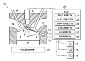
- FIG. 1 is a schematic diagram showing the structure of an engine to which a control device according to the present invention is applied;
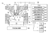
- FIG. 3 is a schematic diagram showing the structure of another engine to which the control device according to the present invention is applied;
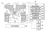
- FIG. 3 is a schematic diagram showing the structure of another engine to which the control device according to the present invention is applied;
- FIG. 3 is a schematic diagram showing the structure of another engine to which the control device according to the present invention is applied;
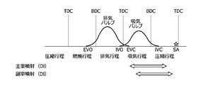
- FIG. 4 is a schematic diagram showing the timing of main chamber injection by port injection and the timing of sub chamber injection by in-cylinder injection;
- FIG. 4 is a schematic diagram showing the timing of main chamber injection and pre-chamber injection by in-cylinder injection.
- FIG. 4 is a schematic diagram showing the timing of main chamber injection and pre-chamber injection by port injection;
- FIG. 4 is a schematic diagram for explaining changes in mechanical compression ratio;
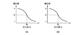
- (A) is a map showing the relationship between the pressure ratio R and the pre-chamber fuel amount correction value, and
- (B) is a map showing the relationship between the pressure difference D and the pre-chamber fuel amount correction value.
- (A) is a map for setting an additional correction value for the pre-chamber fuel amount
- (B) is a map for setting a first correction coefficient
- (C) is a map for setting a second correction coefficient.
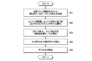
- is a map of 4 is a flowchart relating to control content (calculation of pressure ratio R). 4 is a flowchart relating to control content (fuel injection);
- FIG. 10 is a flowchart relating to control content (additional correction);
- [1. Constitution] 1 to 13 are diagrams for explaining a control device for an engine 10 (internal combustion engine) mounted on a vehicle.
- 1 to 4 schematically show the structure of a pre-combustion engine 10 in which a communicating main chamber 8 (main combustion chamber) and sub-combustion chamber 5 (sub-combustion chamber) are formed in a cylinder.
- . 1 and 2 show one of the methods (passive method) of supplying fuel from the injection valves (port injection valve 1, in-cylinder injection valve 3, multi-function injection valve 4) provided in the main chamber 8 and the intake port 11.
- 4 shows the structure of the engine 10 in which fuel is injected from the main chamber 8 toward the pre-chamber 5 to form a flame.
- FIG. 1 shows an injection valve (pre-chamber injection valve 2) for supplying fuel to the pre-chamber 5 and an injection valve (port injection valve 1, in-cylinder injection valve 3) for supplying fuel to the main chamber 8.
- the engine 10 is provided separately.
- FIG. 2 shows an engine 10 in which a single injection valve (multi-function injection valve 4) is used to blow fuel into the main chamber 8 and the auxiliary chamber 5 respectively.
- FIG. 3 shows the structure of the engine 10 of the type (active type) in which the fuel for forming the flame is directly supplied to the interior of the pre-chamber 5 .
- FIG. 4 shows an example of the structure of the engine 10 of a passive system, which is different from that shown in FIGS.
- the engine 10 includes a variable compression ratio mechanism 30.
- Variable compression ratio mechanism 30 is a mechanism for changing the mechanical compression ratio of engine 10 .
- the mechanical compression ratio can be adjusted, for example, by changing the stroke of the piston 31 inserted in the cylinder. Alternatively, it can be adjusted by changing the distance from the center of rotation of the crankshaft to the top surface of the piston 31 (the distance in the stroke direction).
- Various known structures can be applied to the specific structure of the variable compression ratio mechanism 30 (see Patent Document 1, for example).
- the control device for the engine 10 includes main chamber injection means for supplying fuel to the main chamber 8 and pre-chamber injection means for supplying fuel to the pre-chamber 5 .
- the auxiliary chamber 5 is formed, for example, in the shape of a hollow hemisphere protruding from the center of the top surface of the combustion chamber toward the piston 31 side. 1 to 4 show cases in which the pre-chamber 5 is arranged between the intake port 11 and the exhaust port 12 in a pent roof type cylinder head.
- the position of the pre-chamber 5 is preferably set in consideration of the overall shape of the combustion chamber, or in consideration of the operating ranges of the intake valve 13 and the exhaust valve 14 .
- the pre-chamber 5 may be arranged outside the cylinder (at a position closer to the cylindrical surface of the cylinder) than the intake port 11 and the exhaust port 12 .
- a minute hole 7 is formed in a partition wall 6 separating the sub-chamber 5 and the main chamber 8 .
- an electrode of a spark plug 9 is arranged inside the sub chamber 5 .
- the port injection valve 1 shown in FIGS. 1 and 3 is one of main chamber injection means, and is an injector that injects fuel into the intake port 11 .
- the direction of fuel injection by the port injection valve 1 is set, for example, toward the gap between the open intake valve 13 and the intake port 11 .
- the in-cylinder injection valve 3 is also one of the main chamber injection means, and is an injector that injects fuel into the main chamber 8 .
- the direction of fuel injection by the in-cylinder injection valve 3 is set, for example, according to the direction and flow velocity of airflow (tumble flow or swirl flow) formed in the combustion chamber during the compression stroke. Either one of the port injection valve 1 and the in-cylinder injection valve 3 can be omitted.
- the pre-chamber injection valve 2 shown in FIG. 1 is one of pre-chamber injection means, and is a passive injector that injects fuel into the pre-chamber 5 .
- the injection direction of the pre-chamber injection valve 2 is set, for example, toward the pre-chamber 5 .
- the injection direction of the pre-chamber injection valve 2 is not limited to the direction toward the pre-chamber 5 .
- the fuel may be injected toward a position slightly deviated from the pre-chamber 5 in consideration of the direction and velocity of the airflow (tumble flow or swirl flow) formed in the cylinder.
- the multi-function injection valve 4 shown in FIG. 2 is an injector having both the function of main chamber injection means and the function of pre-chamber injection means. At least two injection holes are formed at the tip of the multifunction injection valve 4 .
- One of the injection holes is an injection hole for realizing fuel injection similar to that of the in-cylinder injection valve 3 in FIG.
- the other injection hole is an injection hole for realizing fuel injection similar to that of the pre-chamber injection valve 2 in FIG.
- the open/closed state of each injection hole is individually controlled.
- the port injection valve 1 and the in-cylinder injection valve 3 shown in FIG. 4 are also injectors having both the function of the main chamber injection means and the function of the auxiliary chamber injection means. These port injection valve 1 and in-cylinder injection valve 3 have the function of blowing fuel separately into the main chamber 8 and sub chamber 5 by making injection timings different from each other.
- the fuel supply by the pre-chamber injection means is performed after the fuel supply by the main chamber injection means in one combustion cycle (a cycle consisting of four strokes of an intake stroke, a compression stroke, a combustion stroke, and an exhaust stroke).
- fuel supply by the main chamber injection means is carried out from the latter half of the exhaust stroke to the intake stroke.
- the fuel supply by the pre-chamber injection means is performed in the intake stroke and the compression stroke after the main chamber injection. Therefore, even if the main chamber injection and the sub chamber injection are performed by only a single injection valve, it is possible to clearly distinguish them based on the injection timing.
- the fuel injected from the main chamber injection means burns only in the main chamber 8, and some of the fuel may flow into the auxiliary chamber 5 as well.
- the fuel injected from the pre-chamber injection means burns only in the pre-chamber 5, and some of the fuel may flow out to the main chamber 8 as well.
- the fuel injected from the main chamber injection means is intended to burn in the main chamber 8, is injected at a timing that facilitates combustion in the main chamber 8, and most of it burns in the main chamber 8. .
- the fuel injected from the pre-chamber injection means is fuel intended to burn in the pre-chamber 5, is injected at a timing that facilitates combustion in the pre-chamber 5, and most of it burns in the pre-chamber 5.
- the main chamber injection means may be defined as "means for supplying fuel at timing suitable for combustion in the main chamber 8”
- the pre-chamber injection means may be defined as "means for supplying fuel at timing suitable for combustion in the pre-chamber 5". may be defined as "means for supplying fuel”.
- IVO and IVC indicate intake valve opening and intake valve closing respectively
- EVO and EVC indicate exhaust valve opening and closing of exhaust valve 14 respectively. Exhaust Valve Closing).
- TDC indicates Top Dead Center
- BDC indicates Bottom Dead Center.
- SA means ignition time (or crank angle corresponding to ignition timing, Spark Angle).
- FIG. 5 shows the timing of main chamber injection by port injection and the timing of pre-chamber injection by in-cylinder injection.
- the main chamber injection here includes, for example, fuel injection from the port injection valve 1 shown in FIGS.
- the main chamber injection by port injection can be performed not only while the intake valve 13 is open, but also during the previous exhaust stroke, combustion stroke, and compression stroke.
- the sub-chamber injection by in-cylinder injection is performed after the main chamber injection by port injection.
- the pre-chamber injection referred to here includes fuel injection from the pre-chamber injection valve 2 in FIG. 1 and the pre-chamber injection valve 2' in FIG.
- the pre-chamber injection by in-cylinder injection is performed during the period from EVC when the exhaust valve 14 is closed to SA when it is ignited.
- the number of injections for each of the main chamber injection and the sub chamber injection may be one or more.
- FIG. 6 shows the timing of main chamber injection and pre-chamber injection only by in-cylinder injection.
- the main chamber injection here includes, for example, fuel injection from the in-cylinder injection valve 3 in FIGS. 1, 3 and 4 and fuel injection from the multifunction injection valve 4 in FIG. 1, the multi-function injection valve 4 in FIG. 2, the pre-chamber injection valve 2' in FIG. 3, and the in-cylinder injection valve 3 in FIG. Includes fuel injection.
- Both of these main chamber injection and sub chamber injection are carried out during the period from EVC when the exhaust valve 14 is closed to SA when it is ignited.
- the auxiliary chamber injection is performed after the main chamber injection.
- the number of injections for each of the main chamber injection and the sub chamber injection may be one or more.
- FIG. 7 shows the timing of main chamber injection and pre-chamber injection by port injection only.
- the main chamber injection here includes, for example, fuel injection from the port injection valve 1 in FIG.
- Both the main chamber injection and the pre-chamber injection by port injection are performed during the period from the closing time IVC of the intake valve 13 in the previous combustion cycle to the closing time IVC of the intake valve 13 in the current combustion cycle.
- the auxiliary chamber injection is performed after the main chamber injection.
- the number of injections for each of the main chamber injection and the sub chamber injection may be one or more.
- a knock sensor 15, a cylinder pressure sensor 16, an engine speed sensor 17, an accelerator opening sensor 18, and a vehicle speed sensor 19 are provided in the engine 10 according to the present invention, as shown in FIGS.
- the knock sensor 15 is a sensor for detecting the presence or absence of knocking, which is a kind of abnormal combustion, and detects, for example, force, pressure, acceleration, etc. caused by cylinder vibration.
- the in-cylinder pressure sensor 16 is a sensor for grasping the combustion state in the combustion chamber, and detects the pressure in the main chamber 8 .
- the engine speed sensor 17 is a sensor for grasping the operating state of the engine 10, and detects, for example, the engine speed (angular velocity of the crankshaft) per unit time.
- the accelerator opening sensor 18 is a sensor for grasping the magnitude of the torque (driver requested torque) required for the engine 10, and detects the depression operation amount (accelerator opening) of an accelerator pedal (not shown).
- the vehicle speed sensor 19 is a sensor that detects the vehicle speed (running speed) of the vehicle in which the engine 10 is mounted. Various information detected by these sensors 15 to 19 is transmitted to the ECU 20 .
- the ECU 20 is an electronic control unit (Engine Control Unit, Electronic Control Unit) for controlling the operating state of the engine 10, and is an electronic device equipped with a processor and memory.
- the processor is, for example, a microprocessor such as a CPU (Central Processing Unit) or MPU (Micro Processing Unit), and the memory is, for example, ROM (Read Only Memory), RAM (Random Access Memory), non-volatile memory, or the like.
- the contents of the control performed by the ECU 20 are recorded and saved in the memory as firmware and application programs. When executing a program, the contents of the program are expanded in the memory space and executed by the processor.
- the ECU 20 is connected to each of the devices to be controlled and the sensors 15 to 19 via an in-vehicle network (not shown).
- devices to be controlled include a port injection valve 1, pre-chamber injection valves 2 and 2', an in-cylinder injection valve 3, a multifunction injection valve 4, and an ignition plug 9.
- FIG. 1 The fuel injection amount and ignition timing of the engine 10 and the operations of the intake valve 13 and the exhaust valve 14 are collectively managed by the ECU 20 . It is also possible to correct the fuel injection amount, ignition timing, mechanical compression ratio, etc. by using information detected by sensors not shown in FIGS. For example, the fuel injection amount and ignition timing may be corrected based on temperature information detected by an outside air temperature sensor, an engine cooling water temperature sensor, or the like.
- the ECU 20 is provided with in-cylinder pressure acquisition means 21, knocking detection means 22, combustion failure detection means 23, compression ratio control means 24, ignition control means 25, and fuel control means 26. These elements represent the functions realized by the ECU 20, and can be programmed as software recorded and stored in the ROM or auxiliary storage device within the ECU 20, for example. Alternatively, it may be realized as an electronic circuit (hardware) corresponding to the software, or as a system in which software and hardware coexist.
- the in-cylinder pressure obtaining means 21 obtains the value of the in-cylinder pressure (actually measured value or predicted value).
- the value of the in-cylinder pressure is acquired in a form associated with the crank angle in order to grasp the change in the in-cylinder pressure.
- the value of the in-cylinder pressure acquired here includes, for example, the in-cylinder pressure P1 at the time IVC when the intake valve 13 is closed, the in - cylinder pressure P2 at the time of ignition SA, and the like.
- a value detected by the in-cylinder pressure sensor 16 can be used as the measured value of the in-cylinder pressure.
- the predicted value of the in-cylinder pressure may be calculated, for example, based on the equation of state of gas.
- various conditions such as the specifications of the engine 10 and the components of the fuel mixture may be input into a known three-dimensional computational fluid analysis software, and the combustion state in the combustion chamber may be simulated for calculation.
- the value detected by the in-cylinder pressure sensor 16 at IVC when the intake valve 13 is closed is used as the in - cylinder pressure P1.
- the in-cylinder pressure P2 at the ignition time SA a value predicted based on the following equation 1 representing the adiabatic change of the combustion chamber is used.
- V1 in Equation 1 represents the combustion chamber volume at IVC when the intake valve 13 is closed
- V2 represents the combustion chamber volume at ignition SA.
- k is the known adiabatic index (Poisson index).
- the combustion chamber volumes V 1 and V 2 are calculated based on the operating state (mechanical compression ratio) of the variable compression ratio mechanism 30 and the crank angle at that time.
- the knocking detection means 22 detects knocking of the engine 10.
- whether or not knocking has occurred is determined based on information (values such as force, pressure, and acceleration generated by cylinder vibration) detected by the knock sensor 15, for example. In this case, it is determined that knocking has occurred, for example, when an acceleration greater than a predetermined acceleration is detected.
- knocking is detected. Presence or absence is determined. In this case, for example, when an angular velocity (angular acceleration greater than a predetermined angular acceleration) exceeding the angular acceleration range during normal operation is detected, it is determined that knocking has occurred.
- the combustion failure detection means 23 detects combustion failure of the engine 10 .
- the presence or absence of poor combustion is determined based on, for example, the in-cylinder pressure acquired by the in-cylinder pressure acquisition means 21 and the rotational fluctuation of the engine speed detected by the engine speed sensor 17 .
- the peak value of the in-cylinder pressure in the combustion stroke is extremely low, or when an angular velocity below the angular acceleration range during normal operation (angular velocity smaller than the second predetermined angular velocity) is detected, poor combustion occurs. It is judged that
- the compression ratio control means 24 controls the mechanical compression ratio of the engine 10 by controlling the variable compression ratio mechanism 30 .
- the operating state of the variable compression ratio mechanism 30 is controlled according to the operating state of the engine 10 .
- the target value of the mechanical compression ratio is set based on the engine load, engine cooling water temperature, engine speed, outside air temperature, etc., and the variable compression ratio mechanism 30 is controlled so that the actual mechanical compression ratio becomes the target value. is controlled.
- the engine load is calculated based on the accelerator opening and the vehicle speed.
- the ignition control means 25 controls the ignition timing of the spark plug 9 (the timing of igniting the fuel mixture).
- the ignition timing is set based on the engine load and engine speed.
- ignition control for retarding the ignition timing may be performed.
- the range of appropriate ignition timing is narrower than in other engines, and it is desired to suppress changes in ignition timing as much as possible. In consideration of such circumstances, the ignition retard control may not be performed even if knocking is detected.
- the ignition retard control may be started only when the time for which knocking is detected by the knocking detection means 22 exceeds a predetermined time.
- the fuel control means 26 controls the main chamber fuel amount, which is the fuel amount supplied by the main chamber injection means, and the pre-chamber fuel amount, which is the fuel amount supplied by the pre-chamber injection means. These fuel amounts are basically set based on the engine load and engine speed.
- the fuel control means 26 changes the pre-chamber fuel amount based on the mechanical compression ratio. For example, when the mechanical compression ratio is a high compression ratio with respect to a predetermined compression ratio, the pre-chamber fuel amount is decreased.
- the pre-chamber fuel amount is increased. Note that even when the ignition timing is changed from the standard state by the ignition control means 25, the actual compression ratio of the combustion chamber changes, so the pre-combustion chamber fuel amount may be changed based on the ignition timing.
- the fuel control means 26 as a parameter corresponding to the mechanical compression ratio of the combustion chamber, at least one of the pressure difference D and the pressure ratio R between the cylinder pressure P1 before compression and the cylinder pressure P2 after compression in the combustion chamber. is calculated.
- the values of the pressure difference D and the pressure ratio R are given by Equations 2 and 3 below.
- Values obtained by the in-cylinder pressure obtaining means 21 are used for the values of the in-cylinder pressures P 1 and P 2 in Equations 2 and 3. After that, based on the maps shown in FIGS. 9A and 9B, correction values for the pre-chamber fuel amount corresponding to the pressure difference D and the pressure ratio R are calculated.
- FIG. 9(A) is a map illustrating the relationship between the pressure ratio R and the pre-chamber fuel amount correction value
- FIG. 9(B) illustrates the relationship between the pressure difference D and the pre-chamber fuel amount correction value.
- the correction value for the pre-chamber fuel amount is set to a large value so that the pre-chamber fuel amount increases as the pressure ratio R and the pressure difference D decrease. That is, as the mechanical compression ratio decreases, the amount of fuel in the pre-chamber increases, and the torch flame in the pre-chamber 5 is strengthened. This ensures the stability of the combustion state.
- the pre-chamber fuel amount correction value is set not only to a positive value but also to a negative value.
- a negative correction value acts to reduce the pre-chamber fuel amount. By reducing the amount of fuel in the pre-chamber when the compression ratio is high, the torch flame in the pre-chamber 5 is weakened, and the occurrence of knocking and excessively steep combustion are suppressed.
- the pressure ratio R 0 and the pressure difference D 0 at which the correction value is 0 correspond to the values of the pressure ratio R and the pressure difference D calculated when the mechanical compression ratio and ignition timing are in the standard state.
- FIG. 10(A) is a map for setting an additional correction value for further correcting the correction value of the pre-chamber fuel amount.
- the additional correction value acts to further correct the pre-chamber fuel amount by being added to the correction value.
- the additional correction value is set based on the engine speed, and is set to a larger value as the engine speed increases, for example.
- the additional correction value is set such that the lower the mechanical compression ratio (the smaller the pressure ratio R and the pressure difference D), the greater the amount of increase in the pre-chamber fuel amount with respect to the increase in engine speed.
- the higher the engine speed the greater the amount of fuel in the pre-chamber, making it easier to secure the amount of fuel introduced into the pre-chamber 5 .
- FIGS. 10B and 10C are maps for setting first and second correction coefficients for further correcting the correction value of the pre-chamber fuel amount.
- the first and second correction coefficients act to further correct the pre-chamber fuel amount by being multiplied by the correction value.
- the first correction coefficient is set based on the in-cylinder pressure. Correction using the first correction coefficient is preferably performed when knocking of the engine 10 is detected by the knock detection means 22 or when combustion failure of the engine 10 is detected by the combustion failure detection means 23 . For example, when the in-cylinder pressure is so high as to exceed the normal fluctuation range, the higher the in-cylinder pressure, the smaller the first correction coefficient is set.
- the amount of fuel in the pre-chamber is reduced when the in-cylinder pressure is too high, making it easier to suppress the occurrence of knocking.
- the in-cylinder pressure is so low that it falls below the normal variation range, the lower the in-cylinder pressure, the larger the first correction coefficient is set.
- the amount of fuel in the pre-combustion chamber is increased when the in-cylinder pressure is too low, making it easier to eliminate poor combustion.
- the second correction coefficient is set based on the rotation fluctuation of the engine 10.
- the rotation fluctuation is given by, for example, the absolute value of the change gradient (angular acceleration) of the engine speed. Correction using the second correction coefficient is also preferably performed when knocking of the engine 10 is detected by the knock detection means 22 or when combustion failure of the engine 10 is detected by the combustion failure detection means 23 .
- the second correction coefficient is set to a smaller value as the rotational fluctuation increases. As a result, the amount of fuel in the pre-chamber is reduced when the rotation fluctuation is too large, and the occurrence of knocking can be easily suppressed.
- the pre-chamber fuel amount may be increased or decreased by controlling the pressure of the fuel supplied to the pre-chamber injection means or the injection pressure.
- fuel can be supplied in one combustion cycle by weakening or strengthening the injection force without changing the SOI (Start Of Injection) at the start of fuel injection or the EOI (End Of Injection) at the end of fuel injection.
- the pre-chamber fuel amount can be increased or decreased.
- the pre-chamber fuel amount may be increased or decreased by controlling the SOI at the start of fuel injection or the EOI at the end of fuel injection. In this case, by shortening or extending the fuel injection period while maintaining the pressure of the fuel supplied to the pre-chamber injection means and the injection pressure constant, the amount of fuel supplied to the pre-chamber in one combustion cycle is can be increased or decreased.
- the main chamber fuel amount may be set based on the engine load and the engine speed regardless of the magnitude of the correction value for the sub chamber fuel amount. Alternatively, the main chamber fuel amount may be increased (or decreased) by the same amount as the sub chamber fuel amount is decreased (or increased) so that the total fuel injection amount does not change.
- the standard main chamber fuel amount is denoted as F MAIN
- the standard sub chamber fuel amount is denoted as F SUB . If the decrease amount of the pre-chamber fuel amount is expressed as F DEC , the fuel amount actually injected from the pre-chamber injection means is F SUB -F DEC . At this time, the amount of fuel injected from the main chamber injection means may remain at F MAIN or may be set at F MAIN +F DEC .
- the amount of fuel injected from the main chamber injection means may be set within a range of F MAIN or more and F MAIN +F DEC or less.
- the amount of increase in the pre-chamber fuel amount is expressed as FINC
- the fuel amount actually injected from the pre-chamber injection means is F SUB + FINC .
- the amount of fuel injected from the main chamber injection means may remain at F MAIN or may be set at F MAIN -F INC .
- the amount of fuel injected from the main chamber injection means may be set within a range of F MAIN ⁇ F INC or more and F MAIN or less.
- FIG. 11 to 13 are flow charts for explaining the contents of the control performed by the ECU 20.
- FIG. Controls shown in these flow charts are executed independently of each other, and repeatedly executed in a predetermined cycle (for example, a cycle corresponding to one combustion cycle).
- FIG. 11 is a flow relating to calculation of the pressure ratio R.
- step A1 information on the in-cylinder pressure P 1 (actually measured value) and the crank angle ⁇ 1 at the IVC when the intake valve 13 is closed is obtained.
- the ignition timing SA is calculated based on the engine load and the engine speed, and the crank angle ⁇ 2 at the ignition timing SA is calculated.
- combustion chamber volumes V 1 and V 2 corresponding to the crank angles ⁇ 1 and ⁇ 2 are calculated based on the operating state of the variable compression ratio mechanism 30 .
- the in-cylinder pressure P 2 (predicted value) at the ignition timing SA is calculated based on, for example, Equation 1.
- the pressure ratio R is calculated based on Equation (3).
- the pressure ratio R calculated here is used in the flow shown in FIG. 12 to calculate the correction value for the pre-chamber fuel amount.
- the pressure difference D may be calculated based on, for example, Equation 2 in step A5.
- step A4 instead of calculating the in-cylinder pressure P 2 (predicted value) at the time of ignition SA, its actually measured value may be obtained. In this case, the information of the pressure ratio R calculated in step A5 is reflected in the correction value of the auxiliary chamber fuel amount in the next combustion cycle.
- FIG. 12 is a flow relating to fuel injection.
- step B1 a standard fuel amount for that combustion cycle is calculated based on the engine speed and engine load.
- the fuel amount the main chamber fuel amount and the sub chamber fuel amount are calculated separately.
- the auxiliary chamber fuel amount is calculated as a value smaller than the main chamber fuel amount.
- the pre-chamber fuel amount is about several percent to ten and several percent of the total fuel amount.
- step B2 a correction value for the pre-chamber fuel amount is calculated according to the pressure ratio R, for example, based on the map shown in FIG. 9(A).
- the pressure ratio R the lower the mechanical compression ratio
- the more the pre-chamber fuel amount is corrected to increase
- the larger the pressure ratio R the higher the mechanical compression ratio
- an additional correction value is calculated according to the engine speed.
- the additional correction value is calculated based on the map shown in FIG. 10(A).
- the higher the engine speed the larger the additional correction value calculated.
- the smaller the pressure ratio R the larger the additional correction value calculated.
- step B4 fuel injection is performed after the additional correction value is added to the correction value of the pre-chamber fuel amount calculated in step B2.
- the additional correction in step B3 may be omitted.
- FIG. 13 is a flow relating to additional correction for knocking and poor combustion of the engine 10 .
- step C1 it is determined whether or not the pre-chamber fuel amount has been changed in the flow shown in FIG.
- the difference between the standard pre-chamber fuel amount calculated in step B1 of FIG. 12 and the pre-chamber fuel amount actually supplied from the pre-chamber injection means in step B4 is calculated, and the absolute value of the difference is greater than or equal to a predetermined value. If this condition is satisfied, the process proceeds to step C2, and if not, the control in this control cycle ends.
- step C2 it is determined whether or not the knocking detection means 22 has detected knocking. If this condition is satisfied, the process proceeds to step C3, and correction is made to decrease the pre-chamber fuel amount.
- the first correction coefficient is set based on, for example, the in-cylinder pressure
- the second correction coefficient is set based on the rotational fluctuation.
- fuel injection is performed after the correction value of the pre-chamber fuel amount calculated in step B2 is multiplied by the first correction coefficient and the second correction coefficient.
- the first correction coefficient and the second correction coefficient set in step C3 are smaller than the normal values, and act to reduce the pre-chamber fuel amount in step C4.
- step C2 If the condition of step C2 is not met, the process proceeds to step C5, where it is determined whether or not the combustion failure detection means 23 has detected the combustion failure. If this condition is satisfied, the process proceeds to step C6, and correction is made to increase the pre-chamber fuel amount. On the other hand, if the condition of step C6 is not satisfied, the control in this control cycle ends.
- the first correction coefficient is set based on, for example, the in-cylinder pressure
- the second correction coefficient is set based on the rotational fluctuation.
- step C7 the correction value of the pre-chamber fuel amount calculated in step B2 is multiplied by the first correction coefficient and the second correction coefficient, and then fuel injection is carried out.
- the first correction coefficient and the second correction coefficient set in step C6 are larger than the normal values, and act to increase the pre-chamber fuel amount in step C7.
- the fuel control means 26 functions to control the pre-chamber fuel amount based on the mechanical compression ratio. That is, when the mechanical compression ratio is a high compression ratio, control is performed to reduce the pre-chamber fuel amount compared to when the mechanical compression ratio is a low compression ratio. As a result, the torch flame in the auxiliary chamber 5 can be weakened, and the occurrence of knocking can be suppressed. Also, when the mechanical compression ratio is a low compression ratio, control is performed to increase the pre-chamber fuel amount. As a result, the torch flame in the auxiliary chamber 5 can be strengthened, and the occurrence of poor combustion can be suppressed. Therefore, the stability of the combustion state of the engine 10 can be improved.
- the control device for the engine 10 described above is provided with an in-cylinder pressure obtaining means 21 for obtaining an actually measured value or a predicted value of the in-cylinder pressure. Further, the fuel control means 26 calculates the pre-chamber fuel amount based on the in-cylinder pressure at each of the intake valve closing time IVC and the ignition time SA. As a result, an appropriate pre-chamber fuel amount can be obtained with high accuracy, and the stability of the combustion state of the engine 10 can be further improved.
- the control device for the engine 10 is provided with knocking detection means 22 for detecting knocking. Further, the fuel control means 26 performs control to decrease the pre-chamber fuel amount when knocking is detected after changing the pre-chamber fuel amount based on the mechanical compression ratio. As a result, the occurrence of knocking can be suppressed more reliably, and the combustion state of the engine 10 can be stabilized. If only the sub chamber fuel amount is reduced while maintaining the main chamber fuel amount, the combustion state of the engine 10 can be easily improved without changing the control on the main chamber injection means side. Further, when the main chamber fuel amount is increased according to the amount of decrease in the pre-chamber fuel amount, the change in the total fuel amount can be reduced, and the combustion state of the engine 10 can be further stabilized.
- the control device for the engine 10 described above is provided with combustion failure detection means 23 for detecting combustion failure. Further, the fuel control means 26 performs control to increase the pre-combustion chamber fuel amount when poor combustion is detected after changing the pre-combustion chamber fuel amount based on the mechanical compression ratio. As a result, the occurrence of poor combustion can be suppressed more reliably, and the combustion state of the engine 10 can be stabilized. If only the sub chamber fuel amount is increased while maintaining the main chamber fuel amount, the combustion state of the engine 10 can be easily improved without changing the control on the main chamber injection means side. Further, when the main chamber fuel amount is decreased according to the increase in the pre-chamber fuel amount, the change in the total fuel amount can be reduced, and the combustion state of the engine 10 can be further stabilized.
- control device for the engine 10 mounted on the vehicle has been described in detail, but the application of the control device according to the present invention is not limited to the vehicle engine, and can be installed, for example, on a ship or a power generation facility. It is also applicable to engines that are The control device according to the present invention can be applied to an internal combustion engine having at least a main chamber injection means and a pre-chamber injection means.
- control for changing the pre-chamber fuel amount based on the valve timing may be added.
- the values of the pressure difference D and the pressure ratio R in the above embodiment reflect the valve timing control state. Therefore, it is possible to supply an appropriate amount of fuel to the pre-chamber according to changes in the actual compression ratio, and to optimize the force of the torch flame jetted from the pre-chamber 5 to the main chamber 8 .
Landscapes
- Engineering & Computer Science (AREA)
- Chemical & Material Sciences (AREA)
- Combustion & Propulsion (AREA)
- Mechanical Engineering (AREA)
- General Engineering & Computer Science (AREA)
- Electrical Control Of Air Or Fuel Supplied To Internal-Combustion Engine (AREA)
Abstract
本件のエンジンの制御装置は、機械的圧縮比を変更可能なエンジンの制御装置であり、主室(8)に燃料を供給する主室噴射手段(1,3)と、主室噴射手段(1,3)による燃料供給後に副室(5)に燃料を供給する副室噴射手段(2)とを備える。また、機械的圧縮比が高圧縮比の場合に、低圧縮比の場合と比較して、副室噴射手段(2)から供給される燃料量である副室燃料量を減少させる燃料制御手段(26)を備える。このような制御により、機械的圧縮比の高低にかかわらず、副室式エンジンの燃焼状態を安定させることができる。
Description
本件は、可変圧縮比機構を備えたエンジンの制御装置に関する。
従来、エンジンの機械的圧縮比を変更可能な可変圧縮比機構を搭載したエンジン(内燃機関)が知られている。このようなエンジンでは、エンジン回転数やエンジン負荷に応じてシリンダストロークを変更することができ、エンジンの作動状態に応じた最適な圧縮比を実現することができる(特許文献1参照)。
ところで、燃焼室内に主室(主燃焼室)と副室(副燃焼室)とを形成し、副室の内部に点火プラグの電極を配した副室式のエンジンが存在する。このようなエンジンでは、副室の内部で発生した火炎が、主室に向かってトーチ状に噴出するように形成される。一方、このようなエンジンで圧縮比を変更した場合に、燃焼状態が不安定化しやすいという課題がある。例えば、圧縮比の低下に伴いトーチ火炎が弱まり、燃焼不良になってしまうことがある。あるいは、圧縮比の上昇によってトーチ火炎が過大となり、燃焼が急峻になりすぎることもある。
本件の目的の一つは、上記のような課題に照らして創案されたものであり、機械的圧縮比の高低にかかわらず、副室式エンジンの燃焼状態を安定化することである。なお、この目的に限らず、後述する「発明を実施するための形態」に示す各構成から導き出される作用効果であって、従来の技術では得られない作用効果を奏することも、本件の他の目的として位置付けることができる。
本件のエンジンの制御装置は、機械的圧縮比を変更可能なエンジンの制御装置であって、主室に燃料を供給する主室噴射手段と、前記主室噴射手段による燃料供給後に副室に燃料を供給する副室噴射手段と、前記機械的圧縮比が高圧縮比の場合に、低圧縮比の場合と比較して、前記副室噴射手段から供給される燃料量である副室燃料量を減少させる燃料制御手段と、を備える。
本件のエンジンの制御装置によれば、機械的圧縮比の高低にかかわらず、副室式エンジンの燃焼状態を安定化できる。
[1.構成]
図1~図13は、車両に搭載されるエンジン10(内燃機関)の制御装置を説明するための図である。図1~図4はいずれも、連通する主室8(主燃焼室)及び副室5(副燃焼室)がシリンダ内に形成された副室式のエンジン10の構造を模式的に示している。図1,図2は、主室8や吸気ポート11に設けられた噴射弁(ポート噴射弁1,筒内噴射弁3,多機能噴射弁4)から燃料を供給する方式(パッシブ方式)のうち、火炎を形成するための燃料が主室8から副室5に向かって噴射される方式のエンジン10の構造を示す。図1は、副室5に燃料を供給するための噴射弁(副室噴射弁2)と主室8に燃料を供給するための噴射弁(ポート噴射弁1,筒内噴射弁3)とが別設されたエンジン10である。一方、図2は、単一の噴射弁(多機能噴射弁4)を用いて主室8と副室5とのそれぞれに燃料を吹き分けるエンジン10である。また、図3は、火炎を形成するための燃料が副室5の内部に直接的に供給される方式(アクティブ方式)のエンジン10の構造を示す。図4は、パッシブ方式のうち図1及び図2とは異なる方式のエンジン10の構造の一例を示す。
図1~図13は、車両に搭載されるエンジン10(内燃機関)の制御装置を説明するための図である。図1~図4はいずれも、連通する主室8(主燃焼室)及び副室5(副燃焼室)がシリンダ内に形成された副室式のエンジン10の構造を模式的に示している。図1,図2は、主室8や吸気ポート11に設けられた噴射弁(ポート噴射弁1,筒内噴射弁3,多機能噴射弁4)から燃料を供給する方式(パッシブ方式)のうち、火炎を形成するための燃料が主室8から副室5に向かって噴射される方式のエンジン10の構造を示す。図1は、副室5に燃料を供給するための噴射弁(副室噴射弁2)と主室8に燃料を供給するための噴射弁(ポート噴射弁1,筒内噴射弁3)とが別設されたエンジン10である。一方、図2は、単一の噴射弁(多機能噴射弁4)を用いて主室8と副室5とのそれぞれに燃料を吹き分けるエンジン10である。また、図3は、火炎を形成するための燃料が副室5の内部に直接的に供給される方式(アクティブ方式)のエンジン10の構造を示す。図4は、パッシブ方式のうち図1及び図2とは異なる方式のエンジン10の構造の一例を示す。
本件に係るエンジン10は、可変圧縮比機構30を備える。可変圧縮比機構30とは、エンジン10の機械的圧縮比を変更するための機構である。機械的圧縮比は、例えばシリンダに内挿されるピストン31のストロークを変化させることで調節可能である。あるいは、クランクシャフトの回転中心からピストン31の頂面までの距離(ストローク方向の距離)を変化させることで調節可能である。可変圧縮比機構30の具体的な構造については、公知の各種構造を適用することができる(例えば、特許文献1参照)。
本件に係るエンジン10の制御装置は、主室8に燃料を供給する主室噴射手段と、副室5に燃料を供給する副室噴射手段とを備える。図1~図4に示すように、副室5は、例えば燃焼室内の頂面中央部からピストン31側に向かって膨出した中空の半球状に形成される。図1~図4は、ペントルーフ型のシリンダヘッドにおいて、吸気ポート11と排気ポート12との間に副室5が配置された事例を示している。副室5の位置は、燃焼室の全体形状を考慮して、あるいは、吸気バルブ13や排気バルブ14の動作範囲を考慮して設定することが好ましい。また、吸気ポート11や排気ポート12よりもシリンダの外側(シリンダ筒面に近い位置)に副室5を配置してもよい。副室5と主室8とを隔てる隔壁6には、微小な孔7が形成される。また、副室5の内部には、点火プラグ9の電極が配置される。副室5の内部で燃料混合気が点火されると、その火炎が複数の孔7を介して副室5から主室8へとトーチ状に噴出するようになっている。
図1,図3に示すポート噴射弁1は、主室噴射手段の一つであって、吸気ポート11に燃料を噴射するインジェクタである。ポート噴射弁1による燃料の噴射方向は、例えば開放状態の吸気バルブ13と吸気ポート11との隙間に向かう方向に設定される。また、筒内噴射弁3も主室噴射手段の一つであって、主室8に燃料を噴射するインジェクタである。筒内噴射弁3による燃料の噴射方向は、例えば圧縮行程で燃焼室内に形成される気流(タンブル流やスワール流)の向きや流速に応じて設定される。ポート噴射弁1及び筒内噴射弁3のいずれか一方は省略可能である。
図1に示す副室噴射弁2は、副室噴射手段の一つであって、副室5に燃料を噴射するパッシブ型のインジェクタである。副室噴射弁2の噴射方向は、例えば副室5へ向かう方向に設定される。ただし、副室噴射弁2の噴射方向は、副室5へ向かう方向のみに限定されるわけではない。例えば、シリンダ内に形成される気流(タンブル流やスワール流)の向きや流速を考慮して、副室5からややずれた位置に向かって燃料を噴射させてもよい。また、図3に示す副室噴射弁2′も副室噴射手段の一つであり、副室5の内部に直接的に燃料を噴射するアクティブ型のインジェクタである。
図2に示す多機能噴射弁4は、主室噴射手段としての機能と副室噴射手段としての機能とを兼ね備えたインジェクタである。多機能噴射弁4の先端には、少なくとも二つの噴孔が形成される。一方の噴孔は、図1中の筒内噴射弁3と同様の燃料噴射を実現するための噴孔であって、主室8に供給される燃料が噴射される噴孔である。他方の噴孔は、図1中の副室噴射弁2と同様の燃料噴射を実現するための噴孔であって、副室5に供給される燃料が噴射される噴孔である。各々の噴孔の開閉状態は、個別に制御される。なお、図4に示すポート噴射弁1,筒内噴射弁3も、主室噴射手段としての機能と副室噴射手段としての機能とを兼ね備えたインジェクタである。これらのポート噴射弁1,筒内噴射弁3は、噴射時期を相違させることで、主室8と副室5とのそれぞれに燃料を吹き分ける機能を持つ。
副室噴射手段による燃料供給は、一つの燃焼サイクル(吸気行程,圧縮行程,燃焼行程,排気行程の四行程からなるサイクル)において、主室噴射手段による燃料供給の後に実施される。例えば、主室噴射手段による燃料供給は、排気行程後半から吸気行程にかけて実施される。これに対し、副室噴射手段による燃料供給は、主室噴射後の吸気行程や圧縮行程で実施される。したがって、単一の噴射弁のみで主室噴射と副室噴射が実施される場合であっても、噴射タイミングに基づいてそれらを明確に区別することが可能である。
なお、主室噴射手段から噴射される燃料の全てが主室8のみで燃焼するとは限らず、一部の燃料は副室5にも流入しうる。同様に、副室噴射手段から噴射される燃料の全てが副室5のみで燃焼するとは限らず、一部の燃料は主室8にも流出しうる。しかしながら、主室噴射手段から噴射される燃料は、主室8で燃焼することが意図された燃料であって、主室8で燃焼しやすいタイミングで噴射され、そのほとんどが主室8で燃焼する。同様に、副室噴射手段から噴射される燃料は、副室5で燃焼することが意図された燃料であって、副室5で燃焼しやすいタイミングで噴射され、そのほとんどが副室5で燃焼する。したがって、主室噴射手段を「主室8での燃焼に適したタイミングで燃料を供給する手段」と定義してもよいし、副室噴射手段を「副室5での燃焼に適したタイミングで燃料を供給する手段」と定義してもよい。
図5~図7は、主室噴射及び副室噴射のタイミングを説明するための模式図である。図中のIVO,IVCはそれぞれ吸気バルブ13の開放時(Intake Valve Opening),閉鎖時(Intake Valve Closing)を示し、EVO,EVCはそれぞれ排気バルブ14の開放時(Exhaust Valve Opening),閉鎖時(Exhaust Valve Closing)を示す。また、TDCは上死点(Top Dead Center)を示し、BDCは下死点(Bottom Dead Center)を示す。SAは点火時(あるいは点火時期に対応するクランク角,Spark Angle)を意味する。
図5は、ポート噴射による主室噴射のタイミングと、筒内噴射による副室噴射のタイミングとを示す。ここでいう主室噴射には、例えば図1,図3のポート噴射弁1からの燃料噴射が含まれる。ポート噴射による主室噴射は、吸気バルブ13の開放中だけでなく、それ以前の排気行程や燃焼行程や圧縮行程でも実施されうる。一方、筒内噴射による副室噴射は、ポート噴射による主室噴射よりも後に実施される。ここでいう副室噴射には、図1の副室噴射弁2や図3の副室噴射弁2′からの燃料噴射が含まれる。筒内噴射による副室噴射は、排気バルブ14の閉鎖時EVCから点火時SAまでの期間に実施される。主室噴射,副室噴射の各々の噴射回数は、一回でもよいし複数回でもよい。
図6は、筒内噴射のみによる主室噴射及び副室噴射のタイミングを示す。ここでいう主室噴射には、例えば図1,図3,図4の筒内噴射弁3からの燃料噴射や図2の多機能噴射弁4からの燃料噴射が含まれる。また、ここでいう副室噴射には、例えば図1の副室噴射弁2,図2の多機能噴射弁4,図3の副室噴射弁2′,図4の筒内噴射弁3からの燃料噴射が含まれる。これらの主室噴射及び副室噴射は、ともに排気バルブ14の閉鎖時EVCから点火時SAまでの期間に実施される。また、副室噴射は、主室噴射よりも後に実施される。主室噴射,副室噴射の各々の噴射回数は、一回でもよいし複数回でもよい。
図7は、ポート噴射のみによる主室噴射及び副室噴射のタイミングを示す。ここでいう主室噴射には、例えば図4のポート噴射弁1からの燃料噴射が含まれる。ポート噴射による主室噴射及び副室噴射は、ともに前回の燃焼サイクルにおける吸気バルブ13の閉鎖時IVCから今回の燃焼サイクルにおける吸気バルブ13の閉鎖時IVCまでの期間に実施される。また、副室噴射は、主室噴射よりも後に実施される。主室噴射,副室噴射の各々の噴射回数は、一回でもよいし複数回でもよい。
本件に係るエンジン10には、図1~図4に示すように、ノックセンサ15,筒内圧センサ16,エンジン回転数センサ17,アクセル開度センサ18,車速センサ19が設けられる。ノックセンサ15は、異常燃焼の一種であるノッキングの有無を把握するためのセンサであり、例えばシリンダの振動によって生じる力,圧力,加速度などを検出する。筒内圧センサ16は、燃焼室内における燃焼状態を把握するためのセンサであり、主室8の圧力を検出する。エンジン回転数センサ17は、エンジン10の作動状態を把握するためのセンサであり、例えば単位時間あたりのエンジン回転数(クランクシャフトの角速度)を検出する。アクセル開度センサ18は、エンジン10に要求されるトルク(ドライバ要求トルク)の大きさを把握するためのセンサであり、図示しないアクセルペダルの踏み込み操作量(アクセル開度)を検出する。車速センサ19は、エンジン10が搭載された車両の車速(走行速度)を検出するセンサである。これらのセンサ15~19で検出された各種情報は、ECU20に伝達される。
ECU20は、エンジン10の作動状態を制御するための電子制御装置(Engine Control Unit, Electronic Control Unit)であって、プロセッサとメモリとを搭載した電子デバイスである。プロセッサは、例えばCPU(Central Processing Unit),MPU(Micro Processing Unit)などのマイクロプロセッサであり、メモリは、例えばROM(Read Only Memory),RAM(Random Access Memory),不揮発メモリなどである。ECU20で実施される制御の内容は、ファームウェアやアプリケーションプログラムとしてメモリに記録,保存される。プログラムの実行時には、プログラムの内容がメモリ空間内に展開され、プロセッサによって実行される。
ECU20は、図示しない車載ネットワークを介して、制御対象となる装置及びセンサ15~19の各々に接続される。図1~図4に示すように、制御対象となる装置にはポート噴射弁1,副室噴射弁2,2′,筒内噴射弁3,多機能噴射弁4,点火プラグ9が含まれる。エンジン10の燃料噴射量や点火時期,吸気バルブ13及び排気バルブ14の動作は、ECU20によって統括的に管理される。なお、図1~図4に示されていないセンサで検出された情報を併用して、燃料噴射量,点火時期,機械的圧縮比等を補正することも可能である。例えば、外気温センサやエンジン冷却水温センサなどで検出された温度情報に基づき、燃料噴射量や点火時期を補正してもよい。
ECU20には、筒内圧取得手段21,ノッキング検出手段22,燃焼不良検出手段23,圧縮比制御手段24,点火制御手段25,燃料制御手段26が設けられる。これらの要素は、ECU20で実現される機能を表現したものであり、例えばECU20内のROMや補助記憶装置に記録,保存されるソフトウェアとしてプログラミングされうる。あるいは、そのソフトウェアに対応する電子回路(ハードウェア)として実現されてもよいし、ソフトウェアとハードウェアとが混在するシステムとして実現されてもよい。
筒内圧取得手段21は、筒内圧の値(実測値または予測値)を取得するものである。ここでは、筒内圧の変化を把握すべく、筒内圧の値がクランク角に対応付けられた形で取得される。ここで取得される筒内圧の値には、例えば吸気バルブ13の閉鎖時IVCにおける筒内圧P1や、点火時SAにおける筒内圧P2などが含まれる。なお、筒内圧の実測値としては、筒内圧センサ16で検出された値を用いることができる。また、筒内圧の予測値は、例えば気体の状態方程式に基づいて算出してもよい。あるいは、公知の三次元数値流体解析ソフトウェアにエンジン10の諸元や燃料混合気の成分といった諸条件を入力し、燃焼室内での燃焼状態をシミュレートすることで算出してもよい。
本実施例では、吸気バルブ13の閉鎖時IVCに筒内圧センサ16で検出された値が筒内圧P1として用いられる。また、点火時SAにおける筒内圧P2は、燃焼室の断熱変化を表す以下の式1に基づいて予測される値が用いられる。図8に示すように、式1中のV1は吸気バルブ13の閉鎖時IVCにおける燃焼室体積を表し、V2は点火時SAにおける燃焼室体積を表す。kは、既知の断熱指数(ポアソン指数)である。燃焼室体積V1,V2は、可変圧縮比機構30の作動状態(機械的圧縮比)とそのときのクランク角とに基づいて算出される。

ノッキング検出手段22は、エンジン10のノッキングを検出するものである。ここでは、例えばノックセンサ15で検出された情報(シリンダ振動によって生じる力,圧力,加速度などの値)に基づいて、ノッキングが発生したか否かが判断される。この場合、例えば所定加速度よりも大きな加速度を検知した場合に、ノッキングが発生したと判断される。あるいは、筒内圧取得手段21で取得された筒内圧やエンジン回転数センサ17で検出されたエンジン回転数の回転変動〔エンジン回転数の変化勾配(角加速度)の絶対値〕に基づいて、ノッキングの有無が判断される。この場合、例えば通常運転時の角加速度範囲を超える角速度(所定角加速度よりも大きな角加速度)を検知した場合に、ノッキングが発生したと判断される。
燃焼不良検出手段23は、エンジン10の燃焼不良を検出するものである。ここでは、例えば筒内圧取得手段21で取得された筒内圧やエンジン回転数センサ17で検出されたエンジン回転数の回転変動に基づいて、燃焼不良の有無が判断される。具体的には、例えば燃焼行程における筒内圧のピーク値が著しく低い場合や、通常運転時の角加速度範囲を下回る角速度(第2所定角速度よりも小さな角速度)を検知した場合に、燃焼不良が発生したと判断される。
圧縮比制御手段24は、可変圧縮比機構30を制御してエンジン10の機械的圧縮比を制御するものである。ここでは、エンジン10の作動状態に応じて、可変圧縮比機構30の作動状態が制御される。例えば、エンジン負荷やエンジン冷却水温,エンジン回転数,外気温などに基づいて機械的圧縮比の目標値が設定され、実際の機械的圧縮比がその目標値のなるように、可変圧縮比機構30が制御される。なお、エンジン負荷は、アクセル開度と車速とに基づいて算出される。
点火制御手段25は、点火プラグ9の点火時期(燃料混合気を点火するタイミング)を制御するものである。点火時期は、エンジン負荷とエンジン回転数とに基づいて設定される。一方、ノッキング検出手段22でノッキングが検出された場合には、点火時期をリタードさせる点火制御を実施してもよい。ただし、副室式エンジンにおいては、適切な点火時期の範囲が他のエンジンと比較して狭く、点火時期の変化をできるだけ抑制することが望まれる。このような実情を踏まえて、ノッキングが検出されたとしても点火リタード制御を実施しないこととしてもよい。あるいは、ノッキング検出手段22でノッキングが検出された時間が所定時間を超えた場合に限って、点火リタード制御を開始することとしてもよい。
燃料制御手段26は、主室噴射手段が供給する燃料量である主室燃料量と、副室噴射手段が供給する燃料量である副室燃料量とを制御するものである。これらの燃料量は、基本的にはエンジン負荷とエンジン回転数とに基づいて設定される。一方、圧縮比制御手段24によって機械的圧縮比が標準状態から変更されている場合には、副室5から主室8に噴出されるトーチ火炎の勢いが変動しうる。そこで、本件の燃料制御手段26は、機械的圧縮比に基づいて副室燃料量を変更する。例えば、機械的圧縮比が所定圧縮比を基準として高圧縮比である場合に、副室燃料量を減少させる。反対に、所定圧縮比を基準として低圧縮比である場合には、副室燃料量を増加させる。なお、点火制御手段25によって点火時期が標準状態から変更されている場合にも、燃焼室の実圧縮比が変化するため、点火時期に基づいて副室燃料量を変更してもよい。
燃料制御手段26では、燃焼室の機械的圧縮比に相当するパラメータとして、燃焼室内における圧縮前の筒内圧P1と圧縮後の筒内圧P2との圧力差D,圧力比Rの少なくともいずれかが算出される。圧力差D,圧力比Rの値は、以下の式2,式3で与えられる。式2,式3中の筒内圧P1,P2の値には、筒内圧取得手段21で取得された値が用いられる。その後、図9(A),(B)に示すようなマップに基づき、圧力差D,圧力比Rに応じた副室燃料量の補正値が算出される。
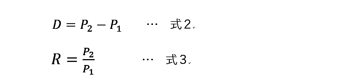
図9(A)は圧力比Rと副室燃料量の補正値との関係を例示するマップであり、図9(B)は圧力差Dと副室燃料量の補正値との関係を例示するマップである。副室燃料量の補正値は、圧力比R,圧力差Dが小さいほど、副室燃料量が増加するように大きな値に設定される。つまり、機械的圧縮比が低下するにつれて副室燃料量が増量され、副室5のトーチ火炎が強化される。これにより、燃焼状態の安定性が確保される。
また、圧力比R,圧力差Dが大きいほど、補正値が小さな値に設定される。副室燃料量の補正値がとりうる範囲は、正の範囲のみであってもよいし、負の範囲まで拡張されてもよい。図9(A),(B)では、副室燃料量の補正値が正の値だけでなく負の値にも設定されている。負の補正値は、副室燃料量を減少補正するように作用する。圧縮比が高い状態での副室燃料量を減少させることで、副室5のトーチ火炎が弱められ、ノッキングの発生や燃焼が急峻になりすぎることが抑制される。なお、補正値が0となる圧力比R0,圧力差D0は、機械的圧縮比や点火時期が標準状態であるときに算出される圧力比R,圧力差Dの値に相当する。
図10(A)は、上記の副室燃料量の補正値をさらに補正する追加補正値を設定するためのマップである。追加補正値は、補正値に加算されることで副室燃料量をさらに補正するように作用する。追加補正値は、エンジン回転数に基づいて設定され、例えばエンジン回転数が高いほど大きな値に設定される。また、追加補正値は、機械的圧縮比が低いほど(圧力比Rや圧力差Dが小さいほど)、エンジン回転数の増加に対する副室燃料量の増加量が大きくなるように設定される。これにより、エンジン回転数が高いほど副室燃料量が増量され、副室5に導入される燃料量が確保されやすくなる。ただし、燃料が副室5の内部に直接的に供給されるアクティブ方式のエンジン10である場合を除く。
図10(B),(C)は、副室燃料量の補正値をさらに補正する第1,第2補正係数を設定するためのマップである。第1,第2補正係数は、補正値に乗算されることで副室燃料量をさらに補正するように作用する。
第1補正係数は、筒内圧に基づいて設定される。第1補正係数による補正は、ノッキング検出手段22でエンジン10のノッキングが検出された場合や、燃焼不良検出手段23でエンジン10の燃焼不良が検出された場合に実施することが好ましい。第1補正係数は、例えば筒内圧が通常の変動範囲を超えるほど高い場合に、その筒内圧が高いほど小さな値に設定される。これにより、筒内圧が高すぎる状況下での副室燃料量が減量され、ノッキングの発生が抑制されやすくなる。また、筒内圧が通常の変動範囲を下回るほど低い場合には、その筒内圧が低いほど第1補正係数が大きな値に設定される。これにより、筒内圧が低すぎる状況下での副室燃料量が増量され、燃焼不良が解消されやすくなる。
第1補正係数は、筒内圧に基づいて設定される。第1補正係数による補正は、ノッキング検出手段22でエンジン10のノッキングが検出された場合や、燃焼不良検出手段23でエンジン10の燃焼不良が検出された場合に実施することが好ましい。第1補正係数は、例えば筒内圧が通常の変動範囲を超えるほど高い場合に、その筒内圧が高いほど小さな値に設定される。これにより、筒内圧が高すぎる状況下での副室燃料量が減量され、ノッキングの発生が抑制されやすくなる。また、筒内圧が通常の変動範囲を下回るほど低い場合には、その筒内圧が低いほど第1補正係数が大きな値に設定される。これにより、筒内圧が低すぎる状況下での副室燃料量が増量され、燃焼不良が解消されやすくなる。
第2補正係数はエンジン10の回転変動に基づいて設定される。回転変動は、例えばエンジン回転数の変化勾配(角加速度)の絶対値で与えられる。第2補正係数による補正も、ノッキング検出手段22でエンジン10のノッキングが検出された場合や、燃焼不良検出手段23でエンジン10の燃焼不良が検出された場合に実施することが好ましい。第2補正係数は、例えば回転変動が通常の変動範囲を超えるほど高い場合に、その回転変動が大きいほど小さな値に設定される。これにより、回転変動が大きすぎる状況下での副室燃料量が減量され、ノッキングの発生が抑制されやすくなる。また、回転変動が通常の変動範囲を下回るほど低い場合には、その回転変動が小さいほど第2補正係数が大きな値に設定される。これにより、回転変動が小さすぎる状況下での副室燃料量が増量され、燃焼不良が解消されやすくなる。
副室燃料量は、副室噴射手段に供給される燃料の圧力や噴射圧をコントロールすることで増減させてもよい。この場合、燃料噴射開始時SOI(Start Of Injection)や燃料噴射終了時EOI(End Of Injection)を変更することなく噴射の勢いを弱めたり強めたりすることで、一回の燃焼サイクルで供給される副室燃料量を増減させることができる。あるいは、燃料噴射開始時SOIや燃料噴射終了時EOIをコントロールすることで副室燃料量を増減させてもよい。この場合、副室噴射手段に供給される燃料の圧力や噴射圧を一定に保ちつつ、燃料噴射期間を短縮したり延長したりすることで、一回の燃焼サイクルで供給される副室燃料量を増減させることができる。
主室燃料量は、副室燃料量の補正値の大小に関わらず、エンジン負荷とエンジン回転数とに基づいて設定されることにしてもよい。あるいは、トータルの燃料噴射量が変化しないように、副室燃料量を減少(または増加)させた分だけ主室燃料量を増加(または減少)させてもよい。ここで、標準的な主室燃料量をFMAINと表記し、標準的な副室燃料量をFSUBと表記する。副室燃料量の減少量をFDECと表記すれば、実際に副室噴射手段から噴射される燃料量はFSUB-FDECとなる。このとき、主室噴射手段から噴射される燃料量はFMAINのままにしてもよいし、FMAIN+FDECとしてもよい。あるいは、FMAIN以上かつFMAIN+FDEC以下の範囲内で、主室噴射手段から噴射される燃料量を設定してもよい。同様に、副室燃料量の増加量をFINCと表記すれば、実際に副室噴射手段から噴射される燃料量はFSUB+FINCとなる。このとき、主室噴射手段から噴射される燃料量はFMAINのままにしてもよいし、FMAIN-FINCとしてもよい。あるいは、FMAIN-FINC以上かつFMAIN以下の範囲内で、主室噴射手段から噴射される燃料量を設定してもよい。
[2.フローチャート]
図11~図13は、ECU20で実施される制御の内容を説明するためのフローチャートである。これらのフローチャートに示される制御は互いに独立して実行され、所定の周期(例えば、一回の燃焼サイクルに対応する周期)で繰り返し実行される。
図11は、圧力比Rの算出に係るフローである。ステップA1では、吸気バルブ13の閉鎖時IVCにおける筒内圧P1(実測値)及びクランク角θ1の情報が取得される。ステップA2では、エンジン負荷とエンジン回転数とに基づいて点火時SAが算出され、その点火時SAにおけるクランク角θ2が算出される。ステップA3では、可変圧縮比機構30の作動状態に基づき、クランク角θ1,θ2に対応する燃焼室体積V1,V2が算出される。ステップA4では、例えば式1に基づき、点火時SAの筒内圧P2(予測値)が算出される。
図11~図13は、ECU20で実施される制御の内容を説明するためのフローチャートである。これらのフローチャートに示される制御は互いに独立して実行され、所定の周期(例えば、一回の燃焼サイクルに対応する周期)で繰り返し実行される。
図11は、圧力比Rの算出に係るフローである。ステップA1では、吸気バルブ13の閉鎖時IVCにおける筒内圧P1(実測値)及びクランク角θ1の情報が取得される。ステップA2では、エンジン負荷とエンジン回転数とに基づいて点火時SAが算出され、その点火時SAにおけるクランク角θ2が算出される。ステップA3では、可変圧縮比機構30の作動状態に基づき、クランク角θ1,θ2に対応する燃焼室体積V1,V2が算出される。ステップA4では、例えば式1に基づき、点火時SAの筒内圧P2(予測値)が算出される。
ステップA5では、式3に基づき、圧力比Rが算出される。ここで算出された圧力比Rは、図12に示すフローにおいて、副室燃料量の補正値を算出するために用いられる。なお、圧力比Rの代わりに圧力差Dを用いて副室燃料量の補正値を算出する場合には、ステップA5において、例えば式2に基づいて圧力差Dを算出すればよい。また、ステップA4において、点火時SAの筒内圧P2(予測値)を算出する代わりに、その実測値を取得するようにしてもよい。この場合、ステップA5で算出された圧力比Rの情報は、次回の燃焼サイクルにおける副室燃料量の補正値に反映される。
図12は、燃料噴射に係るフローである。ステップB1では、エンジン回転数及びエンジン負荷に基づき、その燃焼サイクルでの標準的な燃料量が算出される。燃料量は、主室燃料量と副室燃料量とが個別に算出される。本件では、副室燃料量が主室燃料量よりも少ない値として算出される。例えば、副室燃料量が燃料量全体に対して数パーセントから十数パーセント程度とされる。ステップB2では、例えば図9(A)に示すマップに基づき、圧力比Rに応じて副室燃料量の補正値が算出される。ここでは、圧力比Rが小さいほど(機械的圧縮比が低いほど)副室燃料量が増加補正され、圧力比Rが大きいほど(機械的圧縮比が高いほど)副室燃料量が減少補正される。
ステップB3では、エンジン回転数に応じて追加補正値が算出される。例えば、図10(A)に示すマップに基づいて追加補正値が算出される。ここでは、エンジン回転数が高いほど追加補正値が大きな値に算出される。また、圧力比Rが小さいほど追加補正値が大きな値に算出される。これにより、エンジン回転数が高く、機械的圧縮比が低いほど副室燃料量が増量され、副室5に導入される燃料量が確保されやすくなる。そしてステップB4では、ステップB2で算出された副室燃料量の補正値に追加補正値が加算された後、燃料噴射が実施される。なお、燃料が副室5の内部に直接的に供給されるアクティブ方式のエンジン10においては、ステップB3の追加補正を省略してもよい。
図13は、エンジン10のノッキングや燃焼不良に対する追加補正に係るフローである。ステップC1では図12に示すフローにおいて副室燃料量が変更されているか否かが判定される。ここでは、例えば図12のステップB1で算出された標準的な副室燃料量とステップB4で副室噴射手段から実際に供給された副室燃料量との差が算出され、その差の絶対値が所定値以上であるか否かが判定される。この条件が成立する場合にはステップC2に進み、成立しない場合にはこの制御サイクルでの制御が終了する。
ステップC2では、ノッキング検出手段22でノッキングが検出されているか否かが判定される。この条件が成立している場合にはステップC3に進み、副室燃料量を減少させる補正がなされる。ステップC3では、例えば筒内圧に基づいて第1補正係数が設定されるとともに、回転変動に基づいて第2補正係数が設定される。その後のステップC4では、ステップB2で算出された副室燃料量の補正値に第1補正係数,第2補正係数が乗算された後、燃料噴射が実施される。ノッキングが発生している状況下では、筒内圧や回転変動が通常の変動範囲を超えるほど高くなる。したがって、ステップC3で設定される第1補正係数,第2補正係数は通常時よりも小さい値となり、ステップC4において副室燃料量を減少させるように作用する。
ステップC2の条件が不成立の場合にはステップC5に進み、燃焼不良検出手段23で燃焼不良が検出されているか否かが判定される。この条件が成立している場合にはステップC6に進み、副室燃料量を増加させる補正がなされる。一方、ステップC6の条件が成立しない場合には、この制御サイクルでの制御が終了する。
ステップC6では、例えば筒内圧に基づいて第1補正係数が設定されるとともに、回転変動に基づいて第2補正係数が設定される。その後のステップC7では、ステップB2で算出された副室燃料量の補正値に第1補正係数,第2補正係数が乗算された後、燃料噴射が実施される。なお、燃焼不良が発生している状況下では、筒内圧や回転変動が通常の変動範囲を下回る程度まで低下する。したがって、ステップC6で設定される第1補正係数,第2補正係数は通常時よりも大きな値となり、ステップC7において副室燃料量を増加させるように作用する。
ステップC6では、例えば筒内圧に基づいて第1補正係数が設定されるとともに、回転変動に基づいて第2補正係数が設定される。その後のステップC7では、ステップB2で算出された副室燃料量の補正値に第1補正係数,第2補正係数が乗算された後、燃料噴射が実施される。なお、燃焼不良が発生している状況下では、筒内圧や回転変動が通常の変動範囲を下回る程度まで低下する。したがって、ステップC6で設定される第1補正係数,第2補正係数は通常時よりも大きな値となり、ステップC7において副室燃料量を増加させるように作用する。
[3.作用,効果]
(1)上記のエンジン10の制御装置(すなわちECU20)では、燃料制御手段26の働きにより、機械的圧縮比に基づいて副室燃料量が制御される。すなわち、機械的圧縮比が高圧縮比の場合には、低圧縮比の場合と比較して、副室燃料量を減少させる制御が実施される。これにより、副室5のトーチ火炎を弱めることができ、ノッキングの発生を抑制することができる。また、機械的圧縮比が低圧縮比の場合には、副室燃料量を増加させる制御が実施される。これにより、副室5のトーチ火炎を強めることができ、燃焼不良の発生を抑制することができる。したがって、エンジン10の燃焼状態の安定性を向上させることができる。
(1)上記のエンジン10の制御装置(すなわちECU20)では、燃料制御手段26の働きにより、機械的圧縮比に基づいて副室燃料量が制御される。すなわち、機械的圧縮比が高圧縮比の場合には、低圧縮比の場合と比較して、副室燃料量を減少させる制御が実施される。これにより、副室5のトーチ火炎を弱めることができ、ノッキングの発生を抑制することができる。また、機械的圧縮比が低圧縮比の場合には、副室燃料量を増加させる制御が実施される。これにより、副室5のトーチ火炎を強めることができ、燃焼不良の発生を抑制することができる。したがって、エンジン10の燃焼状態の安定性を向上させることができる。
(2)上記のエンジン10の制御装置では、エンジン回転数が高いほど燃料制御手段26が追加補正値を大きな値に設定し、副室燃料量を増加させる制御を実施する。また、機械的圧縮比が低いほど、エンジン回転数の増加に対する追加補正値の増加量(増加率)が大きく設定される。これにより、パッシブ方式のエンジン10において、高回転領域で副室5に導入される燃料量の減少を抑えることができる。したがって、エンジン10の燃焼状態の安定性をさらに向上させることができる。
(3)上記のエンジン10の制御装置には、筒内圧の実測値または予測値を取得する筒内圧取得手段21が設けられる。また、燃料制御手段26は、吸気バルブ閉鎖時IVC及び点火時SAの各々における筒内圧に基づいて副室燃料量を算出する。これにより、適切な量の副室燃料量を精度よく求めることができ、エンジン10の燃焼状態の安定性をさらに向上させることができる。
(4)上記のエンジン10の制御装置には、ノッキングを検出するノッキング検出手段22が設けられる。また、燃料制御手段26は、機械的圧縮比に基づいて副室燃料量を変更した後に、ノッキングが検出された場合に、副室燃料量を減少させる制御を実施する。これにより、ノッキングの発生をより確実に抑制でき、エンジン10の燃焼状態を安定させることができる。なお、主室燃料量を保ったまま副室燃料量のみを減少させた場合には、主室噴射手段側の制御を変更することなく容易にエンジン10の燃焼状態を改善することができる。また、副室燃料量の減少量に応じて主室燃料量を増加させた場合には、トータルの燃料量の変化を小さくすることができ、エンジン10の燃焼状態をさらに安定させることができる。
(5)上記のエンジン10の制御装置には、燃焼不良を検出する燃焼不良検出手段23が設けられる。また、燃料制御手段26は、機械的圧縮比に基づいて副室燃料量を変更した後に、燃焼不良が検出された場合に、副室燃料量を増加させる制御を実施する。これにより、燃焼不良の発生をより確実に抑制でき、エンジン10の燃焼状態を安定させることができる。なお、主室燃料量を保ったまま副室燃料量のみを増加させた場合には、主室噴射手段側の制御を変更することなく容易にエンジン10の燃焼状態を改善することができる。また、副室燃料量の増加量に応じて主室燃料量を減少させた場合には、トータルの燃料量の変化を小さくすることができ、エンジン10の燃焼状態をさらに安定させることができる。
[4.変形例]
上記の実施例はあくまでも例示に過ぎず、本実施例で明示しない種々の変形や技術の適用を排除する意図はない。本実施例の各構成は、それらの趣旨を逸脱しない範囲で種々変形して実施できる。また、本実施例の各構成は、必要に応じて取捨選択でき、あるいは適宜組み合わせることができる。例えば、上記の実施例では車両に搭載されるエンジン10の制御装置について詳述したが、本件に係る制御装置の適用対象は車載エンジンのみに制限されることはなく、例えば船舶や発電施設に設置されるエンジンにも適用可能である。少なくとも、主室噴射手段と副室噴射手段とを備えた内燃機関であれば、本件に係る制御装置を適用することが可能である。
上記の実施例はあくまでも例示に過ぎず、本実施例で明示しない種々の変形や技術の適用を排除する意図はない。本実施例の各構成は、それらの趣旨を逸脱しない範囲で種々変形して実施できる。また、本実施例の各構成は、必要に応じて取捨選択でき、あるいは適宜組み合わせることができる。例えば、上記の実施例では車両に搭載されるエンジン10の制御装置について詳述したが、本件に係る制御装置の適用対象は車載エンジンのみに制限されることはなく、例えば船舶や発電施設に設置されるエンジンにも適用可能である。少なくとも、主室噴射手段と副室噴射手段とを備えた内燃機関であれば、本件に係る制御装置を適用することが可能である。
なお、吸気バルブ13及び排気バルブ14のバルブタイミングやバルブリフト量を変更する可変バルブ機構を備えたエンジンにおいて、バルブタイミングに基づいて副室燃料量を変更する制御を付加してもよい。上記の実施例における圧力差Dや圧力比Rの値には、バルブタイミングの制御状態が反映される。したがって、実圧縮比の変化に応じた適量の副室燃料量を供給することができ、副室5から主室8に噴出されるトーチ火炎の勢いを適正化することができる。
1 ポート噴射弁(主室噴射手段)
2,2′ 副室噴射弁(副室噴射手段)
3 筒内噴射弁(主室噴射手段)
4 多機能噴射弁(主室噴射手段,副室噴射手段)
5 副室
6 隔壁
7 孔
8 主室
9 点火プラグ
10 エンジン
11 吸気ポート
12 排気ポート
13 吸気バルブ
14 排気バルブ
15 ノックセンサ
16 筒内圧センサ
17 エンジン回転数センサ
18 アクセル開度センサ
19 車速センサ
20 ECU
21 筒内圧取得手段
22 ノッキング検出手段
23 燃焼不良検出手段
24 圧縮比制御手段
25 点火制御手段
26 燃料制御手段
30 可変圧縮比機構
31 ピストン
IVO 吸気バルブ13の開放時
IVC 吸気バルブ13の閉鎖時
EVO 排気バルブ14の開放時
EVC 排気バルブ14の閉鎖時
TDC 上死点
BDC 下死点
SA 点火時
SOI 燃料噴射開始時
EOI 燃料噴射終了時
2,2′ 副室噴射弁(副室噴射手段)
3 筒内噴射弁(主室噴射手段)
4 多機能噴射弁(主室噴射手段,副室噴射手段)
5 副室
6 隔壁
7 孔
8 主室
9 点火プラグ
10 エンジン
11 吸気ポート
12 排気ポート
13 吸気バルブ
14 排気バルブ
15 ノックセンサ
16 筒内圧センサ
17 エンジン回転数センサ
18 アクセル開度センサ
19 車速センサ
20 ECU
21 筒内圧取得手段
22 ノッキング検出手段
23 燃焼不良検出手段
24 圧縮比制御手段
25 点火制御手段
26 燃料制御手段
30 可変圧縮比機構
31 ピストン
IVO 吸気バルブ13の開放時
IVC 吸気バルブ13の閉鎖時
EVO 排気バルブ14の開放時
EVC 排気バルブ14の閉鎖時
TDC 上死点
BDC 下死点
SA 点火時
SOI 燃料噴射開始時
EOI 燃料噴射終了時
Claims (5)
- 機械的圧縮比を変更可能なエンジンの制御装置であって、
主室に燃料を供給する主室噴射手段と、
前記主室噴射手段による燃料供給後に副室に燃料を供給する副室噴射手段と、
前記機械的圧縮比が高圧縮比の場合に、低圧縮比の場合と比較して、前記副室噴射手段から供給される燃料量である副室燃料量を減少させる燃料制御手段と、を備える
ことを特徴とする、エンジンの制御装置。 - 前記燃料制御手段は、エンジン回転数が高いほど前記副室燃料量を増加させるとともに、前記機械的圧縮比が低いほど、前記エンジン回転数の増加に対する前記副室燃料量の増加量を大きくする
ことを特徴とする、請求項1に記載のエンジンの制御装置。 - 筒内圧の実測値または予測値を取得する筒内圧取得手段を備え、
前記燃料制御手段は、吸気バルブ閉鎖時及び点火時の各々における前記筒内圧に基づいて前記副室燃料量を算出する
ことを特徴とする、請求項1または2に記載のエンジンの制御装置。 - ノッキングを検出するノッキング検出手段を備え、
前記機械的圧縮比に基づいて前記副室燃料量を変更した後に、前記ノッキングが検出された場合に、前記燃料制御手段が前記副室燃料量を減少させる
ことを特徴とする、請求項1~3のいずれか1項に記載のエンジンの制御装置。 - 燃焼不良を検出する燃焼不良検出手段を備え、
前記機械的圧縮比に基づいて前記副室燃料量を変更した後に、前記燃焼不良が検出された場合に、前記燃料制御手段が前記副室燃料量を増加させる
ことを特徴とする、請求項1~4のいずれか1項に記載のエンジンの制御装置。
Priority Applications (1)
| Application Number | Priority Date | Filing Date | Title |
|---|---|---|---|
| PCT/JP2021/013203 WO2022208577A1 (ja) | 2021-03-29 | 2021-03-29 | エンジンの制御装置 |
Applications Claiming Priority (1)
| Application Number | Priority Date | Filing Date | Title |
|---|---|---|---|
| PCT/JP2021/013203 WO2022208577A1 (ja) | 2021-03-29 | 2021-03-29 | エンジンの制御装置 |
Publications (1)
| Publication Number | Publication Date |
|---|---|
| WO2022208577A1 true WO2022208577A1 (ja) | 2022-10-06 |
Family
ID=83455700
Family Applications (1)
| Application Number | Title | Priority Date | Filing Date |
|---|---|---|---|
| PCT/JP2021/013203 Ceased WO2022208577A1 (ja) | 2021-03-29 | 2021-03-29 | エンジンの制御装置 |
Country Status (1)
| Country | Link |
|---|---|
| WO (1) | WO2022208577A1 (ja) |
Citations (7)
| Publication number | Priority date | Publication date | Assignee | Title |
|---|---|---|---|---|
| JPH0742557A (ja) * | 1993-07-27 | 1995-02-10 | Mitsubishi Heavy Ind Ltd | 大型2サイクル直接噴射式メタノールエンジン |
| JPH11280502A (ja) * | 1998-03-27 | 1999-10-12 | Isuzu Ceramics Res Inst Co Ltd | ターボチャージャを備えたミラーサイクル型ガスエンジン |
| JP2007146704A (ja) * | 2005-11-25 | 2007-06-14 | Nissan Motor Co Ltd | 副室式エンジン |
| JP2009203952A (ja) * | 2008-02-29 | 2009-09-10 | Mitsubishi Heavy Ind Ltd | 副室式ガスエンジン及び発電設備 |
| WO2010098370A1 (ja) * | 2009-02-27 | 2010-09-02 | 三菱重工業株式会社 | 副室式エンジンの制御方法 |
| JP2013217335A (ja) * | 2012-04-11 | 2013-10-24 | Mitsubishi Heavy Ind Ltd | 2サイクルガスエンジン |
| WO2014049646A1 (ja) * | 2012-09-26 | 2014-04-03 | 川崎重工業株式会社 | 副室式ガスエンジン用の燃焼安定化装置 |
-
2021
- 2021-03-29 WO PCT/JP2021/013203 patent/WO2022208577A1/ja not_active Ceased
Patent Citations (7)
| Publication number | Priority date | Publication date | Assignee | Title |
|---|---|---|---|---|
| JPH0742557A (ja) * | 1993-07-27 | 1995-02-10 | Mitsubishi Heavy Ind Ltd | 大型2サイクル直接噴射式メタノールエンジン |
| JPH11280502A (ja) * | 1998-03-27 | 1999-10-12 | Isuzu Ceramics Res Inst Co Ltd | ターボチャージャを備えたミラーサイクル型ガスエンジン |
| JP2007146704A (ja) * | 2005-11-25 | 2007-06-14 | Nissan Motor Co Ltd | 副室式エンジン |
| JP2009203952A (ja) * | 2008-02-29 | 2009-09-10 | Mitsubishi Heavy Ind Ltd | 副室式ガスエンジン及び発電設備 |
| WO2010098370A1 (ja) * | 2009-02-27 | 2010-09-02 | 三菱重工業株式会社 | 副室式エンジンの制御方法 |
| JP2013217335A (ja) * | 2012-04-11 | 2013-10-24 | Mitsubishi Heavy Ind Ltd | 2サイクルガスエンジン |
| WO2014049646A1 (ja) * | 2012-09-26 | 2014-04-03 | 川崎重工業株式会社 | 副室式ガスエンジン用の燃焼安定化装置 |
Similar Documents
| Publication | Publication Date | Title |
|---|---|---|
| US20010052335A1 (en) | Auto-ignition combustion management in internal combustion engine | |
| CN102667112B (zh) | 识别内燃机中不受控燃烧的方法和装置 | |
| JP5548029B2 (ja) | 内燃機関の制御装置 | |
| JP2017141693A (ja) | 内燃機関の制御装置 | |
| US11448156B2 (en) | Control apparatus for compression-ignition type engine | |
| JP2008202460A (ja) | 内燃機関の制御装置 | |
| JP4873249B2 (ja) | 車両用エンジンの制御装置 | |
| JP6315003B2 (ja) | 内燃機関の制御装置 | |
| EP4124742B1 (en) | Engine system | |
| CN113015848B (zh) | 控制装置 | |
| US11105255B2 (en) | Control apparatus for compression-ignition type engine | |
| US11391226B2 (en) | Internal combustion engine control device and internal combustion engine control method | |
| WO2023079799A1 (ja) | エンジン制御装置及びエンジン制御方法 | |
| JP5696568B2 (ja) | 内燃機関の制御装置 | |
| JP7559932B2 (ja) | エンジンの制御装置 | |
| JP6483558B2 (ja) | 内燃機関の制御装置 | |
| US9291141B2 (en) | Control device and control method for internal combustion engine | |
| WO2022208577A1 (ja) | エンジンの制御装置 | |
| JP4784467B2 (ja) | 予混合圧縮着火内燃機関 | |
| JP7517594B2 (ja) | エンジンの制御装置 | |
| JP6468212B2 (ja) | 内燃機関の制御装置 | |
| JP2023184033A (ja) | 内燃機関の制御装置 | |
| JP7517593B2 (ja) | エンジンの制御装置 | |
| JP2002070624A (ja) | 筒内噴射式内燃機関の燃焼制御装置 | |
| JP7393368B2 (ja) | 内燃機関制御装置 |
Legal Events
| Date | Code | Title | Description |
|---|---|---|---|
| 121 | Ep: the epo has been informed by wipo that ep was designated in this application |
Ref document number: 21934754 Country of ref document: EP Kind code of ref document: A1 |
|
| NENP | Non-entry into the national phase |
Ref country code: DE |
|
| 122 | Ep: pct application non-entry in european phase |
Ref document number: 21934754 Country of ref document: EP Kind code of ref document: A1 |
|
| NENP | Non-entry into the national phase |
Ref country code: JP |