WO2022202217A1 - ウエルアレイを用いたウイルス検出方法、ウエルアレイ及び検出装置 - Google Patents
ウエルアレイを用いたウイルス検出方法、ウエルアレイ及び検出装置 Download PDFInfo
- Publication number
- WO2022202217A1 WO2022202217A1 PCT/JP2022/009368 JP2022009368W WO2022202217A1 WO 2022202217 A1 WO2022202217 A1 WO 2022202217A1 JP 2022009368 W JP2022009368 W JP 2022009368W WO 2022202217 A1 WO2022202217 A1 WO 2022202217A1
- Authority
- WO
- WIPO (PCT)
- Prior art keywords
- well
- virus
- wells
- detection
- area
- Prior art date
- Legal status (The legal status is an assumption and is not a legal conclusion. Google has not performed a legal analysis and makes no representation as to the accuracy of the status listed.)
- Ceased
Links
Images




Classifications
-
- G—PHYSICS
- G01—MEASURING; TESTING
- G01N—INVESTIGATING OR ANALYSING MATERIALS BY DETERMINING THEIR CHEMICAL OR PHYSICAL PROPERTIES
- G01N21/00—Investigating or analysing materials by the use of optical means, i.e. using sub-millimetre waves, infrared, visible or ultraviolet light
- G01N21/62—Systems in which the material investigated is excited whereby it emits light or causes a change in wavelength of the incident light
- G01N21/63—Systems in which the material investigated is excited whereby it emits light or causes a change in wavelength of the incident light optically excited
- G01N21/64—Fluorescence; Phosphorescence
- G01N21/645—Specially adapted constructive features of fluorimeters
- G01N21/6452—Individual samples arranged in a regular 2D-array, e.g. multiwell plates
-
- B—PERFORMING OPERATIONS; TRANSPORTING
- B01—PHYSICAL OR CHEMICAL PROCESSES OR APPARATUS IN GENERAL
- B01L—CHEMICAL OR PHYSICAL LABORATORY APPARATUS FOR GENERAL USE
- B01L3/00—Containers or dishes for laboratory use, e.g. laboratory glassware; Droppers
- B01L3/50—Containers for the purpose of retaining a material to be analysed, e.g. test tubes
- B01L3/508—Rigid containers without fluid transport within
- B01L3/5085—Rigid containers without fluid transport within for multiple samples, e.g. microtitration plates
-
- C—CHEMISTRY; METALLURGY
- C12—BIOCHEMISTRY; BEER; SPIRITS; WINE; VINEGAR; MICROBIOLOGY; ENZYMOLOGY; MUTATION OR GENETIC ENGINEERING
- C12Q—MEASURING OR TESTING PROCESSES INVOLVING ENZYMES, NUCLEIC ACIDS OR MICROORGANISMS; COMPOSITIONS OR TEST PAPERS THEREFOR; PROCESSES OF PREPARING SUCH COMPOSITIONS; CONDITION-RESPONSIVE CONTROL IN MICROBIOLOGICAL OR ENZYMOLOGICAL PROCESSES
- C12Q1/00—Measuring or testing processes involving enzymes, nucleic acids or microorganisms; Compositions therefor; Processes of preparing such compositions
- C12Q1/02—Measuring or testing processes involving enzymes, nucleic acids or microorganisms; Compositions therefor; Processes of preparing such compositions involving viable microorganisms
- C12Q1/04—Determining presence or kind of microorganism; Use of selective media for testing antibiotics or bacteriocides; Compositions containing a chemical indicator therefor
-
- G—PHYSICS
- G01—MEASURING; TESTING
- G01N—INVESTIGATING OR ANALYSING MATERIALS BY DETERMINING THEIR CHEMICAL OR PHYSICAL PROPERTIES
- G01N33/00—Investigating or analysing materials by specific methods not covered by groups G01N1/00 - G01N31/00
- G01N33/48—Biological material, e.g. blood, urine; Haemocytometers
- G01N33/50—Chemical analysis of biological material, e.g. blood, urine; Testing involving biospecific ligand binding methods; Immunological testing
- G01N33/53—Immunoassay; Biospecific binding assay; Materials therefor
- G01N33/543—Immunoassay; Biospecific binding assay; Materials therefor with an insoluble carrier for immobilising immunochemicals
- G01N33/54366—Apparatus specially adapted for solid-phase testing
- G01N33/54386—Analytical elements
-
- G—PHYSICS
- G01—MEASURING; TESTING
- G01N—INVESTIGATING OR ANALYSING MATERIALS BY DETERMINING THEIR CHEMICAL OR PHYSICAL PROPERTIES
- G01N33/00—Investigating or analysing materials by specific methods not covered by groups G01N1/00 - G01N31/00
- G01N33/48—Biological material, e.g. blood, urine; Haemocytometers
- G01N33/50—Chemical analysis of biological material, e.g. blood, urine; Testing involving biospecific ligand binding methods; Immunological testing
- G01N33/53—Immunoassay; Biospecific binding assay; Materials therefor
- G01N33/569—Immunoassay; Biospecific binding assay; Materials therefor for microorganisms, e.g. protozoa, bacteria, viruses
- G01N33/56983—Viruses
-
- G—PHYSICS
- G01—MEASURING; TESTING
- G01N—INVESTIGATING OR ANALYSING MATERIALS BY DETERMINING THEIR CHEMICAL OR PHYSICAL PROPERTIES
- G01N33/00—Investigating or analysing materials by specific methods not covered by groups G01N1/00 - G01N31/00
- G01N33/48—Biological material, e.g. blood, urine; Haemocytometers
- G01N33/50—Chemical analysis of biological material, e.g. blood, urine; Testing involving biospecific ligand binding methods; Immunological testing
- G01N33/58—Chemical analysis of biological material, e.g. blood, urine; Testing involving biospecific ligand binding methods; Immunological testing involving labelled substances
- G01N33/582—Chemical analysis of biological material, e.g. blood, urine; Testing involving biospecific ligand binding methods; Immunological testing involving labelled substances with fluorescent label
-
- B—PERFORMING OPERATIONS; TRANSPORTING
- B01—PHYSICAL OR CHEMICAL PROCESSES OR APPARATUS IN GENERAL
- B01L—CHEMICAL OR PHYSICAL LABORATORY APPARATUS FOR GENERAL USE
- B01L2300/00—Additional constructional details
- B01L2300/06—Auxiliary integrated devices, integrated components
- B01L2300/0627—Sensor or part of a sensor is integrated
- B01L2300/0636—Integrated biosensor, microarrays
-
- B—PERFORMING OPERATIONS; TRANSPORTING
- B01—PHYSICAL OR CHEMICAL PROCESSES OR APPARATUS IN GENERAL
- B01L—CHEMICAL OR PHYSICAL LABORATORY APPARATUS FOR GENERAL USE
- B01L2300/00—Additional constructional details
- B01L2300/08—Geometry, shape and general structure
- B01L2300/0893—Geometry, shape and general structure having a very large number of wells, microfabricated wells
-
- C—CHEMISTRY; METALLURGY
- C12—BIOCHEMISTRY; BEER; SPIRITS; WINE; VINEGAR; MICROBIOLOGY; ENZYMOLOGY; MUTATION OR GENETIC ENGINEERING
- C12M—APPARATUS FOR ENZYMOLOGY OR MICROBIOLOGY; APPARATUS FOR CULTURING MICROORGANISMS FOR PRODUCING BIOMASS, FOR GROWING CELLS OR FOR OBTAINING FERMENTATION OR METABOLIC PRODUCTS, i.e. BIOREACTORS OR FERMENTERS
- C12M23/00—Constructional details, e.g. recesses, hinges
- C12M23/02—Form or structure of the vessel
- C12M23/16—Microfluidic devices; Capillary tubes
-
- G—PHYSICS
- G01—MEASURING; TESTING
- G01N—INVESTIGATING OR ANALYSING MATERIALS BY DETERMINING THEIR CHEMICAL OR PHYSICAL PROPERTIES
- G01N21/00—Investigating or analysing materials by the use of optical means, i.e. using sub-millimetre waves, infrared, visible or ultraviolet light
- G01N21/01—Arrangements or apparatus for facilitating the optical investigation
- G01N21/03—Cuvette constructions
-
- G—PHYSICS
- G01—MEASURING; TESTING
- G01N—INVESTIGATING OR ANALYSING MATERIALS BY DETERMINING THEIR CHEMICAL OR PHYSICAL PROPERTIES
- G01N21/00—Investigating or analysing materials by the use of optical means, i.e. using sub-millimetre waves, infrared, visible or ultraviolet light
- G01N21/75—Systems in which material is subjected to a chemical reaction, the progress or the result of the reaction being investigated
- G01N21/76—Chemiluminescence; Bioluminescence
-
- G—PHYSICS
- G01—MEASURING; TESTING
- G01N—INVESTIGATING OR ANALYSING MATERIALS BY DETERMINING THEIR CHEMICAL OR PHYSICAL PROPERTIES
- G01N2333/00—Assays involving biological materials from specific organisms or of a specific nature
- G01N2333/005—Assays involving biological materials from specific organisms or of a specific nature from viruses
- G01N2333/08—RNA viruses
- G01N2333/11—Orthomyxoviridae, e.g. influenza virus
-
- G—PHYSICS
- G01—MEASURING; TESTING
- G01N—INVESTIGATING OR ANALYSING MATERIALS BY DETERMINING THEIR CHEMICAL OR PHYSICAL PROPERTIES
- G01N2469/00—Immunoassays for the detection of microorganisms
- G01N2469/10—Detection of antigens from microorganism in sample from host
Definitions
- the present invention relates to a virus detection method, well array, and detection device using a detection system in which the size of the detection element is set for high-speed and highly sensitive virus detection.
- a magnetic bead group that can include magnetic beads in a state where the protein is not captured and magnetic beads in a state where the protein is bound to which a labeling molecule having an enzyme is bound.
- Each microwell is moved using a magnet or gravity sedimentation into each of the microwells of a microwell array in which a large number of microwells are arranged on a substrate and accommodated, and the number of colors developed in the microwells is digitally counted.
- a digital ELISA method Enzyme-Linked Immuno Sorbent Assay, Enzyme-Linked Immunosorbent Assay
- detection of virus-derived proteins using the digital ELISA method has also been reported (see Non-Patent Document 6).
- a fluorescent substrate is accommodated, and the magnetic beads accommodated capture the protein, that is, the protein is present in the microwell.
- Color development occurs based on the enzymatic reaction with the fluorescent substrate, and the presence or absence of the protein is observed as the presence or absence of color development in the microwells.
- the number of the viruses in the sample is detected by digitally counting the number of the colored microwells (for example, counting the colored microwells as "1" and the non-colored microwells as "0"). It is possible to detect proteins with high quantitativeness.
- this method is used to detect viral proteins as in Non-Patent Document 6, highly quantitative virus detection can be realized.
- the step of moving each of the magnetic beads into the microwell using the magnet or the gravitational sedimentation in the digital ELISA method itself is a laborious and time-consuming step.
- the labeling molecule is adsorbed to the magnetic beads without involving the protein, color development occurs even in the microwells where the protein does not exist. It is necessary to remove the unnecessary labeling molecules from the magnetic beads by performing pre-washing, which requires an enormous amount of labor and time for the detection operation. Therefore, the digital ELISA method using the magnetic beads has a problem that detection of the protein requires an enormous amount of labor and time.
- virus direct capture method a method of capturing viruses directly in microwells
- detection is performed according to the procedure shown in FIGS. 1(a) and 1(b).
- FIG. 1(a) is a diagram (1) showing the detection procedure in the prior art
- FIG. 1(b) is a diagram (2) showing the detection procedure in the prior art.
- a detection chip 100 having a space 130 formed between a lower layer 110 and an upper layer 120 is used as shown in the figure.
- sidewalls 111 having hydrophobic upper surfaces are erected at predetermined intervals.
- the wells 115a to 115d are configured as a very small space defined by the adjacent sidewalls 111 and the upper surface of the lower layer 110, and the lower layer 110 and the sidewall 111 form a well array by the well arrangement of the wells 115a to 115d. .
- a solvent 140 is introduced into the space 130 through an inlet 121 formed in the upper layer portion 120 (see FIG. 1(a)).
- a hydrophobic solvent 150 (a liquid that is difficult to mix with the hydrophilic solvent 140) is introduced into the space 130 from the sample introduction portion 121 formed in the upper layer portion 120, and the hydrophilic solvent 140 is pushed out toward the well 115d side.
- a hydrophilic solvent 140 is enclosed in the wells 115a to 115c (see FIG.
- the virus 161 is directly trapped in the well without using the magnetic beads.
- the reaction between the virus 161 confined in the microscopic space and the fluorescent chromogenic substrate 162 progresses over time to generate a chromogenic reaction product 163 (see FIG. 1(b)). Therefore, in the wells 115a and 115c where the virus 161 is present, color development by the reaction product 163 occurs, and the presence or absence of the virus 161 is observed as the presence or absence of color development in the wells 115a to 115c.
- the number of virus 161 in the sample is detected by digitally counting the number of the colored wells.
- the interval between adjacent sidewalls 111 (the interval in the width direction of the wells) is set extremely narrow. This is because if the interval is set wide, the coloring of the reaction product 163 does not reach the entire well, and the coloring of the wells 115a and 115c becomes blurred, making it impossible to distinguish from the well 115b where the virus 161 does not exist. It is assumed that As a result, the volume of each of the wells 115a to 115c is set small.
- the total volume of wells 115a to 115c is 1
- the volume of the test liquid is less than the volume required to contain the virus 161, and the wells 115a to 115c cannot contain a sufficient amount of the test liquid, resulting in a decrease in detection sensitivity.
- the number of wells formed is increased to solve the situation where the total volume of the wells is less than the volume of the test liquid. In other words, the detection sensitivity is guaranteed by the number of wells formed.
- the observation area increases as the number of formed wells increases, the observation area exceeds the observation field in one observation. Therefore, in the virus direct capture method in the prior art, for example, by placing the detection chip 100 on a moving stage, virus detection is performed by changing the observation field multiple times. Virus detection by changing the observation field of view requires a lot of labor and time for precise alignment at the time of change, integration of observation results obtained from a plurality of observation fields, and the like. Therefore, in the virus direct capture method in the prior art, there is a problem that the advantage of not using the magnetic beads is lost.
- the purpose of the present invention is to solve the above-mentioned problems in the prior art, and to provide a virus detection method, well array, and detection device capable of detecting viruses at high speed and with high sensitivity.
- the present inventors conducted intensive studies to solve the above problems and obtained the following findings. First, the present inventors found that instead of securing detection sensitivity by the number of wells formed, the depth of the wells is increased so that the total volume of the wells is less than the volume of the test liquid. We considered resolving the situation and securing detection sensitivity.
- the target detection sensitivity is virus detection for test fluids with a virus concentration of 100aM (1 virus/17nL) or less.
- Virus detection at this 100aM is the sensitivity required to detect the presence or absence of the virus from saliva as a screening test for virus-infected patients. , is the most sought-after detection sensitivity.
- the baseline is to perform observation with a general-purpose observation apparatus configured with a 4x objective lens and a full HD standard imaging device. From this baseline, the field of view on the detection system side is set to 5 mm 2 .
- the observation field of view can be set larger than 5 mm 2 , but a general-purpose detection method that can be used even when a large number of virally infected patients occurs has been established. Therefore, the study is based on virus detection in the observation field of view of 5 mm 2 .
- FIG. 2 is an explanatory diagram for explaining the setting of the wells.
- the depth D, volume V, opening area A, and side wall thickness T are set.
- the shallowest should be 3.4 ⁇ m (17 nL/5 mm 2 ).
- the depth D since there is a side wall thickness T, the depth D must be set to be deeper than 3.4 ⁇ m in order to solve the situation where the total volume V of the individual wells 1 is less than the volume of the test liquid. and the depth should be at least 3.5 ⁇ m.
- the depth D is made too deep, the focus of the imaging element will not be aligned with the entire depth direction. In addition, it becomes difficult for the test liquid to enter the entire well 1 . In addition, processing of the well 1 becomes difficult. Therefore, it is necessary to set the upper limit of the depth D to 40 ⁇ m at the deepest.
- FIG. 3 shows an electron microscope image of the main portion of the well array including the well 1 used in the preliminary test.
- the virus is influenza A virus, and (4-methylumbelliferyl)- ⁇ -DN-acetylneuraminic acid was used as a fluorogenic substrate that reacts with an enzyme of the virus to develop color.
- the virus concentration of the test solution contained in one well 1 was less than 1 virus/6,000 fL. , was found to fail to detect the virus.
- the fluorochromogenic substrate is faintly luminous in liquid even in the absence of the virus. Therefore, if the virus concentration in the test solution is not high to some extent, the luminescence in well 1 is based on the luminescence of the reaction product derived from the fluorescent chromogenic substrate that reacted with the virus, or the fluorescence that is not related to the virus. It becomes impossible to distinguish whether it is based on the luminescence of the chromogenic substrate.
- the virus concentration that is the limit of detection when a substance that emits light without being involved in the virus (such as the fluorescent chromogenic substrate and the agglutination-inducing luminescent substance) is used as the light source is estimated to be 1 virus/6,000 fL. . Therefore, in order to distinguish the luminescence in the well 1 in which one virus is captured from the luminescence in the state in which the virus is not involved, the liquid volume of the subject contained in the well 1 must be 6,000 fL.
- the lower limit of the volume V of the well 1 is estimated as follows.
- the number of pixels in the full HD standard is 1,920 ⁇ 1,080 pixels. Also, at least 3 ⁇ 3 pixels are required for imaging one well 1 . Therefore, the total number of wells 1 to be formed when using the general-purpose observation device is limited to about 230,000 according to the number of pixels (640 ⁇ 360). Since the liquid volume required to achieve virus detection at 100 aM is 17 nL, the volume V of one well 1 should be at least 74 fL based on the relationship of 17 nL/230,000 cells. Therefore, it is necessary to set the lower limit of the volume V of the well 1 to 74 fL.
- the upper limit of the opening area A of the well 1 is naturally determined from the depth D and volume V of the well 1 . That is, when the depth D is the lower limit of 3.5 ⁇ m and the upper limit of the volume V is 6,000 fL, the opening area A is approximately 1,700 ⁇ m 2 . Therefore, it is necessary to set the upper limit of the opening area A to 1,700 ⁇ m 2 . When the shape of the opening is a square, the upper limit of the length of one side of the shape of the opening is about 41 ⁇ m.
- the lower limit of the opening area A of the well 1 is estimated as follows. As described above, the upper limit of the total number of wells 1 to be formed when using the general-purpose observation device is 230,000. Also, the baseline (lower limit) of the observation field is 5 mm 2 . Therefore, ignoring the sidewall thickness T, the minimum opening area per well 1 is 21.7 ⁇ m 2 (eg, 4.7 ⁇ m ⁇ 4.7 ⁇ m opening) based on the relationship of 5 mm 2 /230,000. A is required. If the opening area A ignoring the side wall thickness T is less than 21.7 ⁇ m 2 , the image of the well 1 will be too small to identify each well with a full HD standard imaging device. . In practice, there is a sidewall thickness T.
- the opening area A of the well 1 should be at least 18 ⁇ m 2 (for example, an opening of 4.2 ⁇ m ⁇ 4.2 ⁇ m). Therefore, it is necessary to set the lower limit of the opening area A to 18 ⁇ m 2 .
- the present inventors have obtained knowledge about virus detection methods, well arrays, and detection devices for high-speed virus detection at 100 aM using the general-purpose observation device.
- the present invention is based on the above findings, and means for solving the above problems are as follows. Namely ⁇ 1> A virus in a test solution is detected based on luminescence detection of the wells using a well array formed by partitioning the adjacent wells by sidewalls erected on a substrate.
- the well array has a well-forming area, which is the area of the substrate in which the wells are formed, of 5 mm 2 or more, and the total volume of the wells obtained by integrating the volumes of the individual wells is 17 nL or more, the depth of the well is 3.5 ⁇ m to 40 ⁇ m, the opening area of the well is 18 ⁇ m 2 to 1,700 ⁇ m 2 , the volume of the well is 74 fL to 6,000 fL.
- a virus detection method characterized by: ⁇ 2> The virus detection method according to ⁇ 1> above, wherein the field of view of the detection unit is the same size as the test region.
- ⁇ 6> The virus detection method according to any one of ⁇ 1> to ⁇ 2> above, wherein the well is illuminated using a reagent that produces a chemiluminescent substance through an enzymatic reaction with a protein possessed by the virus.
- the area of the well is 5 mm 2 or more, the total volume of the wells obtained by integrating the volumes of the individual wells is 17 nL or more, the depth of the well is 3.5 ⁇ m to 40 ⁇ m, and the opening area of the well is 18 ⁇ m 2 .
- the present invention it is possible to provide a virus detection method, a well array, and a detection device capable of solving the above-mentioned problems in the prior art and capable of detecting viruses at high speed and with high sensitivity.
- FIG. 4 is an explanatory diagram for explaining setting of wells;
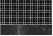
- FIG. 3 is a diagram showing an electron microscopic image of a main part of a well array including well 1 used in a preliminary test. It is a figure which shows the electron microscope image which imaged the example of preparation of a well array.
- Fig. 3 shows an example embodiment of a detection device;
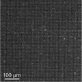
- FIG. 10 is a diagram showing a fluorescence image of a virus-containing specimen taken in an example.
- FIG. 10 is a diagram showing a fluorescence image of a virus-free specimen taken in an example.
- FIG. 4 shows an example of an embodiment of a well array according to the invention.
- FIG. 4 is an electron microscope image of an example of the preparation of the well array.
- the well array has a structure in which a plurality of wells are formed by partitioning the adjacent wells by sidewalls erected on the substrate.
- the material for forming the well array is not particularly limited and can be appropriately selected according to the purpose. Examples thereof include glass materials, semiconductor materials, resin materials, and the like.
- the method for forming the well array is not particularly limited and can be appropriately selected according to the purpose. well-known methods such as injection molding using a mold and imprinting to form the well array. For example, when forming the well array by lithography and reactive ion etching using silicon as a forming material, the processing limit is about 0.1 ⁇ m, and the well array can be formed with high definition.
- the upper surface of the side wall is subjected to a hydrophobic treatment from the viewpoint of facilitating the accommodation of the test liquid in the well.
- the method of the hydrophobization treatment is not particularly limited, and examples thereof include known methods such as coating treatment with a hydrophobic polymer (e.g., photoresist) and film formation treatment of a hydrophobic molecular layer (e.g., dimethyldichlorosilane). mentioned.
- a hydrophobic polymer e.g., photoresist
- a hydrophobic molecular layer e.g., dimethyldichlorosilane
- the well array is characterized by conditions of the wells formed by the above forming method.
- the conditions of the wells will be described below with reference to FIG. 2 again.
- the well array has a well formation area of 5 mm 2 or more, which is the area of the substrate in which wells 1 are formed in the test area.
- the well formation area refers to the area on the substrate where a plurality of wells 1 are formed as a group of wells 1 to be observed, and is different from the area for forming one well 1 .
- the reason why the well formation area is set to 5 mm 2 at the smallest is that the observation when the general-purpose observation device configured to have the 4 ⁇ objective lens and the full HD standard imaging element is used as the detection unit. This is because it is based on the field of view. That is, the larger the area that can be observed at once, the more wells that can be observed at once, resulting in higher virus detection sensitivity.
- observation field of view is less than 5 mm 2 , in order to perform high - sensitivity detection, multiple imaging is required and the detection process becomes complicated.
- the setting is based on the ability to observe the luminescence and non-luminescence states of each well 1 formed in the formation area.
- the detection unit may be configured by a wide-field observation device.
- the observation field of view can be set larger while maintaining the necessary visibility.
- a virus with higher sensitivity can be observed in one observation. Detection becomes possible.
- a 4K image sensor (3,840 x 2,160 pixels) or an 8K image sensor (7,680 x 4,320 pixels) is used, it will be possible to image a wider area with the same resolution, resulting in higher sensitivity. It becomes possible.
- the upper limit of the observation field of view is about 320 mm 2 from the imaging limit of a known imaging device.
- the upper limit of the well formation area can be said to be about 320 mm 2 , which is the same as the size of the observation field, from the viewpoint of performing high-sensitivity detection by utilizing the observation field without waste.
- it is more preferable to set the upper limit of the well formation area to about 100 mm 2 ( 1 cm ⁇ 1 cm).
- the total volume of the wells 1 obtained by integrating the volumes of the individual wells 1 in the test area is 17 nL or more.
- the reason why the total volume is at least 17 nL is that the general-purpose observation device is used to obtain detection sensitivity that realizes virus detection for the test fluid with a virus concentration of 100 aM (1 virus/17 nL) or less. With such detection sensitivity, the presence or absence of the virus can be detected from saliva as a screening test for virus-infected patients.
- the total volume can be set according to the target virus concentration, and the upper limit is about 4,000 nL from the upper limit of the well formation area and the limit of the depth D of the well 1 described later. is.
- a depth D of the well 1 is set to 3.5 ⁇ m to 40 ⁇ m. If the depth D is less than 3.5 ⁇ m, it is not possible to obtain the detection sensitivity required to detect viruses in the test fluid with a virus concentration of 100 aM (1 virus/17 nL) or less using the general-purpose observation device. Further, when the depth D exceeds 40 ⁇ m, the focus of the image pickup device cannot be adjusted in the entire depth direction. In addition, it becomes difficult for the test liquid to enter the entire well 1 . In addition, processing of the well 1 becomes difficult.
- the opening area A of the well 1 is set to 18 ⁇ m 2 to 1,700 ⁇ m 2 . If the opening area A is less than 18 ⁇ m 2 , the image of the well 1 will be too small to identify each well when using the general-purpose observation device. In addition, when the opening area A exceeds 1,700 ⁇ m 2 , the volume V of the well 1 reaches the detection limit when a substance that emits light without being involved in the virus is used as the light source. We cannot distinguish between the luminescence of 1 and the luminescence of well 1 where no virus is involved.
- the opening area A of the well 1 should be at least 18 ⁇ m 2 , but this setting is based on an estimate when imaging one well 1 with 3 pixels. In order to improve visibility, when imaging one well 1 with four pixels, the lower limit of the opening area A of the well 1 is set to 25 ⁇ m 2 .
- the shape of the opening is square, but the shape of the opening is not particularly limited. , may be elliptical. Further, the well 1 is not particularly limited as long as it has a columnar shape (square shape).
- the volume V of well 1 is between 74 fL and 6,000 fL. If the volume V is less than 74 fL, the general-purpose observation device cannot be used to obtain the detection sensitivity to detect the virus in the test fluid with a virus concentration of 100 aM or less. In addition, when the volume V exceeds 6,000 fL, the volume reaches the detection limit when a substance that emits light without being involved in the virus is used as the light source. It cannot be distinguished from the luminescence of well 1. By imaging one well 1 with 4 ⁇ 4 pixels or more, it is possible to obtain a clearer well image.
- the upper limit of the total number of wells 1 to be formed when using the general-purpose observation device is about 130,000 according to the number of pixels (480 ⁇ 270).
- the volume V of one well 1 should be at least 130 fL based on the relationship of 17 nL/130,000. Therefore, the lower limit of the volume V of the well 1 is more preferably 130 fL.
- a sidewall thickness T which is the thickness of the sidewall between adjacent wells 1, is set to 0.5 ⁇ m to 15 ⁇ m. If the side wall thickness T is less than 0.5 ⁇ m, processing becomes difficult and fragility occurs. Moreover, when the side wall thickness T exceeds 15 ⁇ m, the total volume tends to fall below the volume of the test liquid. When the spacing between adjacent wells 1 is not uniform, such as when the wells 1 are formed in a circular or elliptical shape, the side wall thickness T is the thinnest portion of the spacing between the adjacent wells 1. Determined by thickness.
- the general-purpose observation device can be used to detect the virus in the test solution having a virus concentration of 100 aM or less. Sensitivity of detection to achieve detection can be obtained. In addition, it can be used for virus detection by the virus direct capture method without using the magnetic beads, and the virus can be detected in a short time. In addition, one minute detection of viruses can also be achieved under suitable conditions.
- ⁇ Test area> As the well array, in addition to the wells in which the test solution is stored and the luminescence detection is performed, arbitrary wells which are not subject to luminescence detection, i.e., which are located outside the observation field of the detection unit, may be formed. good.
- the area of the observation field of view in the detection unit in which the observation field of view is fixed and the area of the formation region of the well in which the test liquid is accommodated and luminescence is detected may be of the same size.
- the well array is provided with a "waste margin" outside the observation field of view.
- a region may be provided and the arbitrary well may be formed in this region. That is, when the arbitrary well does not exist, it may take a long time to align the field of view with the formation region of the well because the size of the well is very small. If an arbitrary well exists, alignment can be easily performed using the visibility of the outline recognized in the outermost arbitrary well. That is, when the arbitrary well exists, the observation field of view and the formation region of the well can be aligned simply by determining the contour and setting the observation field of view inside it.
- the arbitrary well may be formed to have the same size as the well in which the test liquid is stored and the luminescence is detected. It may be formed in a size different from that of the well for detection.
- the well formation region to be observed is referred to as the "test region” to distinguish it from the "waste allowance” region that is not to be observed.
- the terms “well forming area”, “total well volume”, “well depth”, “well opening area”, “well volume” and “side wall thickness” are Note that it means “well forming area”, “total well volume”, “well depth”, “well open area”, “well volume” and “sidewall thickness” in the detection area. .
- the detection device of the present invention has a detection chip and a detection unit on which the well array of the present invention is arranged.
- An example of embodiment of the detection device is shown in FIG.
- the detection device 10 has a detection chip 2 in which a well array 1' having a plurality of wells 1 described above is arranged, and a detection unit 3. As shown in FIG.
- the detection chip 2 is not particularly limited except that the well 1 and the well array 1′ having the characteristics described above are arranged, and can be manufactured according to a known configuration. It can be manufactured according to the configuration of the detection chip 100 (see FIGS. 1A and 1B) in which a space 130 is formed between the chip 120 and the chip 120 .
- the upper portion of the well array 1′ is sealed with a transparent resin or silicone rubber, or a hydrophobic solvent is dropped onto the well array 1′ to block the upper portion of the well 1 and a cover glass is placed thereon. It is also possible to have a configuration in which it is placed.
- the detection unit 3 can fix the observation field of view to a size that includes the test area in the well array 1'.
- the detection unit 3 is configured according to the configuration of a detection unit employed in a known microscope. Configured. Further, instead of the general-purpose observation device, the wide-field observation device may be configured with the double objective lens, a 4K image sensor, an 8K image sensor, or the like.
- the observation field of the detection unit 3 may have a size that includes the subject area, but preferably has a size equivalent to the subject area. When the observation field of view and the test area are set to have the same size in this way, the observation field of view can be used without waste to perform high-sensitivity detection.
- the detection device When fluorescence is detected as the light emitted from the well 1, the detection device includes a light irradiation unit for irradiating light for exciting fluorescence.
- This light irradiating section is configured according to the configuration of a known light irradiating section for fluorescence excitation, and is configured, for example, by a light source for fluorescence excitation selected according to the excitation wavelength of a substance that causes fluorescence emission in the well 1. be done.
- a light source for fluorescence excitation selected according to the excitation wavelength of a substance that causes fluorescence emission in the well 1. be done.
- known light sources such as lasers, LEDs, and lamps can be used, and lenses and optical filters may be combined as necessary.
- the test solution having a virus concentration of 100 aM (1 virus/17 nL) or less can be detected using the general-purpose observation device. detection sensitivity to achieve virus detection against In addition, it can be used for virus detection by the virus direct capture method without using the magnetic beads, and the virus can be detected in a short time. In addition, one minute detection of viruses can also be achieved under suitable conditions.
- the virus detection method of the present invention is a method of detecting a virus in the test solution based on luminescence detection of the wells using the well array of the present invention. It is carried out in a detection unit in which the observation field of view is fixed in size.
- the observation field of the detection unit may have a size that includes the inspection area, but preferably has a size equivalent to the inspection area. When the observation field of view and the test area are set to have the same size, the observation field of view can be used without waste to perform high-sensitivity detection.
- viruses to be detected are not particularly limited, and include viruses that can be detected by known virus detection methods such as ELISA and immunoassay methods. Examples include influenza virus, norovirus, and coronavirus.
- the method for detecting luminescence in the wells is not particularly limited, and may include an adsorption reaction that emits light when the virus is present, or a luminescence detection method that uses an enzymatic reaction or a chemical reaction. a method of causing the well to emit light by causing the well to emit light, a method of causing the well to emit light using a reagent that produces a fluorescent substance through an enzymatic reaction with a virus protein, a reagent that produces a chemiluminescent substance through an enzymatic reaction with a virus protein and a method of causing the well to emit light.
- the luminescent substance is not particularly limited and can be appropriately selected according to the type of virus, etc.
- an aggregation-induced luminescent (AIE) substance is preferable.
- the aggregation-inducing luminescent substance include compounds that produce the AIE effect described in JP-A-2010-112777.
- the reagent for generating a fluorescent substance through an enzymatic reaction with a protein in the virus is not particularly limited and can be appropriately selected according to the type of virus.
- Fluorescein a derivative containing 4-methylumbelliferone, such as (4-methylumbelliferyl)- ⁇ -DN-acetylneuraminic acid, which produces the substance 4-methylumbelliferone
- Derivatives containing, derivatives containing Resorufin, derivatives containing Rhodamine, and the like can be mentioned.
- the reagent that generates a chemiluminescent substance through an enzymatic reaction with the protein in the virus is not particularly limited and can be appropriately selected according to the type of virus, and examples thereof include known artificial luciferin. .
- the luminescence detection of the well is carried out by detecting the luminescence of the well with the detection unit after the test solution containing the virus and a substance (reagent) that causes the well to emit light is contained in the well.
- the method of accommodating the test liquid in the well is not particularly limited. ), the test liquid is prepared as a hydrophilic solvent and introduced into the space 130, and then a hydrophobic solvent is introduced into the space 130 to introduce the test liquid into the well.
- a method of accommodating the test liquid in the well by enclosing the .
- a transparent resin or silicone rubber is pressed onto the well array for sealing, and the test liquid is placed in the well.
- the hydrophilic solvent on the surface is replaced with a hydrophobic solvent, and a cover glass is placed on it.
- a method of accommodating the test liquid in the well is exemplified.
- the virus concentration of 100 aM (1/17 nL) or less can be detected using the general-purpose observation device. Sensitivity of detection can be obtained to achieve virus detection for fluids. In addition, it can be used for virus detection by the virus direct capture method without using the magnetic beads, and the virus can be detected in a short time. In addition, one minute detection of viruses can also be achieved under suitable conditions.
- the following detection test was performed using the influenza virus as the detection target.
- the well array had a square opening shape of 7 ⁇ m on each side, an opening area of 49 ⁇ m 2 with a depth D of 10 ⁇ m, a volume of 490 fL, and a side wall thickness T of 3 ⁇ m.
- a number of 50,451 formed on a silicon substrate was used.
- This well array had a well formation area of 5 mm 2 and a total volume of 25 nL, and was produced by a known shape processing method using photolithography and dry etching.
- a detection reagent in which a peptide molecule that binds to the influenza virus is bound to tetraphenylsilole which is an aggregation-inducing luminescent substance (H Shi et al., Journal of the American Chemical Society 134 , pp. 9569 (2012)).
- a camera for observing the well array a CMOS camera of 2,048 ⁇ 2,048 pixels (4,194,304 pixels) (manufactured by Hamamatsu Photonics, ORCA-Flash 4.0 ⁇ 3) was used.
- the observation field range when observed with a 4 ⁇ objective lens is 3.25 mm ⁇ 3.25 mm, and the entire well array can be observed.
- the detection method As for the details of the detection method, first, 30 ⁇ L of the sample solution containing the influenza virus and 30 ⁇ L of an aggregation-inducing luminescent substance solution having a concentration of 0.4 ⁇ M were added and mixed, and 50 ⁇ L of the mixture was aliquoted and introduced into the well array. Then, the well array was sealed with fluorine oil, covered with a cover glass, and observed with a fluorescence microscope (Olympus, BXFM) using the 4x objective lens. The binding of the influenza virus and the aggregation-inducing luminescent substance causes fluorescence enhancement of the aggregation-inducing luminescent substance. Indeed, the wells encapsulating the influenza virus appeared brighter than the wells without the influenza virus.
- the brightness of each of the wells is the average value of the brightness values in a range of 200 x 200 pixels in the portion where the well array is not formed located outside the well array.
- a value obtained by normalizing the value (normalized luminance value) was used for analysis.
- the threshold value for determining the luminescence well was defined as ⁇ +3.3 ⁇ using the average ⁇ and the standard deviation ⁇ of the normalized luminance values measured in the samples containing no influenza virus. The wells exceeding the threshold value were counted as the luminescent wells, and the value was used as the measured value corresponding to the influenza virus concentration.
- FIG. 6 shows an example of a fluorescence image taken with a sample containing influenza virus at a final concentration of 1 ⁇ 10 5 copies/mL
- FIG. 7 shows an example of a fluorescence image taken with the blank sample.
- a comparison of FIG. 6 and FIG. 7 reveals that in the sample containing the influenza virus, wells that are brighter (whiter) than the surrounding wells are observed, whereas in the sample that does not contain the influenza virus, most of the wells are comparable. Brightness can be confirmed.
- the number of luminescence wells counted for the entire well array was 61 for the sample containing the influenza virus, and 8 for the sample not containing the influenza virus. , and the detection of the influenza virus can be realized.
- the sample has at least 20 luminescent wells, it is possible to significantly distinguish it from the sample that does not contain the influenza virus. , allowing virus detection down to samples containing said influenza virus at a final concentration of approximately 3 ⁇ 10 4 copies/mL. Said final concentration (3 ⁇ 10 4 copies/mL) is the concentration corresponding to 50 aM.
- the binding reaction between the influenza virus and the aggregation-inducing luminescent substance is completed within 10 seconds. can be completed within 1 minute. That is, the present invention realizes virus detection with high speed and high sensitivity.
- detection chip 1 well 1' well array 2 detection chip 3 detection unit 10 detection device L light emission 100 detection chip 110 lower layer 111 side wall 115a-115b well 120 upper layer 121 inlet 130 space 140 hydrophilic solvent 150 hydrophobic solvent 161 virus 162 fluorescence coloration sexual substrate 163 reaction product
Landscapes
- Health & Medical Sciences (AREA)
- Life Sciences & Earth Sciences (AREA)
- Chemical & Material Sciences (AREA)
- Immunology (AREA)
- Engineering & Computer Science (AREA)
- Molecular Biology (AREA)
- Hematology (AREA)
- Urology & Nephrology (AREA)
- Biomedical Technology (AREA)
- General Health & Medical Sciences (AREA)
- Analytical Chemistry (AREA)
- Biochemistry (AREA)
- Physics & Mathematics (AREA)
- Microbiology (AREA)
- Biotechnology (AREA)
- General Physics & Mathematics (AREA)
- Pathology (AREA)
- Food Science & Technology (AREA)
- Cell Biology (AREA)
- Medicinal Chemistry (AREA)
- Virology (AREA)
- Organic Chemistry (AREA)
- Tropical Medicine & Parasitology (AREA)
- Zoology (AREA)
- Proteomics, Peptides & Aminoacids (AREA)
- Wood Science & Technology (AREA)
- Toxicology (AREA)
- Biophysics (AREA)
- Chemical Kinetics & Catalysis (AREA)
- Clinical Laboratory Science (AREA)
- Bioinformatics & Cheminformatics (AREA)
- General Engineering & Computer Science (AREA)
- Genetics & Genomics (AREA)
- Nuclear Medicine, Radiotherapy & Molecular Imaging (AREA)
- Measuring Or Testing Involving Enzymes Or Micro-Organisms (AREA)
Priority Applications (3)
| Application Number | Priority Date | Filing Date | Title |
|---|---|---|---|
| JP2023508905A JP7734442B2 (ja) | 2021-03-26 | 2022-03-04 | ウエルアレイを用いたウイルス検出方法、ウエルアレイ及び検出装置 |
| US18/552,365 US20240168023A1 (en) | 2021-03-26 | 2022-03-04 | Virus detection method using well array, well array, and detection device |
| EP22775013.0A EP4290221A4 (en) | 2021-03-26 | 2022-03-04 | VIRUS DETECTION METHOD USING TRACK NETWORK, TRACK NETWORK AND DETECTION DEVICE |
Applications Claiming Priority (2)
| Application Number | Priority Date | Filing Date | Title |
|---|---|---|---|
| JP2021-053010 | 2021-03-26 | ||
| JP2021053010 | 2021-03-26 |
Publications (1)
| Publication Number | Publication Date |
|---|---|
| WO2022202217A1 true WO2022202217A1 (ja) | 2022-09-29 |
Family
ID=83396959
Family Applications (1)
| Application Number | Title | Priority Date | Filing Date |
|---|---|---|---|
| PCT/JP2022/009368 Ceased WO2022202217A1 (ja) | 2021-03-26 | 2022-03-04 | ウエルアレイを用いたウイルス検出方法、ウエルアレイ及び検出装置 |
Country Status (4)
| Country | Link |
|---|---|
| US (1) | US20240168023A1 (https=) |
| EP (1) | EP4290221A4 (https=) |
| JP (1) | JP7734442B2 (https=) |
| WO (1) | WO2022202217A1 (https=) |
Cited By (1)
| Publication number | Priority date | Publication date | Assignee | Title |
|---|---|---|---|---|
| CN117264749A (zh) * | 2023-11-23 | 2023-12-22 | 中国科学院空天信息创新研究院 | 多指标检测装置及其使用方法 |
Citations (9)
| Publication number | Priority date | Publication date | Assignee | Title |
|---|---|---|---|---|
| JP3886161B2 (ja) | 1997-03-14 | 2007-02-28 | トラスティーズ・オブ・タフツ・カレッジ | コード化微小球による光ファイバーセンサー |
| JP2010112777A (ja) | 2008-11-05 | 2010-05-20 | Saitama Univ | ウィルス、微生物類の検出方法 |
| WO2012121310A1 (ja) | 2011-03-08 | 2012-09-13 | 独立行政法人科学技術振興機構 | ビーズ封入方法、ターゲット分子を検出する方法、アレイ、キット及びターゲット分子検出装置 |
| JP5363663B2 (ja) | 2010-03-01 | 2013-12-11 | クワンテリクス コーポレーション | 分子または粒子を検出するアッセイにおけるダイナミックレンジを拡張するための方法またはシステム |
| JP5551798B2 (ja) | 2010-03-01 | 2014-07-16 | クワンテリクス コーポレーション | ビーズまたは他の捕捉物を用いた分子または粒子の超高感度検出 |
| WO2016006208A1 (ja) | 2014-07-08 | 2016-01-14 | 国立研究開発法人科学技術振興機構 | 物質封入方法及びターゲット分子を検出する方法 |
| JP2018038384A (ja) | 2016-09-05 | 2018-03-15 | 国立研究開発法人科学技術振興機構 | 病原性微生物検出のための方法及びキット |
| JP2018091737A (ja) | 2016-12-05 | 2018-06-14 | 国立大学法人 東京大学 | 蛍光観察装置 |
| WO2018181488A1 (ja) * | 2017-03-29 | 2018-10-04 | 国立研究開発法人科学技術振興機構 | 微小物質検出方法及び微小物質検出用デバイス |
Family Cites Families (1)
| Publication number | Priority date | Publication date | Assignee | Title |
|---|---|---|---|---|
| US10324041B2 (en) * | 2016-12-21 | 2019-06-18 | Abbott Japan Co., Ltd. | Optical imaging system using lateral illumination for digital assays |
-
2022
- 2022-03-04 JP JP2023508905A patent/JP7734442B2/ja active Active
- 2022-03-04 WO PCT/JP2022/009368 patent/WO2022202217A1/ja not_active Ceased
- 2022-03-04 EP EP22775013.0A patent/EP4290221A4/en not_active Withdrawn
- 2022-03-04 US US18/552,365 patent/US20240168023A1/en active Pending
Patent Citations (9)
| Publication number | Priority date | Publication date | Assignee | Title |
|---|---|---|---|---|
| JP3886161B2 (ja) | 1997-03-14 | 2007-02-28 | トラスティーズ・オブ・タフツ・カレッジ | コード化微小球による光ファイバーセンサー |
| JP2010112777A (ja) | 2008-11-05 | 2010-05-20 | Saitama Univ | ウィルス、微生物類の検出方法 |
| JP5363663B2 (ja) | 2010-03-01 | 2013-12-11 | クワンテリクス コーポレーション | 分子または粒子を検出するアッセイにおけるダイナミックレンジを拡張するための方法またはシステム |
| JP5551798B2 (ja) | 2010-03-01 | 2014-07-16 | クワンテリクス コーポレーション | ビーズまたは他の捕捉物を用いた分子または粒子の超高感度検出 |
| WO2012121310A1 (ja) | 2011-03-08 | 2012-09-13 | 独立行政法人科学技術振興機構 | ビーズ封入方法、ターゲット分子を検出する方法、アレイ、キット及びターゲット分子検出装置 |
| WO2016006208A1 (ja) | 2014-07-08 | 2016-01-14 | 国立研究開発法人科学技術振興機構 | 物質封入方法及びターゲット分子を検出する方法 |
| JP2018038384A (ja) | 2016-09-05 | 2018-03-15 | 国立研究開発法人科学技術振興機構 | 病原性微生物検出のための方法及びキット |
| JP2018091737A (ja) | 2016-12-05 | 2018-06-14 | 国立大学法人 東京大学 | 蛍光観察装置 |
| WO2018181488A1 (ja) * | 2017-03-29 | 2018-10-04 | 国立研究開発法人科学技術振興機構 | 微小物質検出方法及び微小物質検出用デバイス |
Non-Patent Citations (13)
| Title |
|---|
| DAVID M RISSIN ET AL., ANALYTICAL CHEMISTRY, vol. 83, 2011, pages 2279 |
| DAVID M RISSIN ET AL., NATURE BIOTECHNOLOGY, vol. 28, no. 6, 2010, pages 595 |
| ELENA PEREZ-RUIZ ET AL., ANALYTICA CHIMICA ACTA, vol. 1015, 2018, pages 74 |
| ENZYME-LINKED IMMUNO SORBENT ASSAY |
| H SHI ET AL., JOURNAL OF THE AMERICAN CHEMICAL SOCIETY, vol. 134, 2012, pages 9569 |
| KAZUHITO V. TABATA ET AL., SCIENTIFIC REPORTS, vol. 9, 2019, pages 1067 |
| KAZUHITO V. TABATA, YOSHIHIRO MINAGAWA, YUKO KAWAGUCHI, MANA ONO, YOSHIKI MORIIZUMI, SEIYA YAMAYOSHI, YOICHIRO FUJIOKA, YUSUKE OHB: "Antibody-free digital influenza virus counting based on neuraminidase activity", SCIENTIFIC REPORTS, vol. 9, no. 1, 1 December 2019 (2019-12-01), XP055676628, DOI: 10.1038/s41598-018-37994-6 * |
| LEIRS KAREN, TEWARI KUMAR PHALGUNI, DECROP DEBORAH, PÉREZ-RUIZ ELENA, LEBLEBICI PELIN, VAN KELST BRAM, COMPERNOLLE GRIET, MEEUWS H: "Bioassay Development for Ultrasensitive Detection of Influenza A Nucleoprotein Using Digital ELISA", ANALYTICAL CHEMISTRY, AMERICAN CHEMICAL SOCIETY, US, vol. 88, no. 17, 6 September 2016 (2016-09-06), US , pages 8450 - 8458, XP055969682, ISSN: 0003-2700, DOI: 10.1021/acs.analchem.6b00502 * |
| MINAGAWA YOSHIHIRO, UENO HIROSHI, TABATA KAZUHITO V., NOJI HIROYUKI: "Mobile imaging platform for digital influenza virus counting", LAB ON A CHIP, ROYAL SOCIETY OF CHEMISTRY, UK, vol. 19, no. 16, 6 August 2019 (2019-08-06), UK , pages 2678 - 2687, XP055969681, ISSN: 1473-0197, DOI: 10.1039/C9LC00370C * |
| See also references of EP4290221A4 |
| SOO HYEON KIM ET AL., LAB ON A CHIP, vol. 12, 2012, pages 4986 |
| STEPHANIE M. SCHUBERT ET AL., ANALYTICAL CHEMISTRY, vol. 88, 2016, pages 8450 |
| YOSHIHIRO MINAGAWA ET AL., LAB ON A CHIP, vol. 19, 2019, pages 2678 |
Cited By (2)
| Publication number | Priority date | Publication date | Assignee | Title |
|---|---|---|---|---|
| CN117264749A (zh) * | 2023-11-23 | 2023-12-22 | 中国科学院空天信息创新研究院 | 多指标检测装置及其使用方法 |
| CN117264749B (zh) * | 2023-11-23 | 2024-02-02 | 中国科学院空天信息创新研究院 | 多指标检测装置及其使用方法 |
Also Published As
| Publication number | Publication date |
|---|---|
| EP4290221A1 (en) | 2023-12-13 |
| EP4290221A4 (en) | 2025-02-26 |
| JP7734442B2 (ja) | 2025-09-05 |
| US20240168023A1 (en) | 2024-05-23 |
| JPWO2022202217A1 (https=) | 2022-09-29 |
Similar Documents
| Publication | Publication Date | Title |
|---|---|---|
| George et al. | Sensitive detection of protein and miRNA cancer biomarkers using silicon-based photonic crystals and a resonance coupling laser scanning platform | |
| JP2024502618A5 (https=) | ||
| JP5934921B2 (ja) | 診断キット及びその使用方法 | |
| JP5910977B2 (ja) | 検出装置及び検出方法 | |
| CN108474743B (zh) | 流体中的物质的光学探测 | |
| US20200033193A1 (en) | Spectral microscope | |
| KR100500610B1 (ko) | 형광 현미경 및 이를 사용한 관측 방법 | |
| CN116438438A (zh) | 用于基于流动的单颗粒和/或单分子分析的方法和设备 | |
| JP2017508993A (ja) | 生物学的検体を分析するための方法およびデバイス | |
| US20220137037A1 (en) | Device and method for detecting protein-based marker, and method for manufacturing chip | |
| WO2020235607A1 (ja) | 標的分子の検出方法 | |
| US20160061730A1 (en) | Fluorescence detection apparatus, test substance detection apparatus, and fluorescence detection method | |
| KR102846841B1 (ko) | 형광분광기술을 이용한 진단분석장치 | |
| Ashiba et al. | Quick and ultra-sensitive digital assay of influenza virus using sub-picoliter microwells | |
| WO2022202217A1 (ja) | ウエルアレイを用いたウイルス検出方法、ウエルアレイ及び検出装置 | |
| JP2016512597A (ja) | 検定の検出感度を向上させる方法とシステム | |
| JP2009092405A (ja) | 標的物質検出用素子、それを用いた標的物質検出装置、キット及び検出方法 | |
| CN104614367B (zh) | 一种多通道光学检测系统 | |
| CN114729889A (zh) | 荧光检测用生物分子检查芯片 | |
| WO2018100780A1 (ja) | 標的物質検出装置及び標的物質検出方法 | |
| WO2019131592A1 (ja) | 標的分子の検出における偽陰性判定の発生を抑制する方法および検出デバイス | |
| EP3189325A1 (en) | Method and apparatus for optical measurement of liquid sample | |
| US20250189520A1 (en) | A method for detecting an analyte | |
| US12203851B2 (en) | Method for detecting objective substance | |
| US20230314419A1 (en) | Target measurement method, target measurement device, target measurement apparatus, and target measurement kit |
Legal Events
| Date | Code | Title | Description |
|---|---|---|---|
| 121 | Ep: the epo has been informed by wipo that ep was designated in this application |
Ref document number: 22775013 Country of ref document: EP Kind code of ref document: A1 |
|
| ENP | Entry into the national phase |
Ref document number: 2023508905 Country of ref document: JP Kind code of ref document: A |
|
| WWE | Wipo information: entry into national phase |
Ref document number: 2022775013 Country of ref document: EP |
|
| ENP | Entry into the national phase |
Ref document number: 2022775013 Country of ref document: EP Effective date: 20230905 |
|
| WWE | Wipo information: entry into national phase |
Ref document number: 18552365 Country of ref document: US |
|
| NENP | Non-entry into the national phase |
Ref country code: DE |
|
| WWW | Wipo information: withdrawn in national office |
Ref document number: 2022775013 Country of ref document: EP |